Pre-Feasibility Report For Proposed Expansion of Petrochemicals and Synthetic Organic Manufacturing Capacity at MIDC TALOJA 5 (e) and 5 (f) category Prepared By M/s IG Petrochemicals Limited T-2, M.I.D.C Taloja, Dist : Raigad – 410208, Maharashtra, India Tel.: 022 - 39289102 Web site: www.igpetro.com
Transcript
Pre-Feasibility Report
For
Proposed Expansion of Petrochemicals and Synthetic Organic Manufacturing Capacity
at
MIDC TALOJA
5 (e) and 5 (f) category
Prepared By
M/s IG Petrochemicals Limited T-2, M.I.D.C Taloja,
Table 3-19 The Proposed Additional Fuel Requirement for Coal Fired Boiler and proposed FO fired
boiler is as follows ..................................................................................................................................... 32
Table 3-20 from proposed PA 4 (nonhazardous) ........................................................................................ 33
Table 3-21 from proposed PA 4 (Hazardous) ............................................................................................ 33
Table 3-22 from proposed Plasticizer (Non Hazardous Waste) ................................................................. 34
Table 3-23 from proposed Plasticizer (hazardous waste) ........................................................................... 34
List of Figures
Figure 2.1 PA usage pattern ......................................................................................................................... 8
Figure 3.1 Block Diagram of DOP/DIOP/DIDP/DBP/DIBP Manufacturing .................................................. 19
Figure 4.1 Wind Rose Winter 2014 (Jan-Feb 2014) .................................................................................... 36
List of Annexures
Sr No Description Page no
I IG Petrochemicals Google image 46
II Proposed layout plan 47
III Proposed ETP Block diagram 48
Prefeasibility Report for Proposed Expansion IG Petrochemicals Limited, Taloja
1
EXECUTIVE SUMMARY 1
I G Petrochemicals Ltd. (IGPL) is an established market leader in Phthalic Anhydride (PAN) with strong recognition and excellent plant facilities of international standards. Phthalic Anhydride (PAN) is used in industries such as flexible PVC, plastics, paints, construction, transportation and marine. IGPL commenced production in the year 1992 with a view to become one of the leading
players in the petrochemicals industry. Today, we are the largest producer of PAN in India. Our dynamic spirit to go beyond the normal realms of success and our relentless will to be the market leader has been the hallmarks of our pursuit of excellence. IGPL is promoted by the Dhanuka Group in technical collaboration with Lurgi GmbH, Germany. The plant is located at MIDC, Taloja in Raigad District, Maharashtra, India, 50 Km from Jawaharlal Nehru Port Trust (JNPT), Maharashtra, thus enabling us to provide unsurpassed customer service to versatile and diversified market since 1992.
Phthalic Anhydride (PAN) is used in manufacturing plasticizers, which are most essential in making PVC products, shoe soles, cables, pipes and hoses, leather cloth, films for packaging and other products. It is also used to manufacture alkyd resins used in paints and in the production of unsaturated polyester resins for building materials, plastic products, textile industries and printing inks Being a "value driven" company, the values are a part of individual and collective objectives for continuous business excellence. Equipped with one of the largest capacity at a single location, the Company has the ability to cater to local and international market.
Our evolution of growth is captured in the following table
Table 1-1 Growth milestones
Year Description
1988 Incorporated as 100% EOU in technical collaboration with Lurgi GmbH, Germany.
1992 – 1993 Started production with initial capacity of 45,000 MTPA (PA 1)
1997 – 1998 Brownfield expansion of 50,000 MTPA (PA 2)
2006 – 2007 Debottlenecking of capacity by 26100 MTPA
2008 – 2009 Converted from EOU to DTA
2013 – 2014 Brownfield expansion of 53,000 MTPA (PA 3) with recovery of
Prefeasibility Report for Proposed Expansion IG Petrochemicals Limited, Taloja
2
Year Description
Benzoic acid 1000 TPA from residue/effluent & 2.5 MW Captive Power to grid Total PA Licensed Capacity of 169,110 MTPA
In order to capture international growing market of Phthalic anhydride and its value added downstream products, Company proposes to expand its manufacturing base at site as follows: Proposed additional production capacities are:
Table 1-2 Proposed production quantities
S. N. Name of Product Quantity (MTPA)
1 PA Manufacturing Division
a Phthalic Anhydride (PA) 53,000
b By product Benzoic Acid (recovery from effluent & residue)
500
2 Plasticizers Manufacturing Division
a Di- Octyl Phthalate (DOP)
62,500
b Di-Iso Octyl Phthalate (DIOP)
c Di-Iso Nonyl Phthalate (DINP)
d Di- Decyl Phthalate (DIDP)
e Di- Butyl Phthalate (DBP)
f Di- Iso Butyl Phthalate (DIBP)
g Di Methyl phthalate (DMP)
h Di Ethyl phthalate (DEP)
By products
i Sodium sulphate 900
j Phthalic Acid 800
The expansion is proposed to be at existing plot no T-2, V-45, V-11 to V 14, T-2/1 and
adjacent acquired plot No T– 2 (part) which is at Taloja MIDC area, Dist Raigad, Maharashtra. The total land on Plot is 118,026 sq m (Existing T-2, V-45, V-11 to V 14, T-2/1 plots are 100,876 sq m and acquired T– 2 (part) is 17150 Sq. m). Since majority of existing plant/land area (>80%) is in plot T-2, the applications are generally made showing plot T-2. The Google image of the existing and proposed area is at Annexure – I Existing/Proposed Layout Plan for expansion is attached as Annexure–II.
Prefeasibility Report for Proposed Expansion IG Petrochemicals Limited, Taloja
3
The Land is already in use as “Industrial” (all plots are in MIDC Chemical zone) thus there is no change in land use. MIDC has provided basic infrastructure like Electrical Power, water supply, the internal road network, external approach road (connecting site to NH4 and Mumbai-Pune Expressway), CHWSTDF (Common Hazardous Waste Storage Treatment and Disposal Facility), and underground effluent line connected to CETP. There is no sensitive establishment in the vicinity such as health resort, hospital, archaeological monuments, Wild Life sanctuaries, National Parks etc.
To treat both effluents Industrial & Domestic, the combined Effluent Treatment Plant (ETP) provided shall be suitably enhanced to treat entire effluent quantity. This unit is registered under Factories Act. All the significant risks identified are controlled through Engineering/Operational/PPE controls. Trained First Aid and Fire Fighting team are available in every shift. Also qualified Safety Officer is employed by the company. Company is accredited ISO 9001: 2008 and ISO 14001: 2004. Firefighting system is installed as per MIDC guidelines. The industry will manufacture additional products as mentioned in chapter 2 below. This
will not disturb the present land use. Sufficient greenbelt is developed & maintained as required.
Prefeasibility Report for Proposed Expansion IG Petrochemicals Limited
INTRODUCTION OF THE PROJECT / 2BACKGROUND INFORMATION
Identification of the project and Project Proponent 2.1
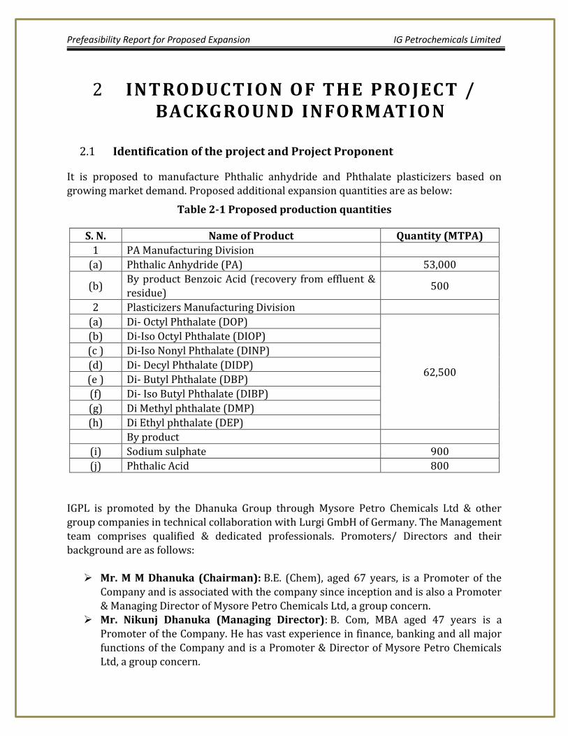
It is proposed to manufacture Phthalic anhydride and Phthalate plasticizers based on growing market demand. Proposed additional expansion quantities are as below:
Table 2-1 Proposed production quantities
S. N. Name of Product Quantity (MTPA)
1 PA Manufacturing Division
(a) Phthalic Anhydride (PA) 53,000
(b) By product Benzoic Acid (recovery from effluent & residue)
500
2 Plasticizers Manufacturing Division
(a) Di- Octyl Phthalate (DOP)
62,500
(b) Di-Iso Octyl Phthalate (DIOP)
(c ) Di-Iso Nonyl Phthalate (DINP)
(d) Di- Decyl Phthalate (DIDP)
(e ) Di- Butyl Phthalate (DBP)
(f) Di- Iso Butyl Phthalate (DIBP)
(g) Di Methyl phthalate (DMP)
(h) Di Ethyl phthalate (DEP)
By product
(i) Sodium sulphate 900
(j) Phthalic Acid 800
IGPL is promoted by the Dhanuka Group through Mysore Petro Chemicals Ltd & other group companies in technical collaboration with Lurgi GmbH of Germany. The Management team comprises qualified & dedicated professionals. Promoters/ Directors and their background are as follows: Mr. M M Dhanuka (Chairman): B.E. (Chem), aged 67 years, is a Promoter of the
Company and is associated with the company since inception and is also a Promoter & Managing Director of Mysore Petro Chemicals Ltd, a group concern.
Mr. Nikunj Dhanuka (Managing Director): B. Com, MBA aged 47 years is a Promoter of the Company. He has vast experience in finance, banking and all major
functions of the Company and is a Promoter & Director of Mysore Petro Chemicals Ltd, a group concern.
Prefeasibility Report for Proposed Expansion IG Petrochemicals Limited
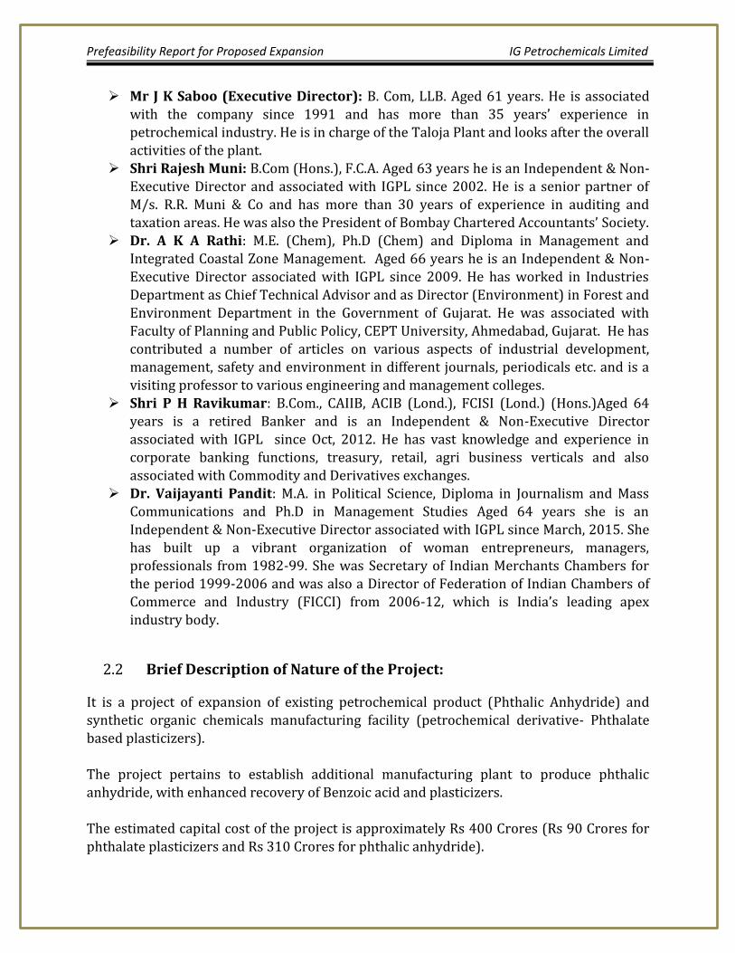
Mr J K Saboo (Executive Director): B. Com, LLB. Aged 61 years. He is associated with the company since 1991 and has more than 35 years’ experience in petrochemical industry. He is in charge of the Taloja Plant and looks after the overall activities of the plant.
Shri Rajesh Muni: B.Com (Hons.), F.C.A. Aged 63 years he is an Independent & Non-Executive Director and associated with IGPL since 2002. He is a senior partner of M/s. R.R. Muni & Co and has more than 30 years of experience in auditing and taxation areas. He was also the President of Bombay Chartered Accountants’ Society.
Dr. A K A Rathi: M.E. (Chem), Ph.D (Chem) and Diploma in Management and Integrated Coastal Zone Management. Aged 66 years he is an Independent & Non-
Executive Director associated with IGPL since 2009. He has worked in Industries Department as Chief Technical Advisor and as Director (Environment) in Forest and Environment Department in the Government of Gujarat. He was associated with Faculty of Planning and Public Policy, CEPT University, Ahmedabad, Gujarat. He has contributed a number of articles on various aspects of industrial development, management, safety and environment in different journals, periodicals etc. and is a visiting professor to various engineering and management colleges.
Shri P H Ravikumar: B.Com., CAIIB, ACIB (Lond.), FCISI (Lond.) (Hons.)Aged 64 years is a retired Banker and is an Independent & Non-Executive Director associated with IGPL since Oct, 2012. He has vast knowledge and experience in corporate banking functions, treasury, retail, agri business verticals and also
associated with Commodity and Derivatives exchanges. Dr. Vaijayanti Pandit: M.A. in Political Science, Diploma in Journalism and Mass
Communications and Ph.D in Management Studies Aged 64 years she is an Independent & Non-Executive Director associated with IGPL since March, 2015. She has built up a vibrant organization of woman entrepreneurs, managers, professionals from 1982-99. She was Secretary of Indian Merchants Chambers for the period 1999-2006 and was also a Director of Federation of Indian Chambers of Commerce and Industry (FICCI) from 2006-12, which is India’s leading apex industry body.
Brief Description of Nature of the Project: 2.2
It is a project of expansion of existing petrochemical product (Phthalic Anhydride) and synthetic organic chemicals manufacturing facility (petrochemical derivative- Phthalate based plasticizers). The project pertains to establish additional manufacturing plant to produce phthalic anhydride, with enhanced recovery of Benzoic acid and plasticizers. The estimated capital cost of the project is approximately Rs 400 Crores (Rs 90 Crores for
phthalate plasticizers and Rs 310 Crores for phthalic anhydride).
Prefeasibility Report for Proposed Expansion IG Petrochemicals Limited
Need of project with description for region and country 2.3
Phthalic anhydride 2.3.1
The Indian market is consuming approximately 27,000 Mt per month of Phthalic anhydride and growing at a rate of about 6-7% per annum.
There is an import of Phthalic anhydride of almost 6,000 MT per month which can
be substituted by the local Manufacturers like IG Petrochemicals Ltd and M/s.
Thirumalai Chemicals Ltd. More so with the fact that there is anti-dumping duty imposed on most countries against imports into India.
Thus there is a huge opportunity going forward to increase the capacitates in India
thereby reducing the cost of production which in turn will make us more competitive not only in India but in the global markets too.
Region wise PA production capacities are as follows:
Table 2-2 Region wise PA production capacities
Region India Europe China Rest Asia Pacific Others
Production (KTA)
290 800 2500 890 1200
Phthalate Plasticizer 2.3.2
1. Plasticizers have long been known for their effectiveness in producing flexible plastics for applications ranging from the automotive industry to medical and consumer products. The plasticizer industry has grown with the use of plastics worldwide.
2. Plastic industry has been identified as a major foreign exchange earner (As per policy Resolution for Petrochemicals published, 26th April, 2007). As the plastic industry continues to grow, so does the plasticizer industry.
3. The global plasticizers market is driven by factors such as emerging global economy and changing lifestyles.
In 2011 regional demand for Plasticizers was as in below.
Region North
America
Latin
America
Europe Rest of
world
Asia
Pacific
Consumption 0.8 0.3 1.0 0.8 3.5
Prefeasibility Report for Proposed Expansion IG Petrochemicals Limited
(in Mullion
Ton)
Ref : Global plasticizer update
4. In the early 1990s, the annual US production of plasticizers averaged 2 billion
pounds, of which 1.25 billion pounds were phthalates. By 1999, the global demand for plasticizers had increased to 10.1 billion pounds, worth about US $7 billion, while the total plasticizer demand in North America was 2.2 billion pounds.
5. Plasticizers are one of the best-selling chemicals. They improve the properties of
plastics, paints and varnishes, rubber, and adhesives. The market research institute Ceresana forecasts worldwide demand for plasticizers will increase to more than 7.6 million tons per year until 2018. The largest market is the Asia-Pacific region, with China holding on to its dominating position with a 65% share.
6. Ceresana (Market Research Agency) forecasts changes in the types of stabilizer used. In 2010, the market was still dominated by phthalate plasticizers. With a roughly 54% share, Di-(2-ethylhexyl) phthalate (DEHP) was the most widely used plasticizer.
7. Hence India can be benefitted out of the increase in demand for plasticizer industry in overall worldwide scenario considering both export potential as well as growing indigenous demand.
Demand – Supply Gap 2.4
Phthalic Anhydride 2.4.1
Considering the Indian subcontinent and the gulf region there is a gap between
demand and supply which is being fed by South Korea although they have a geographical disadvantage over India. The gap is almost about 5000 MT which can be easily catered to by the Indian manufacturers.
As mentioned above there is a considerable influx of imports of about 6000 Mt/Month in the Indian market which will be substituted by the indigenous manufacturers slowly but steadily.
IGPL is the largest exporters of Phthalic anhydride to the Middle East region and
there is still scope to increase our exports to that region. IGPL is most suited due to
the proximity to the port and that region. Out of approximate market size of 6000
Prefeasibility Report for Proposed Expansion IG Petrochemicals Limited
MT per month IGPL have been catering to roughly 50% of the market which can easily be increased given the advantages we have over the other competitors.
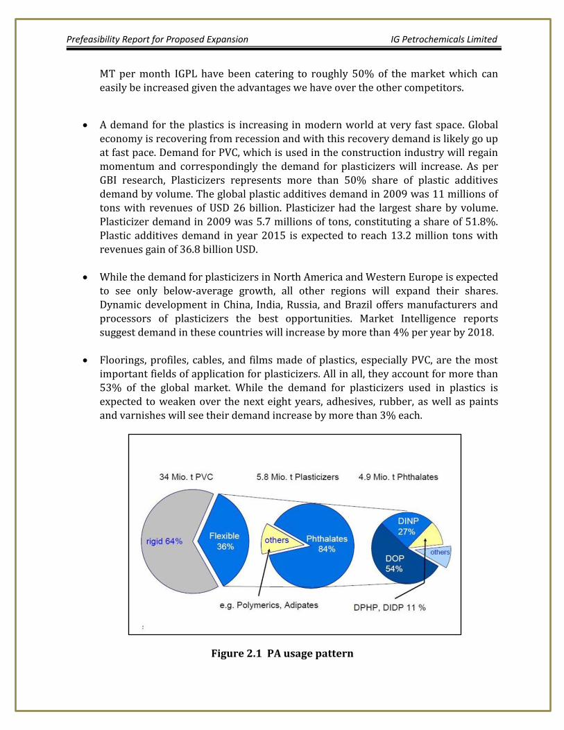
A demand for the plastics is increasing in modern world at very fast space. Global economy is recovering from recession and with this recovery demand is likely go up at fast pace. Demand for PVC, which is used in the construction industry will regain momentum and correspondingly the demand for plasticizers will increase. As per GBI research, Plasticizers represents more than 50% share of plastic additives demand by volume. The global plastic additives demand in 2009 was 11 millions of tons with revenues of USD 26 billion. Plasticizer had the largest share by volume.
Plasticizer demand in 2009 was 5.7 millions of tons, constituting a share of 51.8%. Plastic additives demand in year 2015 is expected to reach 13.2 million tons with revenues gain of 36.8 billion USD.
While the demand for plasticizers in North America and Western Europe is expected to see only below-average growth, all other regions will expand their shares. Dynamic development in China, India, Russia, and Brazil offers manufacturers and processors of plasticizers the best opportunities. Market Intelligence reports suggest demand in these countries will increase by more than 4% per year by 2018.
Floorings, profiles, cables, and films made of plastics, especially PVC, are the most important fields of application for plasticizers. All in all, they account for more than 53% of the global market. While the demand for plasticizers used in plastics is expected to weaken over the next eight years, adhesives, rubber, as well as paints and varnishes will see their demand increase by more than 3% each.
Figure 2.1 PA usage pattern
Prefeasibility Report for Proposed Expansion IG Petrochemicals Limited
Export Possibility 2.5
Based on market growing demand projections there is great opportunity for export.
Employment Generation due to Project (Direct and indirect) 2.6
The project will have major employment generation in terms of direct (60 nos) and
contract employment (45 nos). Total employment about 105 Nos.
Prefeasibility Report for Proposed Expansion IG Petrochemicals Limited
PROJECT DESCRIPTION 3
Type of Project including interlinked or interdependent projects, if 3.1any
It is expansion project of petrochemicals of existing and new synthetic organic chemicals as mentioned above in chapter 2. The project is interlinked with downstream recovery of Maleic Anhydride from scrubber wash water by Mysore Petrochemicals limited (sister concern of IGPL , neighboring unit).
Location of the Project 3.2
Table 3-1 Details Of Nearest Infrastructure Facilities
Sr. No Destination App. Distance of Project Site
1 Nearest National Highway
NH-4 4 km
2 Nearest Airport
Mumbai 28 km
3 Nearest Railway Station
Taloje Panchnand 4.5 km
4 Nearest Port
JNPT sea port 30 km
The proposed expansion is on the existing location at plot no. T-2 and the adjacent acquired plot T- 2 (part) at MIDC Industrial Estate, Taloja, Dist Raigad Maharashtra. The Geographical Location of this Industry is at coordinates, 190 05’ 27”N and 730 7’41”E
at elevation above Mean sea level of 25 meters. This site is in premises of MIDC which is meant for these types of Industries. GPS Location on Google Imagery of the proposed site is attached for as (Annexure I). Land Form: Land is on plain contour, it is flat terrain. Land Ownership: Land ownership is with project proponents (IG Petrochemicals limited).
Existing Land use Pattern: The Land is reserved for Industrial use & presently project expansion site is at the same plot. MIDC Taloja is a multi-product industrial estate
Prefeasibility Report for Proposed Expansion IG Petrochemicals Limited
Existing Infrastructure: Presently there is an existing Infrastructure at the site. Infrastructure like water, electricity, telephone facility, roads already available as this is an existing Industrial area. There is no sensitive establishment in the vicinity such as health resort, hospital, archaeological monuments, Wild Life Sanctuaries, National Parks etc.
The location justification for the project is as under 3.3
a. Availability of required land and infrastructure for locating the expansion and integration with existing facility.
b. Suitability of land from topography & geological aspects, synergy and business point of view
c. Proximity to rail / road to facilitate transport of equipment / materials/ product d. Availability of adequate quantity of water to meet water requirements.
Lay-Out 3.4
Refer Annexure II for the plant site layout plan.
Project Description with Processes Details: 3.5
Manufacturing Process: Broad manufacturing process of the chemicals is given below.
Phthalic anhydride 3.5.1
The process technology for proposed Phthalic Anhydride plant & improving recovery of Benzoic Acid plant is being provided by PA consultants, GMBH of Germany. The raw material required for manufacturing Phthalic Anhydride is oxygen which is drawn from atmospheric air & O-Xylene. O-Xylene from storage tank is filtered in two stages, pre heated
to about 1350 to 140oC & fed to O-Xylene air mixer through specially designed spray nozzles to have very fine droplets for effective evaporation followed by uniform concentration of O-Xylene in the mixture. The mixture of O-Xylene & air is fed to fixed bed tubular reactor filled with catalyst (V2O5 / TiO2 on ceramic rings). The reaction of O-Xylene to Phthalic Anhydride is exothermic in nature which is removed by continuous circulation of heat transfer salt. The heat of reaction is removed in a salt bath cooler where heat is exchanged between salt and feed water connected to a waste heat boiler for generating steam in the range 50 to 60 barg & super heating the steam used for operating steam turbine for power generation.
The gas leaving the reactor is at a temperature of 340 to 380oC depending on the heat transfer salt temperature maintained in the reactor which increases gradually from start of
Prefeasibility Report for Proposed Expansion IG Petrochemicals Limited
catalyst run to end catalyst run and is passed through GASCAT which has cooling arrangements to cool the gas and also adiabatic reactor which converts under oxidized product and traces of O-Xylene from reactor into phthalic anhydride. The gas from reactor is cooled in two stages initially to bring down the temperature to about 280 330oC by passing saturated steam through the first bundle & in the second bundle, 50-60 bar (g) steam is generated. The gas stream passes through catalyst bed where under oxidation products and O-Xylene slippage will be converted to Phthalic Anhydride & other low boiling impurities will be oxidized. The gas stream is further cooled in the third stage where process energy is utilized is used for pre heating the feed water which is required for waste heat boiler.
The gas from GASCAT is fed to partial condenser where phthalic anhydride partially condenses and the gas outlet temperature is reduced to about 134 to 138 Deg C. The gas then passes to battery of switch condensers (4 numbers) for recovering Phthalic Anhydride from gaseous stream. Switch condensers are finned tube heat exchangers circulated with cold or hot heat transfer oil through tubes of each switch condenser depending on their modes in the cycle. The switch condensers are operated such that 3 numbers of switch condensers are in gas receiving mode, one switch condenser is under melting or in re cooling mode. Cold heat transfer oil at a temperature of 55 to 60oC is circulated through switch condenser for de sublimating Phthalic Anhydride from gaseous stream. Phthalic Anhydride sublimes on the fin surfaces in the switch condenser & the off gas which leaves
switch condenser chiefly contains Maleic Anhydride, with other impurities such as Benzoic acid, Citraconic Anhydride, Phthalide and traces of Phthalic Anhydride. The switch condenser after loading for a specified time isolates automatically from the system based on predefined program in DCS & hot heat transfer oil at a temperature of 150 to 200oC is circulated to melt Phthalic Anhydride sublimated on fins surface & drain the crude Phthalic Anhydride to storage vessel. The off gas from switch condenser is scrubbed with DM water in three stage scrubber having a demister at the outlet of scrubber, to remove traces of acid mist from the off gas before it is discharged to atmosphere through 50 m high chimney. The scrubbed water
called wash water is concentrated to the required level and is sent for Phthalic Acid & Benzoic Acid in recovery plant & the filtrate is sent to M/s Mysore Petrochemicals limited (adjacent unit) through pipe line for recovery of Maleic Anhydride. In the purification section, crude Phthalic Anhydride is preheated to about 225oC & fed dehydrator mounted on the top of pretreatment vessel with condenser. Phthalic Acid in the crude Phthalic Anhydride dehydrates & later flows to pretreatment vessels. The temperature of Phthalic Anhydride is raised close to its boiling point, so that some of the low boiling components are removed &/or converted to high boiling components. After thermal pretreatment, crude Phthalic Anhydride from pretreatment vessels is fed to
forerunning column for separation of low boiling fraction. Low boiling fractions containing Phthalic Anhydride, Benzoic Acid & other low boiling impurities is drawn as overhead
Prefeasibility Report for Proposed Expansion IG Petrochemicals Limited
product and collected in the forerunning receiver. Phthalic Anhydride free from low boiling fraction is fed to pure Phthalic Anhydride column where pure Phthalic Anhydride is continuously drawn as overhead product & column bottom is fed continuously to equipment called Boil out vessel. The reflux from boil out vessel is sent back to pure Phthalic Anhydride column & or to crude Phthalic Anhydride storage vessel. After specified period, feed to boil out vessel is isolated & drained after concentration to High boiling storage receiver. The residue which is having a calorific value of about 5000 – 5500 Kcal/kg is fired in high temperature thermic fluid heater & thus no solid hazardous waste is generated.
The PA – IV Plant shall be identical to that of PA-III Plant except that it will have distillation section. The PA IV plant process technology shall be similar to that of existing Phthalic Anhydride Plants. In the proposed PA-IV plant, high pressure steam 50 – 60 bar (g) is used as heat energy for preheating crude Phthalic Anhydride as well as for reboilers in distillation column. The energy required for raising crude Phthalic Anhydride for thermal pretreatment & in high boilers separation in boil out vessel is supplied by heat transfer oil which is heated by firing the distillation back ends from Phthalic Anhydride plants and Maleic Anhydride plants and
the shortfall of fuel by furnace oil in the normal operation & diesel during startup of the fired heater. The PA IV plant will consist of Oxidation and sublimation section and distillation section for purification of crude Phthalic Anhydride. The process & utilities integration approach shall be followed for the proposed PA IV Plant for optimizing consumptions. The oxidation steam production from reactor of PA- IV shall be at higher pressure of 50 –
60 barg as against conventional 31 barg so that the same steam will be used in distillation sections in reboiler for heat energy & thus additional heat energy is required from heat transfer oil for distillation columns.
Recovery from Wash Water (Crystallization & BA recovery) 3.5.2
We have already established recovery of Benzoic Acid & Phthalic Acid from scrubber waste water before sending to adjacent sister concern M/s Mysore Petrochemicals Ltd for recovery of Maleic Anhydride & thus proposing similar way for recovery of PA & BA from PA-IV scrubber waste water also by increasing capacity of crystallizer. In the crystallization
process, difference in solubility of PA & BA in water by lowering temperature will be
Prefeasibility Report for Proposed Expansion IG Petrochemicals Limited
utilized to achieve for separation by crystallizing the less soluble PA & BA from the wash water solution. The waste water from scrubber from existing PA-I/ II/ III plants & proposed PA-IV containing Phthalic anhydride (PA), Benzoic acid (BA) & other impurities will be subjected to lower temperature with required residence time thereby partly crystallizing the two products depending on solubility at that operating temperature. The cooling will be achieved by evaporating water from the wash water solution at high vacuum. The remaining solution will then be fed to pressure rotary filter thereby separating the wash water and BA+PA crystals (cake). The cake of crystals thus formed of BA+PA crystals is
dehydrated & sent to recovery in a BA recovery column. Filtrate from pressure rotary filter will be sent for MA recovery to our neighboring sister concern M/s Mysore Petrochemicals Ltd.
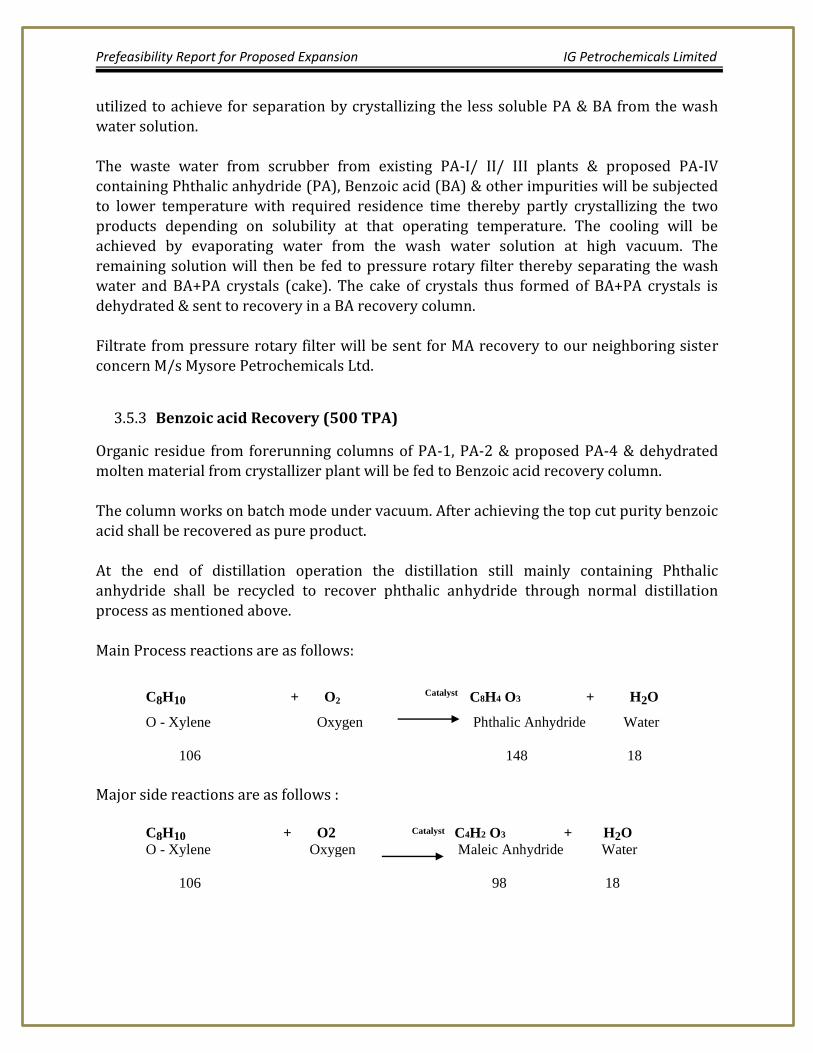
Benzoic acid Recovery (500 TPA) 3.5.3
Organic residue from forerunning columns of PA-1, PA-2 & proposed PA-4 & dehydrated molten material from crystallizer plant will be fed to Benzoic acid recovery column.
The column works on batch mode under vacuum. After achieving the top cut purity benzoic acid shall be recovered as pure product. At the end of distillation operation the distillation still mainly containing Phthalic anhydride shall be recycled to recover phthalic anhydride through normal distillation process as mentioned above. Main Process reactions are as follows:
C8H10 + O2 Catalyst C8H4 O3 + H2O
O - Xylene Oxygen Phthalic Anhydride Water
106 148 18
Major side reactions are as follows :
C8H10 + O2 Catalyst C4H2 O3 + H2O
O - Xylene Oxygen Maleic Anhydride Water
106 98 18
Prefeasibility Report for Proposed Expansion IG Petrochemicals Limited
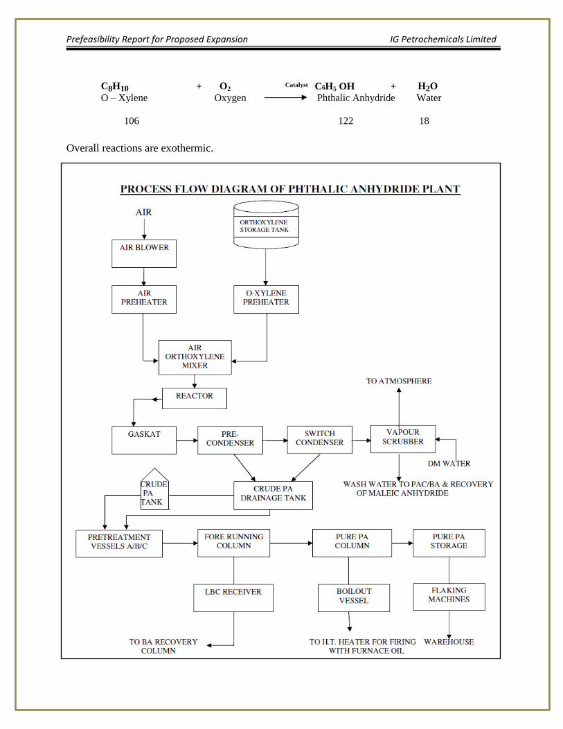
C8H10 + O2 Catalyst C6H5 OH + H2O
O – Xylene Oxygen Phthalic Anhydride Water
106 122 18
Overall reactions are exothermic.
Prefeasibility Report for Proposed Expansion IG Petrochemicals Limited
ISBL: 3.5.4
3.5.4.1 Oxidation section: Main equipment are
Reactor, turbine for generating power & to drive blower for supply of air for partial oxidation of O-Xylene, heat exchangers for cooling & heating as per process, waste heat recovery boilers, O-Xylene day tank, partial condenser, switch condensers, scrubber, crude storage vessel & tank, heat transfer oil system for cold & hot oil & air ejectors & required pumps.
3.5.4.2 Distillation Section: Main equipment are
Crude Phthalic Anhydride preheater, pretreatment vessels, columns, steam powered reboilers, condenser, heat exchangers, pure Phthalic Anhydride storage vessels & tank, fired heater for supply of heat energy to heat transfer oil, flakers.
BB- Offsite (OSBL) 3.5.5
3.5.5.1 Raw Material Storage tanks
Existing O-Xylene storage capacity is adequate & thus no addition of raw material storage for proposed PA-4.
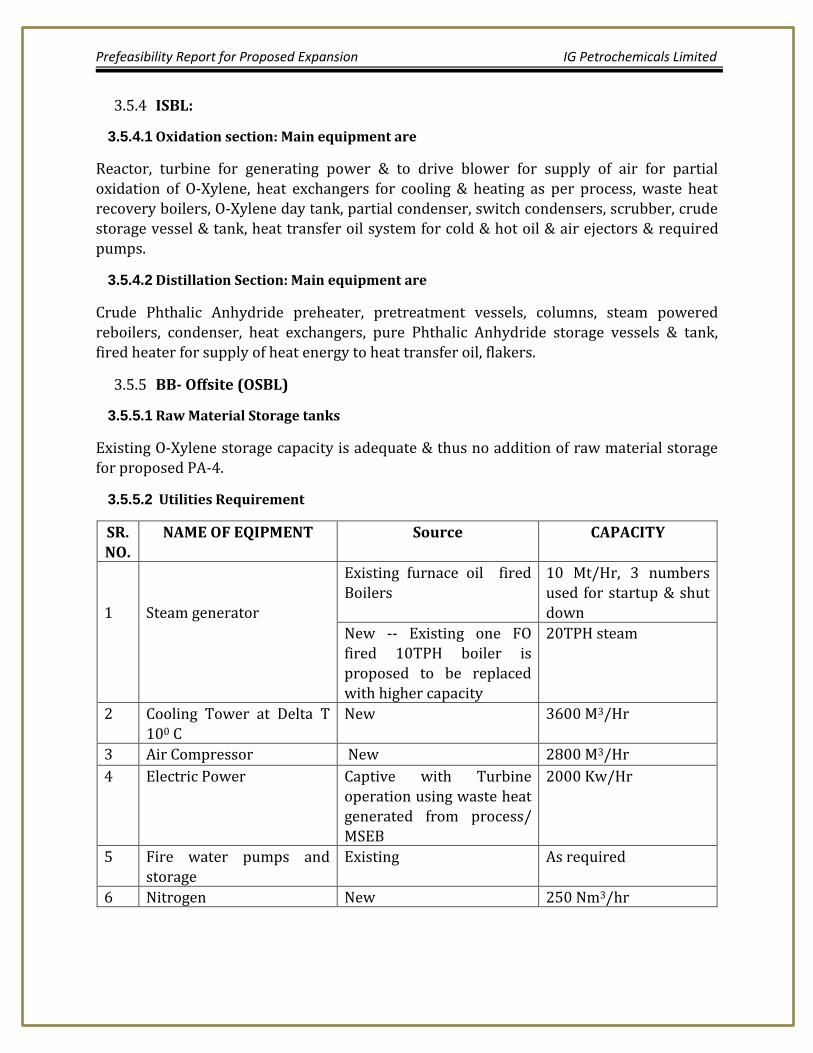
3.5.5.2 Utilities Requirement
SR. NO.
NAME OF EQIPMENT Source CAPACITY
1
Steam generator
Existing furnace oil fired Boilers
10 Mt/Hr, 3 numbers used for startup & shut down
New -- Existing one FO fired 10TPH boiler is proposed to be replaced with higher capacity
20TPH steam
2 Cooling Tower at Delta T 100 C
New 3600 M3/Hr
3 Air Compressor New 2800 M3/Hr
4 Electric Power Captive with Turbine operation using waste heat generated from process/ MSEB
2000 Kw/Hr
5 Fire water pumps and storage
Existing As required
6 Nitrogen New 250 Nm3/hr
Prefeasibility Report for Proposed Expansion IG Petrochemicals Limited
Plasticizers 3.6
Di-Octyl Phthalate (DOP) 3.6.1
Chemical name: Di-2 Ethyl Hexyl Phthalate (DEHP)
3.6.1.1 Process Description
Di-Octyl Phthalate is produced by esterification of Phthalic Anhydride by 2-Ethyl Hexyl Alcohol in presence of a catalyst.
The reaction is as follows:
C8H4 O3 + 2C8H17OH
Catalyst
C24H38O4 + H2O Phthalic
anhydride 2 Ethyl Hexanol Di Octyl Phthalate Water 148 260 390 18
Overall reaction is endothermic.
The process uses two stage reactions where in first stage 2-Ethyl Hexyl Alcohol esterifies Phthalic Anhydride in presence of a catalyst in reactor (under vacuum) and in second stage the excess alcohol is recovered, acidity is removed by neutralization and then dehydrated under vacuum. The dehydrated material is then filtered off. The detail process is as follows
3.6.1.2 1st Stage: Reactor
Charge recovered alcohol. Put the system under vacuum and heat up to 1000c to dehydrate, when dehydration is complete charge the balance of fresh alcohol. Start the addition of melted Phthalic Anhydride (PAN). This addition must be completed in 50 mins. The heating
is started simultaneously. When the PAN is added completely, close and tight the manhole. Continue heating put one by one separator in circuit and attain the temp. of 155- 1600c. Apply vacuum and start addition of catalyst. Remove the vacuum and continue the heating. The refluxing of alcohol and water vapor will start at temperature 165 to 1700c. The alcohol and water is continuously goes on collecting to separator. The alcohol is continuously returned back to the reactor and water is continuously removed from bottom valve of the separator. When pre calculated quantity of water is removed, vacuum is applied to the system slowly. The heating is continued. The vacuum is increased slowly to 700 -710 mm taking care that no flooding is observed. When vacuum reaches to 700 mm Hg the acid value of the sample from reactor is checked. When desired acid value comes,
alcohol collection is diverted to recovery receiver. The vacuum (710 mm Hg) and desired temp. is maintained till acid value reduces to 0.1 to 0.2. When acid value reaches to 0.1 – 0.2
Prefeasibility Report for Proposed Expansion IG Petrochemicals Limited
the reaction mass is steam stripped under vacuum. While stripping the temperature drops down Apply heating and heat to desired temp. Put the system under full vacuum. Continue steam (Steam pressure 7 - 8 kg/cm2) through spurger of the Reactor. Azeotropic distillation of alcohol will start and alcohol water mixture collects in its separator. Maintain the temperature and continue stripping for 2-3 hrs. Check the color and acid value. Release the vacuum by Nitrogen gas and transfer mass to neutralizer. Meanwhile prepare the solution of caustic in Caustic dissolver by adding appropriate quantity of Caustic flakes in water.
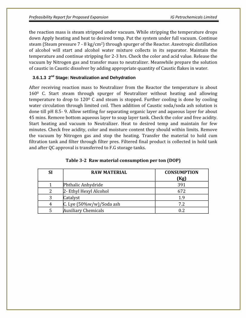
3.6.1.3 2nd Stage: Neutralization and Dehydration
After receiving reaction mass to Neutralizer from the Reactor the temperature is about
1600 C. Start steam through spurger of Neutralizer without heating and allowing temperature to drop to 1200 C and steam is stopped. Further cooling is done by cooling water circulation through limited coil. Then addition of Caustic soda/soda ash solution is done till pH 8.5- 9. Allow settling for separating organic layer and aqueous layer for about 45 mins. Remove bottom aqueous layer to soap layer tank. Check the color and free acidity. Start heating and vacuum to Neutralizer. Heat to desired temp and maintain for few minutes. Check free acidity, color and moisture content they should within limits. Remove the vacuum by Nitrogen gas and stop the heating. Transfer the material to hold cum filtration tank and filter through filter pres. Filtered final product is collected in hold tank and after QC approval is transferred to F.G storage tanks.
Table 3-2 Raw material consumption per ton (DOP)
SI RAW MATERIAL CONSUMPTION (Kg)
1 Phthalic Anhydride 391
2 2- Ethyl Hexyl Alcohol 672
3 Catalyst 1.9
4 C. Lye (50%w/w)/Soda ash 7.2
5 Auxiliary Chemicals 0.2
Prefeasibility Report for Proposed Expansion IG Petrochemicals Limited
BLOCK DIAGRAM OF DOP/DIOP/DINP/DIDP/DBP/DIBP MANUFACTURING
Figure 3.1 Block Diagram of DOP/DIOP/DIDP/DBP/DIBP Manufacturing
Two trains are built for producing plasticizers and products will be manufactured on campaign basis in the setup as shown in the block diagram.
Di-Iso Octyl Phthalate (DIOP) 3.6.2
Chemical name: Di-Iso Octyl Phthalate (DIOP) Process Description
Di-Iso Octyl Phthalate is produced by esterification of Phthalic Anhydride by Iso Octyl Alcohol in presence of a catalyst. The reaction is as follows:
C8H4 O3 + 2C8H17OH
C24H38 O4 + H2O
Catalyst
Phthalic anhydride
Iso Octyl Alcohol
Di –Iso Octyl Phthalate Water
148 260 390 18 Overall reaction is endothermic.
Prefeasibility Report for Proposed Expansion IG Petrochemicals Limited
The process uses two stage reactions where in first stage Iso Octyl Alcohol esterifies Phthalic Anhydride in presence of a catalyst in reactor (under vacuum) and in second stage the excess alcohol is recovered, acidity is removed by neutralization and then dehydrated under vacuum. The dehydrated material is then filtered off. The detail process is same as DOP.
Table 3-3 Raw material consumption per ton (DIOP)
SI RAW MATERIAL CONSUMPTION (Kg)
1 Phthalic Anhydride 391
2 Iso Octanol 674
3 Catalyst 1.9
4 C. Lye (50%w/w)/Soda Ash 7.2
5 Auxiliary Chemicals 0.2
Di-Iso Nonyl Phthalate (DINP) 3.6.3
Chemical name: Di-Iso Nonyl Phthalate (DINP) Process Description
Di-Iso Nonyl Phthalate is produced by etherification of Phthalic Anhydride by Iso Nonyl Alcohol in presence of a catalyst. The reaction is as follows:
C8H4 O3 + 2C9H19OH
C26H42 O4 + H2O
Catalyst
Phthaic anhydride Iso Nonyl Alcohol Di –Iso Nonyl Phthalate Water 148 288 418 18
Overall reaction is endothermic.
The process uses two stage reactions where in first stage Iso Nonyl Alcohol esterifies Phthalic Anhydride in presence of a catalyst in reactor (under vacuum) and in second stage the excess alcohol is recovered, acidity is removed by neutralization and then dehydrated under vacuum. The dehydrated material is then filtered off. The detail process is same as DOP.
Prefeasibility Report for Proposed Expansion IG Petrochemicals Limited
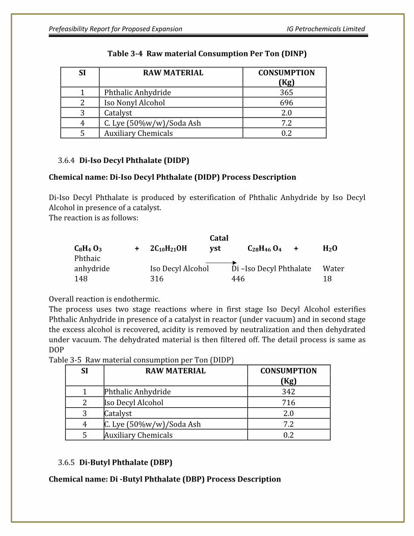
Table 3-4 Raw material Consumption Per Ton (DINP)
SI RAW MATERIAL CONSUMPTION (Kg)
1 Phthalic Anhydride 365
2 Iso Nonyl Alcohol 696 3 Catalyst 2.0
4 C. Lye (50%w/w)/Soda Ash 7.2 5 Auxiliary Chemicals 0.2
Di-Iso Decyl Phthalate (DIDP) 3.6.4
Chemical name: Di-Iso Decyl Phthalate (DIDP) Process Description
Di-Iso Decyl Phthalate is produced by esterification of Phthalic Anhydride by Iso Decyl Alcohol in presence of a catalyst. The reaction is as follows:
C8H4 O3 + 2C10H21OH
C28H46 O4 + H2O
Catalyst
Phthaic
anhydride Iso Decyl Alcohol Di –Iso Decyl Phthalate Water 148 316 446 18
Overall reaction is endothermic. The process uses two stage reactions where in first stage Iso Decyl Alcohol esterifies Phthalic Anhydride in presence of a catalyst in reactor (under vacuum) and in second stage the excess alcohol is recovered, acidity is removed by neutralization and then dehydrated under vacuum. The dehydrated material is then filtered off. The detail process is same as DOP Table 3-5 Raw material consumption per Ton (DIDP)
SI RAW MATERIAL CONSUMPTION (Kg)
1 Phthalic Anhydride 342
2 Iso Decyl Alcohol 716
3 Catalyst 2.0
4 C. Lye (50%w/w)/Soda Ash 7.2
5 Auxiliary Chemicals 0.2
Di-Butyl Phthalate (DBP) 3.6.5
Chemical name: Di -Butyl Phthalate (DBP) Process Description
Prefeasibility Report for Proposed Expansion IG Petrochemicals Limited
Di-Butyl Phthalate is produced by esterification of Phthalic Anhydride by Normal Butyl Alcohol in presence of a catalyst. The reaction is as follows:
C8H4 O3 + 2C4H9OH
C16H22 O4 + H2O
Catalyst Phthalic anhydride
Normal Butyl Alcohol
Di Butyl Phthalate Water
148 148 278 18 Overall reaction is endothermic.
The process uses two stage reactions where in first stage Normal Butyl Alcohol esterifies Phthalic Anhydride in presence of a catalyst in reactor and in second stage the excess alcohol is recovered, acidity is removed by neutralization and then dehydrated under vacuum. The dehydrated material is then filtered off. The detail process is same as bellow. The detail process is as follows
3.6.5.1 1st Stage: Reactor
Charge recovered alcohol. Put the system under vacuum and heat up to 1000c to dehydrate,
when dehydration is complete charge the balance of fresh alcohol. Start the addition of flaked Phthalic Anhydride (PAN). The heating is started simultaneously. When the PAN is added completely, close and fit the manhole. Continue heating The refluxing of alcohol and water vapor will start at temperature 135 to 1450c. The alcohol and water is continuously goes on collecting to separator. The alcohol is continuously returned back to the reactor and water is continuously removed from bottom valve of the separator. When pre calculated quantity of water is removed, vacuum is applied to the system slowly. The heating is continued. When temperature reaches to155 to 1600c slowly add pre calculated quantity of fresh alcohol from dosing tank. The quantity is calculated based on A.V. Heating is continued and A.V. is checked after every 30 mins, When A.V. reaches to 2.2 -2.3 flow of
condensing alcohol is diverted to recovery receiver and vacuum is applied to reactor via
this receiver. The vacuum is increased slowly to 700 -710 mm taking care that no flooding is observed. When vacuum reaches to 700 mm Hg the acid value of the sample from reactor is checked. When A.V reaches 1.2 - 1.3, vacuum is released by Nitrogen and the reaction mass is transferred to neutralizer. and transfer mass to neutralizer. Meanwhile prepare the solution of caustic in Caustic dissolver by adding appropriate quantity of Caustic flakes in water.
3.6.5.2 2nd Stage: Neutralization and Dehydration
After receiving reaction mass to Neutralizer from the Reactor the temperature is about 150-1550 C. Start cooling by circulating cooling water through limpitted coil. Then addition
of Caustic soda solution is done till pH 8.5 - 9. Allow settling for separating organic layer
Prefeasibility Report for Proposed Expansion IG Petrochemicals Limited
and aqueous layer for about 45 mins. Remove bottom aqueous layer to soap layer tank. Check the color and free acidity. Start heating and vacuum to Neutralizer. Apply vacuum and heat the reaction mass to 1500 C and start steam through spurger for stripping. While stripping the temperature drops down Apply heating and heat to desired temp. Put the system under full vacuum. Continue steam (Steam pressure 7- 8 kg/cm2) through Spurger of the. Azeotropic distillation of alcohol will start and alcohol water mixture collects in its separator. Maintain the temperature and continue stripping for 2- 3 hrs. Stop steam purging, check the color and acid value. Heat to desired temp and maintain for few minutes. Check free acidity, color and moisture content they should within limits. Remove the vacuum by Nitrogen gas and stop the heating. Transfer the material to hold cum filtration
tank and filter through filter pres. Filtered final product is collected in hold tank and after QC approval is transferred to F.G storage tanks.
Table 3-6 Raw material consumption Per Ton (DBP)
SI RAW MATERIAL CONSUMPTION (Kg)
1 Phthalic Anhydride 548
2 Normal Butyl Alcohol 560
3 Catalyst 2.8
4 C. Lye (50%w/w)/Soda Ash 7.2
5 Auxiliary Chemicals 0.2
Di-Iso Butyl Phthalate (DIBP) 3.6.6
Chemical name: Di-Iso Butyl Phthalate (DIBP) Process Description Di-Iso Butyl Phthalate is produced by esterification of Phthalic Anhydride by Iso Butyl Alcohol in presence of a catalyst.
The reaction is as follows:
C8H4 O3 + 2C4H9OH
C16H22 O4 + H2O
Catalyst
Phthalic anhydride
Iso Butyl Alcohol
Di Iso Butyl Phthalate Water
148 148 278 18 Overall reaction is endothermic.
The process uses two stage reactions where in first stage Iso Butyl Alcohol esterifies Phthalic Anhydride in presence of a catalyst in reactor and in second stage the excess
Prefeasibility Report for Proposed Expansion IG Petrochemicals Limited
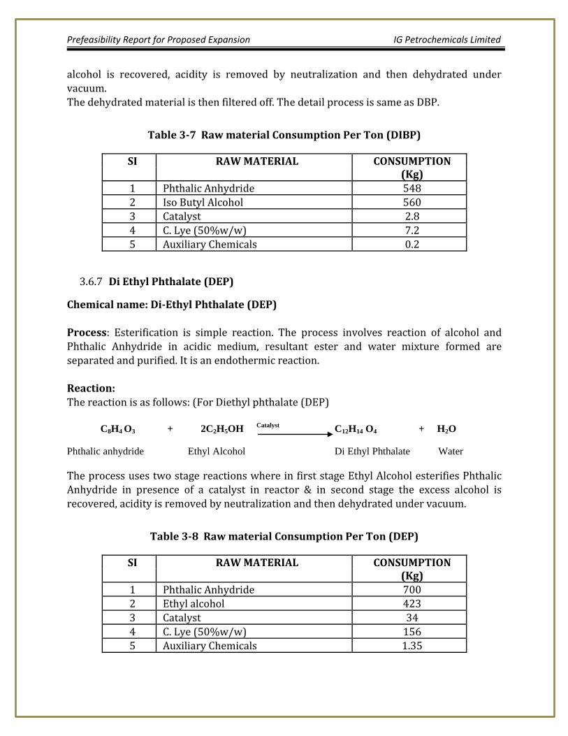
alcohol is recovered, acidity is removed by neutralization and then dehydrated under vacuum. The dehydrated material is then filtered off. The detail process is same as DBP.
Table 3-7 Raw material Consumption Per Ton (DIBP)
SI RAW MATERIAL CONSUMPTION (Kg)
1 Phthalic Anhydride 548
2 Iso Butyl Alcohol 560
3 Catalyst 2.8
4 C. Lye (50%w/w) 7.2 5 Auxiliary Chemicals 0.2
Di Ethyl Phthalate (DEP) 3.6.7
Chemical name: Di-Ethyl Phthalate (DEP) Process: Esterification is simple reaction. The process involves reaction of alcohol and Phthalic Anhydride in acidic medium, resultant ester and water mixture formed are
separated and purified. It is an endothermic reaction. Reaction: The reaction is as follows: (For Diethyl phthalate (DEP) C8H4 O3 + 2C2H5OH
Catalyst C12H14 O4 + H2O
Phthalic anhydride Ethyl Alcohol Di Ethyl Phthalate Water
The process uses two stage reactions where in first stage Ethyl Alcohol esterifies Phthalic Anhydride in presence of a catalyst in reactor & in second stage the excess alcohol is
recovered, acidity is removed by neutralization and then dehydrated under vacuum.
Table 3-8 Raw material Consumption Per Ton (DEP)
SI RAW MATERIAL CONSUMPTION (Kg)
1 Phthalic Anhydride 700 2 Ethyl alcohol 423
3 Catalyst 34
4 C. Lye (50%w/w) 156
5 Auxiliary Chemicals 1.35
Prefeasibility Report for Proposed Expansion IG Petrochemicals Limited
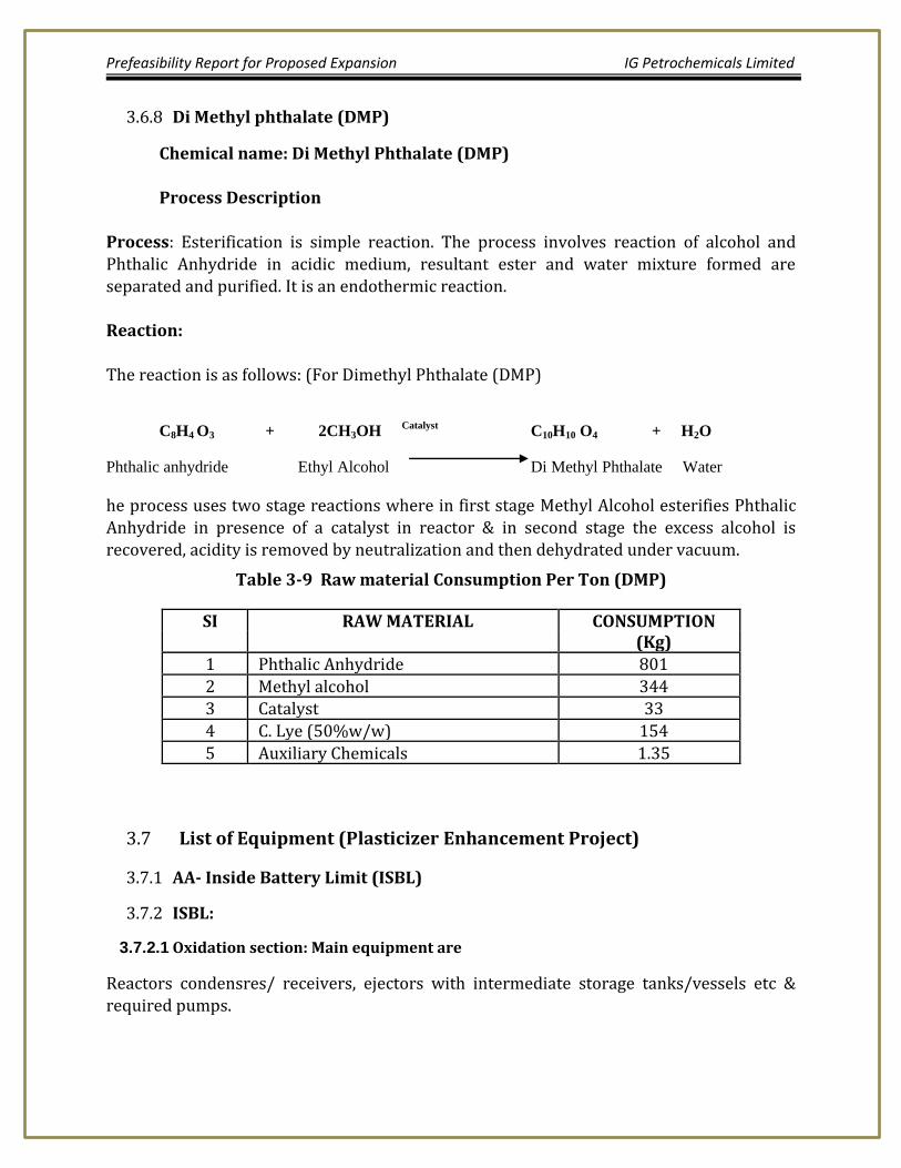
Di Methyl phthalate (DMP) 3.6.8
Chemical name: Di Methyl Phthalate (DMP)
Process Description Process: Esterification is simple reaction. The process involves reaction of alcohol and Phthalic Anhydride in acidic medium, resultant ester and water mixture formed are separated and purified. It is an endothermic reaction. Reaction:
The reaction is as follows: (For Dimethyl Phthalate (DMP)
C8H4 O3 + 2CH3OH Catalyst
C10H10 O4 + H2O
Phthalic anhydride Ethyl Alcohol Di Methyl Phthalate Water
he process uses two stage reactions where in first stage Methyl Alcohol esterifies Phthalic Anhydride in presence of a catalyst in reactor & in second stage the excess alcohol is recovered, acidity is removed by neutralization and then dehydrated under vacuum.
Table 3-9 Raw material Consumption Per Ton (DMP)
SI RAW MATERIAL CONSUMPTION (Kg)
1 Phthalic Anhydride 801
2 Methyl alcohol 344 3 Catalyst 33
4 C. Lye (50%w/w) 154
5 Auxiliary Chemicals 1.35
List of Equipment (Plasticizer Enhancement Project) 3.7
Carbon treatment, Filter press and associated equipments.
BB- Offsite (OSBL) 3.7.3
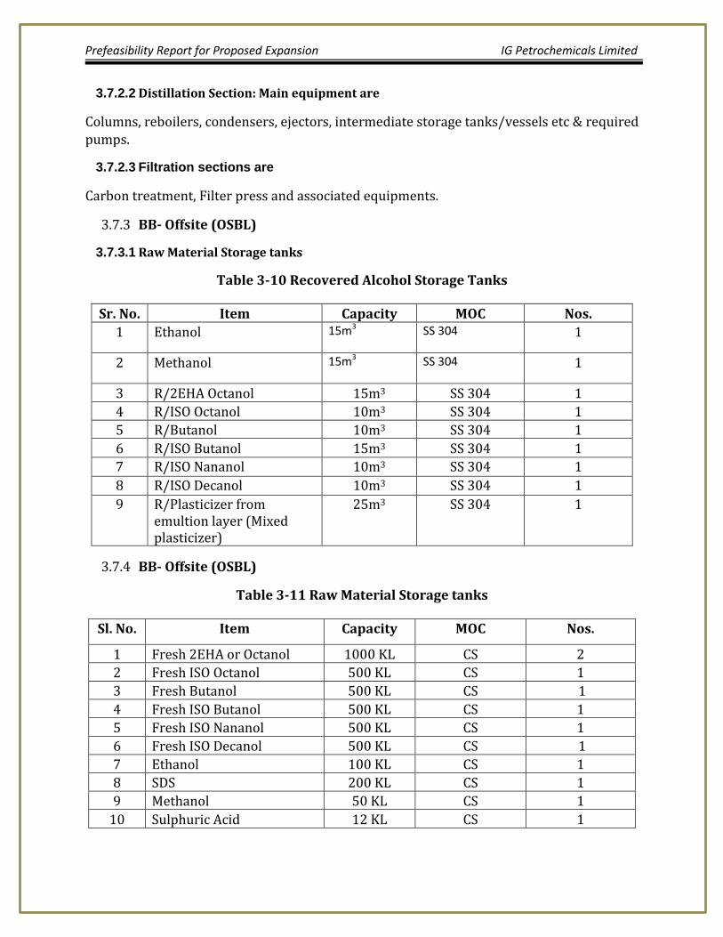
3.7.3.1 Raw Material Storage tanks
Table 3-10 Recovered Alcohol Storage Tanks
Sr. No. Item Capacity MOC Nos.
1 Ethanol 15m3 SS 304 1
2 Methanol 15m3 SS 304 1
3 R/2EHA Octanol 15m3 SS 304 1
4 R/ISO Octanol 10m3 SS 304 1
5 R/Butanol 10m3 SS 304 1
6 R/ISO Butanol 15m3 SS 304 1
7 R/ISO Nananol 10m3 SS 304 1
8 R/ISO Decanol 10m3 SS 304 1
9 R/Plasticizer from emultion layer (Mixed plasticizer)
25m3 SS 304 1
BB- Offsite (OSBL) 3.7.4
Table 3-11 Raw Material Storage tanks
Sl. No. Item Capacity MOC Nos.
1 Fresh 2EHA or Octanol 1000 KL CS 2
2 Fresh ISO Octanol 500 KL CS 1
3 Fresh Butanol 500 KL CS 1
4 Fresh ISO Butanol 500 KL CS 1
5 Fresh ISO Nananol 500 KL CS 1
6 Fresh ISO Decanol 500 KL CS 1
7 Ethanol 100 KL CS 1
8 SDS 200 KL CS 1
9 Methanol 50 KL CS 1
10 Sulphuric Acid 12 KL CS 1
Prefeasibility Report for Proposed Expansion IG Petrochemicals Limited
Table 3-12 Final Product Storage tanks
Sl. No. Item Capacity MOC Nos.
1 DOP (Dioctyl Phthalate) 500 KL CS 2
2 DIBP (Di iso Butyl Phthalate 500 KL CS 1
3 DBP (Di-Butyl Phthalate) 150 KL CS 1
4 DINP (Di-iso Nanyl Phthalate) 150 KL CS 1
5 DINP (Di-iso decyl Phthalate) 150 KL CS 1
6 DIOP (Di-iso Octyl Phthalate) 150 KL CS 1
7 DEP (DI-Ethyl Phthalate) 50 KL SS 304 1
8 DEP/DMP 30 KL SS 304 2
Table 3-13 UTILITIES REQUIREMENT
SR. NO.
NAME OF EQIPMENT Source CAPACITY
1 Steam New one Coal fired Boiler
15 Mt/hr@ 35 bar pressure Coal requirement – 72 MTPD or
Biomass Briquette 84 MTPD
2 Cooling Tower at Delta T 100C
Existing 500 M3/Hr
3 Air Compressor From PA-4 500 NM3/Hr
4 Electric Power Existing from captive power & MSEB
750 Kwh/Hr
5 Fire water pumps and storage
Existing As required
6 Nitrogen PA-4 As required
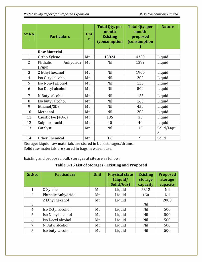
Table 3-14 List of Major Indicative raw Material requirement & their Nature
Prefeasibility Report for Proposed Expansion IG Petrochemicals Limited
Sr.No.
Particulars Uni
t
Total Qty. per month
Existing (consumption
)
Total Qty. per month
proposed (consumption
)
Nature
Raw Material
1 Ortho Xylene Mt 13824 4320 Liquid
2 Phthalic Anhydride (PAN)
Mt Nil 1392 Liquid
3 2 Ethyl hexanol Mt Nil 1900 Liquid
4 Iso Octyl alcohol Mt Nil 200 Liquid
5 Iso Nonyl alcohol Mt Nil 125 Liquid
6 Iso Decyl alcohol Mt Nil 500 Liquid
7 N Butyl alcohol Mt Nil 155 Liquid
8 Iso butyl alcohol Mt Nil 160 Liquid
9 Ethanol/SDS Mt Nil 450 Liquid
10 Methanol Mt Nil 200 Liquid
11 Caustic lye (48%) Mt 135 35 Liquid
12 Sulphuric acid Mt 40 40 Liquid
13 Catalyst Mt Nil 10 Solid/Liquid
14 Other Chemical Mt 1.6 9 Solid
Storage: Liquid raw materials are stored in bulk storages/drums. Solid raw materials are stored in bags in warehouse. Existing and proposed bulk storages at site are as follow:
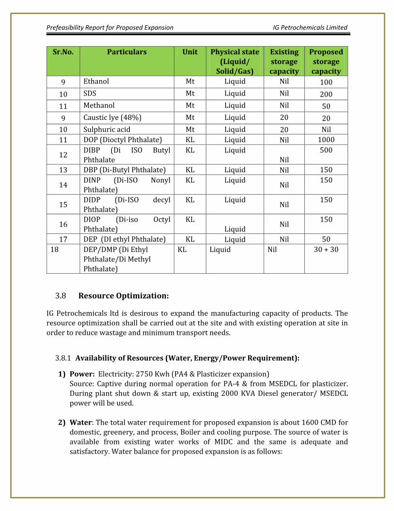
Table 3-15 List of Storages - Existing and Proposed
Sr.No. Particulars Unit Physical state
(Liquid/ Solid/Gas)
Existing
storage capacity
Proposed
storage capacity
1 O Xylene Mt Liquid 8612 Nil
2 Phthalic Anhydride Mt Liquid 150 Nil
3 2 Ethyl hexanol Mt Liquid
Nil 2000
4 Iso Octyl alcohol Mt Liquid Nil 500
5 Iso Nonyl alcohol Mt Liquid Nil 500
6 Iso Decyl alcohol Mt Liquid Nil 500
7 N Butyl alcohol Mt Liquid Nil 500
8 Iso butyl alcohol Mt Liquid Nil 500
Prefeasibility Report for Proposed Expansion IG Petrochemicals Limited
IG Petrochemicals ltd is desirous to expand the manufacturing capacity of products. The resource optimization shall be carried out at the site and with existing operation at site in order to reduce wastage and minimum transport needs.
Availability of Resources (Water, Energy/Power Requirement): 3.8.1
1) Power: Electricity: 2750 Kwh (PA4 & Plasticizer expansion) Source: Captive during normal operation for PA-4 & from MSEDCL for plasticizer. During plant shut down & start up, existing 2000 KVA Diesel generator/ MSEDCL power will be used.
2) Water: The total water requirement for proposed expansion is about 1600 CMD for
domestic, greenery, and process, Boiler and cooling purpose. The source of water is available from existing water works of MIDC and the same is adequate and
satisfactory. Water balance for proposed expansion is as follows:
Prefeasibility Report for Proposed Expansion IG Petrochemicals Limited
Table 3-16 Fresh water intake
Sr No
Purpose for which it is consumed
Water consumption PA-4 (CMD)
Water consumption Plasticizers Plant
(CMD)
Total fresh water Required
(CMD)
1 Domestic , Canteen etc. 10 10 20
2 Industrial Process
a) IGPL scrubber 30 30
b) Plasticizer plant 90 90
c) Floor washing 10 10 20
Industrial process (total)
160
3 Utilities
IGPL - Industrial cooling 1660
IGPL – WHRB + Steam boilers
190
Utilities (Total) 1850
4 Water treatment plant (back wash water)
Pressure sand filter back wash
10
DMW plant filter back wash
20
Back wash water (Total)
30
Grand Total 2040
Prefeasibility Report for Proposed Expansion IG Petrochemicals Limited
Table 3-17 Waste water
Sr No
Waste water source
Effluent generation
PA-4 (CMD)
Effluent generation Plasticizers
Plant (CMD)
**Effluent Generation from MA-4 (M/s
Mysore Petrochemicals Ltd,
sister concern MPCL) CMD
Total Effluent generati
on (CMD)
1 Domestic, Canteen etc.
8 8 2 18
2 Industrial Process
a) IGPL scrubber
b) Plasticizer plant 90 90
c) Floor washing 10 10 4 24
d) Column washing 17 17
Industrial process (total)
131
3 Utilities
Cooling tower
blow down
205
IGPL – Coal fired Steam boilers
10
Utilities (Total) 215
4 Water treatment plant (back wash water)
Pressure sand filter back wash
10
DMW plant filter back wash
20
Back wash water ( Total)
30
Grand Total 394 ** Note: Effluent generated from M/s MPCL is sent M/s IGPL for treatment.
Above effluent shall be treated at “existing upgraded ETP / new ETP” at IGPL and shall be
sent to CETP Taloja after the treatment.
3) Manpower: Additional manpower shall be required for the expansion project
which shall be recruited.
Prefeasibility Report for Proposed Expansion IG Petrochemicals Limited
Manpower scenario now and after expansion shall be as follows:
4) Steam / Process heat Requirement: The steam requirement and process heat
requirement for the proposed expansion shall be met from the exothermic heat of
the process similar to that of existing plants. There is proposal to add coal fired boiler as follows. Their proposed additional fuel requirement for coal fired boiler shall be as follows:
Table 3-19 The Proposed Additional Fuel Requirement for Coal Fired Boiler and
Existing DG set of total 2000 KVA is adequate for the expansion and hence there is no proposal to add any new DG set.
6) Proposed emission stacks
Sr
No
Description Stack Stack height
1 FO fired boiler 1 As per statutory guidelines
2 Coal fired boiler 1 As per statutory guidelines
3 Scrubber stack 1 50 m (similar to existing one)
4 Hot oil heater 1 As per statutory guidelines
Prefeasibility Report for Proposed Expansion IG Petrochemicals Limited
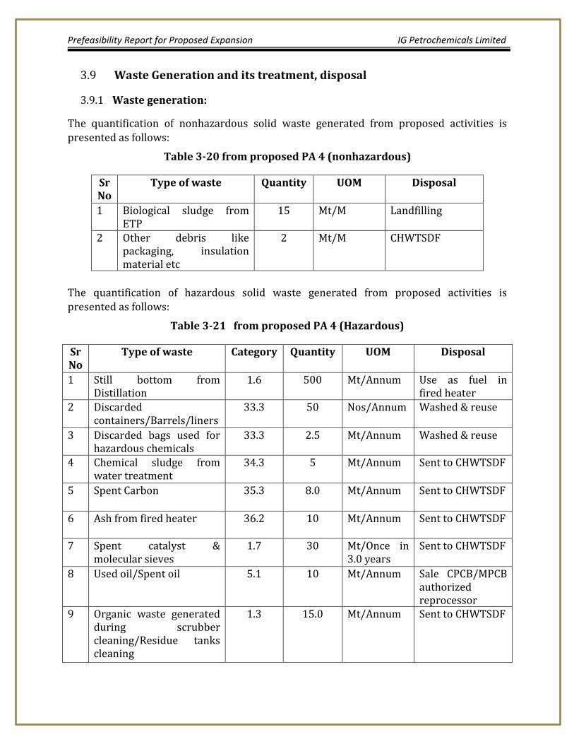
Waste Generation and its treatment, disposal 3.9
Waste generation: 3.9.1
The quantification of nonhazardous solid waste generated from proposed activities is presented as follows:
Table 3-20 from proposed PA 4 (nonhazardous)
Sr No
Type of waste Quantity UOM Disposal
1 Biological sludge from ETP
15 Mt/M Landfilling
2 Other debris like packaging, insulation material etc
2 Mt/M CHWTSDF
The quantification of hazardous solid waste generated from proposed activities is presented as follows:
Table 3-21 from proposed PA 4 (Hazardous)
Sr No
Type of waste Category Quantity UOM Disposal
1 Still bottom from Distillation
1.6 500 Mt/Annum Use as fuel in fired heater
2 Discarded containers/Barrels/liners
33.3 50 Nos/Annum Washed & reuse
3 Discarded bags used for hazardous chemicals
33.3 2.5 Mt/Annum Washed & reuse
4 Chemical sludge from water treatment
34.3 5 Mt/Annum Sent to CHWTSDF
5 Spent Carbon 35.3 8.0 Mt/Annum Sent to CHWTSDF
6 Ash from fired heater 36.2 10 Mt/Annum Sent to CHWTSDF
7 Spent catalyst & molecular sieves
1.7 30 Mt/Once in 3.0 years
Sent to CHWTSDF
8 Used oil/Spent oil 5.1 10 Mt/Annum Sale CPCB/MPCB authorized reprocessor
9 Organic waste generated during scrubber cleaning/Residue tanks cleaning
1.3 15.0 Mt/Annum Sent to CHWTSDF
Prefeasibility Report for Proposed Expansion IG Petrochemicals Limited
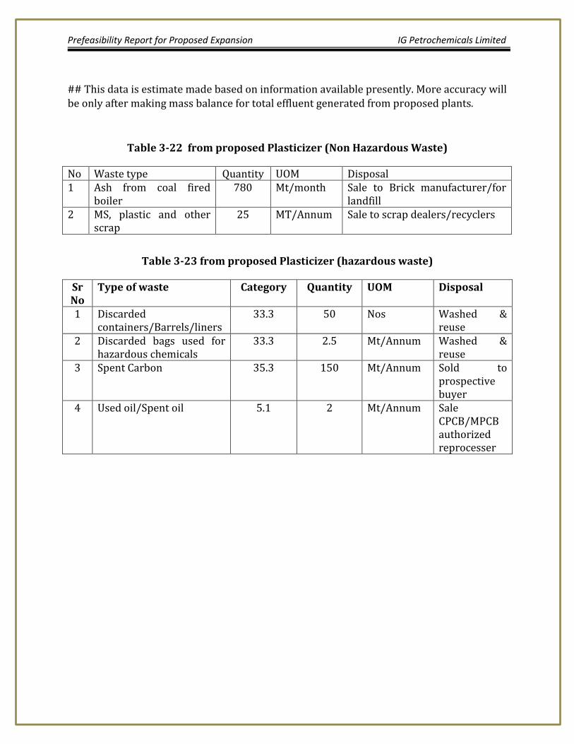
## This data is estimate made based on information available presently. More accuracy will be only after making mass balance for total effluent generated from proposed plants.
Table 3-22 from proposed Plasticizer (Non Hazardous Waste)
No Waste type Quantity UOM Disposal 1 Ash from coal fired
boiler 780 Mt/month Sale to Brick manufacturer/for
landfill 2 MS, plastic and other
scrap 25 MT/Annum Sale to scrap dealers/recyclers
Table 3-23 from proposed Plasticizer (hazardous waste)
Sr No
Type of waste Category Quantity UOM Disposal
1 Discarded containers/Barrels/liners
33.3 50 Nos Washed & reuse
2 Discarded bags used for hazardous chemicals
33.3 2.5 Mt/Annum Washed & reuse
3 Spent Carbon 35.3 150 Mt/Annum Sold to prospective buyer
4 Used oil/Spent oil 5.1 2 Mt/Annum Sale CPCB/MPCB authorized reprocesser
Prefeasibility Report for Proposed Expansion IG Petrochemicals Limited
SITE ANALYSIS 4
Connectivity 4.1
This proposed IG Petrochemicals expansion facility shall be located at its existing Plot T-2 and acquired adjacent plot at MIDC Taloja in Raigad district, Maharashtra.
Land form, Land use and Land ownership 4.2
Land Form: Land is on plain contour, it is flat terrain.
Land Ownership: Land ownership is with project proponents.
Topography 4.3
The project site is located on a relatively level terrain at an average elevation of 15 m above MSL and forms part of catchment area of Kasardi/Kalundri river. Mountain ranges in the area run in the North – South direction. The Malang gadh is located to the North east (having height of 437m) which stretches down south (612m high- 5-6km to the east) and to the South east (medium sized peaks about 400m high, 6-7 km away). There is another
range (Parsik hill) located about 6-7km to the west also running in North-South direction and separating the MIDC Taloja from Navi Mumbai/MIDC, TTC. The area has a coastal climate with monsoon occurring between June to September. Like any other coastal area, wind speed, relative humidity is moderate to high and temperature variation is minimal. Micrometeorological information for IGPL, Taloja was collected by installing a mechanical weather station at project site. Data was collected for wind speed, wind direction, temperature, relative humidity and rainfall. Whereas the first two parameters viz. wind speed and direction play a vital role in dispersion of pollutants the later ones i.e. humidity
and precipitation are important to find amount of deposition for the region.
Wind 4.3.1
The data on wind patterns are pictorially represented by means of wind rose for Winter Jan-Feb 2014 in figure below. The winds were moderate and are predominantly from directions between north and east. Macro level wind patterns seem to be affected by the presence of Arabian sea to the South west and the mountain ranges which deflect the winds. Calm conditions were recorded during the monitoring period. Overall meteorological and topographical condition indicates good dispersion characteristics at
Taloja.
Prefeasibility Report for Proposed Expansion IG Petrochemicals Limited
Figure 4.1 Wind Rose Winter 2014 (Jan-Feb 2014)
Temperature & Humidity 4.3.2
Overall climate of this region is equable with high rainfall in monsoon season and very few days of extreme temperatures. The mean annual temperature ranges from 300C to 330C. The maximum temperature of the hottest month in this area varies from 35oC – 40oC in April-May while minimum temperature of coldest month varies from 15oC to 20oC. Extremes of temperatures, like 46-48oC in summer and 10-120C in winter, may be experienced for a day or two in respective season. The area has humid climate. Relative humidity varies from 25% to 85%. Driest days being in winter and wettest ones
experienced in July.
Rainfall 4.3.3
The monsoon in this region extends from June to September with an average annual rainfall of 2500 – 3000mm.
Existing land use pattern 4.4
The existing land is used for the existing facility is for manufacture of petrochemicals and its byproducts.
Prefeasibility Report for Proposed Expansion IG Petrochemicals Limited
Existing Infrastructure 4.5
Existing Infrastructure: Presently there is an operative plant / well developed
Infrastructure at the site.
4.6 Soil Classification
District Raigad is one of the coastal districts of Konkan region of Maharashtra, spread over an area of 7152 km2. It shows variation in topography from high altitudinal Sahyadri hill ranges to coastal plains. The soils of the district are formed from the predominating rock formation i.e. Deccan Trap. According to the topographical situation and location, soils in
Raigad district are grouped as Forest, Varkas, Rice, Khar or Salt, Coastal Alluvial and Laterite soils. District receives average 3029mm annual rainfall mostly contributed by southwesterly monsoon. These climatic and edaphic conditions support different types of forests.
Prefeasibility Report for Proposed Expansion IG Petrochemicals Limited
pg. 38
PLANNING BRIEF 5
Planning Concept 5.1
Plot is at well-established MIDC Taloja area Purified Water supply from MIDC Road facility with illumination. Infrastructure facilities available established MIDC site Integration with the existing manufacturing facility
5.2 Population Projection
Raigad District is a district in the state of Maharashtra, India. It is located in the Konkan region. The district was renamed after Raigad, the fort that was the former capital of the Maratha leader Shivaji Maharaj, and is located in the interior regions of the district, in dense forests on a west-facing spur of the Western Ghats of Sahyadri range. In 2011 the district had a population of 2,635,394, compared to 2,207,929 in 2001. In 2011 urban dwellers had increased to 36.91% from 24.22% in 2001. The district is bounded by Mumbai Harbour to the northwest, Thane District to the north, Pune District to the east,
Ratnagiri district to the south, and the Arabian Sea to the west. It includes the large natural harbor of Pen-Mandwa, which is immediately south of Mumbai harbour, and forming a single landform with it. The northern part of the district is included in the planned metropolis of Navi Mumbai, and its port, the Jawaharlal Nehru Port. The district includes towns / cities of Panvel Alibag, Mangaon, Roha, Pen, Khopoli, Kharghar, Taloja, Khalapur, Uran, Patalganga, Rasayani, Nagothana, Poladpur, Alibag, Karjat and Mahad. The largest city both in area and population is Panvel. The district also includes the isle of Gharapuri or Elephanta, located in Uran which has ancient Hindu and Buddhist caves. 5.3 Assessment of Infrastructure Demand (Physical and Social):
At IG Petrochemicals Ltd, proposed expansion project there will be increase in production of the chemicals. There will be no major demand of expansion of physical infrastructure and social infrastructure.
Prefeasibility Report for Proposed Expansion IG Petrochemicals Limited
pg. 39
PROPOSED INFRASTRUCT URE 6
Industrial area 6.1
IGPL, MIDC Taloja proposed to increase capacity of synthetic organic chemicals manufacturing facility based on demand and market projection.
Residential Area 6.2
No Residential area has been proposed within the plant site.
Green Belt 6.3
In and around the IGPL plant site, green plantation has been carried out to balance green belt and along the boundary of the plot. For proposed expansion adequate green belt shall be developed.
Social Infrastructure 6.4
The proposed project will generate temporary employment for about 100 persons during the construction phase. The direct employment will be generated during operation phase. Hence, there will be significant positive Impact due to the proposed project. Local people will be given preference wherever found suitable for all the jobs in the plant, direct as well as indirect. Thus the project shall have a positive impact on the employment pattern of the region. Economic status of the local population will improve due to increased ancillary / business opportunities, thereby making positive impact.
Water Management 6.5
The additional water requirement is about 2040 cmd for Domestic, boiler/cooling, greenery and process. The water is available from existing water works of MIDC and the same is adequate and satisfactory. The water supply will be through MIDC from Barvi Dam. IGPL is not encroaching on anybody’s water source.
Sewage System 6.6
IGPL has combined STP/ETP plant for its existing manufacturing operations. It is proposed to expand combined effluent treatment plant to treat additional effluent from
PA4, Plasticizers and neighboring Mysore Petrochemicals limited (sister concern) from MA4 expansion.
Prefeasibility Report for Proposed Expansion IG Petrochemicals Limited
pg. 40
Existing ETP shall be upgraded suitably to treat the above effluent. Brief description of the proposed effluent treatment scheme is given below: In order to treat effluent generated form Proposed plasticizer plants, Phthalic Anhydride plants & Maleic Anhydride plant, existing ETP shall be upgraded suitably or new ETP will be built to treat organic & in organic effluent generated from the proposed plants.
The effluent generated from proposed Plasticizer plant, Maleic Anhydride Plant & Phthalic Anhydride plant will be collected into the oil and alcohol trap for removal of oily layer manually. After removing oily layer, effluent is collected into neutralization tank. NaOH lye or acid will be added in this tank for neutralization. Cooling tower blow down is used for adjusting COD of neutralized effluent before feeding to primary settling tank. In this tank, the sludge will be separated and the sludge from bottom of the settling tank will goes to sludge collection tank for sludge dewatering. From primary settling tank, the overflow goes into aeration tank where the biodegradation will take place in the presence of active biomass and dissolved oxygen in aeration tank will be supplied by adequate capacity of air blower through fine bubble air diffuser. In aeration
tank appropriate quantity of urea and DAP will be added regularly to ensure proper growth of microorganism. The overflow of the aeration tank will be then passed to the secondary clarifier. The overflow the secondary clarifier will be collected into clarified water tank from where it will be pumped to pressure send filter to remove suspended solids, and the outlet of the send filter is passed through activated carbon filter for final polishing of the treated effluent. Clear effluent from the carbon column is diverted into the Treated Water tank. The settled sludge from the secondary settling tank will be recycled back to the aeration tank and excess sludge will be diverted into sludge collection tank for sludge dewatering.
The sludge after dewatering will be packed properly and will be stored in the storage area and the leachate of the sludge storage room and storage area will be collected into the neutralization tank. The treated effluent shall be sent to CETP.
Prefeasibility Report for Proposed Expansion IG Petrochemicals Limited
pg. 41
Solid Waste Management 6.7
Refer above
Power Requirement & Supply/ Source 6.8
Electricity: 2750 Kwh (PA4 & Plasticizer expansion), Source: Captive during normal operation for PA4 and from MSEDCL for plasticizer.
During plant shut down & start up, existing 2000 KVA Diesel generator/ MSEDCL power will be used.
Prefeasibility Report for Proposed Expansion IG Petrochemicals Limited
pg. 42
REHABILITATION AND R ESETTLEMENT 7(R & R PLAN)
The proposed activities are in the existing and acquired neighboring plot of the company
which is located in Taloja MIDC area. It does not require acquisition of Land and the
Infrastructure so there will be no any kind of activity of Rehabilitation and Resettlement
carried out.
Prefeasibility Report for Proposed Expansion IG Petrochemicals Limited
pg. 43
PROJECT SCHEDULE AND COST 8ESTIMATES
Time schedule of the Project 8.1
Since this is an additional production in existing complex of IGPL, hence there is no major
infrastructure requirement for the expansion except relocation of o Xylene Unloading, and
Fire Water reservoir, Coal Fired Boiler etc. in the new plot number T-2 part. After the EC is
granted necessary consent for establishment /operation shall be applied.
Plasticizer project: Likely date of start of construction is Sept 2016 and likely date of
completion is Sept. 2017 PA-4 Project: Likely date of start construction for PA-4 is December 2016 and likely date of completion Dec, 2018.
Estimated project cost (Economic Viability of the Project) 8.2
Overall Project cost is estimated at Rs. 400 Crores
Prefeasibility Report for Proposed Expansion IG Petrochemicals Limited
pg. 44
ANALYSIS OF PROPOSAL (FINAL 9RECOMMENDATIONS)
Financial and Social Benefits 9.1
The global growing demand for phthalic anhydride and its downstream phthalate plasticizers, Maleic anhydride shall give boost to financial economy for the company and to
the nation. It will also benefit the society by way of employment and ancillary industries development.
Prefeasibility Report for Proposed Expansion IG Petrochemicals Limited
Annexure I
pg. 45
Annexure I
IG Petrochemicals site Google Image
Prefeasibility Report for Proposed Expansion IG Petrochemicals Limited
Annexure II
pg. 46
ANNEXURE II
Proposed Layout Plan
Prefeasibility Report for Proposed Expansion IG Petrochemicals Limited