Pre-Feasibility Report Proposed Expansion & Change in Product Mix by way of Debottlenecking & Modernization at Patalganga Manufacturing Division Prepared for PATALGANGA MIDC, MAHARASHTRA July 2018
Transcript
Pre-Feasibility Report
Proposed Expansion & Change in Product Mix by way of
Debottlenecking & Modernization
at Patalganga Manufacturing Division
Prepared for
PATALGANGA MIDC, MAHARASHTRA
July 2018
Reliance Industries Limited – PMD Page 2
CONTENTS
1. Executive Summary
2. Introduction
3. Site Analysis
4. Project Description
5. Project Implementation
6. Regional Setting
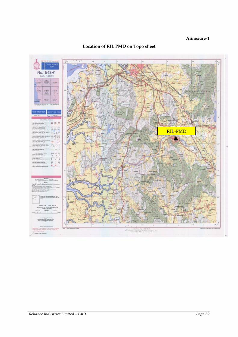
a. Annexure 1: Project location on Toposheet
b. Annexure 2: Overall Plot plan of PMD
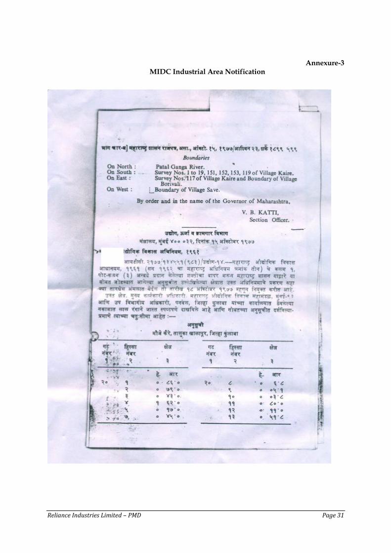
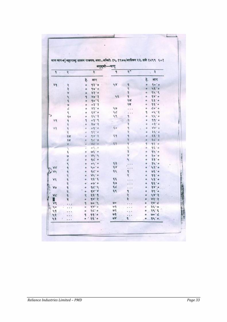
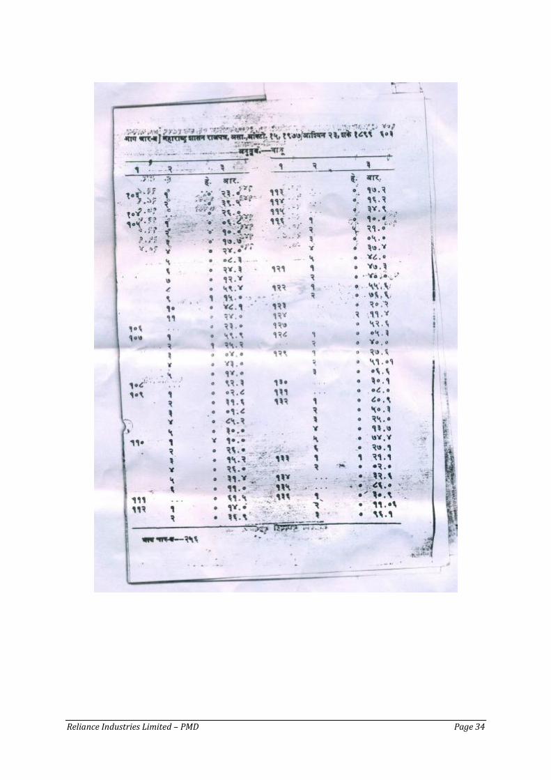
c. Annexure 3: MIDC Industrial Area Notification
d. Annexure 4: Effluent Treatment Plant Schematic
Reliance Industries Limited – PMD Page 3
1. EXECUTIVE SUMMARY
Patalganga Manufacturing Division (PMD) of Reliance industries Limited (RIL) is located at
Patalganga MIDC, Village Kaire, Tehsil Khalapur, District Raigad, Maharashtra. With the
availabity of feedstock from nearby petroleum refineries in Mumbai, RIL set-up
Petrochemicals Manufacturing Division in the year 1985 with valid consents from
Maharashtra Pollution Control Board (MPCB) for its manufacturing divisions namely Linear
Now, RIL PMD intends expansion & change in product mix by way of debottlenecking &
modernization of its PTA, LAB & CPP units. The existing PMD is spread over ~65.6 hectares
and proposed project will come up within this area and no additional land is required
The PTA unit presently produces Para-Xylene (PX) & Purified Terephthalic Acid (PTA) and its associated by-products. Now, the PTA unit is planning a project for change in its product mix. In the proposed project, it is planned to produce either Pure Isophthalic Acid (PIA), Meta-xylene (MX) & Reformate or Para-Xylene (PX) & Purified Terephthalic Acid (PTA) and its associated by-product on need and market demand. In this project a flexibility will be created within the existing PTA units to either product PX along with PTA or MX along with PIA and Reformate. This project activity is only a creating flexibility to change in the existing product mix. The LAB unit presently produces LAB along with its by-products by using HF as a catalyst. Now, it is planned to modernize the existing unit by replacing the HF catalysts with an Ionic Liquid based catalyst process developed in-house or UOP based Detal process using a solid acid catalyst & debottleneck the units to increase the production capacity. The gas based Captive Power Plant presently has 48 MW (2 x 24) which will be refurbished to 66 MW (2 x 33) with an addition of 24 MW STG to utilize the excess steam which will be generated from the uprate of GTs.
There is negligible change in the water requirement & effluent generation due to this project activity. The exact quantity and quality of the wastewater shall be quantified and characterized during the detailed engineering stage and the same shall be considered in the environment impact study for the proposed project.
The expected air emissions from petrochemical manufacturing units are PM, SO2, NO2 and hydrocarbons (HCs/VOCs). In PMD natural gas is used as the major fuel along with Naphtha, LSHS, FO, HSD/ Kerosene as standby for combustion. Hence, emission are negligible, adequate measures are taken in place to control such emissions.
Existing manpower would suffice as the project. The proposed project will be carried out at a capex of Rs. 875 Crs.
Reliance Industries Limited – PMD Page 4
2. INTRODUCTION
Reliance Industries Ltd. (RIL) is a pioneer in the petrochemical sector and is dedicated to
bring our country to an enviable status in the world. RIL is organized in 3 major business
segments namely (i) Exploration and Production of Oil and Gas, (ii) Refining/ Marketing of
petroleum products and (iii) Manufacturing and Marketing of Petrochemicals, Polymers,
Polyesters, Polyester intermediates. RIL has major production facilities located in Jamnagar,
Dahej, Hazira, Baroda, and Naroda in Gujarat State; Nagothane, and Patalganga in
Maharashtra and Silvassa in UT of Dadra & Nagar Haveli; and Kakinada in Andhra
Pradesh.
With the availabity of feedstock from nearby petroleum refineries in Mumbai, RIL set-up
Petrochemicals Manufacturing Division (PMD) at Patalganga in the year 1985 with valid
consents from Maharashtra Pollution Control Board (MPCB) for its manufacturing divisions
These manufacturing divisions are located within the declared industrial area at Patalganga
MIDC notified by Maharashtra Industrial Development Corporation (MIDC), Govt. of
Maharashtra, at Village Kaire, Tehsil Khalapur, District Raigad, Maharashtra.
RIL-PMD intends to bring in a change in the product mix the Purified Terephthalic Acid (PTA) unit, debottleneck & modernize the existing Linear Alkyl Benzene (LAB) unit and expand the 48 MW CCPP to 90 MW.
Change in Product mix at PTA
The PTA unit presently produces Para-Xylene (PX) & Purified Terephthalic Acid (PTA) and its associated by-products. Now, the PTA unit is planning a project for change in its product mix. In the proposed project, it is planned to produce either Pure Isophthalic Acid (PIA), Meta-xylene (MX) & Reformate or Para-Xylene (PX) & Purified Terephthalic Acid (PTA) and its associated by-product on need and market demand. In this project a flexibility will be created within the existing PTA units to either product PX along with PTA or MX along with PIA and Reformate. This project activity is only a creating flexibility to change in the existing product mix.
Debottlenecking & Modernization at LAB & CPP
The LAB unit presently produces LAB along with its by-products by using HF as a catalyst. Now, it is planned to modernize the existing unit by replacing the HF catalysts with an Ionic Liquid based catalyst & debottleneck the units to increase the production capacity. The gas based Captive Power Plant presently has 48 MW (2 x 24) which will be refurbished to 66 MW (2 x 33) with an addition of 24 STG to utilize the excess steam which will be generated from the GTs.
Reliance Industries Limited – PMD Page 5
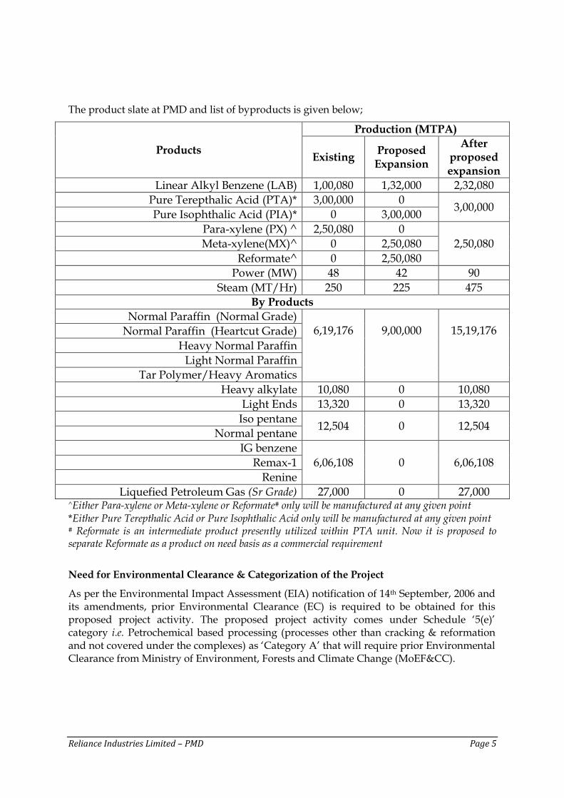
The product slate at PMD and list of byproducts is given below;
Products
Production (MTPA)
Existing Proposed Expansion
After proposed expansion
Linear Alkyl Benzene (LAB) 1,00,080 1,32,000 2,32,080
Pure Terepthalic Acid (PTA)* 3,00,000 0 3,00,000
Pure Isophthalic Acid (PIA)* 0 3,00,000
Para-xylene (PX) ^ 2,50,080 0
2,50,080 Meta-xylene(MX)^ 0 2,50,080
Reformate^ 0 2,50,080
Power (MW) 48 42 90
Steam (MT/Hr) 250 225 475 By Products
Normal Paraffin (Normal Grade) 6,19,176
9,00,000
15,19,176 Normal Paraffin (Heartcut Grade)
Heavy Normal Paraffin
Light Normal Paraffin
Tar Polymer/Heavy Aromatics
Heavy alkylate 10,080 0 10,080
Light Ends 13,320 0 13,320
Iso pentane 12,504 0 12,504
Normal pentane
IG benzene
6,06,108 0 6,06,108 Remax-1
Renine
Liquefied Petroleum Gas (Sr Grade) 27,000 0 27,000 ^Either Para-xylene or Meta-xylene or Reformate# only will be manufactured at any given point *Either Pure Terepthalic Acid or Pure Isophthalic Acid only will be manufactured at any given point # Reformate is an intermediate product presently utilized within PTA unit. Now it is proposed to separate Reformate as a product on need basis as a commercial requirement
Need for Environmental Clearance & Categorization of the Project
As per the Environmental Impact Assessment (EIA) notification of 14th September, 2006 and its amendments, prior Environmental Clearance (EC) is required to be obtained for this proposed project activity. The proposed project activity comes under Schedule ‘5(e)’ category i.e. Petrochemical based processing (processes other than cracking & reformation and not covered under the complexes) as ‘Category A’ that will require prior Environmental Clearance from Ministry of Environment, Forests and Climate Change (MoEF&CC).
Reliance Industries Limited – PMD Page 6
3. SITE ANALYSIS
Location / Project Siting
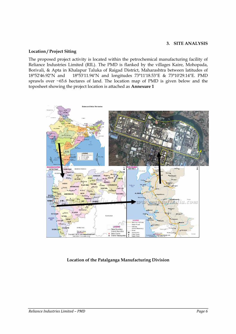
The proposed project activity is located within the petrochemical manufacturing facility of Reliance Industries Limited (RIL). The PMD is flanked by the villages Kaire, Mohopada, Borivali, & Apta in Khalapur Taluka of Raigad District, Maharashtra between latitudes of 18°52'46.92"N and 18°53'11.94"N and longitudes 73°11'18.53"E & 73°10'29.14"E. PMD sprawls over ~65.6 hectares of land. The location map of PMD is given below and the toposheet showing the project location is attached as Annexure 1
Location of the Patalganga Manufacturing Division
Reliance Industries Limited – PMD Page 7
Connectivity
RIL PMD is located within MIDC notified Industrial area and is well connected by rail and road network. Nearest railway station Apta which is at an aerial distance of ~ 3.6 km. in south west direction and Mumbai-Pune National Highway (NH-4) is ~2 km aerial distance North-East direction. The nearest airport is Mumbai which is located at an aerial distance of ~40 km in North-west direction. Climatic Conditions
Overall climate is equable with average rainfall of 3884 mm per year and very few days of extreme temperatures. The mean annual temperature ranges from 30oC to 33oC. The mean maximum temperature of the summer month in this region varies from 30oC-40oC while mean minimum temperature of winter month varies from 15oC to 20oC. The area has humid climate. Relative humidity varies from 25% to 85%. Driest days being in winter and wettest ones are experienced in July. The rainy season is mostly confined to southwest monsoon.
Reliance Industries Limited – PMD Page 8
3. PROJECT DESCRIPTION
Project Information
RIL PMD proposes a change in the product mix of the existing PTA unit and capacity enhancement of LAB & CPP by and expansion of existing plant & infrastructure. PTA project activity provides flexibility of utilizing the existing units of PTA to produce Meta-xylene (MX), Reformate & Pure Isophthalic Acid (PIA) i.e. we can either produce Para-Xylene (PX) along with PTA or Meta-Xylene (MX) along with PIA and Reformate. In the LAB unit it is planned to modernize the existing unit by replacing the HF catalysts with an Ionic Liquid based catalyst & debottleneck the units to increase the production capacity. The 48 MW gas based Captive Power Plant presently will be expanded to 90 MW by refurbishing the existing GTs along with an addition of 24 STG to utilize the excess steam which will be generated from the GTs. All these above mentioned activity will be carried out within the existing PMD facility which is spread over ~65.6 ha and no additional land is required.
Project Justification
The need for petrochemical products and the following important features, justifies the project to be undertaken by PMD facility. The following features also justify, infrastructure, connectivity, facilities for export/import and market potential.
Create flexibility in the existing available units and extract additional value added products based on requirement
Replacing hazardous HF catalyst-based process with ionic liquid catalyst-based process developed in-house
PMD is located within MIDC notified Industrial area
Availability of requisite infrastructure facilities;
No additional land required;
Lower capital cost compared to the grass root project. This would save the capital cost resulting in lower cost or production and retention price;
Optimization of power and utilities assets;
Meeting the gap in demand and supply of petrochemicals in the country;
Due to the optimization and use of available infrastructure and associated utilities for the proposed project activity, the environmental impacts will be reduced.
RIL PMD has a well-established Environmental Management System, which will be strengthened and will cover this proposed project as well.
The existing ETP will be used to treat the effluent from the proposed project activity also
RIL facility is a member of the nearest TSDF located at Taloja, which will be extended to the proposed project activity also
Project Area
The PMD is located within the MIDC allocated area of around 65.6 hectare. The proposed project shall be within the allocated land of MIDC. The MIDC industrial area notification is attached as Annexure-3. Other areas includes land requirement of roads, drains/ trenches, parking, transmission corridor, are already available in the existing process plants. The overall PMD layout is enclosed as Annexure – 2
Reliance Industries Limited – PMD Page 9
Land Break-Up
Facilities Area (in hectares)
i. Process Plants, Utilities, Captive power plant, Tank farm and Storage facilities
59
ii. Open areas, Roads, Approaches and Safe distances,
0.3
iii. Greenbelt/landscaping 6.3
Total 65.6
Employment Generation due to the project
The existing manpower at plant is ~1000 (450 RIL & 550 contract labour). Existing manpower would suffice as the project is only a change in product mix at PTA and modernization & debottlenecking of LAB & CPP.
Project Cost
Since the proposed activities will be carried out within the existing plant. Hence, no additional land is required for the proposed project. The proposed project will be carried out at a capex of Rs. 875 Crs. Environment Protection and safety systems have also been considered in planning the cost projection.
Reliance Industries Limited – PMD Page 10
4. PROCESS DESCRIPTION
The raw materials for the PTA/PIA manufacturing is heavy Naphtha/ Reformate & Kerosene. These raw materials are are pumped from BPCL/ HPCL Refinery at Chembur a through dedicated pipeline of ~ 52 km distance and Reformate is produced in-house or obtained from RIL- Jamnagar on need basis.
Pure Terepthalic Acid (PTA)
PTA division consists of Xylene unit where the feedstock Naphtha is used to produce Para-Xylene (PX) or Meta-Xylene (MX) or Reformate. PX or MX are intermediate products to produce either PTA or Pure Isophthalic Acid (PIA) as required. The following section describes in the brief the process and the proposed modifications.
Xylene Unit
In the xylene unit, PX or MX is produced and the process is divided into the following major sections;
A brief description of the above process in given below;
Naphtha Pre-fractionation Section: Feedstock to the process is a narrow cut Naphtha of 120 - 150 Deg C boiling range from refineries. Since refinery is supplying straight run naphtha of boiling range 90-180 Deg C, this Naphtha is fractionated in Prefractionation unit for the narrow cut for removal of Light Naphtha, Heavy Naphtha and get desired Heart cut Naphtha.
Naphtha Hydro-treating Section: The Naphtha Hydro-treating process is a catalytic reforming process employing a select catalyst and Hydrogen rich gas stream to decompose organic sulphur, oxygen and nitrogen compounds contained in hydrocarbon fractions. In addition hydro-treating removes organo-metallic compounds and saturated olefinic compounds. Hydro-treating processing is commonly used to remove platforming catalyst poisons/impurities from heart cut Naphtha prior to charging to the platforming process unit.
CCR Platforming Section: The unit converts Naphtha to Aromatics Rich Feedstock. It consists of two sections
o Moving Bed Reaction Section
o Continuous Catalyst Regenerator
Major reactions taking place in the Reactor are as follows;
Reliance Industries Limited – PMD Page 11
Dehydrogenation of Naphthenes to aromatics-endothermic, promoted by metal function of catalyst favored by high reaction temp. and low pressure
Hydrocracking of paraffins-consumes hydrogen, exothermic, severe hydrocracking reduces liquid yield
Isomerization: Mildly exothermic, products subject to further reaction to form aromatics or smaller paraffins.
Dehydrocyclisation of paraffins to naphthenes: This reaction will precede the dehydrogenation of naphthene to aromatics
Major products of Platforming Section are Aromatics Rich Feedstock, Hydrogen, Fuel Gas and LPG.
During Normal Operation, Catalyst get deactivated due to coke formation on the catalyst. The Continuous Catalyst Regenerator (CCR) allows to remove small quantity of Catalyst from Reactor bottoms and Catalyst activity is regained by burning of coke in CCR. The regenerated catalyst is sent back to Reactor Section.
Reformate produced in Platforming unit is fractionated in Platforming Deheptaniser Column to produce C7- Aromatics Stream and C8+ Aromatics Stream. The C7-Aromatics Stream is sent for Pentane Recovery Unit and C8+Aromatics Stream is sent to Xylene Faction Section.
Xylene Fractionation Section: This unit consist of two distillation columns. The function of the unit to prepare feed stocks for MX SORBEX or PAREX Section as per need and Tatoray units. The C8+ Aromatics Stream generated in Platforming Unit is fed to this section via clay Treaters. The main function of this section is to separate C8 Aromatics and sent for MX/PX Recovery or Reformate. Heavies (C9+Aromatics Stream is further fractionated in THFR Column to separate C9A for use in Tatoray Unit
MX SORBEX Section: The UOP MX SORBEX process is a well-established, commercially proven adsorptive separation method for the recovery of high purity Meta-Xylene from C8 Aromatic fractions obtained from the overhead of xylene rerun column. This uses a solid adsorbent, a zeolitic material, a liquid Desorbent, toluene and a flow directing device called, the “Coplanar Manifolding Indexer” or CMI. Selective adsorption of meta-Xylene is effected according to the UOP Sorbex Simulated Moving Bed Technology to produce MX with a purity of 99.5 wt-% and per pass recovery of 97%. This unit generate C8 Aromatics Stream (Raffinate) which is lean in MX and sent to Isomar Section.
The same unit will be used for recovery of Para-Xylene (PX) from C8 aromatic fractions using a selective adsorbent and paradiethyl benzene as a liquid desorbent. Subsequently, the raffinate stream which is lean in PX is sent to the isomar section.
Isomar Section: Isomar is a catalyst isomerization process to efficiently convert mixture of C8 aromatics to a near equilibrium mixture. The other Xylenes PX and OX are converted to MX and Ethyl benzene is converted to Benzene. Reactor product is fractionated in Iso Deheptaniser column to separate into C8+Aromatics Stream and Light ends The C8+Aromatics stream is sent back to Xylene Fractionation Section and Light ends are sent to LPG, Pentane and Benzene Recovery.
Reliance Industries Limited – PMD Page 12
Tatoray Section: The Tatoray is a catalytic process where Toluene and C9 Aromatics are converted to C8 Aromatics and Benzene via Transalkylation. Reactor product is fractionated to get C8+ Stream which is sent back to Xylene fractionation Section and Benzene and LPG are recovered in respective Section.
LPG Recovery Section and Pentane Recovery Section: These are byproducts recovery section where LPG and Pentanes generated in Platforming Section, Isomar Section and Tatoray Section are recovered
Odourization of the LPG: As standard practice, all LPG shall be odorized prior to delivery to bulk plant by addition of a warning agent of such character that the gases are detectable, by distinct odor to a concentration in air of not over one fifth the lower limit of flammability
Reformate Production: Reformate can be characterized as a feed rich in C8 Aromatics which can be used for PX production or can be extracted as a product during MX production.
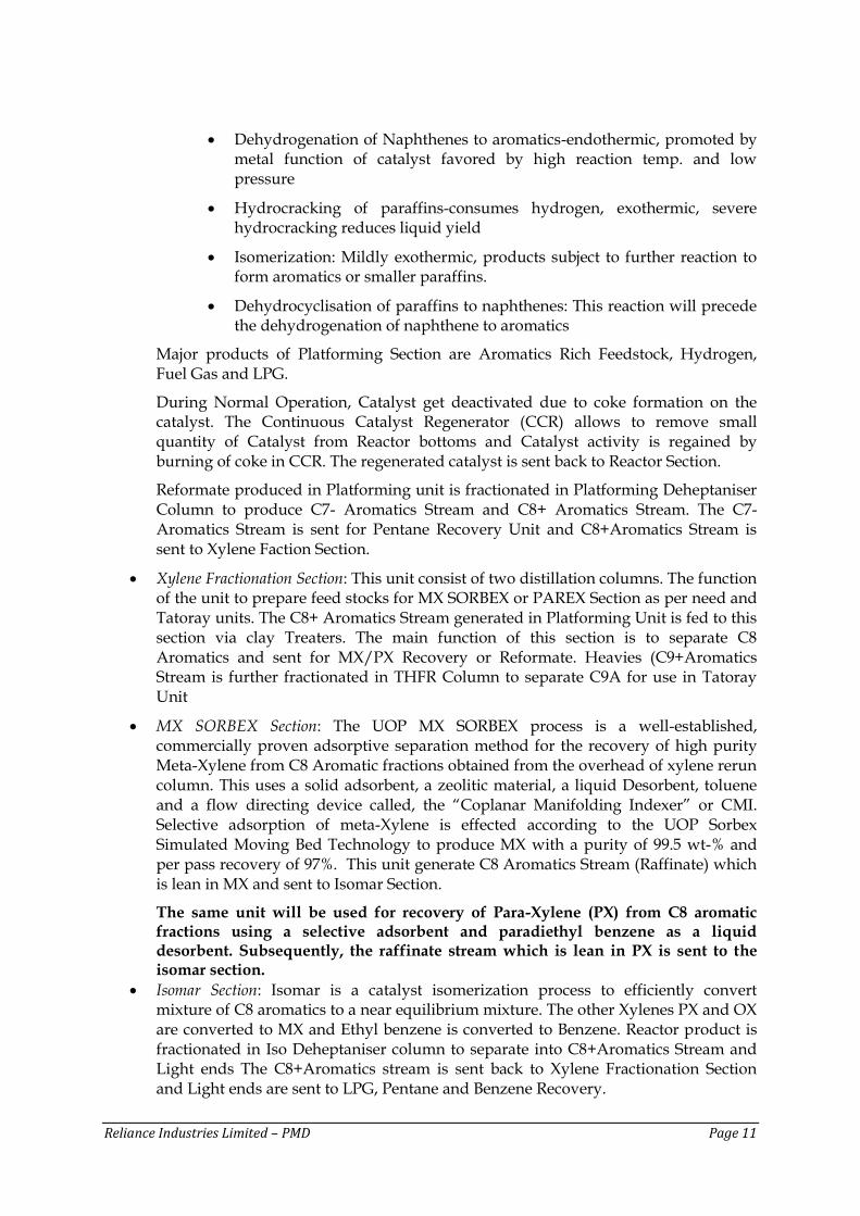
Process schematic
Proposed Modification
In the UOP SORBEX section, change of adsorbent to either produce PX or MX
As per the requirement, the adsorbent will be changed as mentioned above in the SORBEX section and accordingly, the PTA or PIA will be produced. To produce either PTA or PIA from PX or MX, the process undergoes the following 2 stages;
Oxidation Section
Purification Section
MX PX
Reliance Industries Limited – PMD Page 13
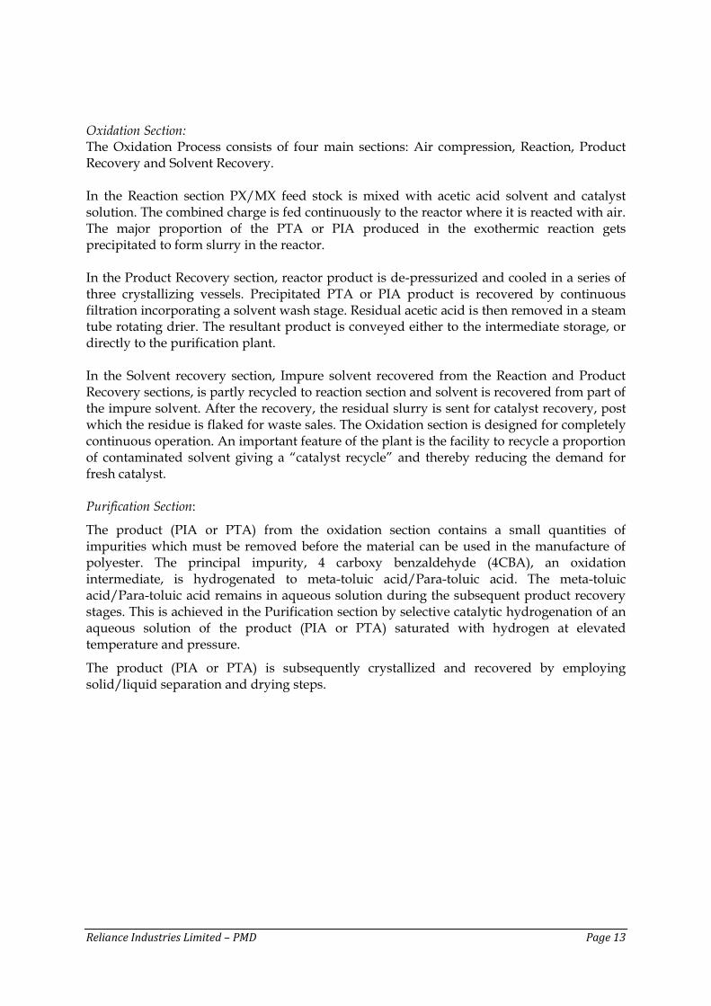
Oxidation Section: The Oxidation Process consists of four main sections: Air compression, Reaction, Product Recovery and Solvent Recovery.
In the Reaction section PX/MX feed stock is mixed with acetic acid solvent and catalyst solution. The combined charge is fed continuously to the reactor where it is reacted with air. The major proportion of the PTA or PIA produced in the exothermic reaction gets precipitated to form slurry in the reactor.
In the Product Recovery section, reactor product is de-pressurized and cooled in a series of three crystallizing vessels. Precipitated PTA or PIA product is recovered by continuous filtration incorporating a solvent wash stage. Residual acetic acid is then removed in a steam tube rotating drier. The resultant product is conveyed either to the intermediate storage, or directly to the purification plant.
In the Solvent recovery section, Impure solvent recovered from the Reaction and Product Recovery sections, is partly recycled to reaction section and solvent is recovered from part of the impure solvent. After the recovery, the residual slurry is sent for catalyst recovery, post which the residue is flaked for waste sales. The Oxidation section is designed for completely continuous operation. An important feature of the plant is the facility to recycle a proportion of contaminated solvent giving a “catalyst recycle” and thereby reducing the demand for fresh catalyst. Purification Section:
The product (PIA or PTA) from the oxidation section contains a small quantities of impurities which must be removed before the material can be used in the manufacture of polyester. The principal impurity, 4 carboxy benzaldehyde (4CBA), an oxidation intermediate, is hydrogenated to meta-toluic acid/Para-toluic acid. The meta-toluic acid/Para-toluic acid remains in aqueous solution during the subsequent product recovery stages. This is achieved in the Purification section by selective catalytic hydrogenation of an aqueous solution of the product (PIA or PTA) saturated with hydrogen at elevated temperature and pressure.
The product (PIA or PTA) is subsequently crystallized and recovered by employing solid/liquid separation and drying steps.
Reliance Industries Limited – PMD Page 14
Process schematic
PTA Process Oxidation (Block Diagram)
Oxidation Reaction
Feed Preparation (PX + AA + Catalyst)
Crystallization
Vacuum Filtration
Drying
Crude TA to intermediate storage
Compressed Air
PTA Process Purification (Block Diagram)
Purification Reaction
Feed Preparation & Preheating
Crystallization
Centrifuging
Drying
PTA to product silos
Hydrogen
Proposed Modification as a part of this project:
The following modifications are being proposed;
Reduction of operating pressures in both oxidation and purification section
Installation of catalyst recovery unit
Installation of purification mother liquor flash cooling for improved solids recovery
Installation of Regenerative Thermal Oxidiser (RTO) for reactor off-gas treatment
PTA/PIA by PX/MX Oxidation
PX/MX, Catalyst
and Solvent
Crude Terephthalic or Isophthalic acid to intermediate storage
PTA/ PIA to Product Storage
Reliance Industries Limited – PMD Page 15
Replacing conventional two stage product separation with single stage rotary
pressure filter
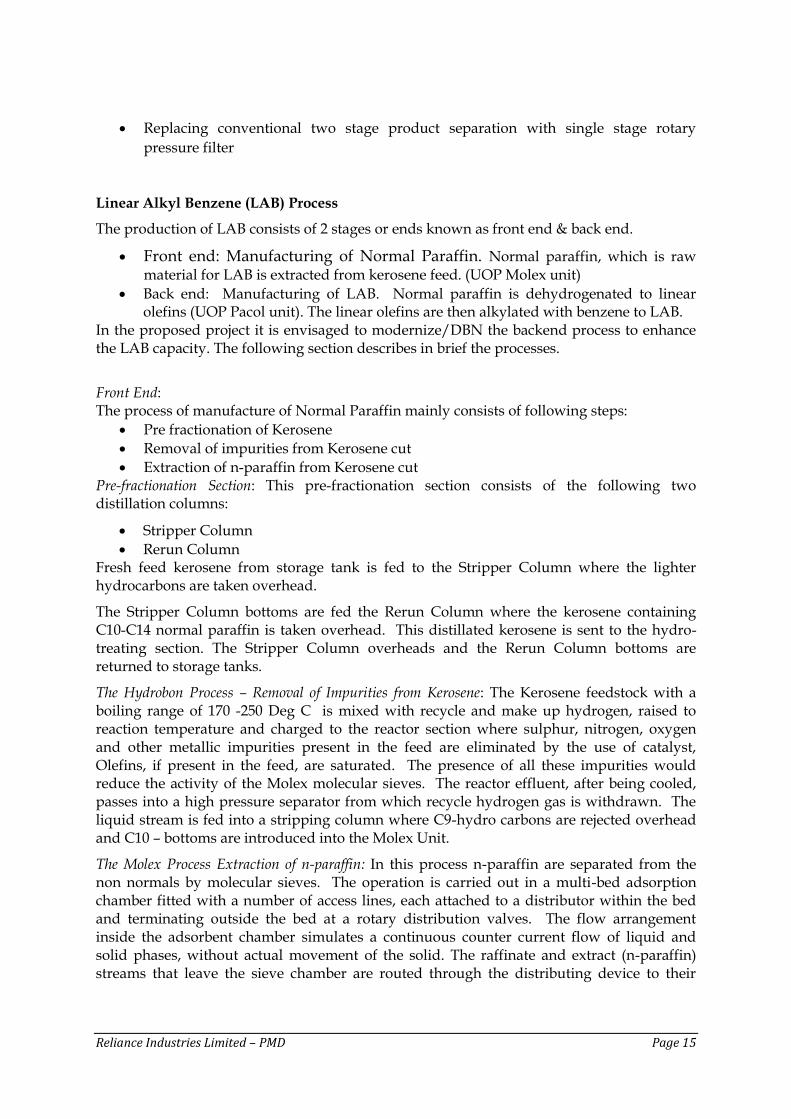
Linear Alkyl Benzene (LAB) Process
The production of LAB consists of 2 stages or ends known as front end & back end.
Front end: Manufacturing of Normal Paraffin. Normal paraffin, which is raw material for LAB is extracted from kerosene feed. (UOP Molex unit)
Back end: Manufacturing of LAB. Normal paraffin is dehydrogenated to linear olefins (UOP Pacol unit). The linear olefins are then alkylated with benzene to LAB.
In the proposed project it is envisaged to modernize/DBN the backend process to enhance the LAB capacity. The following section describes in brief the processes.
Front End: The process of manufacture of Normal Paraffin mainly consists of following steps:
Pre fractionation of Kerosene
Removal of impurities from Kerosene cut
Extraction of n-paraffin from Kerosene cut Pre-fractionation Section: This pre-fractionation section consists of the following two distillation columns:
Stripper Column
Rerun Column Fresh feed kerosene from storage tank is fed to the Stripper Column where the lighter hydrocarbons are taken overhead.
The Stripper Column bottoms are fed the Rerun Column where the kerosene containing C10-C14 normal paraffin is taken overhead. This distillated kerosene is sent to the hydro-treating section. The Stripper Column overheads and the Rerun Column bottoms are returned to storage tanks.
The Hydrobon Process – Removal of Impurities from Kerosene: The Kerosene feedstock with a boiling range of 170 -250 Deg C is mixed with recycle and make up hydrogen, raised to reaction temperature and charged to the reactor section where sulphur, nitrogen, oxygen and other metallic impurities present in the feed are eliminated by the use of catalyst, Olefins, if present in the feed, are saturated. The presence of all these impurities would reduce the activity of the Molex molecular sieves. The reactor effluent, after being cooled, passes into a high pressure separator from which recycle hydrogen gas is withdrawn. The liquid stream is fed into a stripping column where C9-hydro carbons are rejected overhead and C10 – bottoms are introduced into the Molex Unit.
The Molex Process Extraction of n-paraffin: In this process n-paraffin are separated from the non normals by molecular sieves. The operation is carried out in a multi-bed adsorption chamber fitted with a number of access lines, each attached to a distributor within the bed and terminating outside the bed at a rotary distribution valves. The flow arrangement inside the adsorbent chamber simulates a continuous counter current flow of liquid and solid phases, without actual movement of the solid. The raffinate and extract (n-paraffin) streams that leave the sieve chamber are routed through the distributing device to their
Reliance Industries Limited – PMD Page 16
respective fractionation columns where the desorbent, raffinate and extract stream are separated
Back End:
Normal Paraffin Pre fractionation Unit: The N-paraffin stream from the Molex Units further pre-fractionated to obtain the heart cut paraffin prior to feeding the Pacol Unit. This section comprises a Stripper and a Rerun Column for removal of lighters (Stripper overhead) and heaviers (Rerun Bottoms). The Rerun overhead (heart-cut) is then fed to the Pacol Unit.
The Pacol Process Dehydrogenation of n-paraffin: The fresh and (recycle the detergent alkylation unit) nC10 to nC13 paraffin are charged to the Pacol reaction section along with recycle hydrogen. The reactor effluent is charged to a low pressure separator from which recycles plus a small quantity of net hydrogen is withdrawn. The liquid phase from the separator is fed to a stripping column. This column serves to remove traces of dissolved gases and cracked products from the alkylation unit feed.
Detergent Alkylation Process: The mixture of C10-C13 n-paraffin, olefins and fresh benzene are combined with recycle benzene and fed to a two stage reactor section. The streams of benzene (both fresh and recycle) and catalyst (ionic liquid patented by RIL) is mixed in a static mixer before being passed through the two stage reaction mixer. The reactor effluent passes to separating drums where the catalyst settle out and is sent to the trans-alkylation reactor. The hydrocarbon layer is sent to a column for separation of chlorides and benzene. Benzene recovered is then passed through an alumina treater and the purified benzene is sent as recycle. HCl vapors from column pass through a scrubber package. The bottoms of this column then passes through another alumina treater before being feed to benzene column and downstream sections for separation of Benzene, Paraffin, LAB and HAB. The spent catalyst stream sent to Trans-alkylation reactor is used to convert a stream of HAB and benzene in a CSTR. The outlet of the trans-alkylation reactor is sent to a settler where separation of hydrocarbon and catalyst phases takes place. The hydrocarbons are fed to a similar HCl benzene separation column and separated benzene after being fed through alumina treater is recycled back. The column bottom is sent to light ends column for separation of lighters from LAB, HAB. The column bottom is sent to another column for separation of LAB and HAB. There is separate package unit for manufacture of catalyst and recovery of Tar polymers from the spent catalyst.
The overhead paraffin are recycled to the dehydrogenation unit. The bottoms flow to the Rerun & Recovery columns, in which the finished LAB is taken as an overhead cut and heavy alkylate is taken at bottom.
Reliance Industries Limited – PMD Page 17
Process schematic
DBN units
Proposed Modification: In the proposed capacity enhancement proposal of LAB the following modifications are planned.
Replacing hazardous HF catalyst-based process with one of the following non-hazardous alkylation process a. Ionic liquid catalyst-based process developed in-house b. UOP based Detal process using a solid acid catalyst.
Replacing existing mixer-settler based reactor with new reactor system
Installing Trans alkylation process to convert low value by-product to LAB
Certain equipment’s will be replaced/modified such as Distillation column, Alumina Treater, Agitated reactor, Vessels, Mixers, Rotary pressure filter package, Vacuum drier package, Exchangers, Pumps, Air cooled exchangers etc.,
Details of the Process will be provided in the EIA report Utilities
The PMD petrochemical manufacturing facility plant has an integrated utilities system which includes plants for the treatment and distribution of raw water steam/condensate, cooling water, DM water, fire water, compressed air, nitrogen and oxygen, hydrogen, fuel gas and power plant. Whereas offsite facilities includes the storage, receipts & transfer, loading and unloading of chemicals, products and by-products. The areas covered under utilities are listed below, the proposed project shall utilize the existing utilities during its operations and expansion is proposed only in the CPP through DBN.
Air Separation Unit
Compressed air system
Reliance Industries Limited – PMD Page 18
DM water plant
Raw water
Cooling towers
Captive Power Plant
Fire water system
Tank farm
Effluent Treatment Plant (ETP)
Captive Power Plant (CPP)
The power requirement for the existing plants at PMD is met through a captive power plant of capacity 48 MW (2 x 24). Fuel is fired in Gas turbine (GT) combustors where heat of the fuel is consumed. GT generates power and unutilized heat is sent out in the form of exhaust flue gases to the Heat Recovery Steam Generator (HRSG). The GT exhaust is used in HRSG to recover heat and steam. Proposed Modification
In the proposed project, it is envisaged to increase the capacity of each GT from existing 24 MW to 33 MW by passing the inlet air through an inlet air chilling system which reduces the temperature of the inlet air by 16°C from the ambient temperature and by replacing some of the parts of the Gas Turbines and changing the control system software it is possible to increase the capacity of the Gas turbines from 24 MW each to 33 MW and other refurbishment measures. This will enable the increase in power generation through existing GT’s from 48 MW to 66 MW. A STG of 24 MW capacity is proposed to be installed to generate power by utilizing the surplus steam which is generated from HRSG. Therefore, post the proposed project, the total installed & operating capacity of the CPP will be 90 MW.
Power Evacuation
Power generated, from the CPP, is evacuated through HT cables on the pipe rack. Also the system will be connected through suitable step up transformer to the existing 100KV system or 220KV system as per the grid requirement. Power also be evacuated to other Reliance Facilities located elsewhere through State and Interstate grid network. Environmental Aspects
This proposed project is change in product mix by utilizing the existing PTA units & modernization & debottleneck of the Linear Alkyl Benzene (LAB) & CPP units. It shall not have any significant adverse impact on the environment setting of the region. The details on the existing pollution load and after the proposed project will be provided in the EIA report. However, this section provides the brief on the environment considerations of the proposed project.
Reliance Industries Limited – PMD Page 19
Air Emissions
The expected air emissions from a petrochemical manufacturing units are PM, SO2, NO2 and hydrocarbons (HCs/VOCs). At PMD, natural gas is used as the major fuel along with Naphtha, LSHS, FO, HSD/ Kerosene as standby for combustion. Hence, emission of SO2 will be negligible due to burning of fuel. NOx will be generated from the furnaces. Such emissions will be controlled and will be within stipulated standards. However, adequate measures shall be place to mitigating impacts on ambient air quality during the project operations. PM emission is envisaged from the process plants. Although, PM emission are very negligible, adequate measures such as bag filters are in place to control such emissions. Fugitive emissions in the form of VOCs is envisaged. To control such emissions, adequate measures are in place such as provision of internal floating roof tanks with flexible double seal for storage tanks, mechanical seals in pumps etc. In the LAB units 2 heaters will be modified and accordingly the existing stacks will be modified.
Noise The major source of noise generation shall be from process plants, compressors, pumps, etc. In the proposed project there is no anticipated increase in noise level. However, adequate precaution will be in place to maintain noise level within prescribed limits.
Water Consumption and Effluent Generation
PMD has water allocation of 18960 m3/day from MIDC and also consented by MPCB. This allocated quantity of water from MIDC will suffice the requirement of the proposed project too. The water requirement for the proposed project is for operation of its processes, process cooling, utilities cooling, domestic consumption, fire water make up and greenbelt development etc. No adverse environmental impact is envisaged due to withdrawal of water by proposed project. The existing water requirements at PMD is 13,098 m3/d. after the proposed project the water requirement is expected to be 18,960 m3/d i.e within the permitted water allocation to PMD.
The existing effluent from PMD facility is ~5768 m3/d & after the proposed expansion the effluent generation is expected to be ~6018 m3/d. During the proposed project an RO is proposed to be installed to reduce the net raw water requirement by way of recycle/reuse of treated wastewater to the maximum possible extent wherever it is feasible. The treated effluent will be sent to CETP of patalganga MIDC.
The exact quantity and quality of the wastewater shall be quantified and characterized during the detailed engineering stage and the same shall be considered in the environment impact study for the proposed project.
Reliance Industries Limited – PMD Page 20
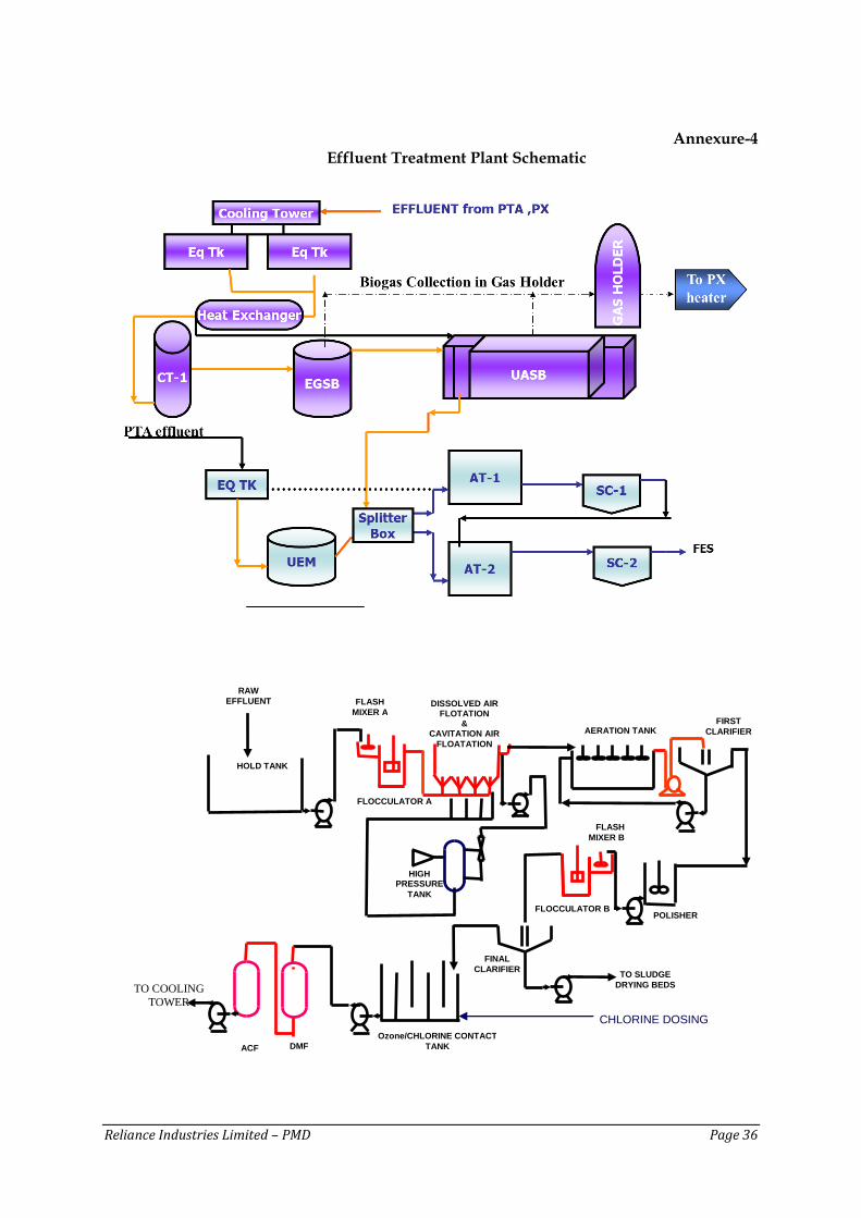
Effluent Treatment Plant (ETP) A brief on the ETP is given below; PMD facility consists of ETPs to treat effluent from PTA & LAB. The treated effluent from LAB is recycled back to Cooling towers. The treated effluent from PTA is sent to CETP of MIDC. The following section describes in brief the ETP of PTA. The treatment consists of the following stages of operations:
Equalization
Anaerobic Treatment
Aerobic treatment Equalization: The effluent flow can vary in terms of both quality and quantity. To ensure that treatment system operates at fairly steady condition, an equalization tank has been provided to balance the flows from various sections of the plants in the PTA Division. The equalization tanks are provided with an array of aeration grids and a common blower. Air is blown through these to keep the tank contents in a homogeneous state. After homogenization in the first compartment, the mixed effluent flows in the next compartment where it is mixed with sewage. From here the effluent flows for Anaerobic and Aerobic treatment. Anaerobic Treatment: The term “anaerobic treatment” implies a treatment process that is carried out without oxygen. Anaerobic digestion (or fermentation) of organic matter is carried out by a special mixed group of anaerobic microorganisms (bacteria). During the treatment process, these microorganisms utilize the organic matter contained in the raw waste water as a source of food and energy. As a result of their normal growth cycle, the micro-organisms convert organic matter to a gaseous by- product called biogas and a small amount of new cell mass. In general terms, anaerobic digestion may be viewed as a three step process involving:
Hydrolysis
Acid formation
Methane formation. During the hydrolysis the insoluble organic matter is made soluble. Hydrolysis is carried out by enzymes secreted from the micro-organisms (i.e. extra cellular enzymes) and enzymes released from the micro-organisms upon death (i.e. intracellular enzymes). These enzymes dissolve solid organic waste water particles so that bacteria can use them as food. After the organic matter is made soluble, it becomes available as food for the micro-organism in the next step. The second step in anaerobic digestion is acid formation. Here , the soluble complex organic ( i.e. cellulose , starches , proteins , fats and carbohydrates) is broken down bio chemically into less complex organic matter ( i.e. sugars , amino acids and long – chain volatile acids). These intermediate products are subsequently broken down further into simple organic matter (i.e. short chain volatile acids- mainly acetic acid and propionic acids). The micro-organisms which accomplish this breakdown of organic matter to volatile acids are known as acid formers or acidogens.
Reliance Industries Limited – PMD Page 21
The third step in anaerobic digestion is methane formation, which is carried out by anaerobic microorganisms known as methane or methanogens. The methane formers convert the volatile acids produced in the formation step into mainly methane (CH4) and carbon dioxide (CO2). The methanogens depend upon the acidogens to supply volatile acids so that they may produce CH4 and CO2 (i.e. bio-gas). The anaerobic digestion steps occur simultaneously in the reactor as the acidogens and methanogens exist as a mixed population in the reactor, environmental conditions for the most efficient operation must be favourable to both. When balanced biological activity exists between the acidigens and methanogens, the volatile acids produced during the acid formation step are converted as rapidly as they are produced into biogas.
Aerobic system: The aerobic system consists of a two stage biological treatment. The waste water from anaerobic treatment is routed through v-notch flow to first stage aeration tank, where part of the suspended solids, dissolved organic solids etc. are subjected to biological treatment by Activated Sludge Process. Aeration tank –I has been provided with 4 nos. surface aerators and Diffusers. The surface aerators and diffused aeration ensure that the biomass in the tank remains in suspension and is uniformly distributed throughout the tank volume for optimum stabilization of the effluent. Provision is made for the addition of nutrients like urea and Di-ammonium phosphate which are required to ensure healthy growth of the microbial mass in Aeration tank- I & II.
The wastewater overflowing from aeration tank-I is in partially stabilised form. It contains flocs of bio-mass that have to be separated. This is done in Secondary Clarifier –I. Part of the Clarifier-I under- flow is pumped through the sludge conditioning tank and thickener for the final disposal on sludge drying beds after de- watering through belt press filter. The clarifier –I overflow passes to the second stage aeration tank-II along with the overflow from Anaerobic System.
The Aeration tank-II is also provided with 3 surface aerators and Diffusers. The wastewater overflowing from aeration tank-II is in a stabilized form. It contains floc and bio-mass which are separated in Secondary clarifier-II. Part of the clarifier –II under flow is pumped back to aeration tank-II as seed material. The excess sludge is pumped through sludge conditioning tank and thickener for final disposal on sludge drying beds after de-watering through belt press filter. The Clarifier –II overflow passes to the effluent sump where boiler blow down, cooling tower blow down and DM plant regeneration waste water are also discharged. The tank is also provided with a polishing surface aerator to increase the residual oxygen level of the treated effluent before discharge into the Common Effluent Treatment Plant.
LAB Plant The Effluent treatment cum Recycle Plant for Polyester & LAB Effluent is located in Fibre complex. The Effluent generated in LAB Plant comprises process & utilities & along with domestic sewage are pumped to Effluent Recycle Plant directly. The incoming effluent characteristics is checked daily prior to the treatment. The detailed description of Effluent Recycle Plant is presented below along with the schematic. The treatment scheme comprises of the following unit operations and processes.
Primary Treatment: o Flow Equalisation / Neutralization o Coagulation and Flocculation
Reliance Industries Limited – PMD Page 22
o Dissolved Air Floatation / Cavitation Air Flotation
Secondary Treatment: o Activated Sludge Process
Tertiary Treatment o Polishing o Chlorination o Filtration
Primary Treatment
a) Flow Equalization: Raw effluent is first collected in a Holding Tank to make the effluent characteristics homogeneous. Air blowers ensure proper equalization of the effluent in the Holding Tank. Alkali (NaOH) is dosed in the holding tank to neutralise the effluent. A pH indicator, flow transmitter and controller interlocked with alkali dosing pumps are provided for automatic pH control.
b) Coagulation and Flocculation: Effluent from the Holding Tank is pumped to the Flash Mixer cum Flocculator A. Alum and Polyelectrolyte is dosed for coagulation and flocculation of the colloidal impurities and for de-emulsification of emulsified oils in the Flash Mixer. A screen type mechanical agitator is provided to ensure uniform mixing in the Flocculator Tank.
c) Dissolved Air Floatation (DAF): Effluent from the Flocculation tank overflows into the DAF system. This system is designed to remove the oil and suspended solids from the effluent. In this system the dispersion water, the water in which air is dissolved at high pressure, is released at atmospheric pressure at the inlet of floatation tank so the air comes out of the solution in the form of small bubbles which attaches themselves to the particles in the effluent and carry them to the surface. Dispersion water is obtained by pumping water from the level tank through a high pressure pump to an ejector where water is mixed with air supplied by a compressor. Any solids in the water which fall to the bottom of the tank can be removed through a drain valve. Scrapers are situated on top of the floatation tank to remove the solids floating on the liquid surface. The clear liquid passes through a central pipe, into the Aeration Tank.
Secondary Treatment Activated Sludge Process (ASP): Aeration Tank and Secondary Clarifier together constitute the Activated Sludge Process. This process is a continuously mixed reactor (CSTR) - a biological treatment system characterized by a suspension of aerobic micro-organisms, maintained in a relatively homogeneous state. The overflow from the DAF enters the Aeration Tank. Aeration Tank uses mechanical surface aerators (five in no., 50 HP each) which induce O2 transfer from the air to the effluent and at the same time maintain the aerobic bacterial culture in suspension. The Aeration tank also has an online Dissolved Oxygen Meter (DO meter). From the Aeration Tank the effluent enters the Secondary Clarifier. The sludge is removed periodically (blow down) once in a day and sent for drying. While the clarified outlet goes for tertiary treatment, the bottom sludge is continuously under recirculation to maintain desired MLSS (Mixed Liquor Suspended Solids) in the aeration tanks.
Reliance Industries Limited – PMD Page 23
Tertiary Treatment
Polishing: The clear overflow from secondary clarifier is collected in a polishing tank, from where it is pumped to flash mixer B. In flash mixer again Alum and Polyelectrolyte (PE) is dosed into the water. The Flash Mixer B is connected to Flocculator B. The effluent from flocculation tank flows into the Final Clarifier. The sludge generated is separated in the Final Clarifier.
Chlorination: The clear overflow from clarifier flows to a Chlorine Contact Tank ( CCT). Chlorine is bubbled in the mixing chamber of Chlorine contact tank for disinfection and chemical oxidation of organics. The construction of CCT is such that it increases chlorine contact time. At the end of Chlorination Tank the residual chlorine in water is maintained below 0.2 ppm. Filtration: After CCT, Filter feed pumps are used to pump the effluent to Dual Media Filter (DMF) followed by Activated Carbon Filter (ACF). Sand and Anthracite are used as the filter media in the DMF. In DMF suspended solids are separated from water. In ACF, activated carbon is used for adsorption of the impurities, especially residual chlorine, oil and grease is removed. The Filter Backwash is recirculated back into the Equalization Tank. The treated effluent is used as make-up water for Cooling Towers and for gardening. The ETP schematic is given ay Annexure -4. Hazardous / Non Hazardous Waste Management
Hazardous waste Hazardous wastes generated from the facility range from spent catalyst/fullers earth/spent clay, Slop oil, oil containing sludge, used oil, discarded asbestos, oil soaked cotton rags/hand glove etc, The hazardous wastes are sold to authorized recyclers, only waste which is not saleable are disposed at a CPCB authorized common hazardous waste treatment and disposal facility at Taloja in Mumbai. This facility is operated by Mumbai Waste Management Ltd. (MWML). Biomedical Waste The biomedical wastes which are generated from Occupational Health Centre (OHC) and Family Welfare Centre (FWC – hospital) in the township is segregated at source and disposed of as per the statutory requirements. Non-hazardous waste The nonhazardous waste generated from both the petrochemical manufacturing facility is segregated at source as dry and wet wastes. The dry waste comprising of plastic bottles, paper and plastic cups, wood waste etc., are disposed through vendors for recycling. The wet waste comprising of food and kitchen waste are sent to piggery. Other solid wastes generated are mainly scrap items which are stored in a material scrap yard and is stacked item wise. These are then disposed though authorized vendors.
Reliance Industries Limited – PMD Page 24
Green Belt
Development of green belt with carefully selected plant species is of prime importance due to their capability to reduce noise and air pollution impacts by attenuation/assimilation and also for providing food & habitat for local fauna. PMD has developed greenbelt in ~ 6.3 ha of its land within its premises. The existing green belt will be strengthen by monitoring the survival rate of the planted trees and identifying the more tolerant species for replacement, if needed.
Reliance Industries Limited – PMD Page 25
4. Project Implementation
Execution Strategy
Execution of the project includes engineering, procurement, construction, installation and start-up the facilities and it will follow the disciplined and orderly project management approach. Established Project management processes and procedures of RIL shall be adopted to complete the project safely within approved Budget, Schedule and Quality. The Basic engineering package shall be provided by Reliance Project Management Group (RPMG) in consultation with Reliance R&D Department. Detailed Engineering for this project shall be executed by Detail Engineering Consultant i.e. Mumbai Engineering Center (MEC). Detail engineering activities includes development of overall engineering deliverables for all disciplines. Procurement shall be done with the help of Procurement and Contracts department. Engineering deliverables for procurement such as SOQ for construction contracts, MRs for all tagged equipment and PR for all bulk items shall be developed by MEC. Commissioning and Start-up of the plant shall be joint responsibility of R&D, RTG Projects and PTA & LAB Site operations. After successful start-up and handover of facilities, Maintenance and Operation of the facility will be performed by the Operations with routine inspections and surveillance throughout the design basis life cycle. Project Implementation Schedule
Successful execution of the project largely depends on the coordinated approach of the project implementing agencies. Proper co-ordination between the various project execution agencies, monitoring of project schedules, appropriate mobilization of manpower and other resources can achieve effective cost control and timely completion of the project.
The debottlenecking project is expected to be commissioned within 1 year after grant of Environment Clearance (EC). It is envisaged that the proposed project shall be executed by appointing a consultant for the basic & detailed engineering including technical bid evaluations & the complete Procurement & construction to be done by RIL.
Project Management It is envisaged that an experienced and well-equipped project management group of the Project Authority would be deployed to overview and steer the project through from inception to commissioning. The team would co-ordinate and controls all the following basic activities:-
Interfacing with different organizations entrusted with engineering, supply and erection activities.
Procurement activities covering control and monitoring of preparation of specification, tender evaluation, negotiation, ordering, vendor drawing review etc.
Material Management & Quality Assurance.
Supervision of construction and erection activities.
Preparation of Progress Reports & updating project schedule.
Reliance Industries Limited – PMD Page 26
Certification of Performance Testing and acceptance in association with Consultant.
Simultaneously, a site office will be established which will co-ordinate the pre project activities during conceptual engineering stage and later on take up supervision and construction management during the construction stage. Basic engineering for the equipment/systems will carried out by an Engineering Consultant to be appointed by the Project owner.
Project Monitoring, Co-Ordination & Control
Project Monitoring Information System
Progress of each activity at every stage would be physically monitored by respective supervising engineers. All detailed information would be passed on to the Central Monitoring Cell to keep track of the work progress. The detailed PERT/ CPM network for the project would be monitored on monthly/ fortnightly basis to compare with scheduled progress Vs actual progress achieved at site.
Co-ordination
Regular meetings would be held at site among the representatives of the Contractors, the Consultants and the Engineers of Projects Department to review the progress of each activity. At these meetings, slippages in progress would be identified and corrective measures shall be taken. The problems arising out of site and material constraints would be promptly sorted out. The meetings would also be attended to by one of the senior executives of the company to facilitate on-the-spot decision. Minutes of meetings would be circulated among all concerned for necessary follow-up action. Co-ordination meetings between the Consultants and the senior executives of the Project Authority would be held regularly for major decisions in regard to planning, designing of various plant and equipment, execution procedures, manpower deputations, industrial relations, security, etc. Steps would be taken to ensure regular interactions between the Contractor, the Consultants and Projects Department. Experienced site engineers will be working under the site manager at the site office. The computer system set-up will allow close coordination with the home offices, which will also be used for back-up and to solve any upcoming design issue. Owner will organize and supervise construction work on site. Site activities of the subcontractors’ site teams will be coordinated by Owner to ensure that working areas are clearly assigned and safe. Special emphasis will be put on the proper coordination of interfaces between different packages to ensure, that erection and commissioning work runs continuously and smoothly.
Reporting
Various reports would be generated in regard to the physical and financial progress of the project on monthly, quarterly and yearly basis for forwarding to the various Government Departments, Financial Institutions as well as for internal use. Daily progress of the major items of work, along with their weekly/ monthly targets, would be reported to the project head. The progress measurement system and weighting according to various activities will be mutually decided and agreed based on the Consultant’s proposal.
Reliance Industries Limited – PMD Page 27
Financial Control
Actual cost records would be regularly monitored against forecasts, which would be forwarded to Finance Department by the Projects Department on monthly, half-yearly and yearly basis, depending on the actual progress of delivery and erection/construction. Fund requirements would be assessed and arranged accordingly.
Operation and Maintenance Philosophy
The objectives of plant operation and maintenance shall be to maximize the plant output and availability with safe, reliable and efficient mode of plant operation, meeting all regulatory requirements. Since the plant operation and control shall be achieved by a modern state-of-the-art control and instrumentation system employing DCS MIS, the plant O&M is proposed to be carried out by a limited number of highly qualified and motivated operating staff. To achieve high degree of efficiency in plant management and operation, proper training scheme consisting of in-house training as well as at manufacturer’s work shall be developed during execution stage of the project.
The operation and maintenance of the station would be the overall responsibility of the Plant Chief, who would be assisted by a team of experience Executives and Operators in the respective field. Since the infrastructure for maintenance of the specialized plant and machinery may not be readily available near site, adequate maintenance facilities for day-to-day and minor plant maintenance including a well-equipped workshop and trained technicians shall be developed for the project. Major maintenance and annual overhaul will be contracted out to manufacturers or reputed agencies. Odd jobs like, plant cleaning, hiring of vehicles, road and drainage maintenance, plant security, gardening/ green belt development etc. will be locally contracted out.
Reliance Industries Limited – PMD Page 28
5. REGIONAL PLANNING BRIEF
The followings sections provide a brief on the regional setting taken from secondary sources. The details shall be provide during the EIA studies.
Planning concept (Type of industries, facilities, transportation etc.)
The proposed project is located within the industrial area of MIDC. The other nearby major facilities are of Bombay Dyeing, Cipla Ltd, Castrol Ltd, Inox Air Products Pvt. Ltd, etc
Demographic Structure
The salient features of the study area of 10 km radius from the project site ; as per 2011 census Total population of the study area is 135753 out of which 70618 (52.02 per cent) are males and 65135 (47.98 per cent) are females. The sex ratio in the region is 922. The literacy level is 71%. 16% population belong to Scheduled Tribes (ST) and 5% Scheduled Castes (SC).
Assessment of Infrastructure Demand (Physical and Social)
The infrastructure resource base of the area with reference to education, medical facility, water supply, post and telegraph, transportation and communication facility and power supply etc. are described below:
Education: All the villages are mostly having educational facilities in the form of primary and middle schools. Drinking Water: Mode of drinking water supply are mainly through, well, hand pump and tap water
Power Supply: Power supply is available in most of the villages Medical/ Primary Health Care: Medical facilities are available in the form of primary health center and primary health sub centers in the region.