1 PRE FEASIBILITY REPORT OF PURBANCHAL LAMINATES PVT. LTD. PHASE I & II Phase-I :Survey No. 340, vill. Bhimasar, Taluka: Anjar, Dist: Kachchh - 370110. Phase-II :Survey No. 16/1, vill. Varsana, Taluka: Anjar, Dist: Kachchh - 370110.
Transcript
1
PRE FEASIBILITY REPORT
OF
PURBANCHAL LAMINATES PVT. LTD.
PHASE I & II
Phase-I :Survey No. 340, vill. Bhimasar, Taluka:
Anjar, Dist: Kachchh - 370110.
Phase-II :Survey No. 16/1, vill. Varsana, Taluka:
Anjar, Dist: Kachchh - 370110.
2
INTRODUCTION
Gujarat is a leading state concern as industrial growth. M/s. Purbanchal laminates pvt. Ltd. located at Phase-I :Survey No. 340, vill. Bhimasar, Taluka: Anjar, Dist: Kachchh – 370110, Phase-II :Survey No. 16/1, vill. Varsana, Taluka: Anjar, Dist: Kachchh – 370110 proposes to manufacture plywood sheets at their phase: II and they want to expand their manufacturing capacity of Laminated Sheets at Phase : I. For manufacturing laminated sheets and plywood sheets, resin is the main raw material. For resin manufacturing the industry wants Environmental Clearance. So that the industry has to prepare Pre Feasibility report. For this report we have collected following data for (new) proposed project for phase: II and total production after proposed expansion in Phase I: Raw materials, Production, Manufacturing process, Water consumption, Waste water generation, Stack details, fuel consumption & Solid waste generation
3
LIST OF ANNEXURES
SR. NO. DESCRIPTION
1 List of product
2 List of raw materials
3 Manufacturing Process
4 Water Balance
5 ETP Lay-Out
6 ETP Process
7 Size & Capacity of Effluent Treatment Plant Unit
8 Details of Air Emission
9 Solid waste management
10 Conclusion
4
1. LIST OF FINAL PRODUCT FOR PHASE I
Sr. No.
Name of the Final Product
Existing Quantity
Proposed Quantity
Total Quantity after proposed
expansion
1 Decorative Laminated
Sheets
91800 Nos./Month
1,58,200 Nos./Month
2,00,000 Nos./Month
LIST OF FINAL PRODUCT FOR PHASE II
Sr. No.
Name of the Final Product
Proposed Quantity
1 PLYWOOD Sheets
2,50,000 Sq. mt/Month on NA (Notional Area)
bases
LIST OF INTERMEDIATE PRODUCT FOR PHASE I
Sr. No. Name of Product Existing
Quantity
Expansion
Quantity
Total
Quantity
after
expansion 1 Phenol
Formaldehyde Resin 180
MT/month 360
MT/month 540
MT/month
2 Melamine Formaldehyde Resin
75 MT/month
150 MT/month
225 MT/month
5
Phase: II
Sr. No. Name of Product Proposed
Capacity
1 Phenol Formaldehyde Resin
100 MT/month
2 Urea Formaldehyde Resin
10 MT/month
2. LIST OF RAW MATERIALS
LIST OF RAW MATERIALS REQUIRED FOR RESIN PRODUCTION OF 1 MT
Name P.F. Resin (Kg) U.F. Resin (Kg)
Phenol 350 ---
Formal 600 730
Caustic 24 ----
Water 70 ---
Urea 300
Process Loss -44 -30
Total 1000 1000
6
3. MANUFACTURING PROCESS
Phase: I
Melamine Formaldehyde Resin:
Manufacturing Process
First all the raw materials melamine, formaldehyde & Caustic will be added in
Limped reaction vessel.
Stirring & heating will be done upto 95 C for 1 Hr.
Cooling will start up to 40 C.
Melamine Formaldehyde Resin will be ready for use in Laminate sheets.
Reaction Chemistry
N
N
N
NH2
NH2 NH2
+ CH2 ON
N
N
N
OH
CH2
OH
CH2
fast
melamine formaldehyde
melamine formaldehyde resin
7
Process Flow Diagram
Limped Reaction Vessel
Stirring and Heating up
to 95 C for 1 hr.
Cooling upto 40 C
Intermediate Product:
Melamine
Formaldehyde Resin
Melamine
Formaldehyde
Caustic
8
Phenol Formaldehyde Resin: Manufacturing Process
First all raw materials like phenol, formaldehyde & caustic will be added into
closed vessel.
Stirring & heating will be done upto 60 C. After 60 C stop heating.
Reflux is done for 30 minutes upto 98 C.
Vacuum distillation will be started.
Water will be removed from the vessel as per the batch size and solid content
desired.
Cooling will start up to 40 C.
Methanol will be added for dilution purpose.
Phenol Formaldehyde Resin will be ready for use in Laminate sheets.
Reaction Chemistry
OH OH
CH2OH H – CHO Fast Phenol Phenol Formaldehyde Resin
9
Process Flow Diagram
Limped Reaction Vessel
Stirring and heating
up to 60 C
Reflux for 30 Minutes
Vacuum Distillation
Cooling
Dilution
Intermediate Product: Phenol Formaldehyde Resin
Phenol
Formaldehyde
Caustic
Methanol
Water
10
Phase : II
Phenol Formaldehyde Resin: Manufacturing Process
First all raw materials like phenol, formaldehyde & caustic will be added into
closed vessel.
Stirring & heating will be done upto 60 C. After 60 C stop heating.
Reflux is done for 30 minutes upto 98 C.
Cooling will start up at 40 C.
Phenol Formaldehyde Resin will be ready for use in Laminate sheets.
Reaction Chemistry
OH OH
CH2OH H – CHO Fast Phenol Phenol Formaldehyde Resin
11
Process Flow Diagram
Limped Reaction Vessel
Stirring and heating
up to 60 C
Reflux for 30 Minutes
Cooling
Intermediate Product: Phenol Formaldehyde Resin
Phenol
Formaldehyde
Caustic
12
Urea Formaldehyde Resin:
Manufacturing Process
First all the raw materials Urea & formaldehyde will be added in Limped
reaction vessel.
pH will be adjusted to pH 9.0.
Stirring & heating will be done up to 95 C for 50 Minutes.
Acetic Acid will be added in mixture to achieve pH 5.5 to 6.0.
Heating will be continued until tolerance (10:40) is achieved.
pH will be adjusted to 9 by adding Caustic.
Cooling will start
Urea Formaldehyde Resin will be ready for use.
Process Flow Diagram
Limped Reaction Vessel
pH adjusted to 9
Stirring and heating up
to 95 C for 50 minutes
pH adjusted to 9
Cooling
Intermediate Product:
Urea Formaldehyde
Resin
Urea
Formaldehyde
Caustic
Acetic Acid
13
4. WATER BALANCE Existing Water Balance diagram for Phase – 1
0.10 KL/DAY
1
Total Water Consumption
65.580 KL/DAY
Domestic
10 KL/DAY
Industrial
45.58 KL/DAY
Drinking Water
0.400 KL/DAY
9.600 KL/DAY
Goes to soak pit
Process
0.480 KL/DAY
Washing
0.100 KL/DAY
Boiler
30 KL/DAY
Cooling
15 KL/DAY
Blow Down
0.50KL/DAY
Recycle
3 KL/DAY
ETP
1.600 KL/DAY
Gardening
10 KL/Day
1.0
KL/day
14
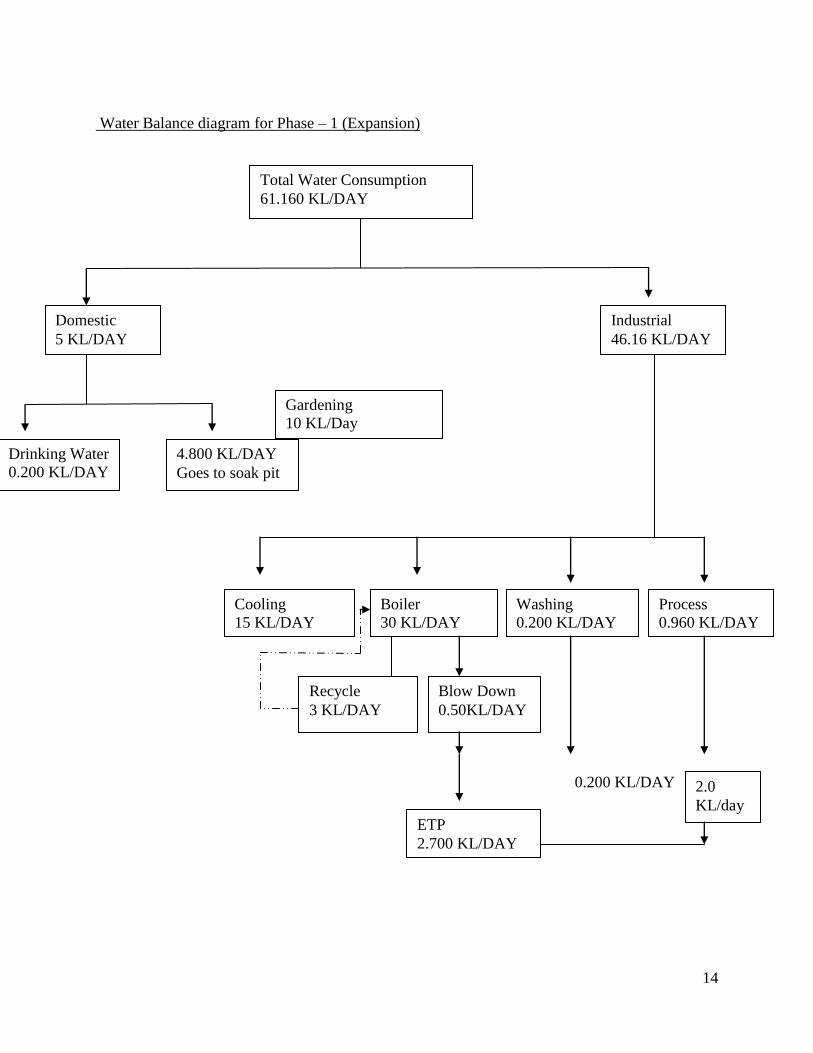
Water Balance diagram for Phase – 1 (Expansion)
0.200 KL/DAY
2
Total Water Consumption
61.160 KL/DAY
Domestic
5 KL/DAY
Industrial
46.16 KL/DAY
Drinking Water
0.200 KL/DAY
4.800 KL/DAY
Goes to soak pit
Process
0.960 KL/DAY
Washing
0.200 KL/DAY
Boiler
30 KL/DAY
Cooling
15 KL/DAY
Blow Down
0.50KL/DAY
Recycle
3 KL/DAY
ETP
2.700 KL/DAY
Gardening
10 KL/Day
2.0
KL/day
15
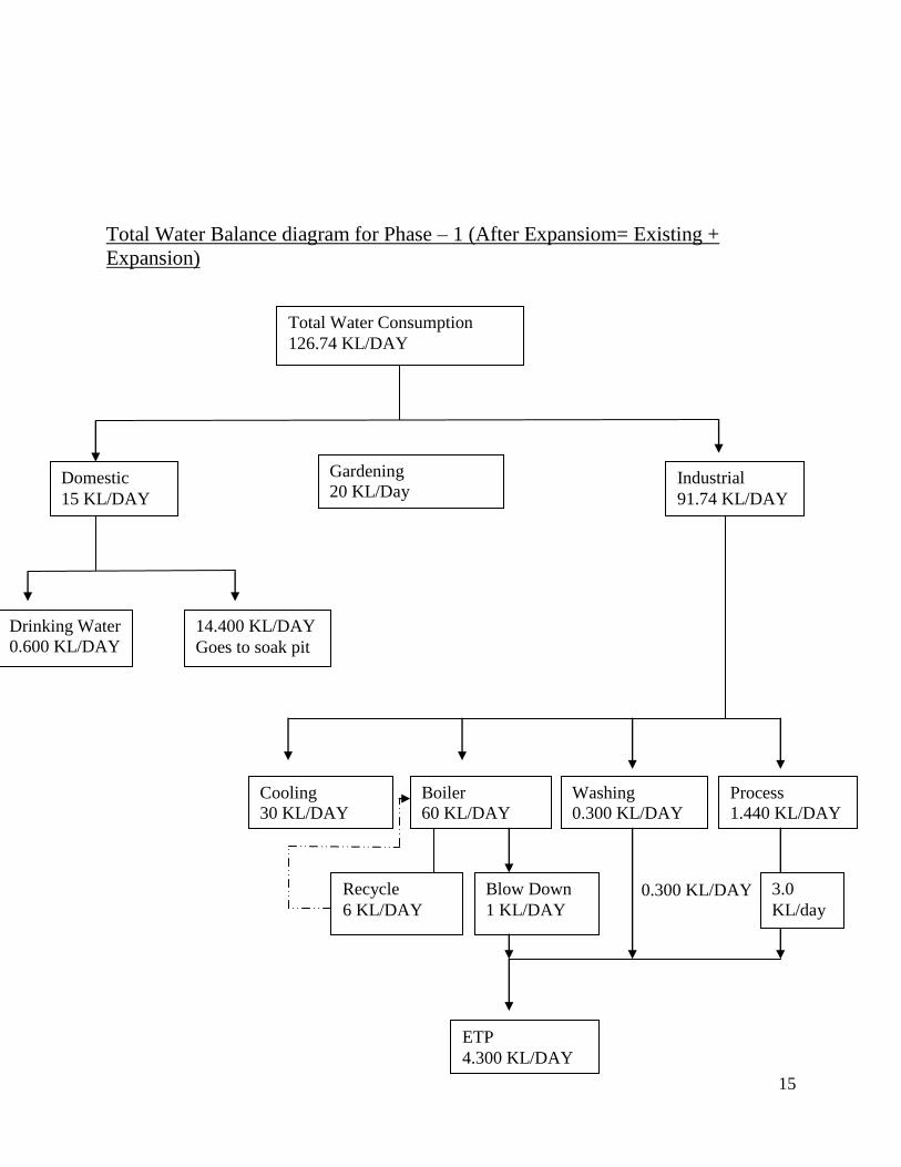
Total Water Balance diagram for Phase – 1 (After Expansiom= Existing +
Expansion)
0.300 KL/DAY
0
Total Water Consumption
126.74 KL/DAY
Domestic
15 KL/DAY
Industrial
91.74 KL/DAY
Drinking Water
0.600 KL/DAY
14.400 KL/DAY
Goes to soak pit
Process
1.440 KL/DAY
Washing
0.300 KL/DAY
Boiler
60 KL/DAY
Cooling
30 KL/DAY
Blow Down
1 KL/DAY
Recycle
6 KL/DAY
ETP
4.300 KL/DAY
Gardening
20 KL/Day
3.0
KL/day
16
Water Balance diagram for Phase – 2
Total Water Consumption
39.300 KL/DAY
Domestic
15 KL/DAY
Industrial
4.300 KL/DAY
Drinking Water
0.600 KL/DAY
14.400 KL/DAY
Goes to soak pit
Process
0.300 KL/DAY
Cooling
4 KL/DAY
NIL
Gardening
20 KL/Day
17
5. PROPOSED ETP LAY – OUT DETAILS OF ETP (Phase I)
Collection Tank
(10000 L)
Homogenizing tank or
mixing tank (10000 L)
FeSO
4.7H2
O
H2O2
Photo Fenton process vessel
(5000 L)
SLUDGE DRYING BED
1.5 M X 1.5 M X 1.5 M
3.37 m3/ each
AIR
compressor
Pump
SETTLING
TANK 5000 L
EVAPORATOR
(7500 L)
O2 supply
Heating Coil
sun
Oxidation
Process Coil for
cooling
purpose
Water Inlet
Oil circulator
pump
H2O2
Sun rays
1 2 3
2
4
5000 L/day
18
6. ETP Process:
1) Effluent from plant to be collected in collection tank.
2) Then effluent transferred in mixing tank where,
pH to be adjusted 3 to 3.5 by adding H2SO4.
FeSO4.7H2O and H2O2 added into the mixer tank
The amount of H2O2 will be half of the phenol concentration.
Fe+2
ion concentration are 1:20 of hydrogen peroxide.
3) Further waste water will be transferred into oxidation vessel.
In oxidation vessel [ PHOTO FENTON PROCESS]
O2 will be passed from the bottom side of the tank as shown in the
figure.
Maintain temperature between 30 to 35 oC by cooling system.
Phenol degradation will take place in presence of sun light or UV
lamp.
During rainy and winter season the photo fentone process will occur
into the closed vessel which contain UV lamp.
4) Further waste water to be transferred to settling tank where ETP sludge will
be settled down in conical portion. It is to be removed in sludge drying beds.
Supernatant water will be transferred into evaporation.
In evaporation,
Heating to be supplied by thermic fluid heter. Pipe line shown in the figure.
19
7. SIZE AND CAPACITY OF ETP UNIT
Sr. No.
Name of the units Volume Lit. No. of Unit
1 Collection Tank 10000 1
2 Homogenizing tank or mixing tank
10000 1
3 Photo Fenton process vessel 5000 1
4 Primary settling tank 5000 1
5 Evaporator 5000 1
6 Sludge drying bed 3375 4
8. DETAILS OF AIR EMISSI ON
Phase I
Sr. No.
Stack attached to
Height & Dia. of the stack
Total Fuel Qty. APC System
Expected Pollutant
GPCB Limit
1 Steam Boiler 3 T/hr.
( Existing)
32 m Lignite – 4 MT/D
Waste Wood - 3 MT/D
multy cyclone
dust collector
SPM,
SOx,
NOx
As
Per
GPCB
Limit
2 Thermic Fluid Heater
10 lac Kcal/hr. (Existing)
32 m
3 Steam Boiler 6 T/hr.
(Proposed)
32 m Lignite – 8 MT/D
Waste Wood - 6 MT/D
N.G
multy cyclone
dust collector 4 Thermic Fluid
Heater 20 lac Kcal/hr.
(Proposed)
32 m
5 D. G. Set (180 KVA) (Existing)
6 m Diesel – 100 L/M
N.A
6 D. G. Set (250 KVA) (Proposed)
6 m Diesel – 200 L/M
N.A
20
Phase: II
Sr. No.
Stack attached to
Height & Dia. of the stack
Total Fuel Qty. APC System
Expected Pollutant
GPCB Limit
1 Thermic Fluid Heater
15 lac Kcal/hr.
32 m Lignite – 3 MT/D
Waste Wood - 2 MT/D
multy cyclone
dust collector
SPM,
SOx,
NOx
As
Per
GPCB
Limit
2 D. G. Set (180 KVA) (Proposed)
6 m Diesel – 100 L/M
N.A
21
9. SOLID WASTE MANAGEMENT
Phase: I
Sr.
No.
Name of Waste Quantity
existing
Quantity
Propose
Total
Quantity
Schedule No.
Disposal Facility
1 ETP sludge 300
Kg/Month
600
Kg/Month
900
Kg/Month
34.3 Collected, stored & disposed off to M/s. NEPL
2 Used oil 20 L/Yr. 40 L/Yr. 60 L/Yr. 5.1 Collection, Storage & sold to registered reprocessors
3 Discarded Bags/Linears
100 Kg/Month
200 Kg/Month
300 Kg/Month
33.3 Collection, Storage & sold to authorized recycler
4 Resin waste 8,000 Kg/M 16,000 Kg/M
24,000 Kg/M
23.1 Collected, stored & disposed off to M/s.
SEPPL
Note: we will become the member of SEPPL, Bhachau, Kachchh
22
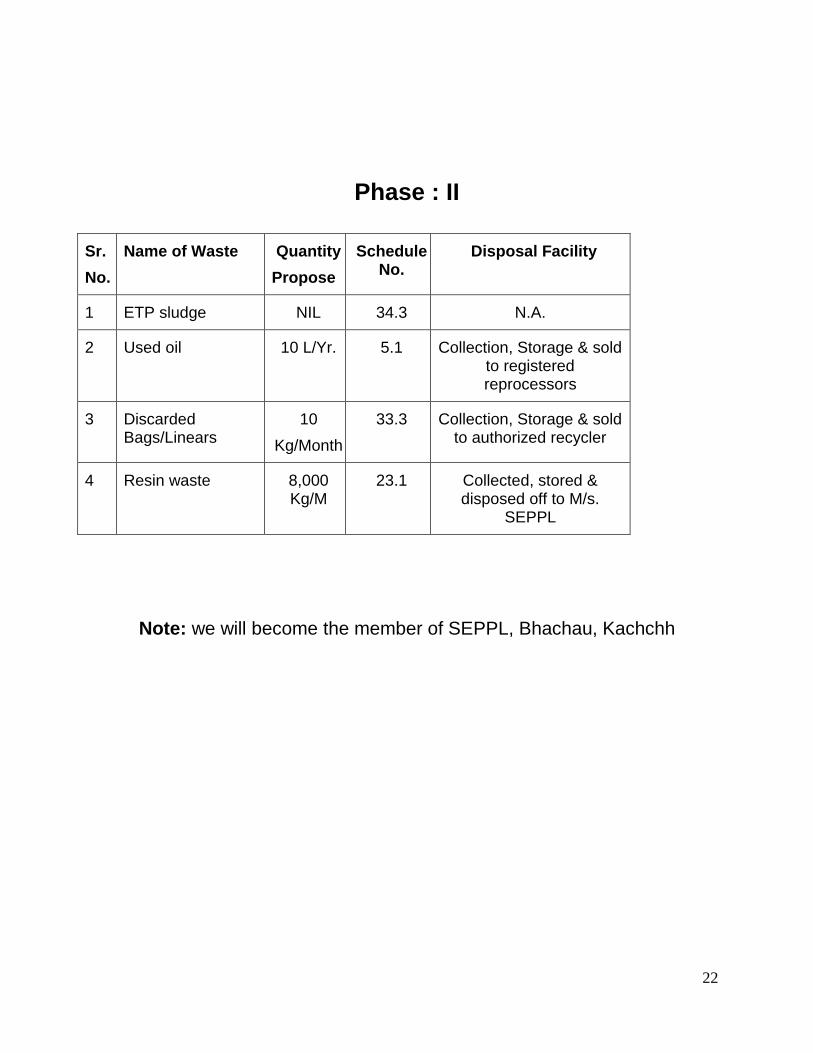
Phase : II
Sr.
No.
Name of Waste Quantity
Propose
Schedule No.
Disposal Facility
1 ETP sludge NIL 34.3 N.A.
2 Used oil 10 L/Yr. 5.1 Collection, Storage & sold to registered reprocessors
3 Discarded Bags/Linears
10
Kg/Month
33.3 Collection, Storage & sold to authorized recycler
4 Resin waste 8,000 Kg/M
23.1 Collected, stored & disposed off to M/s.
SEPPL
Note: we will become the member of SEPPL, Bhachau, Kachchh
23
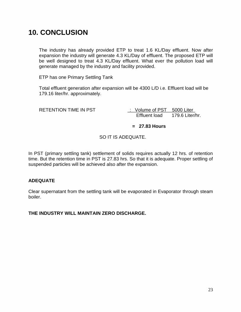
10. CONCLUSION
The industry has already provided ETP to treat 1.6 KL/Day effluent. Now after expansion the industry will generate 4.3 KL/Day of effluent. The proposed ETP will be well designed to treat 4.3 KL/Day effluent. What ever the pollution load will generate managed by the industry and facility provided. ETP has one Primary Settling Tank Total effluent generation after expansion will be 4300 L/D i.e. Effluent load will be 179.16 liter/hr. approximately.
RETENTION TIME IN PST : Volume of PST 5000 Liter Effluent load 179.6 Liter/hr. = 27.83 Hours
SO IT IS ADEQUATE.
In PST (primary settling tank) settlement of solids requires actually 12 hrs. of retention time. But the retention time in PST is 27.83 hrs. So that it is adequate. Proper settling of suspended particles will be achieved also after the expansion. ADEQUATE Clear supernatant from the settling tank will be evaporated in Evaporator through steam boiler. THE INDUSTRY WILL MAINTAIN ZERO DISCHARGE.