Page 1
ww.sciencedirect.com
i n t e r n a t i o n a l j o u r n a l o f h y d r o g e n en e r g y 4 4 ( 2 0 1 9 ) 2 7 7 9 5e2 7 8 0 5
Available online at w
ScienceDirect
journal homepage: www.elsevier .com/locate/he
Preparation of CdS-CoSx photocatalysts and theirphotocatalytic and photoelectrochemicalcharacteristics for hydrogen production
Lizi Chu a,1, Yuan Lin a,1, Yunpeng Liu a, Hongjuan Wang a, Qiao Zhang b,Yuhang Li b, Yonghai Cao a, Hao Yu a, Feng Peng b,*
a School of Chemistry and Chemical Engineering, Key Laboratory of Fuel Cell Technology of Guangdong Province,
South China University of Technology, Guangzhou, 510640, Chinab Guangzhou Key Laboratory for New Energy and Green Catalysis, School of Chemistry and Chemical Engineering,
Guangzhou University, Guangzhou, 510006, China
h i g h l i g h t s
* Corresponding author.E-mail address: [email protected] (F. Pe
1 These authors contribute equally.https://doi.org/10.1016/j.ijhydene.2019.09.0780360-3199/© 2019 Hydrogen Energy Publicati
g r a p h i c a l a b s t r a c t
� CoSx as co-catalyst is loaded on
CdS nanorod by a facile method.
� CdS-CoSx has good activity and
stability for photoelectrochemical
(PEC) reaction.
� PEC activity of CdS-CoSx as pho-
toanode for H2 production is the
same as that of CdSePt.
� An abnormal relationship between
photocurrent and hydrogen pro-
duction is found.
� The reaction network in Na2S
eNa2SO3 system for PEC H2 pro-
duction is proposed.
a r t i c l e i n f o
Article history:
Received 26 June 2019
Received in revised form
30 August 2019
Accepted 4 September 2019
Available online 30 September 2019
Keywords:
Photocatalyst
Photocatalysis
a b s t r a c t
A facile method of loading CoSx nanosheet onto CdS nanorod has been designed, and the
prepared CdS-CoSx composite catalyst exhibited significantly improved performance for
photocatalytic hydrogen evolution compared with CdS catalyst. This composite catalyst
was also used as a photoanode for photoelectrochemical (PEC) hydrogen production. The
hydrogen production rate reached 168.6 mmol cm�2 h�1 (37.77 L m�2 h�1) under the
simulated solar light, which is 2.7 times that of CdS and the same as that of CdSePt. In
addition, in the Na2SeNa2SO3 system for PEC hydrogen production, an abnormal rela-
tionship between photocurrent and the hydrogen production yield was found. By designing
a series of experiments, the photocatalytic and photoelectrochemical characteristics for
hydrogen production were reasonably revealed for the first time. In this work, the prepared
ng).
ons LLC. Published by Elsevier Ltd. All rights reserved.
Page 2
i n t e rn a t i o n a l j o u r n a l o f h y d r o g e n en e r g y 4 4 ( 2 0 1 9 ) 2 7 7 9 5e2 7 8 0 527796
Photoelectrochemical hydrogen
production
Cobalt sulfide
Cadmium sulfide
structured catalyst is easy to be recycled, and CoSx can replace precious metal Pt, showing
a promising application.
© 2019 Hydrogen Energy Publications LLC. Published by Elsevier Ltd. All rights reserved.
Introduction
Due to the exhaustion of non-renewable resources such as
fossil fuels and increasingly serious environmental pollution,
the search for clean and non-polluting sustainable energy has
attracted extensive interest of researchers around the world.
Hydrogen is an excellent energy carrier due to its advantages
of high energy density and environmental friendliness. Pho-
tocatalytic water-splitting is a promising way to produce
hydrogen. However, there is a longway to go for its large-scale
application for hydrogen production because of the relatively
low energy conversion efficiency of photocatalysis at present.
Therefore, it is still a challenge to find a photocatalytic ma-
terial with high utilization efficiency of sunlight and good
stability [1e11].
Among many photocatalytic materials, metallic sulfides
have been widely studied due to their narrow band gaps
and high utilization of solar light. CdS with the band gap of
2.4eV, as a typical semiconductor photocatalytic material,
has good response to visible light and high conduction band
position, which is favorable to reduce Hþ to hydrogen.
Therefore, it has become a research hotspot [12e18]. How-
ever, CdS is easily oxidized by photogenerated holes,
resulting in self-corrosion. Moreover, CdS has high photo-
generated carrier recombination rate, which leads to its
poor photocatalytic performance for hydrogen production
[19e21]. Therefore, loading co-catalysts or combining other
semiconductors to form heterostructures are effective ways
to improve the photocatalytic activity and stability for
hydrogen production [22e27]. It is well known that Pt and
other precious metals are excellent co-catalysts for
hydrogen evolution, but the high price and scarce resource
make them unsuitable to be applied in a large scale [28e30].
Therefore, it is highly necessary to look for cheap and
abundant non-precious metal catalysts to replace Pt and
other precious metals as co-catalysts of CdS for photo-
catalytic hydrogen production [31e38].
Recently, non-noble metal sulfide has become a research
hotspot of co-catalyst, such as Co9S8, which is a very
promising catalytic material for photocatalytic hydrogen
production because of narrow band gap and high flat band
potential [39e42]. CoSx is widely used in electrocatalytic
water decomposition and oxygen reduction with excellent
electrochemical properties [43,44]. However, as far as we
know, CoSx has not been widely used in photocatalytic
water-splitting. Qiu et al. [40] designed and synthesized a
kind of direct Z-type semiconductor heterostructure pho-
tocatalytic material Co9S8/CdS with hollow Co9S8 nano-cube
supported CdS quantum dots. In this study, hollow cube
Co(OH)2 was used as a template, and dimethyl sulfoxide
(DMSO) was used as a solvent and S source to form Co9S8 by
ion exchange with OH�. In visible light, compared with the
pure hollow Co9S8 cube and CdS quantum dot, the hydrogen
production yield of the Co9S8/CdS catalyst was improved by
134 times and 9.1 times, respectively. In addition, the
hydrogen production activity of the Co9S8/CdS catalyst
remained relatively stable for 25 h. However, this method
required the use of toxic organic reagents and complex
preparation processes. Reddy [45] designed and synthesized
a Z-type photocatalyst composed of CoeC@Co9S8 double-
shell nanocage supported mesoporous reticular CdS,
which had a hydrogen production rate of
26.69 mmol g�1 h�1 and an apparent quantum yield of 7.82%
at 425 nm for 5 h. Wang et al. synthesized a photocatalyst
with layered Co9S8@ZnIn2S4 cage heterostructure [46], which
effectively promoted the separation of photogenerated
charges and exposed the redox active sites. The hydrogen
production efficiency reached 6.25 mmol g�1 h�1 with good
stability, but the disadvantage was that the powder sample
was difficult to be recycled. Zheng et al. [41] designed and
synthesized a CoS bifunctional catalyst with the hydrogen
production rate of 1.197 mmol g�1 h�1, and the oxygen yield
of up to 65%. Lin's research group [47] used Co9S8 for the
first time to prepare a ternary TiO2/Co9S8/POM composite
material as photoanode for photoelectrochemical (PEC)
water oxidation, and the current density was as high as
1.12 mA cm�2 vs RHE at AM1.5. However, the preparation
process of this material was too complicated.
Here, a simple method was designed to synthesize a
composite catalyst by using CdS nanorod array (NRs) as skel-
eton, and then loading CoSx nanosheet onto the CdS nanorod.
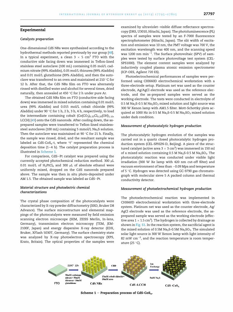
According to the previous work of our research group [48],
firstly, one-dimensional CdS NRs were grown on FTO, and
then the intermediate containing Co was loaded onto the CdS
NRs through simple chemical bath deposition (CBD) [49] in
cobalt chloride and urea solution. Finally, CdS-CoSx was ob-
tained through simple ion exchange. The preparation process
is simple and the prepared structured catalyst is easy to be
recycled. The photocatalytic hydrogen evolution performance
of CdS-CoSx composite catalyst was significantly improved
compared with that of single component catalyst CdS. The
prepared composite catalyst was used as a photoanode for
PEC hydrogen production, and its performance was compa-
rable to that of CdSePt sample. So CoSx can replace precious
metal Pt, showing a promising application. In addition, in
Na2SeNa2SO3 system for PEC hydrogen production, we found
that the measured photocurrent showed an opposite change
rule with the hydrogen production yield. By designing a series
of experiments, the reaction network for this photocatalytic
system was analyzed for the first time, and the photocatalytic
and photoelectrochemical hydrogen production process was
explained reasonably.
Page 3
i n t e r n a t i o n a l j o u r n a l o f h y d r o g e n en e r g y 4 4 ( 2 0 1 9 ) 2 7 7 9 5e2 7 8 0 5 27797
Experimental
Catalysts preparation
One-dimensional CdS NRs were synthesized according to the
hydrothermal methods reported previously by our group [48].
In a typical experiment, a clean 3 � 5 cm2 FTO with the
conductive side facing down was immersed in Teflon-lined
stainless steel autoclave (100 mL) containing 0.05 mol/L cad-
miumnitrate (99% Aladdin), 0.05mol/L thiourea (99%Aladdin)
and 0.01 mol/L glutathione (99% Aladdin), and then the auto-
clave was transferred to an oven and maintained at 210 �C for
12 h. After that, the CdS NRs film on FTO was alternately
rinsed with distilled water and alcohol for several times, dried
naturally, then annealed at 450 �C for 2 h under pure Ar.
The obtained CdS NRs film on FTO (conductive side facing
down) was immersed in mixed solution containing 0.01 mol/L
urea (99% Aladdin) and 0.015 mol/L cobalt chloride (99%
Aladdin) under 90 �C for 1 h, 2 h, 3 h, 4 h, respectively, to load
the intermediate containing cobalt (Co(CO3)0.35Cl0.20(OH)1.10,
LCCH) [49] onto the CdS nanorods. After cooling down, the as-
prepared samples were transferred to Teflon-lined stainless-
steel autoclaves (100 mL) containing 5 mmol/L Na2S solution.
Then the autoclave was maintained at 90 �C for 21 h. Finally,
the sample was rinsed, dried, and the resultant sample was
labeled as CdS-CoSx-t, where “t” represented the chemical
deposition time (1e4 h). The catalyst preparation process is
illustrated in Scheme 1.
For comparison, CdSePt catalyst was prepared using the
currently accepted photochemical reduction method. 300 mL
0.01 mol/L of H2PtCl6 and 300 mL of absolute ethanol were
uniformly mixed, dropped on the CdS nanorods prepared
above. The sample was then in situ photo-deposited under
AM 1.5. The obtained sample was labeled as CdSePt.
Material structure and photoelectric chemicalcharacterizations
The crystal phase composition of the photocatalysts were
characterized by X-ray powder diffractometry (XRD, Bruker D8
Advance). The surface microstructure and elemental map-
pings of the photocatalysts were measured by field emission
scanning electron microscope (SEM, ZEISS Merlin, In-lens,
Germany), transmission electron microscopy (TEM, JEM-
2100F, Japan) and energy dispersive X-ray detector (EDX,
Bruker, XFlash 5030T, Germany). The surface chemistry state
was analyzed by X-ray photoelectron spectroscopy (XPS,
Krato, Britain). The optical properties of the samples were
Scheme 1 e Preparation p
examined by ultravioletevisible diffuse reflectance spectros-
copy (DRS, U3010, Hitachi, Japan). The photoluminescence (PL)
spectra of samples were tested by an F-7000 fluorescence
spectrophotometer (Hitachi, Japan). The slit width of excita-
tion and emission was 10 nm, the PMT voltage was 700 V, the
excitation wavelength was 400 nm, and the scanning speed
was 1200 nm min�1. The Surface photovoltaic (SPV) of sam-
ples were tested by surface photovoltage test system (CEL-
SPS1000). The element content samples were analyzed by
inductively coupled plasma atomic emission spectrometer
(ICP-OES, Agilent 720 ES).
Photoelectrochemical performances of samples were per-
formed using CHI660D electrochemical workstation with a
three-electrode setup. Platinum net was used as the counter
electrode, Ag/AgCl electrode was used as the reference elec-
trode, and the as-prepared samples were served as the
working electrode. The tests were conducted in electrolyte of
0.5 M Na2S-0.5 M Na2SO3 mixed solution and light source was
300 W Xenon lamp with AM1.5 filter. Mott-Schottky plots ac-
quired at 1000 Hz in 0.5 M Na2S-0.5 M Na2SO3 mixed solution
under dark condition.
Measurement of photocatalytic hydrogen production
The photocatalytic hydrogen evolution of the samples was
carried out in a quartz closed photocatalytic hydrogen pro-
duction system (CEL-SPH2N-D, Beijing). A piece of the struc-
tured catalyst (active area 3 � 3 cm2) was immersed in 150 ml
of a mixed solution containing 0.5 M Na2S-0.5 M Na2SO3. The
photocatalytic reaction was conducted under visible light
irradiation (300 W Xe lamp with 420 nm cut-off filter) and
vacuum environment of less than�0.09 Mpa and temperature
of 5 �C. Hydrogen was detected using GC-9790 gas chromato-
graph with molecular sieve 5 A packed column and thermal
conductivity detector.
Measurement of photoelectrochemical hydrogen production
The photoelectrochemical reaction was implemented in
CHI660D electrochemical workstation with three-electrode
system. Platinum net was used as the counter electrode, Ag/
AgCl electrode was used as the reference electrode, the as-
prepared sample was served as the working electrode (effec-
tive area 1� 1.5 cm2). The hydrogen is collected by drainage as
shown in Fig. S1. In the reaction system, the sacrificial agent is
the mixed solution of 0.5M Na2S-0.5M Na2SO3. The simulated
solar light source is 300 W Xenon lamp with light intensity of
82 mW cm�2, and the reaction temperature is room temper-
ature (25 �C).
rocess of CdS-CoSx.
Page 4
i n t e rn a t i o n a l j o u r n a l o f h y d r o g e n en e r g y 4 4 ( 2 0 1 9 ) 2 7 7 9 5e2 7 8 0 527798
Results and discussion
Material structure characterizations
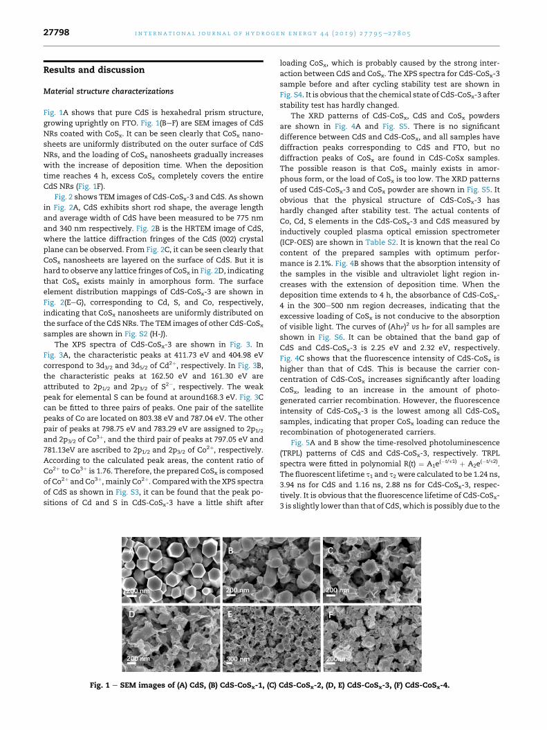
Fig. 1A shows that pure CdS is hexahedral prism structure,
growing uprightly on FTO. Fig. 1(BeF) are SEM images of CdS
NRs coated with CoSx. It can be seen clearly that CoSx nano-
sheets are uniformly distributed on the outer surface of CdS
NRs, and the loading of CoSx nanosheets gradually increases
with the increase of deposition time. When the deposition
time reaches 4 h, excess CoSx completely covers the entire
CdS NRs (Fig. 1F).
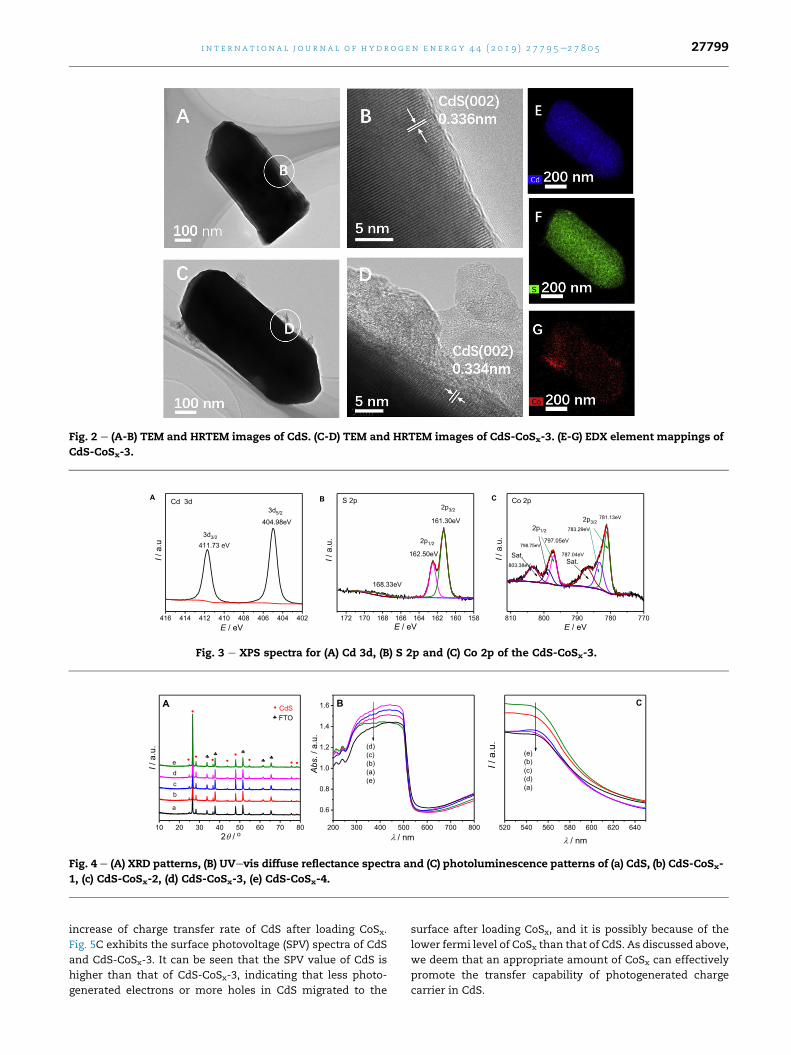
Fig. 2 shows TEM images of CdS-CoSx-3 and CdS. As shown
in Fig. 2A, CdS exhibits short rod shape, the average length
and average width of CdS have been measured to be 775 nm
and 340 nm respectively. Fig. 2B is the HRTEM image of CdS,
where the lattice diffraction fringes of the CdS (002) crystal
plane can be observed. From Fig. 2C, it can be seen clearly that
CoSx nanosheets are layered on the surface of CdS. But it is
hard to observe any lattice fringes of CoSx in Fig. 2D, indicating
that CoSx exists mainly in amorphous form. The surface
element distribution mappings of CdS-CoSx-3 are shown in
Fig. 2(EeG), corresponding to Cd, S, and Co, respectively,
indicating that CoSx nanosheets are uniformly distributed on
the surface of the CdS NRs. The TEM images of other CdS-CoSx
samples are shown in Fig. S2 (H-J).
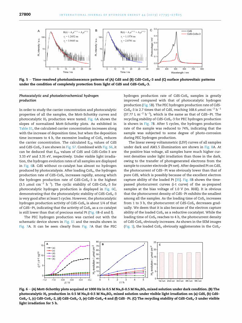
The XPS spectra of CdS-CoSx-3 are shown in Fig. 3. In
Fig. 3A, the characteristic peaks at 411.73 eV and 404.98 eV
correspond to 3d3/2 and 3d5/2 of Cd2þ, respectively. In Fig. 3B,
the characteristic peaks at 162.50 eV and 161.30 eV are
attributed to 2p1/2 and 2p3/2 of S2�, respectively. The weak
peak for elemental S can be found at around168.3 eV. Fig. 3C
can be fitted to three pairs of peaks. One pair of the satellite
peaks of Co are located on 803.38 eV and 787.04 eV. The other
pair of peaks at 798.75 eV and 783.29 eV are assigned to 2p1/2
and 2p3/2 of Co3þ, and the third pair of peaks at 797.05 eV and
781.13eV are ascribed to 2p1/2 and 2p3/2 of Co2þ, respectively.According to the calculated peak areas, the content ratio of
Co2þ to Co3þ is 1.76. Therefore, the prepared CoSx is composed
of Co2þ and Co3þ, mainly Co2þ. Comparedwith the XPS spectra
of CdS as shown in Fig. S3, it can be found that the peak po-
sitions of Cd and S in CdS-CoSx-3 have a little shift after
Fig. 1 e SEM images of (A) CdS, (B) CdS-CoSx-1, (C)
loading CoSx, which is probably caused by the strong inter-
action between CdS and CoSx. The XPS spectra for CdS-CoSx-3
sample before and after cycling stability test are shown in
Fig. S4. It is obvious that the chemical state of CdS-CoSx-3 after
stability test has hardly changed.
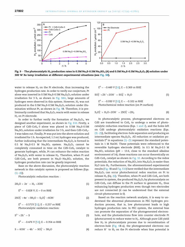
The XRD patterns of CdS-CoSx, CdS and CoSx powders
are shown in Fig. 4A and Fig. S5. There is no significant
difference between CdS and CdS-CoSx, and all samples have
diffraction peaks corresponding to CdS and FTO, but no
diffraction peaks of CoSx are found in CdS-CoSx samples.
The possible reason is that CoSx mainly exists in amor-
phous form, or the load of CoSx is too low. The XRD patterns
of used CdS-CoSx-3 and CoSx powder are shown in Fig. S5. It
obvious that the physical structure of CdS-CoSx-3 has
hardly changed after stability test. The actual contents of
Co, Cd, S elements in the CdS-CoSx-3 and CdS measured by
inductively coupled plasma optical emission spectrometer
(ICP-OES) are shown in Table S2. It is known that the real Co
content of the prepared samples with optimum perfor-
mance is 2.1%. Fig. 4B shows that the absorption intensity of
the samples in the visible and ultraviolet light region in-
creases with the extension of deposition time. When the
deposition time extends to 4 h, the absorbance of CdS-CoSx-
4 in the 300e500 nm region decreases, indicating that the
excessive loading of CoSx is not conducive to the absorption
of visible light. The curves of (Ahn)2 vs hn for all samples are
shown in Fig. S6. It can be obtained that the band gap of
CdS and CdS-CoSx-3 is 2.25 eV and 2.32 eV, respectively.
Fig. 4C shows that the fluorescence intensity of CdS-CoSx is
higher than that of CdS. This is because the carrier con-
centration of CdS-CoSx increases significantly after loading
CoSx, leading to an increase in the amount of photo-
generated carrier recombination. However, the fluorescence
intensity of CdS-CoSx-3 is the lowest among all CdS-CoSx
samples, indicating that proper CoSx loading can reduce the
recombination of photogenerated carriers.
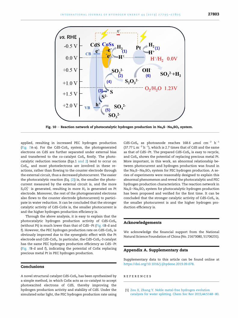
Fig. 5A and B show the time-resolved photoluminescence
(TRPL) patterns of CdS and CdS-CoSx-3, respectively. TRPL
spectra were fitted in polynomial R(t) ¼ A1e(�t/t1) þ A2e
(�t/t2).
The fluorescent lifetime t1 and t2 were calculated to be 1.24 ns,
3.94 ns for CdS and 1.16 ns, 2.88 ns for CdS-CoSx-3, respec-
tively. It is obvious that the fluorescence lifetime of CdS-CoSx-
3 is slightly lower than that of CdS,which is possibly due to the
CdS-CoSx-2, (D, E) CdS-CoSx-3, (F) CdS-CoSx-4.
Page 5
Fig. 2 e (A-B) TEM and HRTEM images of CdS. (C-D) TEM and HRTEM images of CdS-CoSx-3. (E-G) EDX element mappings of
CdS-CoSx-3.
Fig. 3 e XPS spectra for (A) Cd 3d, (B) S 2p and (C) Co 2p of the CdS-CoSx-3.
Fig. 4 e (A) XRD patterns, (B) UVevis diffuse reflectance spectra and (C) photoluminescence patterns of (a) CdS, (b) CdS-CoSx-
1, (c) CdS-CoSx-2, (d) CdS-CoSx-3, (e) CdS-CoSx-4.
i n t e r n a t i o n a l j o u r n a l o f h y d r o g e n en e r g y 4 4 ( 2 0 1 9 ) 2 7 7 9 5e2 7 8 0 5 27799
increase of charge transfer rate of CdS after loading CoSx.
Fig. 5C exhibits the surface photovoltage (SPV) spectra of CdS
and CdS-CoSx-3. It can be seen that the SPV value of CdS is
higher than that of CdS-CoSx-3, indicating that less photo-
generated electrons or more holes in CdS migrated to the
surface after loading CoSx, and it is possibly because of the
lower fermi level of CoSx than that of CdS. As discussed above,
we deem that an appropriate amount of CoSx can effectively
promote the transfer capability of photogenerated charge
carrier in CdS.
Page 6
Fig. 5 e Time-resolved photoluminescence patterns of (A) CdS and (B) CdS-CoSx-3 and (C) surface photovoltaic patterns
under the condition of completely protection from light of CdS and CdS-CoSx-3.
i n t e rn a t i o n a l j o u r n a l o f h y d r o g e n en e r g y 4 4 ( 2 0 1 9 ) 2 7 7 9 5e2 7 8 0 527800
Photocatalytic and photoelectrochemical hydrogenproduction
In order to study the carrier concentration and photocatalytic
properties of all the samples, the Mott-Schottky curves and
photocatalytic H2 production were tested. Fig. 6A shows the
slopes of normalized Mott-Schottky plots. As exhibited in
Table S1, the calculated carrier concentration increases along
with the increase of deposition time, but when the deposition
time increases to 4 h, the excessive loading of CoSx reduces
the carrier concentration. The calculated ECB values of CdS
and CdS-CoSx-3 are shown in Fig. S7. Combined with Fig. S6, it
can be deduced that EVB values of CdS and CdS-CoSx-3 are
3.33 eV and 3.35 eV, respectively. Under visible light irradia-
tion, the hydrogen evolution rates of all samples are displayed
in Fig. 6B. CdS without co-catalyst has almost no hydrogen
produced by photocatalysis. After loading CoSx, the hydrogen
production rate of CdS-CoSx increases rapidly, among which
the hydrogen production rate of CdS-CoSx-3 is the highest
(3.5 mmol cm�2 h�1). The cyclic stability of CdS-CoSx-3 for
photocatalytic hydrogen production is displayed in Fig. 6C,
demonstrating that the photocatalytic stability of CdS-CoSx-3
is very good after at least 5 cycles. However, the photocatalytic
hydrogen production activity of CdS-CoSx is about 1/4 of that
of CdSePt, indicating that the activity of CoSx as a co-catalyst
is still lower than that of precious metal Pt (Fig. 6B-d and f).
The PEC hydrogen production was carried out with the
schematic device shown in Fig. S1 and the results shown in
Fig. 7A. It can be seen clearly from Fig. 7A that the PEC
Fig. 6 e (A) Mott-Schottky plots acquired at 1000 Hz in 0.5 M Na2S
photocatalytic H2 production in 0.5 M Na2S-0.5 M Na2SO3 mixed
CoSx-1, (c) CdS-CoSx-2, (d) CdS-CoSx-3, (e) CdS-CoSx-4 and (f) Cd
light irradiation for 5 h.
hydrogen production rate of CdS-CoSx samples is greatly
improved compared with that of photocatalytic hydrogen
production (Fig. 5B). The PEC hydrogen production rate of CdS-
CoSx-3 is 2.7 times that of CdS, reaching 168.6 mmol cm�2 h�1
(37.77 L m�2 h�1), which is the same as that of CdSePt. The
recycling stability of CdS-CoSx-3 for PEC hydrogen production
is shown in Fig. 7B. After 5 cycles, the hydrogen production
rate of the sample was reduced to 74%, indicating that the
sample was subjected to some degree of photo-corrosion
during PEC hydrogen production.
The linear sweep voltammetric (LSV) curves of all samples
under dark and AM1.5 illumination are shown in Fig. 8A. At
the positive bias voltage, all samples have much higher cur-
rent densities under light irradiation than those in the dark,
owing to the transfer of photogenerated electrons from the
sample to counter electrode (Pt net). After deposited Pt on CdS,
the photocurrent of CdSePt was obviously lower than that of
pure CdS, which is possibly because of the excellent electron
capture ability of the loaded Pt [35]. Fig. 8B shows the time-
passed photocurrent curves (i-t curve) of the as-prepared
samples at the bias voltage of 1.0 V (vs. RHE). It is obvious
that the photocurrent density of CdSePt exhibits the smallest
among all the samples. As the loading time of CoSx increases
from 1 to 3 h, the photocurrent of CdS-CoSx decreases grad-
ually. We deem that it is also because of the electron capture
ability of the loaded CoSx as a reductive cocatalyst. While the
loading time of CoSx reaches to 4 h, the photocurrent density
of CdS-CoSx obviously increases. As shown in the SEM images
(Fig. 1), the loaded CoSx obviously agglomerates in the CoSx-
-0.5 M Na2SO3 mixed solution under dark condition. (B) The
solution under visible light irradiation on (a) CdS, (b) CdS-
SePt. (C) The recycling stability of CdS-CoSx-3 under visible
Page 7
Fig. 7 e (A) The PEC hydrogen production at the potential of 0.6 V (vs. RHE) in 0.5 M Na2S-0.5 M Na2SO3 solution under 300W
Xe lamp irradiation on (a) CdS, (b) CdS-CoSx-1, (c) CdS-CoSx-2, (d) CdS-CoSx-3, (e) CdS-CoSx-4, (f) CdSePt. (B) The recycling
stability of CdS-CoSx-3 at the potential of 0.6 V (vs. RHE).
Fig. 8 e The polarization curves of samples (A), photocurrent density profiles under AM1.5 irradiation at the bias potential of
1.0 V (vs. RHE) (B) on (a) CdS, (b) CdS-CoSx-1, (c) CdS-CoSx-2, (d) CdS-CoSx-3, (e) CdS-CoSx-4 and (f) CdSePt.
i n t e r n a t i o n a l j o u r n a l o f h y d r o g e n en e r g y 4 4 ( 2 0 1 9 ) 2 7 7 9 5e2 7 8 0 5 27801
CdS-4 sample. It is reported that the bulk CoSx shows the
properties of semiconductor [40]. According to the band
structure of CoSx and CdS, the electrons on the CB of CoSxmight transfer to the CB of CdS, hence increases the photo-
current density of CdS-CoSx.
The reaction network analysis for photocatalytic hydrogenproduction
In the general PEC hydrogen production process, the photo-
electrons of the working electrode are transferred to the
counter electrode Pt by the external circuit to generate
hydrogen. Therefore, the larger photocurrent corresponds to
the higher photoelectrochemical hydrogen production rate.
However, in this study, it is very interesting that the smaller
photocurrent resulted in the higher photoelectrochemical
hydrogen production rate. In fact, this phenomenon has also
been found in TiO2/MoS2 system [50].
In order to explain this abnormal result, a series of exper-
iments (Fig. S8) were designed to explore the reaction process
and the results were shown in Fig. 9. From Fig. 9A, it can be
seen that in 0.5 M Na2S-0.5 M Na2SO3 solution (Fig. S8A), Pt
alone produces little hydrogen.While CdS-CoSx-3 can produce
hydrogen with the average hydrogen production rate of
44 mmol cm�2 h�1 for 5 h. It should be noted that the photo-
catalytic hydrogen production rate of CdS-CoSx-3 in Fig. 9 is
much higher than that in Fig. 5 because of different reaction
temperatures and light sources. When Pt and CdS-CoSx-3
were simultaneously inserted into 0.5 M Na2S-0.5 M Na2SO3
solution (Pt and CdS-CoSx-3 were not connected, Fig. S8B), the
hydrogen production rate reaches 70 mmol cm�2 h�1, with 60%
increase based on CdS-CoSx-3. For CdS alone, the average
hydrogen production rate is 8 mmol cm�2 h�1 for 5 h. However,
the hydrogen production rate does not increase significantly
when the Pt was inserted into solution. The hydrogen pro-
duction performance of all samples was tested in the same
case of Pt (Fig. S8B), and their hydrogen production rates are
shown in Fig. S9. From these figures, all the photocatalysts
exhibit enhanced hydrogen production rates when Pt is
inserted simultaneously into the solution even if the Pt is not
connected with the photocatalysts.
To this interesting phenomenon, we deduced the reason is
that Na2S2O3 would be formed during the photocatalytic re-
action in Na2SeNa2SO3 solution, then Na2S2O3 reacts with
Page 8
Fig. 9 e The photocatalytic H2 production rates in 0.5M Na2S-0.5M Na2SO3 (A) and 0.5M Na2S-0.5M Na2S2O3 (B) solution under
300 W Xe lamp irradiation at different experimental situations (see Fig. S8).
i n t e rn a t i o n a l j o u r n a l o f h y d r o g e n en e r g y 4 4 ( 2 0 1 9 ) 2 7 7 9 5e2 7 8 0 527802
water to release H2 on the Pt electrode, thus increasing the
hydrogen production rate. In order to verify our conjecture, Pt
alone was inserted in 0.5M Na2S-0.5M Na2S2O3 solution under
irradiation for 3 h, as shown in Fig. S8A, large amounts of
hydrogen were observed in this system. However, H2 was not
produced in the 0.5M Na2S-0.5M Na2S2O3 solution under illu-
mination without Pt, as shown in Fig. 9B. Therefore, it is pre-
liminarily confirmed that Na2S2O3 reacts with water to release
H2 on Pt electrode.
In order to further verify the formation of Na2S2O3, we
designed another experiment, as shown in Fig. S10. Firstly, a
piece of CdS-CoSx-3 alone was placed in 0.5M Na2S-0.5M
Na2SO3 solution under irradiation for 3 h, and then CdS-CoSx-
3was taken out. Finally, Ptwas put into the above solution and
irradiated for 1 h. As expected, 1.2mL hydrogenwas produced,
further indicating that the intermediate Na2S2O3 is formed in
0.5 M Na2S-0.5 M Na2SO3 system. Na2S2O3 cannot be
completely consumed in time on the CdS-CoSx catalyst to
generate hydrogen, while, Pt can enhance the redox reaction
of Na2S2O3 with water to release H2. Therefore, when Pt and
CdS-CoSx are both present in Na2SeNa2SO3 solution, the
hydrogen production rate can be greatly improved.
Base on the above discussion, the photocatalytic reaction
network in this catalytic system is proposed as follows (Eqs.
(1)e(6)).
Photocatalytic reduction reaction:
2H2O þ 2e� ¼ H2 þ2OH� (1)
E0 ¼ �0.828 V; E ¼ 0 vs RHE
2SO32�þ4e�þ3H2O ¼ S2O3
2�þ6OH� (2)
E0 ¼ �0.571V [51]; E ¼ 0.257 vs RHE
Photocatalytic oxidation reaction:
S2�þ2hþ ¼ S (3)
E0 ¼ �0.476 V [51]; E ¼ 0.354 vs RHE
S þ 6OH� þ 4hþ ¼ SO32�þ 3H2O (4)
E0 ¼ �0.449 V [51]; E ¼ 0.369 vs RHE
SO32�þ2hþþ2OH� ¼ SO4
2�þ H2O (5)
E0 ¼ �0.930 V [51]; E ¼ �0.102 vs RHE
Photochemical redox reaction (on Pt surface):
S2O32�þ H2Oþ2OH� ¼ 2SO3
2�þ2H2 (6)
In photocatalytic process, photogenerated electrons on
CdS are transferred to CoSx to undergo a series of photo-
catalytic reduction reactions (Eqs. 1 and 2), and the holes left
on CdS undergo photocatalytic oxidation reactions (Eqs.
(3)e(5)), facilitating electron-hole separation and producing an
intermediate species Na2S2O3. All reduction or oxidation po-
tentials E0 in equations (1)e(5) represent the standard poten-
tials in 1 M NaOH. These potentials were referenced to the
reversible hydrogen electrode (RHE). In 0.5 M Na2S-0.5 M
Na2SO3 solution (pH ¼ 13.6, close to the standard alkaline
environment of 14), these reactions can occur theoretically on
CdS-CoSx catalyst as shown in Fig. 10. According to the redox
potentials, the reduction of Na2SO3 into Na2S2O3 is easier than
H2O into H2. Furthermore, the aforementioned experimental
results (Fig. 9B and Fig. S10) have verified that the intermediate
Na2S2O3 can occur photochemical redox reaction on Pt to
release H2 (Eq. (6)). Therefore, when Pt and CdS-CoSx are both
present in system, the produced Na2S2O3 by photocatalysis on
CdS-CoSx can diffuse to the Pt surface to generate H2, thus
enhancing hydrogen production even though two electrodes
are not connected (it can be understood that the external
circuit photocurrent is 0).
Based on the reaction network analysis, it is easy to un-
derstand the abnormal phenomenon in PEC hydrogen pro-
duction process, that is, low photocurrent leads to high
hydrogen production rate. In PEC system, the external bias
can promote the separation of the photogenerated electron-
hole, and the photoelectrons flow into counter electrode Pt
(photocurrent) to reduce water to H2. Although pure CdS yield
few H2 in photocatalysis process due to recombination of
electron-hole (Fig. 6B-a), the photogenerated electrons can
reduce Hþ to H2 on the Pt electrode when bias potential is
Page 9
Fig. 10 e Reaction network of photocatalytic hydrogen production in Na2SeNa2SO3 system.
i n t e r n a t i o n a l j o u r n a l o f h y d r o g e n en e r g y 4 4 ( 2 0 1 9 ) 2 7 7 9 5e2 7 8 0 5 27803
applied, resulting in increased PEC hydrogen production
(Fig. 7A-a). For the CdS-CoSx system, the photogenerated
electrons on CdS are further separated under external bias
and transferred to the co-catalyst CoSx firstly. The photo-
catalytic reduction reactions (Eqs.1 and 2) tend to occur on
CoSx, and most photoelectrons are involved in these re-
actions, rather than flowing to the counter electrode through
the external circuit, thus a decreased photocurrent. The easier
the photocatalytic reaction (Eq. (2)) is, the smaller the photo-
current measured by the external circuit is, and the more
S2O32� is generated, resulting in more H2 is generated on Pt
electrode. Moreover, the rest of the photogenerated electrons
also flows to the counter electrode (photocurrent) to partici-
pate in water reduction. It can be concluded that the stronger
catalytic activity of CdS-CoSx is, the smaller photocurrent is
and the higher hydrogen production efficiency is.
Through the above analysis, it is easy to explain that the
photocatalytic hydrogen production activity of CdS-CoSx(without Pt) is much lower than that of CdSePt (Fig. 6B-d and
f). However, the PEC hydrogen production rate on CdS-CoSx is
obviously improved due to the synergistic effect with the Pt
electrode and CdS-CoSx. In particular, the CdS-CoSx-3 catalyst
has the same PEC hydrogen production efficiency as CdSePt
(Fig. 7B-d and f), indicating the potential of CoSx replacing
precious metal Pt in PEC hydrogen production.
Conclusions
A novel structural catalyst CdS-CoSx has been synthesized by
a simple method, in which CoSx acts as co-catalyst to accept
photoexcited electrons of CdS, thereby improving the
hydrogen production activity and stability of CdS. Under the
simulated solar light, the PEC hydrogen production rate using
CdS-CoSx as photoanode reaches 168.6 mmol cm�2 h�1
(37.77 L m�2 h�1), which is 2.7 times that of CdS and the same
as that of CdSePt. The prepared CdS-CoSx is easy to recycle,
and CoSx shows the potential of replacing precious metal Pt.
More important, in this work, an abnormal relationship be-
tween photocurrent and hydrogen production was found in
the Na2SeNa2SO3 system for PEC hydrogen production. A se-
ries of experiments were reasonably designed to explain this
abnormal phenomenon and reveal the photocatalytic and PEC
hydrogen production characteristics. The reaction network in
Na2SeNa2SO3 system for photocatalytic hydrogen production
has been proposed and verified for the first time. It can be
concluded that the stronger catalytic activity of CdS-CoSx is,
the smaller photocurrent is and the higher hydrogen pro-
duction efficiency is.
Acknowledgements
We acknowledge the financial support from the National
Natural Science Foundation of China (No. 21673080, 51706231).
Appendix A. Supplementary data
Supplementary data to this article can be found online at
https://doi.org/10.1016/j.ijhydene.2019.09.078.
r e f e r e n c e s
[1] Zou X, Zhang Y. Noble metal-free hydrogen evolutioncatalysts for water splitting. Chem Soc Rev 2015;44:5148e80.
Page 10
i n t e rn a t i o n a l j o u r n a l o f h y d r o g e n en e r g y 4 4 ( 2 0 1 9 ) 2 7 7 9 5e2 7 8 0 527804
[2] He H, Cao J, Guo M, Lin H, Zhang J, Chen Y, Chen S.Distinctive ternary CdS/Ni2P/g-C3N4 composite for overallwater splitting: Ni2P accelerating separation of photocarriers.Appl Catal B Environ 2019;249:246e56.
[3] Hu J, Zhang S, Cao Y, Wang H, Yu H, Peng F. Novel highlyactive anatase/rutile TiO2 photocatalyst with hydrogenatedheterophase interface structures for photoelectrochemicalwater splitting into hydrogen. ACS Sustainable Chem Eng2018;6:10823e32.
[4] Liu X, Iocozzia J, Wang Y, Cui X, Chen Y, Zhao S, Li Z, Lin Z.Noble metal-metal oxide nanohybrids with tailorednanostructures for efficient solar energy conversion,photocatalysis and environmental remediation. EnergyEnviron Sci 2017;10:402e34.
[5] Low J, Yu J, Jaroniec M, Wageh S, Al-Ghamdi AA.Heterojunction photocatalysts. Adv Mater 2017;29:1601694.
[6] Zhong D, Liu W, Tan P, Zhu A, Liu Y, Xiong X, Pan J. Insightsinto the synergy effect of anisotropic {001} and {230}facets ofBaTiO3 nanocubes sensitized with CdSe quantum dots forphotocatalytic water reduction. Appl Catal B Environ2018;227:1e12.
[7] Xiao M, Luo B, Wang SC, Wang LZ. Solar energy conversionon g-C3N4 photocatalyst: light harvesting, charge separation,and surface kinetics. J Energy Chem 2018;27:1111e23.
[8] Vu M-H, Sakar M, Nguyen Chinh-Chien. Trong-On. Do,Chemically bonded Ni cocatalyst onto the S doped g-C3N4
nanosheets and their synergistic enhancement in H2
production under sunlight irradiation. ACS SustainableChem Eng 2018;6:4194e203.
[9] Wang ZJ, Liu Z, Chen JZ, Yang HB, Luo JQ, Gao JJ, Zhang JM,Yang CJ, Jia SP, Liu B. Self-assembly of three-dimensionalCdS nanosphere/graphene networks for efficientphotocatalytic hydrogen evolution. J Energy Chem2019;31:34e8.
[10] Reddy DA, Kim EH, Gopannagari M, Kim Y, Kumar DP,Kim TK. Few layered black phosphorus/MoS2 nanohybrid: apromising co-catalyst for solar driven hydrogen evolution.Appl Catal B Environ 2019;241:491e8.
[11] Reddy DA, Park H, Ma R, Kumar DP, Lim M, Kim TK.Heterostructured WS2-MoS2 ultrathin nanosheets integratedon CdS nanorods to promote charge separation andmigration and improve solar-driven photocatalytic hydrogenevolution. ChemSusChem 2017;10:1563e70.
[12] Cao S, Yan X, Kang Z, Liang Q, Liao X, Zhang Y. Bandalignment engineering for improved performance andstability of ZnFe2O4 modified CdS/ZnO nanostructuredphotoanode for PEC water splitting. Nano Energy2016;24:25e31.
[13] Zhang J, Li W, Li Y, Zhong L, Xu C. Self-optimizingbifunctional CdS/Cu2S with coexistence of light-reduced CuOfor highly efficient photocatalytic H2 generation undervisible-light irradiation. Appl Catal B Environ 2017;217:30e6.
[14] Iqbal S, Pan Z, Zhou K. Enhanced photocatalytic hydrogenevolution from in situ formation of few-layered MoS2/CdSnanosheet-based van der Waals heterostructures. Nanoscale2017;9:6638e42.
[15] Xu Z, Yan H, Wu G, Ma G, Wen F, Lu W, Li C. Enhancement ofphotocatalytic H2 evolution on CdS by loading MoS2 ascocatalyst under visible light irradiation. J Am Chem Soc2008;130:7176e7.
[16] Wong AB, Brittman S, Yu Y, Dasgupta NP, Yang P. Core-shellCdS-Cu2S nanorod array solar cells. Nano Lett2015;15:4096e101.
[17] Reddy DA, Kim HK, Kim Y, Lee S, Choi J, Islam MJ, Kumar DP,Kim TK. Multicomponent transition metal phosphidesderived from layered double hydroxide double-shellednanocages as an efficient non-precious co-catalyst forhydrogen production. J Mater Chem 2016;4:13890e8.
[18] Xing Z, Zhang J, Cui J, Yin J, Zhao T, Kuang J, Xiu Z, Wan N,Zhou W. Recent advances in floating TiO2-basedphotocatalysts for environmental application. Appl Catal BEnviron 2018;225:452e67.
[19] Ai G, Li H, Liu S, Mo R, Zhong J. Solar water splitting by TiO2/CdS/Co-Pi nanowire array photoanode enhanced with Co-Pias hole transfer relay and CdS as light absorber. Adv FunctMater 2015;25:5706e13.
[20] Wakerley DW, Kuehnel MF, Orchard KL, Ly KH, Rosser TE,Reisner E. Solar-driven reforming of lignocellulose to H2 witha CdS/CdOx photocatalyst. Nat Energy 2017;2:17021.
[21] Ma D, Shi J-W, Zou Y, Fan Z, Ji X, Niu C, Wang L. Rationaldesign of CdS@ZnO core-shell structure via atomic layerdeposition for drastically enhanced photocatalytic H2
evolution with excellent photostability. Nano Energy2017;39:183e91.
[22] Li H, Wang X, Xu J, Zhang Q, Bando Y, Golberg D, Ma Y,Zhai T. One-dimensional CdS nanostructures: a promisingcandidate for optoelectronics. Adv Mater 2013;25:3017e37.
[23] Li Q, Li X, Wageh S, Al-Ghamdi AA, Yu J. CdS/graphenenanocomposite photocatalysts. Adv Energy Mater2015;5:1500010.
[24] Jiang D, Sun Z, Jia H, Lu D, Du P. A cocatalyst-free CdSnanorod/ZnS nanoparticle composite for high-performancevisible-light-driven hydrogen production from water. J MaterChem 2016;4:675e83.
[25] Dai K, Lv J, Zhang J, Zhu G, Geng L, Liang C. Efficient visible-light-driven splitting of water into hydrogen over surface-fluorinated anatase TiO2 nanosheets with exposed {001}facets/layered CdS-diethylenetriamine nanobelts. ACSSustainable Chem Eng 2018;6:12817e26.
[26] Reddy DA, Choi J, Lee S, Kim Y, Hong S, Kumar DP, Kim TK.Hierarchical dandelion-flower-like cobalt-phosphidemodified CdS/reduced graphene oxide-MoS2
nanocomposites as a noble-metal-free catalyst for efficienthydrogen evolution from water. Catal Sci Technol2016;6:6197e206.
[27] Wang H, Jin Z, Hao X. CoSe2/CdS-diethylenetriamine coupledwith P clusters for efficient photocatalytic hydrogenevolution. Dalton Trans 2019;48:4015e25.
[28] Liu Y, Yang S, Zhang S, Wang H, Yu H, Cao Y, Peng F. Designof cocatalyst loading position for photocatalytic watersplitting into hydrogen in electrolyte solutions. Int JHydrogen Energy 2018;43:5551e60.
[29] Reddy DA, Park H, Hong S, Kumar DP, Kim TK. Hydrazine-assisted formation of ultrathin MoS2 nanosheets forenhancing their co-catalytic activity in photocatalytichydrogen evolution. J Mater Chem 2017;5:6981e91.
[30] Yang H, Jin Z, Wang G, Liu D, Fan K. Light-assisted synthesisMoSx as a noble metal free cocatalyst formedheterojunction CdS/Co3O4 photocatalyst for visible lightharvesting and spatial charge separation. Dalton Trans2018;47:6973e85.
[31] Liang W, Chen Y, Lin Y, Wu H, Yuan R, Li Z. MoS2 as non-noble-metal co-catalyst for photocatalytic hydrogenevolution over hexagonal ZnIn2S4 under visible lightirradiations. Appl Catal B Environ 2014;144:521e7.
[32] Liu X, Liang X, Wang P, Huang B, Qin X, Zhang X, Dai Y.Highly efficient and noble metal-free NiS modified MnxCd1-xSsolid solutions with enhanced photocatalytic activity forhydrogen evolution under visible light irradiation. Appl CatalB Environ 2017;203:282e8.
[33] Fang X, Song J, Pu T, Wang C, Yin C, Wang J, Kang S, Shi H,Zuo Y, Wang Y, Cui L. Graphitic carbon nitride-stabilizedCdS@CoS nanorods: an efficient visible-light-drivenphotocatalyst for hydrogen evolution with enhanced photo-corrosion resistance. Int J Hydrogen Energy2017;42:28183e92.
Page 11
i n t e r n a t i o n a l j o u r n a l o f h y d r o g e n en e r g y 4 4 ( 2 0 1 9 ) 2 7 7 9 5e2 7 8 0 5 27805
[34] Lang D, Cheng F, Xiang Q. Enhancement of photocatalytic H2
production activity of CdS nanorods by cobalt-basedcocatalyst modification. Catal Sci & Technol 2016;6:6207e16.
[35] Lin Y, Liu Y, Li Y, Cao Y, Huang J, Wang H, Yu H, Liang H,Peng F. Dual functional CuO1ex clusters for enhancedphotocatalytic activity and stability of a Pt cocatalyst in anoverall water-splitting reaction. ACS Sustainable Chem Eng2018;6:17340e51.
[36] Lin Y, Yang S, Liu Y, Zhang S, Wang H, Yu H, Peng F. In-situphoto-deposition CuO1-x cluster on TiO2 for enhancedphotocatalytic H2 production activity. Int J Hydrogen Energy2017;42:19942e50.
[37] Zhang L, Jin Z, Ma X, Zhang Y, Wang H. Properties of ironvanadate over CdS nanorods for efficient photocatalytichydrogen production. New J Chem 2019;43:3609e18.
[38] Yang H, Jin Z, Liu D, Fan K, Wang G. Visible light harvestingand spatial charge separation over the creative Ni/CdS/Co3O4
photocatalyst. J Phys Chem C 2018;122:10430e41.[39] Zhang F, Zhuang H-Q, Song J, Men Y-L, Pan Y-X, Yu S-H.
Coupling cobalt sulfide nanosheets with cadmium sulfidenanoparticles for highly efficient visible-light-drivenphotocatalysis. Appl Catal B Environ 2018;226:103e10.
[40] Qiu B, Zhu Q, Du M, Fan L, Xing M, Zhang J. Efficient solarlight harvesting CdS/Co9 S8 hollow cubes for Z-schemephotocatalytic water splitting. Angew Chem Int Ed2017;56:2684e8.
[41] Zheng M, Ding Y, Yu L, Du X, Zhao Y. In Situ grown pristinecobalt sulfide as bifunctional photocatalyst for hydrogen andoxygen evolution. Adv Funct Mater 2017;27:1605846.
[42] Yu Z, Meng J, Xiao J, Li Y, Li Y. Cobalt sulfide quantum dotsmodified TiO2 nanoparticles for efficient photocatalytichydrogen evolution. Int J Hydrogen Energy 2014;39:15387e93.
[43] Lin C-Y, Mersch D, Jefferson DA, Reisner E. Cobalt sulphidemicrotube array as cathode in photoelectrochemical watersplitting with photoanodes. Chem Sci 2014;5:4906e13.
[44] Kung CW, Chen HW, Lin CY, Huang KC, Vittal R, Ho KC. CoSacicular nanorod arrays for the counter electrode of anefficient dye-sensitized solar cell. ACS Nano2012;6:7016e25.
[45] Reddy DA, Park H, Gopannagari M, Kim EH, Lee S, Kumar DP,Kim TK. Designing CdS mesoporous networks on MOFderived Co-C@Co9S8 double-shelled nanocages as a redox-mediator-free Z-scheme photocatalyst with superiorphotocatalytic efficiency. ChemSusChem 2017;11:245e53.
[46] Wang S, Guan BY, Wang X, Lou XWD. Formation ofhierarchical Co9S8@ZnIn2S4 heterostructured cages as anefficient photocatalyst for hydrogen evolution. J Am ChemSoc 2018;140:15145e8.
[47] Liu R, Sun Z, Song X, Zhang Y, Xu L, Xi L. Toward non-precious nanocomposite photocatalyst: an efficient ternaryphotoanode TiO2 nanotube/Co9S8/polyoxometalate forphotoelectrochemical water splitting. Appl Catal A-Gen2017;544:137e44.
[48] Wang B, Peng F, Yang S, Cao Y, Wang H, Yu H, Zhang S.Hydrogenated CdS nanorods arrays/FTO film: a highly stablephotocatalyst for photocatalytic H2 production. Int JHydrogen Energy 2018;43:17696e707.
[49] Yuan Z, Tang R, Zhang Y, Yin L. Enhanced photovoltaicperformance of dye-sensitized solar cells based on Co9S8nanotube array counter electrode and TiO2/g-C3N4
heterostructure nanosheet photoanode. J Alloy Comp2017;691:983e91.
[50] Liu Y, Li Y, Peng F, Lin Y, Yang S, Zhang S, Wang H, Cao Y,Yu H. 2H- and 1T- mixed phase few-layer MoS2 as a superiorto Pt co-catalyst coated on TiO2 nanorod arrays forphotocatalytic hydrogen evolution. Appl Catal B Environ2019;241:236e45.
[51] Weast RC, Astle MJ, Beyer WH. CRC handbook of chemistryand physics. Boca Raton, FL: CRC press; 1988.