Price - $3.00 INSTALLATION, OPERATING AND SERVICE INSTRUCTIONS ECCS CONTROL SYSTEM ON/OFF & MODULATION Your Local Thermal Solutions Representative: g n i k e e s n e h W . r o t c a r t n o c g n i t a e h r u o y l l a c l e n a p s i h t r o , t n a l p g n i t a e h e h t o t s r i a p e r d n a e c i v r e s r o F . l e b a l g n i t a r n o n w o h s s a r e b m u n l a i r e s d n a l e d o m r e l i o b e d i v o r p , r e r u t c a f u n a m e h t m o r f n o i t a m r o f n i m e t s y S l o r t n o C S C C E r e b m u N l a i r e S m e t s y S e p y T r o t c a r t n o C g n i t a e H s s e r d d A r e b m u N e n o h P 81456003R2-12/05
Transcript
Price - $3.00
INSTALLATION, OPERATING ANDSERVICE INSTRUCTIONSECCS CONTROL SYSTEM
NOTE: The equipment shall be installed in accordance with those installation regulations required in the area where theinstallation is to be made. These regulations shall be carefully followed in all cases. Authorities having jurisdictionshall be consulted before installations are made.
All wiring on boilers installed in the USA shall be in accordance with the National Electrical Code and/or local regulations.
All wiring on boilers installed in Canada shall be in accordance with the Canadian Electrical Code and/or local regulations.
IMPORTANT INFORMATION - READ CAREFULLY
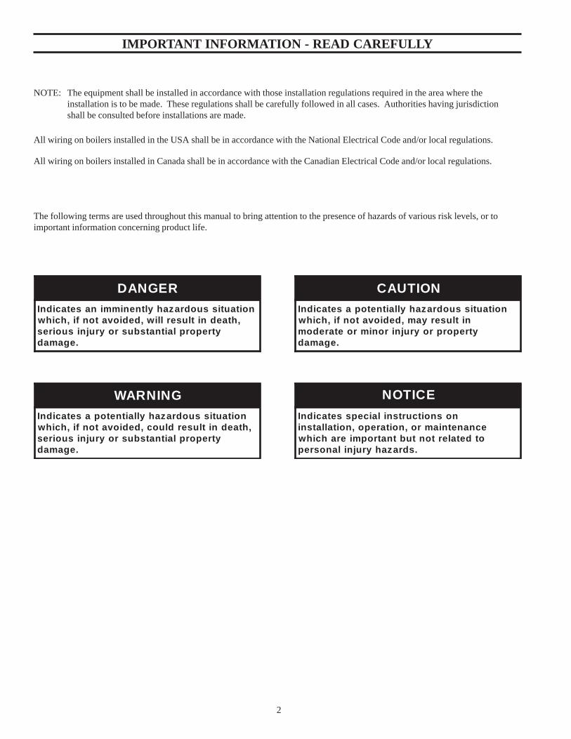
The following terms are used throughout this manual to bring attention to the presence of hazards of various risk levels, or toimportant information concerning product life.
3.2.1. Panel3.2.2. System Water Temp Sensor3.2.3. Outdoor Air Temp Sensor Figure 3.1: Panel Mounting Layout .... 10
3.3. Electrical ....................................................... 113.3.1. General3.3.2. Wiring Power Supply to Panel3.3.3. Wiring Panel to Boilers3.3.4. Wiring Panel to SensorsFigure 3.2: Panel Layout ............................ 12Figure 3.3: System Wiring .......................... 13Figure 3.4: ECCS Panel Wiring ................... 14Figure 3.5: Boiler Wiring Diagram .............. 15
Section 4. Setting the Modbus Module Address ............. 164.1. Communication Setup for Boilers ................. 164.2. Setting the Address of the Honeywell Modbus Module .......................................... 164.3. Setting the Modbus Address of the Fireye Micro M ........................................................ 16
Section 5. Touch Screen Programming .............................. 195.1. Screen Description ....................................... 195.2. General Guidelines for Using the Touchscreen ................................................. 19
Figure 5.1 Touch Screen Login .................. 19Figure 5.2 Main Screen .............................. 20Figure 5.3 System Setup Screen ................. 20Figure 5.4 Lead Lag Trigger Setup Screen . 21Figure 5.5 Sequence and Rotation Screen . 22Figure 5.6 Outdoor Reset Setup Screen ..... 23Figure 5.7 Boiler Parameters Screen ........... 23Figure 5.8 Alarm History Screen ................ 24Figure 5.9 Alarm Pop Up Screen ................ 24Figure 5.10 Warm Weather Shutdown Screen ....................................... 25Figure 5.11 Initial Setup Screen ................. 25Figure 5.12 Trend Screen ........................... 26Figure 5.13 Trend Screen Zoom Control .... 26Figure 5.14 Time/Date Screen ...................... 27
Section 7. Appendix ......................................................... 307.A. Temperature Controller Operation for Modulating Boilers (Modbus) ....................... 307.1. Description ................................................... 307.2. Setup ............................................................ 307.3. Modbus Version Used on Boilers
Controlled by the ECCS System ..................... 30Figure 7.1 Process Data ............................. 30
7.4. Adjustments ................................................. 317.5. System Specifications .................................. 31
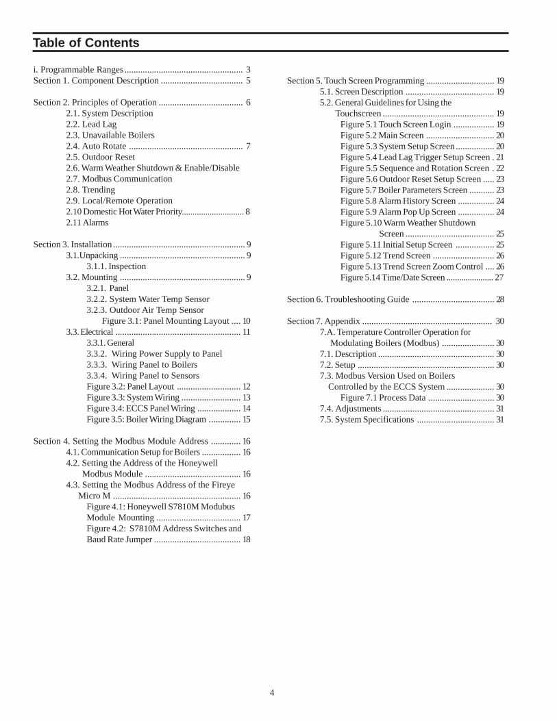
Table of Contents
5
COMPONENT DESCRIPTION Part #
1) ECCS Control Panel– houses the touch screen, PLC, analog input/output card, and terminal strips. ...................... 60156400Built to UL 508A Standard. Refer to Figure 2, Panel Layout
2) System water temperature sensor with Thermowell .................................................................................................. 80160721RTD Pt 1000
3) Outdoor air temperature sensor ................................................................................................................................. 80160722RTD Pt. 1000
7) Analog Input Module ............................................................................................................................................................... 801609114 (4-20 ma or 0-10 Vsignal inputs)1 (output)
Components in the boiler that interface with the ECCS panel.
10) Modbus version of the boiler temperature controller ................................................................................................ 80160908
11) Honeywell Modbus Module for the Flamesafeguard. ............................................................................................... 80160909
Section 1: Component Description
6
2.2.2. There is a sequence preprogrammed from thefactory as a default of: Lead = boiler 1, Lag #1 =boiler 2, Lag #2 = boiler 3, etc., in sequential order.Sequence can be changed to any order that isdesired. Numbers cannot be duplicated or out ofrange.
2.2.3. To change the lead lag sequence go to theSEQUENCE AND ROTATION SCREEN(Figure 5.5). From the main screen press the systemsetup button, then the Enter Lead Lag Sequencebutton.
2.2.4. The system will turn on the lead boiler when thetemperature drops below the System ON POINT. Theboiler will turn the lead off only if it is the onlyboiler running and the temperature is above theSystem OFF POINT.
The ECCS system turns on additional boilers when thefiring rate of the lead boiler rises above the STARTTRIGGER (See Figure 5.4: Lead Lag Trigger SetupScreen) point for the length of time in the BOILERSTART DELAY box. The START TRIGGER is thepercentage of the firing rate that a modulating boilermust reach in order to start the delay timer. Once thedelay timer finishes timing, the next boiler in thesequence will start. If the firing rate drops below theSTART TRIGGER before the timer is complete, thetimer will reset.
ON/OFF boilers will sequence in accordance with theSystem ON and OFF POINTS. See Figure 5.4 underSetpoint differential.
2.3. UNAVAILABLE BOILERS
2.3.1. If a boiler is unavailable for any one of thefollowing reasons the LL sequence will remove themand adjust the sequence until they become availableagain. The purpose of this is to save time betweenstages if there is an unavailable boiler. If thedesired lead boiler is unavailable, Lag #1 willbecome the lead and other boilers will shiftaccordingly. The program will rotate based on thesequence that has been entered onto the screen.
Flame fail – If the boiler has a flame failure the boilerwill be removed from the LL sequence until the unithas been reset.
Boiler in Local mode – If the Local/Remote switch isin Local the boiler will be removed from the LLsequence until the unit has been placed back inRemote.
2.1 SYSTEM DESCRIPTION
The ECCS (Electronic Controls and CommunicationSystem) is a Lead Lag sequencer for modulating andon/off boilers capable of auto rotation, Outdoor reset,and communication using a Modbus protocol.
All the control signals between the boiler and the ECCSpanel are transmitted over a 3 wire shielded cable usingthe Modbus protocol. This includes the enable/disablesignal, the modulating signal, and the local/remotesignal.
System water temperature is continuously monitoredthrough the header water temperature sensor. Thesystem compares this temperature to the setpoint whichis fixed or generated from the outdoor reset curve. Ifthe system water temperature falls below the adjustablesystem ON POINT set on the screen (refer to Figure5.3) the lead boiler will turn on via a signal from theECCS system. For a modulating boiler, The PIDcontrol will generate a signal and send it to the boilersvia the MODBUS. If the firing rate goes above theSTART TRIGGER Point set on the screen for theamount of time set in the START DELAY, the first lagboiler will start. Once the lag boiler starts it will driveto the same firing rate as the lead boiler. Both boilerswill fire in tandem, at the same firing rate. Additionallag boilers will start by the same criteria in the orderthat set as the LEAD LAG SEQUENCE. Boilers willbe shed in the reverse order of which they came on(AKA: First On, Last Off). As load is shed the boilerswill use the STOP TRIGGER point and the STOPDELAY parameters set on the screen.
For On/Off boilers, additional boilers will be addedwhen the system water temperature drops below thesystem ON POINT for the time set in the boiler STARTDELAY. Boilers will be shed in reverse order usingthe OFF POINT and STOP DELAY parameters.
The Lead Lag (LL) system will be capable of running amaximum number of 6 boilers. Parameters in thetemperature controller and flame safeguard aretransmitted via the Modbus connection to the PLC andTouch screen.
2.2 LEAD LAG
2.2.1. In a Lead Lag (LL) system (refer to Figure 5.4),one boiler is designated as a lead boiler. The leadboiler will always be the first boiler to come on and thelast boiler to shut off. The lag boilers will alwayscome on after the lead in order of their number. Thefirst lag (lag#1) will always be the second boiler tocome on, the second lag (lag#2) will always be thethird to come on, etc. They will turn off in reverseorder.
Section 2: Principles of Operation
7
2.3.3. When a boiler becomes available again (faultcleared, switch from local to remote, etc.) the systemwill put it back in the sequence. If the desired leadbecomes available it will start immediately and mayshut down the last boiler running in the sequencedepending on how many boilers are required.( EX: In a3 boiler system, if 2 boilers are running and only 2 arerequired when the lead comes back in service it willshut down the last lag boiler. If 2 are running and 3 arerequired it will not shut down the last lag boiler.)
2.4 AUTO ROTATE
When this function is selected by pressing the AutoRotate button (refer to Figure 5.5) the sequence willautomatically rotate based on how long the lead boilerruns. The rotation time will be set by the operator.After rotation time is reached, the Lead boiler will moveto the end of the sequence and the second boiler willbecome the lead.
When the rotation time is reached, the next boiler in thesequence will start. After the unit is running for a fewminutes the sequence will rotate, dropping out the oldlead boiler. This will insure the same amount of boilersare running before and after rotation occurs.
If the sequence is changed manually, the rotation timerwill start from the beginning.
2.5 OUTDOOR RESET
The outdoor reset function (refer to Figure 5.6)generates a setpoint based on a curve programmed onthe screen and the outdoor air temperature. Two pointsare entered and a linear curve is generated.
An RTD temperature sensor will send a signal to theRTD module for the PLC.
If outdoor reset is enabled through a switch on thescreen, the setpoint will be generated by the curve foroutdoor reset programmed on the screen.
2.6 WARM WEATHER SHUTDOWN/ENABLEDISABLE
The Warm Weather Shutdown (WWSD) (refer toFigure 5.10) function will shutdown either the boilers,the system pumps or both depending on the selectionson the WWSD screen. When the outdoor airtemperature goes above the temperature set in the highoutdoor air temperature box on the outdoor resetscreen, shutdown will occur.
The outputs for energizing a relay for controlling thesystem pumps, O:0.0 and O:0.1 (Refer to figure 3.5) willenergize when the system goes into a WWSDcondition. This is a fail-safe condition. If power is lostto the ECCS panel the pumps will still operate.
Once the OAT>HAT setting, a 60 sec timer starts. If thecondition is still true at the end of the 60 seconds theWWSD function will energize. If both the boilers andthe pumps are selected to shut down, the boilers willshut down first and 30 seconds later the system pumpswill shut down. This is done to minimize cycling aroundthe HAT, which triggers the WWSD function.
The WWSD function (or can be used as an Enable/Disable signal for all boilers) can also be activated withan external contact closure between terminals L+ andI:0.1 (Refer to figure 3.5). Ensure that the WWSDfunction is not enabled on the ECCS panel. This willfunction only when the boilers are in the remote modeand being controlled by the ECCS panel. If the boilersare in the local mode they will not be shut downby this function. There will be a 1 minute delay beforeshutdown once the contact is closed.
2.7 MODBUS COMMUNICATION
The ECCS Panel uses the Modbus protocol tocommunicate with all the boilers in the system. TheFlame Safeguard and the temperature controller bothhave Modbus communication capability. Informationsuch as faults, alarms, flame signal, cycles, hours,setpoint, and on/off points can all be communicated tothe touch screen.
2.8 TRENDING
System water temperature and outdoor air temperatureare trended for total of 8 hrs (refer to Figure 5.13). Thestandard screen shows one hour of time and that trendcan be zoomed in or out from 7.5 minutes to 8 hours.Points on trend are recorded every 30 seconds.
2.9 LOCAL/REMOTE OPERATION
A Local/Remote switch is located on the BoilerParameter screen on the touch screen (refer to Figure5.7). Some boilers may have an optional physicalselector switch on the front of the boiler.
The Local/Remote selector switch enables the boilersto be controlled from either the temperature sensor onthe individual boiler (Local) or controlled from theSystem water temperature sensor (Remote). If the boileris in the remote mode, the display on the individualboiler temperature control will flash Re F (Remote FiringRate) and the remote setpoint. If in the local mode, thedisplay will show the local setpoint without flashing.
*Fail-safe Operation*If power is lost to the ECCS panel, the boilers willautomatically revert back to the local mode.
8
2.11 ALARMSa. The ECCs will annunciate and record alarms on thescreen that come from the individual boilers. Any ofthe faults from the flamesafeguard are annunciatedthrough Modbus communication to the ECCS panel.The format for the alarms can be viewed in Fig 5.9.The alarm will indicate which boiler is in alarm, thefault code #, and a description of the 7 most commonfaults. This includes Main Flame Failure, Main FlameIgnition Failure, Pilot flame failure, Air flow failure,lockout interlock, Running interlock and Flamedetected. If it is one of the other 100+ possiblealarms it will just display the fault code for the Flamesafeguard. In addition there are alarms for High watertemperature(above 230F), Low water temperature(below 120F), and communication failure.A communication failure occurs when thecommunication over the Modbus is interrupted byeither losing power to the boiler or there is a break inthe wiring.
b. The ECCS stores 100+ alarms in the historyscreen. Every alarm is time and date stamped when itOccurs, when it was Acknowledged, and when it wasCleared. See Fig 5.8. The screen does not have anypermanent memory so if the power is turned off to thepanel the alarm history is lost.
c. As long as an alarm is active, there will be a smallbox with an exclamation point in it at the bottom ofthe screen. This will also have the # of activealarms at the bottom of the box.
d. External alarm indication – A 24vdc relay(suppliedby others) can be power by the ECCS betweenterminals O:0.7 and M for an alarm indication. Referto Fig 3.4.
2.10 DOMESTIC HOT WATER (DHW) PRIORITYDomestic hot water priority is accomplished byproviding a contact closure to the ECCS panel from adomestic hot water tank. The ECCS panel sends out24V on terminal L+ and receives voltage back onterminal I0:0 when DHW priority is called for. WhenI0:0 receives a signal the following sequence occurs:
1.) The control compares the DHW setpoint (which isset on the System Setup Screen, See Figure: 5.3.) to thesystem generated by Outdoor reset curve or fixedsetpoint. If the DHW setpoint is higher, the DHWsetpoint will become the new setpoint. If the DHWsetpoint is lower than the existing setpoint it will notchange the setpoint.
2.) If the system is in the WWSD mode, the systemwill be taken out of the WWSD mode and startboilers until the system water temperature is broughtup to the DHW setpoint.
2.12 EXTERNAL ENABLE/DISABLESee 2.6 Warm Weather Shut Down on page 7.
9
3.1 UNPACKING
3.1.1. Inspection
a. Inspect the shipment carefully for any signs ofdamage. All equipment is carefully manufactured,inspected and packed before shipment. Ourresponsibility ceases upon delivery of the ECCSpanel to the carrier in good condition. Theconsignee must file any claims for damage orshortage in shipment immediately against thecarrier. Thermal Solutions Products, LLC willallow noclaims for variances or shortages unlesspresented within thirty (30) days after receipt ofequipment.
b. The ECCS system will include:
(1) Panel with touch screen mounted in front door.PLC inside with terminal strips and breaker.
(1) System water temperature sensor andthermowell.
(1) Outdoor air temperature sensor.
3.2 MOUNTING
3.2.1. Panel
a. The ECCS system must be installed to conformwith the requirements of the local and stateauthority having jurisdiction, or in the absence ofsuch requirements, to the latest release of theNational Electric Code, ANSI/NFPA 70.
b. Provide clearance around panel for wiring conduitand access to panel.
Allow 26" in front of panel to allow door to beopened and personnel access to touch screen.
Allow 4” on bottom, top and sides to allowclearance for conduit.
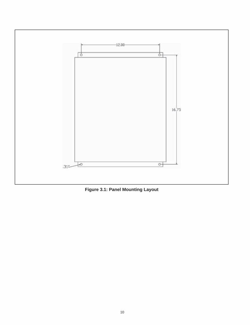
c. Mount in the vertical position. Door hinges on leftside with touch screen facing out. See Figure 3.1for physical size and details on mounting holes.
d. Panel is rated for NEMA 12 service. Whenattaching conduit, enter from bottom of panel toprevent water from gravitating down the conduitinto the box.
3.2.2. System Water Temperature Sensor
a. Mount the thermowell and sensor in a 3/4"coupling in the common header downstream of allboiler connections. Maintain a minimum distanceof 10 pipe diameters for connections. See Figure3.3 System Wiring.
3.2.3. Outdoor Air Temperature Sensora. Mount the temperature sensor on an outside wall
out of direct sunlight, preferably a north facingwall.
b. Do not mount sensor near exhausts of any kind,this may affect readings.
a. The ECCS system must be installed to conformwith the requirements of the local and stateauthority having jurisdiction, or in the absence ofsuch requirements, to the latest release of theNational Electric Code, ANSI/NFPA 70.
b. Panel is built and labeled to UL508A standards.
c. Refer to the wiring diagram supplied with thepanel, the wiring diagram for the boiler, thesystem wiring diagram, and the Panel layoutdiagram for wiring information.
d. Do not route the communication cable in conduitwith line voltage circuits.
e. Maximum wire length:Communication bus, 4000 ft.
3.3.2. Wiring Power Supply to Panel
a. The ECCS panel requires 120Vac brought intothe panel. Connect the 120V leg directly to the 4-amp breaker on the terminal strip. The Neutralwire connects to the N terminal. The ground wireconnects to the green/yellow terminal.
b. 120Vac supply to the panel must be protected bya fused disconnect, maximum 20A (by others).
3.3.3. Wiring Panel to Boilers
a. All the wiring going from the ECCS panel to theboilers is low voltage DC, 24V or less. Useminimum 22ga., 3 wire shielded cable. BeldenPart# 8771 or equivalent.
b. Modbus Signal - 3 wire, 22ga. shielded cable runfrom terminals A, B, C in the panel to terminals A,B, C in THE CLOSEST BOILER. The wire mustbe wired from the closest boiler to the next boilerand repeated until the last boiler is reached. Inother words this must be a continuous chain (daisychain configuration). A 120-ohm resistor must beadded to the last device. (See Figure 3.3 SystemWiring). The resistor is taped to the inside of thepanel for shipping.
3.3.4. Wiring Panel to Sensors
a. System water temperature sensor - Run a 2 wire,22 ga. shielded cable from terminals a+ and a- inthe ECCS panel to the wire leads on thetemperature sensor. Attach shield at panel toterminal marked shield. See Figure 3.4 ECCSPanel Wiring Diagrams.
b. Outdoor air temperature sensor - Run a 2 wire, 22ga. shielded cable from terminals b+ and b- in theECCS panel to the wire leads on the outdoortemperature sensor. Attach shield at panel toterminal marked shield. See Figure 3.4 ECCSPanel Wiring Diagram.
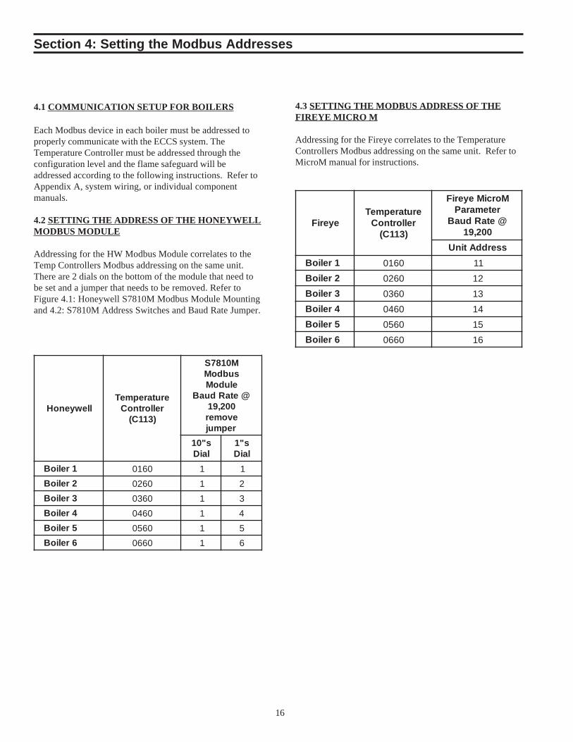
Each Modbus device in each boiler must be addressed toproperly communicate with the ECCS system. TheTemperature Controller must be addressed through theconfiguration level and the flame safeguard will beaddressed according to the following instructions. Refer toAppendix A, system wiring, or individual componentmanuals.
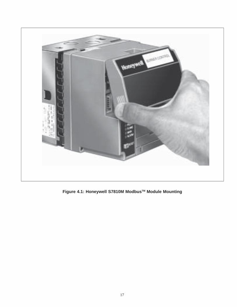
4.2 SETTING THE ADDRESS OF THE HONEYWELLMODBUS MODULE
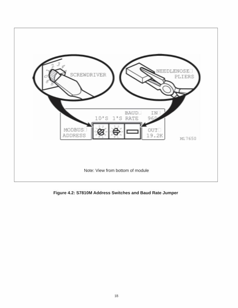
Addressing for the HW Modbus Module correlates to theTemp Controllers Modbus addressing on the same unit.There are 2 dials on the bottom of the module that need tobe set and a jumper that needs to be removed. Refer toFigure 4.1: Honeywell S7810M Modbus Module Mountingand 4.2: S7810M Address Switches and Baud Rate Jumper.
4.3 SETTING THE MODBUS ADDRESS OF THEFIREYE MICRO M
Addressing for the Fireye correlates to the TemperatureControllers Modbus addressing on the same unit. Refer toMicroM manual for instructions.
Figure 4.2: S7810M Address Switches and Baud Rate Jumper
Note: View from bottom of module
19
5.1. SCREEN DESCRIPTION
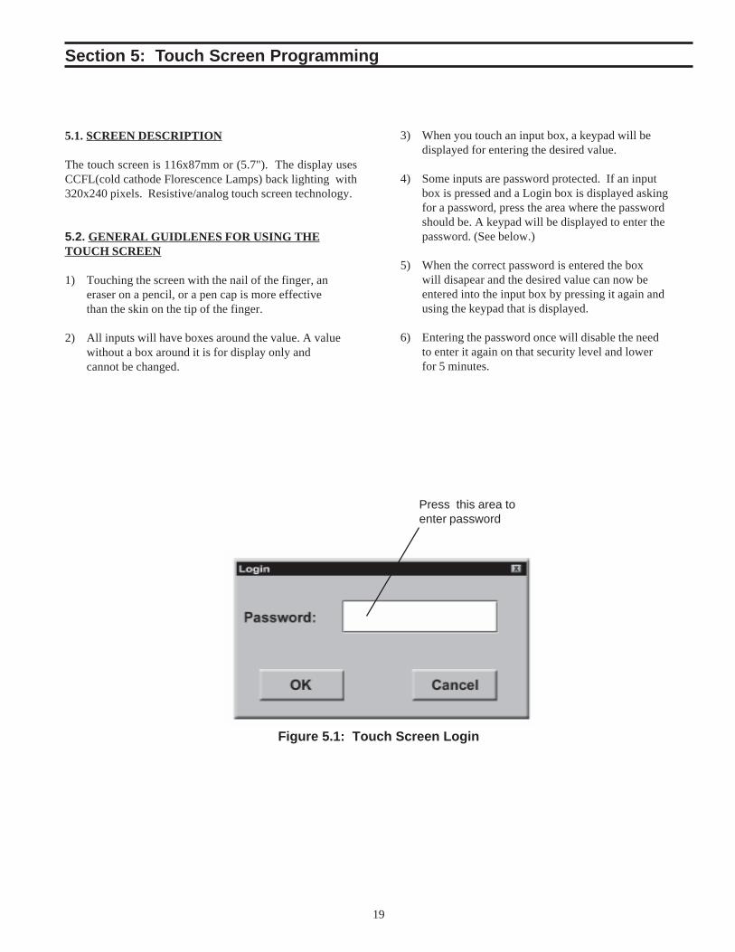
The touch screen is 116x87mm or (5.7"). The display usesCCFL(cold cathode Florescence Lamps) back lighting with320x240 pixels. Resistive/analog touch screen technology.
5.2. GENERAL GUIDLENES FOR USING THETOUCH SCREEN
1) Touching the screen with the nail of the finger, aneraser on a pencil, or a pen cap is more effectivethan the skin on the tip of the finger.
2) All inputs will have boxes around the value. A valuewithout a box around it is for display only andcannot be changed.
Press this area toenter password
3) When you touch an input box, a keypad will bedisplayed for entering the desired value.
4) Some inputs are password protected. If an inputbox is pressed and a Login box is displayed askingfor a password, press the area where the passwordshould be. A keypad will be displayed to enter thepassword. (See below.)
5) When the correct password is entered the boxwill disapear and the desired value can now beentered into the input box by pressing it again andusing the keypad that is displayed.
6) Entering the password once will disable the needto enter it again on that security level and lowerfor 5 minutes.
Section 5: Touch Screen Programming
Figure 5.1: Touch Screen Login
20
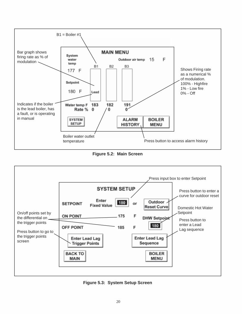
Figure 5.2: Main Screen
Figure 5.3: System Setup Screen
B1 = Boiler #1
Shows Firing rateas a numerical %of modulation.100% - Highfire1% - Low fire0% - Off
Press input box to enter Setpoint
Press button to enter acurve for outdoor reset
Bar graph showsfiring rate as % ofmodulation
Indicates if the boileris the lead boiler, hasa fault, or is operatingin manual
Boiler water outlettemperature Press button to access alarm history
Domestic Hot WaterSetpointOn/off points set by
the differential onthe trigger points
Press button to go tothe trigger pointsscreen
Press button toenter a LeadLag sequence
21
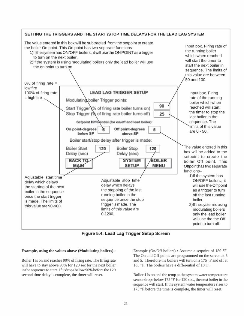
Adjustable start timedelay which delaysthe starting of the nextboiler in the sequenceonce the start triggeris made. The limits ofthis value are 90-900.
Example, using the values above (Modulating boilers) :
Boiler 1 is on and reaches 90% of firing rate. The firing ratewill have to stay above 90% for 120 sec for the next boilerin the sequence to start. If it drops below 90% before the 120second time delay is complete, the timer will reset.
Adjustable stop timedelay which delaysthe stopping of the lastrunning boiler in thesequence once the stoptrigger is made. Thelimits of this value are0-1200.
The value entered in this box will be subtracted from the setpoint to createthe boiler On point. This On point has two separate functions–
1)If the system has ON/OFF boilers, it will use the ON POINT as a triggerto turn on the next boiler.
2)If the system is using modulating boilers only the lead boiler will usethe on point to turn on.
The value entered in thisbox will be added to thesetpoint to create theboiler Off point. ThisOffpoint has two separatefunctions–
1)If the system hasON/OFF boilers, itwill use the Off pointas a trigger to turnoff the last runningboiler.
2)If the system is usingmodulating boilersonly the lead boilerwill use the the Offpoint to turn off.
SETTING THE TRIGGERS AND THE START /STOP TIME DELAYS FOR THE LEAD LAG SYSTEM
0% of firing rate =low fire100% of firing rate= high fire
Input box. Firing rate ofthe running boilerwhich when reachedwill start the timer tostart the next boiler insequence. The limits ofthis value are between50 and 100.
Input box. Firingrate of the runningboiler which whenreached will startthe timer to stop thelast boiler in thesequence. Thelimits of this valueare 0 - 50.
Example (On/Off boilers) : Assume a setpoint of 180 °F.The On and Off points are programmed on the screen at 5and 5. Therefore the boilers will turn on a 175 °F and off at185 °F. The boilers have a differential of 10°F.
Boiler 1 is on and the temp at the system water temperaturesensor drops below 175 °F for 120 sec., the next boiler in thesequence will start. If the system water temperature rises to175 °F before the time is complete, the timer will reset.
Figure 5.4: Lead Lag Trigger Setup Screen
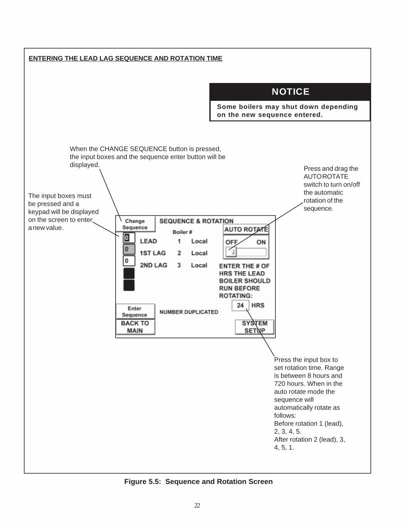
The input boxes mustbe pressed and akeypad will be displayedon the screen to entera new value.
Figure 5.5: Sequence and Rotation Screen
When the CHANGE SEQUENCE button is pressed,the input boxes and the sequence enter button will bedisplayed.
ENTERING THE LEAD LAG SEQUENCE AND ROTATION TIME
Press and drag theAUTO ROTATEswitch to turn on/offthe automaticrotation of thesequence.
Press the input box toset rotation time. Rangeis between 8 hours and720 hours. When in theauto rotate mode thesequence willautomatically rotate asfollows:Before rotation 1 (lead),2, 3, 4, 5.After rotation 2 (lead), 3,4, 5, 1.
22
ECITONgnidnepednwodtuhsyamsreliobemoS
.deretneecneuqeswenehtno
Figure 5.6: Outdoor Reset Setup Screen
The values for Setpoint,On point and Off point arefor display only and comedirectly from the boilertemperature controller viaa Modbus connection.
Figure 5.7: Boiler Parameters Screen
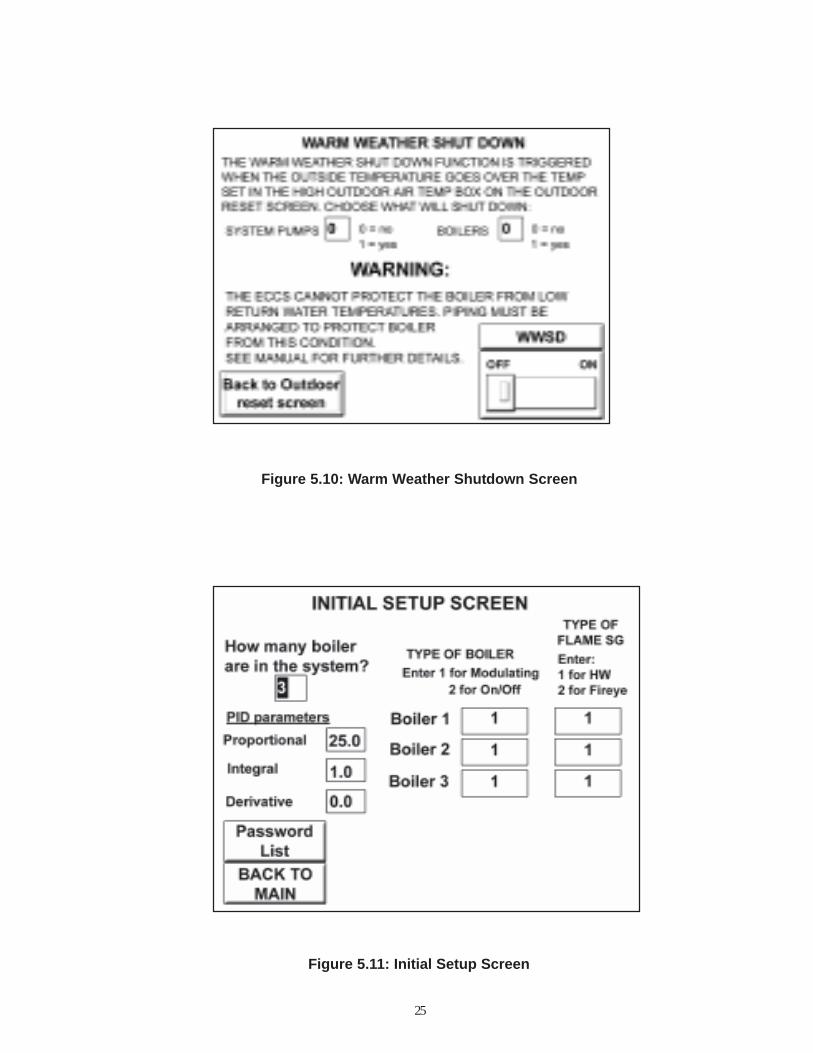
Pressing this button willgo to the screen to setup the Warm WeatherShutdown Options.
Entering temperatures in these 4 inputboxes will generate a linear curve inwhich a setpoint based on outdoor airtemperature will be generated.
This is the setpoint whichis generated based on theoutdoor air curve enteredand the outdoor airtemperature.
These values comedirectly from the FlameSafeguard via a Modbusconnection.
This is the setpoint of the boiler water at the outlet ofthe boiler. When in local the boiler will use this as itsoperating setpoint.
Outdoor Reset Switch.Press and drag toggleswitch from OFF to ON.The setpoint will nowbe generated by thecurve entered above.
Pressing and dragging thisswitch with your finger willchange control from local toremote operation.
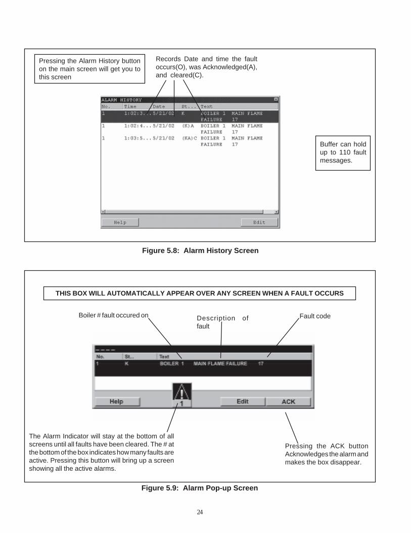
THIS BOX WILL AUTOMATICALLY APPEAR OVER ANY SCREEN WHEN A FAULT OCCURS
Fault codeDescription offault
Boiler # fault occured on
The Alarm Indicator will stay at the bottom of allscreens until all faults have been cleared. The # atthe bottom of the box indicates how many faults areactive. Pressing this button will bring up a screenshowing all the active alarms.
Pressing the ACK buttonAcknowledges the alarm andmakes the box disappear.
Pressing the Alarm History buttonon the main screen will get you tothis screen
Records Date and time the faultoccurs(O), was Acknowledged(A),and cleared(C).
24
Buffer can holdup to 110 faultmessages.
Figure 5.10: Warm Weather Shutdown Screen
Figure 5.11: Initial Setup Screen
25
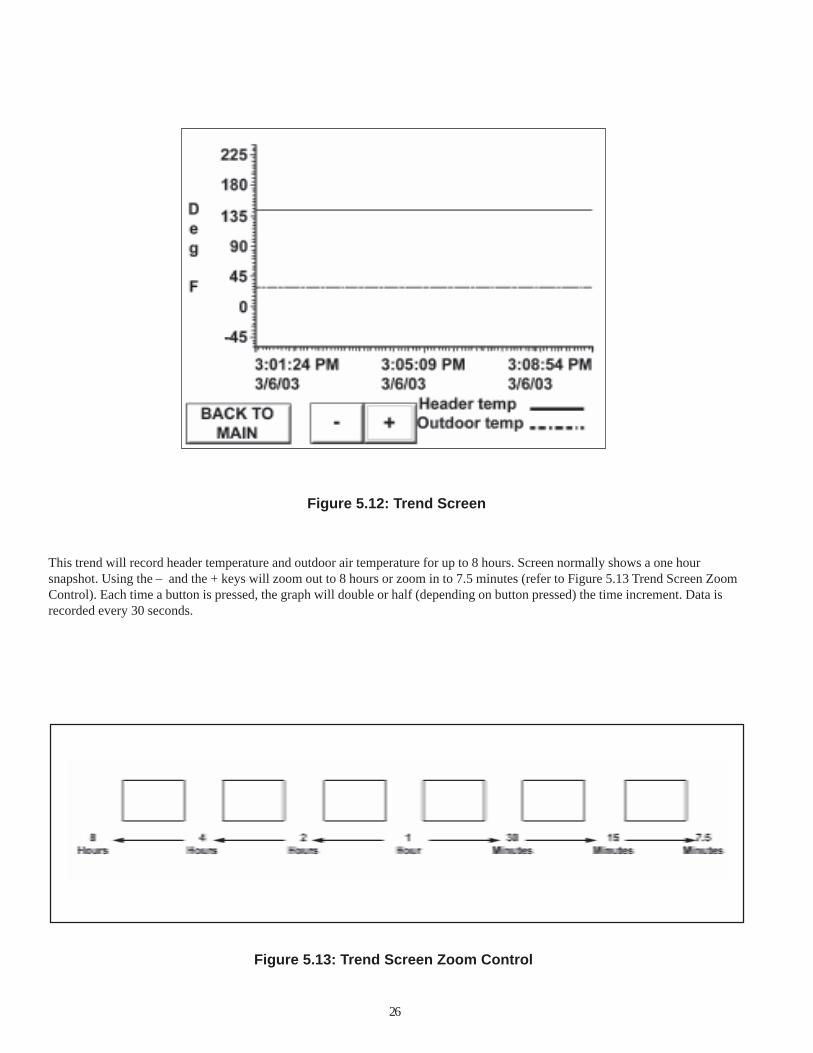
Figure 5.12: Trend Screen
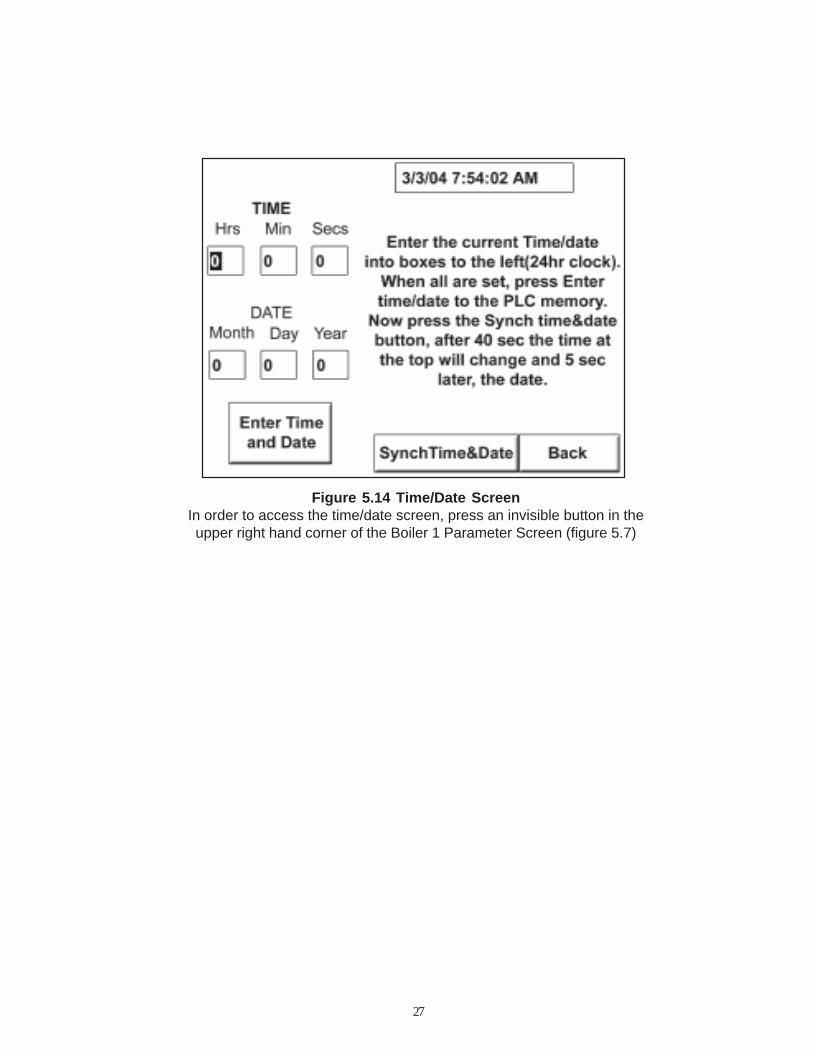
This trend will record header temperature and outdoor air temperature for up to 8 hours. Screen normally shows a one hoursnapshot. Using the – and the + keys will zoom out to 8 hours or zoom in to 7.5 minutes (refer to Figure 5.13 Trend Screen ZoomControl). Each time a button is pressed, the graph will double or half (depending on button pressed) the time increment. Data isrecorded every 30 seconds.
Figure 5.13: Trend Screen Zoom Control
26
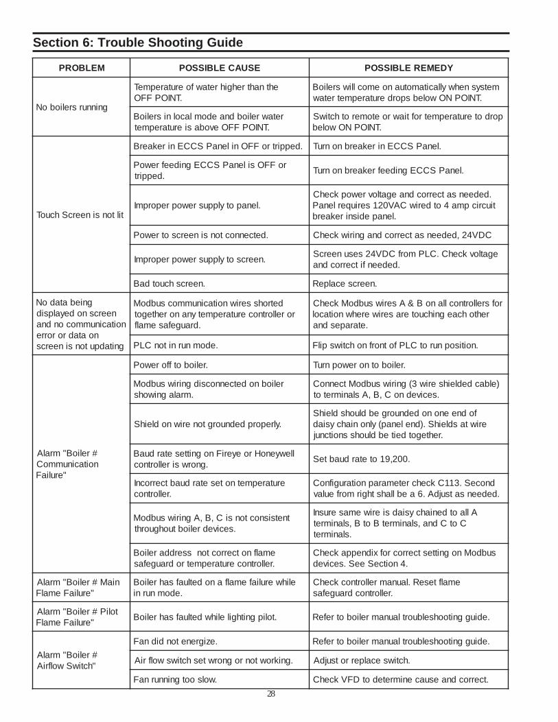
Figure 5.14 Time/Date ScreenIn order to access the time/date screen, press an invisible button in theupper right hand corner of the Boiler 1 Parameter Screen (figure 5.7)
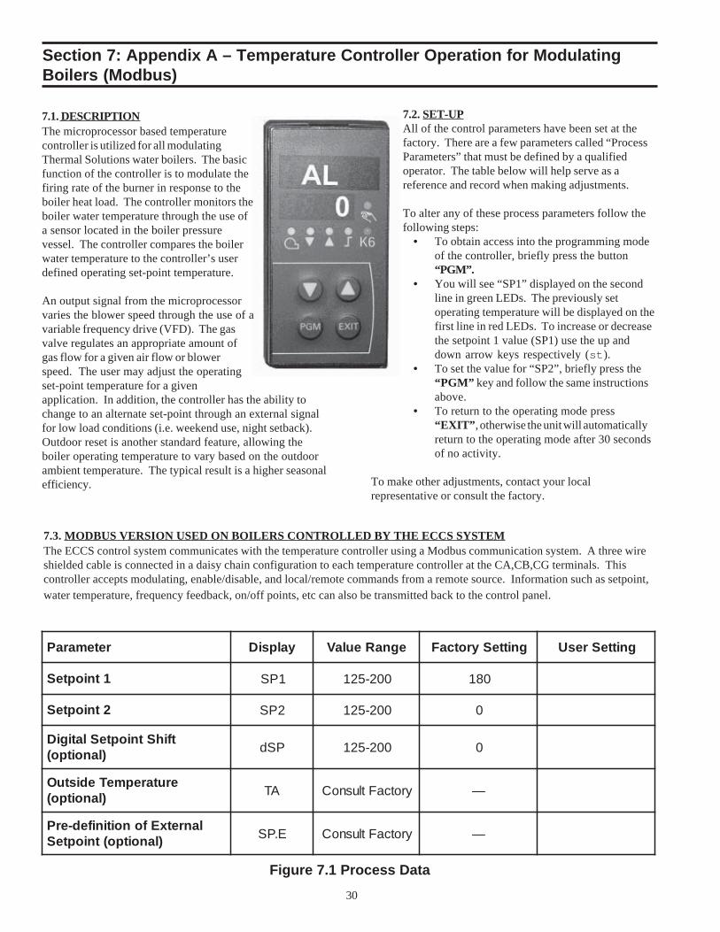
7.1. DESCRIPTIONThe microprocessor based temperaturecontroller is utilized for all modulatingThermal Solutions water boilers. The basicfunction of the controller is to modulate thefiring rate of the burner in response to theboiler heat load. The controller monitors theboiler water temperature through the use ofa sensor located in the boiler pressurevessel. The controller compares the boilerwater temperature to the controller’s userdefined operating set-point temperature.
An output signal from the microprocessorvaries the blower speed through the use of avariable frequency drive (VFD). The gasvalve regulates an appropriate amount ofgas flow for a given air flow or blowerspeed. The user may adjust the operatingset-point temperature for a givenapplication. In addition, the controller has the ability tochange to an alternate set-point through an external signalfor low load conditions (i.e. weekend use, night setback).Outdoor reset is another standard feature, allowing theboiler operating temperature to vary based on the outdoorambient temperature. The typical result is a higher seasonalefficiency.
Figure 7.1 Process Data
7.2. SET-UPAll of the control parameters have been set at thefactory. There are a few parameters called “ProcessParameters” that must be defined by a qualifiedoperator. The table below will help serve as areference and record when making adjustments.
To alter any of these process parameters follow thefollowing steps:
• To obtain access into the programming modeof the controller, briefly press the button“PGM”.
• You will see “SP1” displayed on the secondline in green LEDs. The previously setoperating temperature will be displayed on thefirst line in red LEDs. To increase or decreasethe setpoint 1 value (SP1) use the up anddown arrow keys respectively (st).
• To set the value for “SP2”, briefly press the“PGM” key and follow the same instructionsabove.
• To return to the operating mode press“EXIT”, otherwise the unit will automaticallyreturn to the operating mode after 30 secondsof no activity.
To make other adjustments, contact your localrepresentative or consult the factory.
7.3. MODBUS VERSION USED ON BOILERS CONTROLLED BY THE ECCS SYSTEMThe ECCS control system communicates with the temperature controller using a Modbus communication system. A three wireshielded cable is connected in a daisy chain configuration to each temperature controller at the CA,CB,CG terminals. Thiscontroller accepts modulating, enable/disable, and local/remote commands from a remote source. Information such as setpoint,water temperature, frequency feedback, on/off points, etc can also be transmitted back to the control panel.
Section 7: Appendix A – Temperature Controller Operation for ModulatingBoilers (Modbus)
31
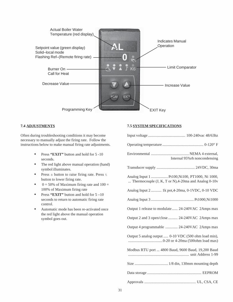
7.4 ADJUSTMENTS
Often during troubleshooting conditions it may becomenecessary to manually adjust the firing rate. Follow theinstructions below to make manual firing rate adjustments.
• Press “EXIT” button and hold for 5 -10seconds.
• The red light above manual operation (hand)symbol illuminates.
• Press s button to raise firing rate. Press tbutton to lower firing rate.
• 0 = 50% of Maximum firing rate and 100 =100% of Maximum firing rate
• Press “EXIT” button and hold for 5 –10seconds to return to automatic firing ratecontrol.
• Automatic mode has been re-activated oncethe red light above the manual operationsymbol goes out.
Actual Boiler WaterTemperature (red display)
Burner OnCall for Heat
Decrease Value
Programming Key
Limit Comparator
Increase Value
EXIT Key
Setpoint value (green display)Solid–local modeFlashing Ref–(Remote firing rate)
Indicates ManualOperation
7.5 SYSTEM SPECIFICATIONS
Input voltage ....................................... 100-240vac 48/63hz
Operating temperature ........................................... 0-120° F
Environmental ........................................ NEMA 4 external,Internal 95%rh noncondensing
Data storage ......................................................... EEPROM
Approvals ...................................................... UL, CSA, CE
NOTES
NOTES
THERMAL SOLUTIONS PRODUCTS, LLC.(“Seller”)
LIMITED WARRANTYLIMITED WARRANTY
Subject to the terms and conditions herein and except as providedbelow with respect to products or parts not manufactured byThermal Solutions Products, LLC, Seller warrants to the originalowner at the original installation site that products manufacturedby Seller (“Products”) comply, at the time of manufacture, withrecognized hydronics industry regulatory agency standards andrequirements then in effect and will be free from defects inmaterials and workmanship for a period of 3 years from date ofshipment (the “Warranty Period”) SPECIAL NOTE: Thewarranty of any boiler found to be operating as a “Water Heater”shall revert back to Thermal Solution’s standard water heaterwarranty.
For products or parts not manufactured by Thermal Solutions,the warranty obligations of Thermal Solutions shall, in allrespects, be limited to one year.
REMEDY
A. The sole remedy for breach of this warranty is expresslylimited to the repair or replacement of any part found to bedefective under conditions of normal use within theWarranty Period. Labor for removal and/or installation isnot included.
B. Warranty - The owner must notify the original installer ofthe Product and Seller (Attention: Thermal SolutionsProducts, LLC, P.O. Box 3244, Lancaster, PA 17604-3244), in writing, within the Warranty Period, providing adetailed description of all claimed defects. Transportation toa factory or other designated facility for repairs of anyproducts or items alleged defective shall, in all events, be theresponsibility and at the cost of the owner.
EXCLUSIONS
Seller shall have no liability for and this warranty does not cover:
A. Incidental, special or consequential damages, such as loss ofthe use of products, facilities or production, inconvenience,loss of time or labor expense involved in repairing orreplacing the alleged defective Product.
B. The performance of any Product under conditions varyingmaterially from those under which such Product is usuallytested under industry standards as of the time of shipment.
C. Any damage to the Product due to abrasion, erosion,corrosion, deterioration, abnormal temperatures or theinfluence of foreign matter or energy.
D. The design or operation of owner’s plant or equipment or ofany facility or system of which any Product may be made apart.
E. The suitability of any Product for any particular application.
F. Any failure resulting from misuse, modification notauthorized by Seller in writing, improper installation or lackof or improper maintenance.
G. Equipment furnished by the owner, either mounted orunmounted, or when contracted for by the owner to beinstalled or handled.
H. Leakage or other malfunction caused by:
1. Defective installations in general and specifically, anyinstallation which is made:
a. in violation of applicable state or local plumbinghousing or building codes,
b. without a certified ASME, pressure relief valve, or
c. contrary to the written instructions furnished with theunit
2. Adverse local conditions in general and, specifically,sediment or lime precipitation in the tubes and/or headersor corrosive elements in the atmosphere.
3. Misuse in general and, specifically, operation andmaintenance contrary to the written instructionsfurnished with the unit, disconnection, alteration oraddition of components or apparatus, not approved byseller, operation with fuels or settings other than thoseset forth on the rating plate or accidental or exteriordamage.
I. Production of noise, odors, discoloration or rusty water.
J. Damage to surrounding area or property caused by leakageor malfunction.
K. Costs associated with the replacement and/or repair of theunit including: any freight, shipping or delivery charges, anyremoval, installation or reinstallation charges, any materialand/or permits required for installation reinstallation orrepair, charges to return the boiler and or components.
Seller’s liability under this warranty shall not in any case exceedthe amount paid for the Product found to be defective.
THIRD-PARTY WARRANTIES
For goods or components not manufactured by Seller, thewarranty obligations of Seller shall, in all respects, conform andbe limited to one year from the date of shipment
SEVERABILITY
To the extent that any provision of this warranty would be void orprohibited under applicable law, such provisions shall be limitedin effect to the minimum extent necessary to render the remainingprovisions hereof enforceable.
NO OTHER WARRANTIES
Seller makes no implied warranty of merchantability orfitness for a particular purpose, or other warranties withrespect to any products or services except as expressly setforth in this limited warranty.