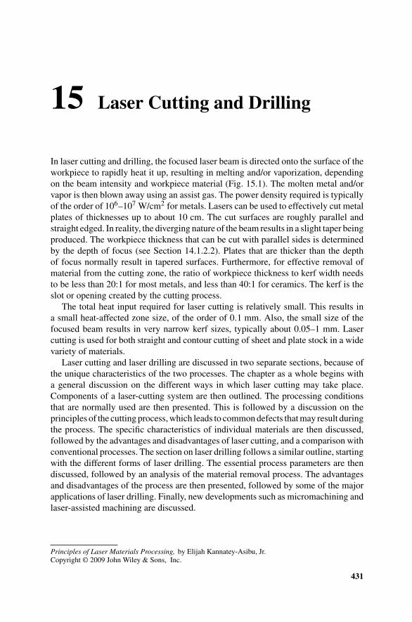
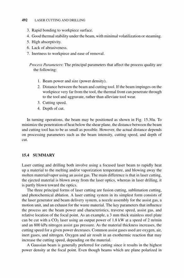
In laser cutting and drilling, the focused laser beam is directed onto the surface of theworkpiece to rapidly heat it up, resulting in melting and/or vaporization, dependingon the beam intensity and workpiece material (Fig. 15.1). The molten metal and/orvapor is then blown away using an assist gas. The power density required is typicallyof the order of 106–107 W/cm2 for metals. Lasers can be used to effectively cut metalplates of thicknesses up to about 10 cm. The cut surfaces are roughly parallel andstraight edged. In reality, the diverging nature of the beam results in a slight taper beingproduced. The workpiece thickness that can be cut with parallel sides is determinedby the depth of focus (see Section 14.1.2.2). Plates that are thicker than the depthof focus normally result in tapered surfaces. Furthermore, for effective removal ofmaterial from the cutting zone, the ratio of workpiece thickness to kerf width needsto be less than 20:1 for most metals, and less than 40:1 for ceramics. The kerf is theslot or opening created by the cutting process.
The total heat input required for laser cutting is relatively small. This results ina small heat-affected zone size, of the order of 0.1 mm. Also, the small size of thefocused beam results in very narrow kerf sizes, typically about 0.05–1 mm. Lasercutting is used for both straight and contour cutting of sheet and plate stock in a widevariety of materials.
Laser cutting and laser drilling are discussed in two separate sections, because ofthe unique characteristics of the two processes. The chapter as a whole begins witha general discussion on the different ways in which laser cutting may take place.Components of a laser-cutting system are then outlined. The processing conditionsthat are normally used are then presented. This is followed by a discussion on theprinciples of the cutting process, which leads to common defects that may result duringthe process. The specific characteristics of individual materials are then discussed,followed by the advantages and disadvantages of laser cutting, and a comparison withconventional processes. The section on laser drilling follows a similar outline, startingwith the different forms of laser drilling. The essential process parameters are thendiscussed, followed by an analysis of the material removal process. The advantagesand disadvantages of the process are then presented, followed by some of the majorapplications of laser drilling. Finally, new developments such as micromachining andlaser-assisted machining are discussed.
FIGURE 15.1 Schematic of the laser cutting process. (From LIA Handbook of Laser Mate-rials Processing. Copyright 2001, Laser Institute of America. All rights reserved.)
15.1 LASER CUTTING
15.1.1 Forms of Laser Cutting
The process of laser cutting can occur in one of the three forms:
1. Fusion cutting.
2. Sublimation cutting.
3. Photochemical ablation.
15.1.1.1 Fusion Cutting Fusion cutting involves melting of the base material,which is then ejected using a high-pressure assist gas. The assist gas may be an inertgas, in which case the energy for melting is provided entirely by the laser beam. It mayalso be oxygen (or air), which reacts with the base metal, and the resulting exothermicreaction provides additional energy to enhance the process. The term fusion or cleancutting is sometimes used to indicate inert gas assisted cutting, while the processinvolving exothermic reaction is then referred to as gas cutting. A major problemof fusion cutting is the formation of striations (valleys and peaks that run along thethickness (see Section 15.1.5.1)) on the cut surface and dross (molten material thatclings to and solidifies on the underside of the cut edge as burr (see Section 15.1.5.2))at the lower cut edge. However, the fusion cutting process is more efficient, requiringless energy per unit volume of material removed as compared to the other methods.
15.1.1.2 Sublimation Cutting In sublimation cutting, the workpiece material isvaporized along the cutting seam. This is often achieved using a pulsed beam, anda jet of inert assist gas that is coaxial with the beam is used to blow away the vaporproduced. It is limited to thin sections since more energy is required to remove a unit
LASER CUTTING 433
volume of material as compared to fusion cutting. However, it has the advantage of anarrower kerf width and higher quality surface. Pulsed beams with high peak powermay be necessary when surface quality is critical.
15.1.1.3 Photochemical Ablation Organic materials, ceramics or difficult-to-cutmaterials in general are normally cut by this method or by sublimation cutting. Organiccompounds tend to absorb ultraviolet radiation in an efficient manner. The photonenergy levels of lasers based on ultraviolet radiation range between 3.5 and 6.5 eV.This corresponds with the energy levels required for molecular bonding. For example,the energy associated with the C−C bond is roughly 4.6 eV, while that of the C−Hbond is about 4.2 eV. Compare with the photon energy levels associated with CO2and Nd:YAG lasers of about 0.12 and 1.2 eV, respectively.
As a result, when an organic material is irradiated with an ultraviolet beam, thematerial absorbs the beam’s energy in a very thin layer near the surface, of the orderof submicrons. This breaks molecular bonds, causing ablative decomposition of theirradiated area. The process occurs almost instantaneously (about 20 ns duration),and since the thermal conductivity of organic materials is relatively low, the resultingedges are well defined, with minimal thermal damage to the surrounding area. Thusthe cut region is cleaner and smoother compared to that obtained using CO2 andNd:YAG lasers. The process is sometimes referred to as cold cutting since little heatis generated.
15.1.2 Components of a Laser Cutting System
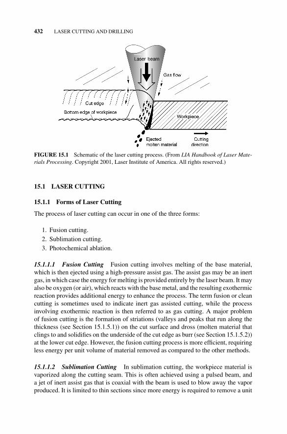
The basic components of a cutting system are illustrated in Fig. 15.2 and include
1. The laser generator that produces the beam.
2. A beam delivery system for directing the beam to the workpiece.
3. A nozzle assembly, usually integral with the focusing assembly and coaxialwith the beam, for directing the assist gas to the workpiece.
4. A motion unit for providing relative motion between the laser beam and theworkpiece.
5. An exhaust for the waste material.
The beam normally emerges from the generator horizontally and is deflected ver-tically downward by a bending mirror. The vertical orientation is used to minimizetrapping of the beam and molten material blown through the cut. The beam is thenfocused by the lens onto the workpiece. At the same time, a gas jet is directed througha nozzle attached to the tip of the focusing assembly, onto the workpiece. A typi-cal nozzle diameter would be about 1–2 mm. The delivery pressures are normallymaintained at about 3–4 bar (45–60 psi or 0.3–0.4 MPa) in the gas jet nozzle forcutting thin materials at high speeds. At high gas pressures, it is often necessary touse relatively thick lenses that can withstand the pressure. However, care has to betaken since thermal deformation of the lens increases with its thickness. Thus, at high
434 LASER CUTTING AND DRILLING
Laser beam(from generator)
Gas flow
Exhaust
Workpiece
Focusing lens
Mirror(part of beamdelivery system)
Nozzle assembly
FIGURE 15.2 Components of a laser cutting system.
power levels, say 10 kW, it is preferable to use reflective optics (mirrors) rather thantransmissive optics (lenses).
The beam is generally oriented in a direction almost normal to the workpiece sur-face, and there is a deterioration in product quality as the beam orientation deviatessignificantly from the normal direction. The distance from the nozzle tip to the work-piece surface is typically maintained constant at about 0.3 mm to minimize expansionof the gas flow. Capacitive or light sensors may be installed to measure this distance(see Section “Capacitive Transducers” in Chapter 21). The focusing unit may thenbe moved using a computer numerically controlled (CNC) third axis or a robot. Asimpler but less flexible approach involves mounting the focusing unit on rollers thatglide on the workpiece surface.
Directly opposite the nozzle, on the other side of the workpiece, an exhaust systemis provided to absorb the transmitted beam, molten debris from the cut, and exhaustvapors. This normally consists of a vacuum pump that draws the exhaust to a disposalunit.
15.1.3 Processing Conditions
The principal parameters that affect the laser cutting process include the following:
1. Beam power.
2. Beam characteristics.
LASER CUTTING 435
3. Traverse speed.
4. Assist gas type and flow.
5. Location of focal point relative to the workpiece surface.
Table 15.1 gives sample conditions for laser cutting of various materials. Each ofthese parameters are further discussed in the following sections.
15.1.3.1 Beam Power The power is the most significant of the parameters listed.An increase in power increases the maximum thickness that can be cut and/or speedat which it can be cut.
15.1.3.2 Beam Characteristics The most important beam characteristics in lasercutting operations are
1. Beam mode
2. Stability
3. Polarization
4. Beam form (pulsed or continuous wave).
Beam Mode As indicated in Section 14.1.3, the beam mode is an indication of howthe energy intensity is distributed over the beam cross section. The mode relates tothe beam’s ability to be focused, and may be compared with the sharpness of a cuttingtool. In laser cutting, it is desirable to have the beam distribution as close as possible
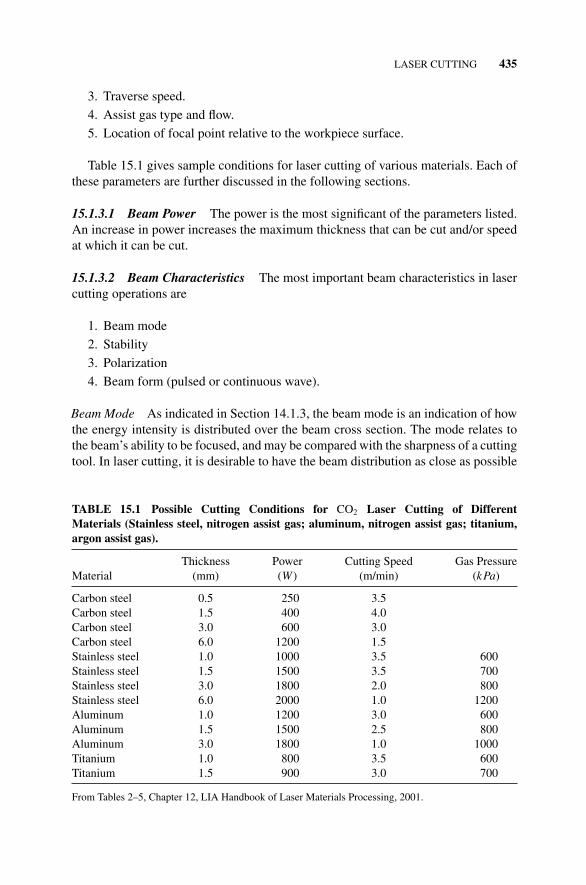
TABLE 15.1 Possible Cutting Conditions for CO2 Laser Cutting of DifferentMaterials (Stainless steel, nitrogen assist gas; aluminum, nitrogen assist gas; titanium,argon assist gas).
Thickness Power Cutting Speed Gas PressureMaterial (mm) (W) (m/min) (kPa)
From Tables 2–5, Chapter 12, LIA Handbook of Laser Materials Processing, 2001.
436 LASER CUTTING AND DRILLING
to the fundamental or Gaussian distributed TEM00 mode. This is the mode that canbe focused to the laser’s theoretically smallest possible focal size and thus the highestdensity for a given power. This reduces the kerf width, and increases cutting speedsand thickness of materials that can be cut. Since higher order or multimode beamsare more spread out, (Fig. 14.4), they result in larger focal spot sizes and thus lowerpower density for the same output power.
Beam Stability Stability of the beam is necessary to ensure that the beam power,mode, and direction (pointing stability) remain constant with time. An unstable beamaffects the tolerances and surface finish achievable with laser cutting. A stable beamthus reduces variations in product output and enhances quality. The stability ofthe beam is a characteristic of the laser generator, and depends on its design (seeSection 7.5).
Effect of Beam Polarization The basic concepts of polarization are discussed inSection 9.5. When the output of a laser beam is randomly polarized, it shows upin the quality of the cut workpiece as variations in kerf, edge smoothness, and per-pendicularity. This is mainly due to the impact of polarization on beam absorptionby the material. Absorption of the laser beam during cutting is determined using theFresnel relationships (see equations (16.3) and (16.7)), which indicate that the absorp-tion depends on both the angle of incidence and polarization. Experimental resultsindicate that in CO2 laser cutting, beams which are plane-polarized in a plane paral-lel to the cutting direction result in cutting speeds which can be up to 50% greaterthan those which are plane-polarized in the plane normal to the cutting direction.Generally, the circularly polarized beam results in higher cutting speeds at higherpower levels. For beams which are plane-polarized in the cutting plane, the beam isfound to be more effectively absorbed at angles of incidence greater than 80◦ and lessthan 90◦.
The cut quality varies with the orientation of the plane of polarization, and acircularly polarized beam generally results in better cut quality when the cuttingdirection changes. Thus, profile or contour cutting is preferably done using a circularlypolarized beam. The impact of the orientation of a linearly polarized beam on the cutquality is illustrated schematically in Fig. 15.3. As the figure shows, when the beamis polarized in the cutting direction, the resulting cut may have a narrow kerf withsharp, straight edges. However, as the plane of polarization is oriented away fromthe cutting direction, the energy absorption decreases, and as a result, the cuttingspeed is reduced, the kerf becomes wider, and the edges rougher and not square tothe material’s surface.
Beam Form Both pulsed and continuous wave (CW) beams can be used for lasercutting, with CW beams being more common.
For pulsed beams, the quality of cut is affected by the pulse duty, with the surfaceroughness decreasing with increasing pulse duty. The pulse duty is the ratio of thelength of time during which the laser beam is on in one cycle to the total length ofthe cycle time. In addition, the maximum cutting speeds that can be achieved are
LASER CUTTING 437
Plane of polarization
Kerfshape
Edgequality
AngledParallel Perpendicular
FIGURE 15.3 Effect of plane-polarized laser orientation on cut quality.
significantly reduced at low pulse rates (number of pulses per second). This is due tothe fact that at low pulse rates, there is enough time between pulses for the materialto substantially cool down. This helps extinguish the exothermic oxidation reaction,thereby reducing the overall process efficiency. Furthermore, as the material coolsdown between pulses at low pulse frequencies, there is a greater likelihood of formingdross (see Section 15.1.5.2). The resulting lower average temperature increases thesurface tension or viscosity of the molten material, making it more difficult to flowout of the reaction zone.
As discussed in Section 14.1.4, superpulsing and hyperpulsing can also be used toobtain significant improvements in process performance such as
1. Minimizing dross formation at the lower surface during cutting of some mate-rials.
2. Greater cut thickness (up to about 100%) to be achieved for the same averagepower as a CW output.
3. Increased processing speeds (20–33%) for the same average power as a CWoutput.
4. Making it easier to process highly reflective and/or high thermal conductivitymaterials.
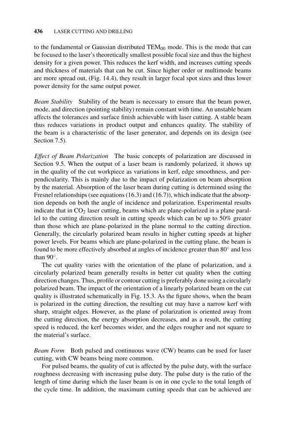
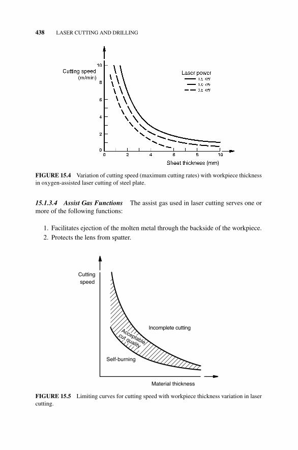
15.1.3.3 Traverse Speed The maximum speed that can be achieved for a givenlaser power decreases with increasing thickness of the workpiece (Fig. 15.4). For agiven power, a plot of the variation of cutting speed with thickness will generally havetwo limiting curves (Fig. 15.5). The upper curve indicates the maximum speed thatcan be achieved for a given thickness. Above this curve, cutting is incomplete. Belowthe lower curve, self-burning occurs. In other words, the material continues to burnwithout the aid of the laser. This often widens the kerf and produces a rough surface.
438 LASER CUTTING AND DRILLING
FIGURE 15.4 Variation of cutting speed (maximum cutting rates) with workpiece thicknessin oxygen-assisted laser cutting of steel plate.
15.1.3.4 Assist Gas Functions The assist gas used in laser cutting serves one ormore of the following functions:
1. Facilitates ejection of the molten metal through the backside of the workpiece.
2. Protects the lens from spatter.
Acceptablecut quality
Material thickness
Cuttingspeed
Incomplete cutting
Self-burning
FIGURE 15.5 Limiting curves for cutting speed with workpiece thickness variation in lasercutting.
LASER CUTTING 439
3. Acts as a heat source where it results in an exothermic reaction that aids incutting, such as may occur in oxygen-assisted cutting of steel.
Effect of Different Types of Assist Gases Common gases used include oxygen, inertgases, nitrogen, and air. Oxygen or air is used for exothermic reaction while cutting andtherefore they improve the cutting efficiency. Otherwise, an inert gas (usually argon)is used to assist in ejecting the molten metal without oxidation. In cases where theexothermic reaction is desired, the decision to use oxygen or air depends primarily oneconomics. Air is cheaper, but would require higher flow rates for the same amount ofthermal energy produced. Furthermore, air may introduce other gases such as nitrogeninto the cut surface, making it more brittle.
One setback of oxygen-assisted cutting is the deposition of an oxide layer onthe cut surface, giving it a dark appearance. Depending on the subsequent use ofthe cut parts, it may be necessary to clean off this oxide layer (by grinding or wirebrushing). The use of inert gases or nitrogen eliminates the formation of the oxidelayer. However, this may significantly reduce the cutting speeds that can be achieved.Furthermore, higher pressures are then necessary to reduce dross formation. Dross ismolten material that clings to and solidifies on the underside of the cut edge as burr(see Section 15.1.5.2).
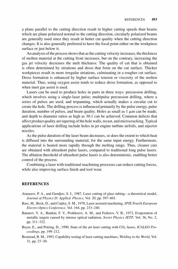
Small levels of impurity can cause significant deviations in cutting performance(such as a reduction in maximum cutting speed or increase in dross adhesion) com-pared to that of the pure gas, be it oxygen or inert gas. This is illustrated in Fig. 15.6,which shows a variation of the cutting speed for various levels of oxygen gas purity.This sensitivity to contamination is due to the build up of a boundary layer of the
6
5
3
0100 90
Oxygen purity (%)
Cutting speed(m/min)
4
2
1
92949698
FIGURE 15.6 Cutting speed as a function of oxygen gas purity. Mild steel of thickness2 mm, which is cut using 800 W at 2.5 bar pressure. (From ICALEO 1992 Proceedings, Vol.75. Copyright 1993, Laser Institute of America. All rights reserved).
440 LASER CUTTING AND DRILLING
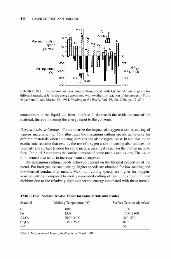
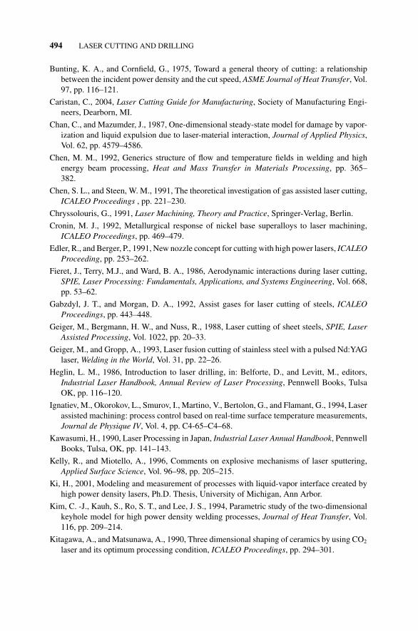
FIGURE 15.7 Comparison of maximum cutting speed with O2 and Ar assist gases fordifferent metals. �H◦ is the energy associated with exothermic reaction of the process. (FromMiyamoto, I., and Maruo, H., 1991, Welding in the World, Vol. 29, No. 9/10, pp. 12–23.)
contaminant at the liquid–cut front interface. It decreases the oxidation rate of thematerial, thereby lowering the energy input to the cut zone.
Oxygen-Assisted Cutting To summarize the impact of oxygen assist in cutting ofvarious materials, Fig. 15.7 illustrates the maximum cutting speeds achievable fordifferent materials when cut using inert gas and also oxygen assist. In addition to theexothermic reaction that results, the use of oxygen assist in cutting also reduces theviscosity and surface tension for some metals, making it easier for the molten metal toflow. Table 15.2 compares the surface tension of some metals and oxides. The oxidefilm formed also tends to increase beam absorption.
The maximum cutting speeds achieved depend on the thermal properties of themetal. For inert gas-assisted cutting, higher speeds are obtained for low-melting andlow-thermal conductivity metals. Maximum cutting speeds are higher for oxygen-assisted cutting, compared to inert gas-assisted cutting of titanium, zirconium, andniobium due to the relatively high exothermic energy associated with these metals.
TABLE 15.2 Surface Tension Values for Some Metals and Oxides
Material Melting Temperature (◦C) Surface Tension (dyne/cm)
Cu 1085 1350Fe 1538 1700–1800Al2O3 2050–2400 360–570Cr2O3 2350–2500 810FeO 580
Table 1, Miyamoto and Maruo, Welding in the World, 1991.
LASER CUTTING 441
However, the surface quality obtained is relatively poor. This is due to the fact that theoxidation region cannot be limited to the beam irradiating region as a result of the highexothermic energy. The relatively low cutting speeds achieved with aluminum andzinc is due to the high melting temperature of their oxides. The exothermic reactionassociated with steel is not very high, when compared to that of other metals such astitanium, zirconium, and niobium. Thus, the cutting speeds are not very high, but thequality of cut is relatively good since the relatively low exothermic reaction resultsin a reaction zone that is limited to the beam irradiated region.
Care must be used in oxygen-assisted cutting since excess oxygen may result inoverreaction or uncontrollable burning away from the main cutting direction, espe-cially for thick materials. That may increase striation formation, and thus, roughness.
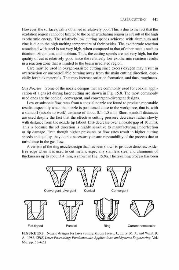
Gas Nozzles Some of the nozzle designs that are commonly used for coaxial appli-cation of a gas jet during laser cutting are shown in Fig. 15.8. The most commonlyused ones are the conical, convergent, and convergent–divergent designs.
Low or subsonic flow rates from a coaxial nozzle are found to produce repeatableresults, especially when the nozzle is positioned close to the workpiece, that is, witha standoff (nozzle to work) distance of about 0.1–1.5 mm. Short standoff distancesare used despite the fact that the effective cutting pressure decreases rather slowlywith distance from the nozzle tip (about 15% decrease over a nozzle gap of 10 mm).This is because the jet direction is highly sensitive to manufacturing imperfectionor tip damage. Even though higher pressures or flow rates result in higher cuttingspeeds and quality, they do not necessarily ensure repeatability of the process due toturbulence in the gas flow.
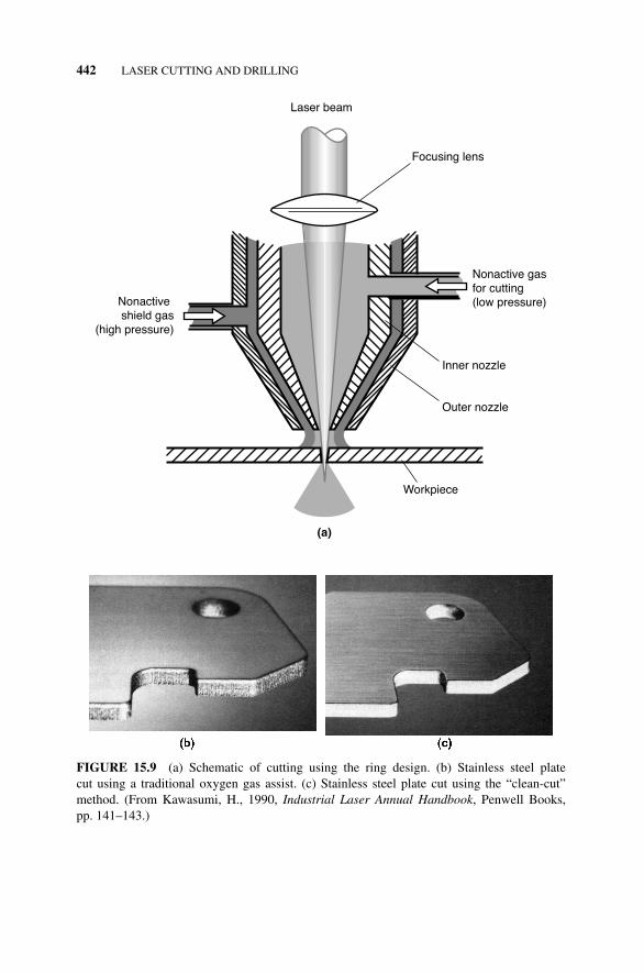
A version of the ring nozzle design that has been shown to produce drossles, oxide-free edge when it is used to cut metals, especially stainless steel and aluminum ofthicknesses up to about 3.4 mm, is shown in Fig. 15.9a. The resulting process has been
Parallel
Conical Convergent
Flat tipped
Convergent–divergent
Ring Current noncircular
FIGURE 15.8 Nozzle designs for laser cutting. (From Fieret, J., Terry, M. J., and Ward, B.A., 1986, SPIE, Laser Processing: Fundamentals, Applications, and Systems Engineering, Vol.668, pp. 53–62.)
442 LASER CUTTING AND DRILLING
Laser beam
Focusing lens
Inner nozzle
Outer nozzle
Nonactive gasfor cutting(low pressure)Nonactive
shield gas(high pressure)
Workpiece
(a)
FIGURE 15.9 (a) Schematic of cutting using the ring design. (b) Stainless steel platecut using a traditional oxygen gas assist. (c) Stainless steel plate cut using the “clean-cut”method. (From Kawasumi, H., 1990, Industrial Laser Annual Handbook, Penwell Books,pp. 141–143.)
LASER CUTTING 443
referred to as the “clean-cut” technique. The low-pressure (about 1 atm) nonoxidegases flowing through the inner nozzle protects the lens from the vapor plume, whilethe high-pressure (about 5 atm) nonoxide gases flowing through the outer nozzleremove viscous material. Figure 15.9b and c compare the cut quality obtained fora 2 mm thick stainless steel plate cut using a traditional oxygen gas assist and the“clean-cut” method.
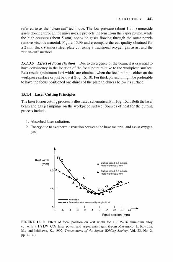
15.1.3.5 Effect of Focal Position Due to divergence of the beam, it is essential tohave consistency in the location of the focal point relative to the workpiece surface.Best results (minimum kerf width) are obtained when the focal point is either on theworkpiece surface or just below it (Fig. 15.10). For thick plates, it might be preferableto have the focus positioned one-thirds of the plate thickness below its surface.
15.1.4 Laser Cutting Principles
The laser fusion cutting process is illustrated schematically in Fig. 15.1. Both the laserbeam and gas jet impinge on the workpiece surface. Sources of heat for the cuttingprocess include
1. Absorbed laser radiation.
2. Energy due to exothermic reaction between the base material and assist oxygengas.
1.0
0-6 +4
Focal position (mm)
Kerf width(mm) Cutting speed: 0.5 m / mi n
Plate thickness: 3 mm
Cutting speed: 1.0 m / mi nPlate thickness: 2 mm
0.5
+3+2+10-1-2-3-4-5
Kerf widthBeam diameter measured by acrylic block
FIGURE 15.10 Effect of focal position on kerf width for a 7075-T6 aluminum alloycut with a 1.8 kW CO2 laser power and argon assist gas. (From Masumoto, I., Kutsuna,M., and Ichikawa, K., 1992, Transactions of the Japan Welding Society, Vol. 23, No. 2,pp. 7–14.)
444 LASER CUTTING AND DRILLING
The energy produced melts, and may partly evaporate material in front of the beam.The pressurized gas jet then ejects the molten material from the lower surface of theworkpiece. Material removal thus occurs by
1. Evaporation from the surface of the molten layer.
2. Ejection from the lower surface of the workpiece due to friction between thegas flow and the surface of the molten layer.
Energy is lost from the process by
1. Heat conduction.
2. Evaporation from the erosion front.
3. Melting of solid metal.
4. Ejection of the molten metal.
5. Reflection, radiation, and convection cooling by the gas flow. For subsonic gasflow, the convection cooling effect is found to be negligible.
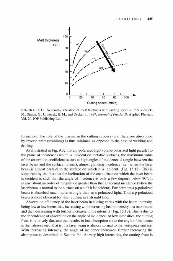
In the initial stages of the process, the entire beam and gas jet hit the workpiecesurface. However, once the process is initiated, a kerf is formed, and only a portionof the gas and laser beam impinge on the top surface of the workpiece directly aheadof the kerf, and that portion may be reflected back. The remaining portion of thebeam propagates downward into the kerf, and is partly absorbed at the front end ofthe kerf (erosion front), which is slightly inclined to the vertical. For a beam thatis linearly polarized in the cutting direction, most of the beam power is absorbed atthe erosion front. A thin layer of molten material forms at the interface between thekerf and the solid base material in front of it, and is ejected by the mechanisms listedearlier. The thickness of the melt increases with increasing cutting speed since moremolten metal is then produced per unit time. However, an increase in assist gas velocitydecreases the melt thickness since it results in a more rapid ejection of molten material(Fig. 15.11).
For a given laser power, the average temperatures attained in the molten layerdecrease as the thickness of the workpiece increases, until above a certain thickness,the average temperature falls below the melting temperature. This is the maximumthickness that can be cut with a laser of that power level, all other laser parametersbeing the same.
15.1.4.1 Beam Absorption During Laser Cutting Absorption of the laser beamduring cutting may be enhanced by a number of phenomena, including surface rough-ness, oxide formation, and plasma formation. Absorption may be by Fresnel absorp-tion or by inverse bremsstrahlung (see Section 16.3.2.1). However, since the directionof beam polarization strongly influences the cutting efficiency, this suggests that Fres-nel absorption is the principal mechanism. Since a significant portion of the energygenerated is removed with the ejected molten metal, temperatures in the cutting regionmay not be high enough to generate the high vapor densities essential for plasma
LASER CUTTING 445
80
60
00 100
Cutting speed (mm/s)
Melt thickness (μm)
40
20
80604020
60
100
170
300
100
Gas velocity (m
/s)
FIGURE 15.11 Schematic variation of melt thickness with cutting speed. (From Vicanek,M., Simon, G., Urbassek, H. M., and Decker, I., 1987, Journal of Physics D: Applied Physics,Vol. 20, IOP Publishing Ltd.)
formation. The role of the plasma in the cutting process (and therefore absorptionby inverse bremsstrahlung) is thus minimal, as opposed to the case of welding anddrilling.
As illustrated in Fig. 9.3c, for a p-polarized light (plane-polarized light parallel tothe plane of incidence) which is incident on metallic surfaces, the maximum valueof the absorption coefficient occurs at high angles of incidence, θ (angle between thelaser beam and the surface normal), almost glancing incidence (i.e., when the laserbeam is almost parallel to the surface on which it is incident) (Fig. 15.12). This issupported by the fact that the inclination of the cut surface on which the laser beamis incident is such that the angle of incidence is only a few degrees below 90◦. Itis also about an order of magnitude greater than that at normal incidence (when thelaser beam is normal to the surface on which it is incident). Furthermore a p-polarizedbeam is absorbed much more strongly than an s-polarized light. Thus a p-polarizedbeam is more efficient for laser cutting in a straight line.
Absorption efficiency of the laser beam in cutting varies with the beam intensity,being low at low intensities, increasing with increasing beam intensity to a maximum,and then decreasing with further increases in the intensity (Fig. 15.13). This is due tothe dependence of absorption on the angle of incidence. At low intensities, the cuttingfront is relatively flat, and that results in low absorption since the angle of incidenceis then almost zero, that is, the laser beam is almost normal to the workpiece surface.With increasing intensity, the angle of incidence increases, further increasing theabsorption as described in Section 9.4. At very high intensities, the cutting front is
446 LASER CUTTING AND DRILLING
Laser beam
Cuttingdirection
Workpiece
θ
≈ 1 °
≈ 3 °
FIGURE 15.12 Angle of incidence of laser beam on cut surface, and inclination of the cutsurface with the vertical.
0.5
0.3
00
Normalized mean intensity
Absorptionefficiency
0.1
1601208040
m = 0
FIGURE 15.13 Variation of absorption efficiency of a p-polarized beam with beam intensityfor a Gaussian beam (m = 0). (From Schulz, W., Simon, G., Urbassek, H. M., and Decker, I.,1987, Journal of Physics D: Applied Physics, Vol. 20, IOP Publishing Ltd.)
LASER CUTTING 447
1.0
0.9
0.8
0.7
0.6
0.5
0.3
0.1900
Angle of incidence (°)
ReflectivityR
0.2
0.4
6030
10,000 °KRS
RP
10,000 °K
100 °KRP
100 °KRS
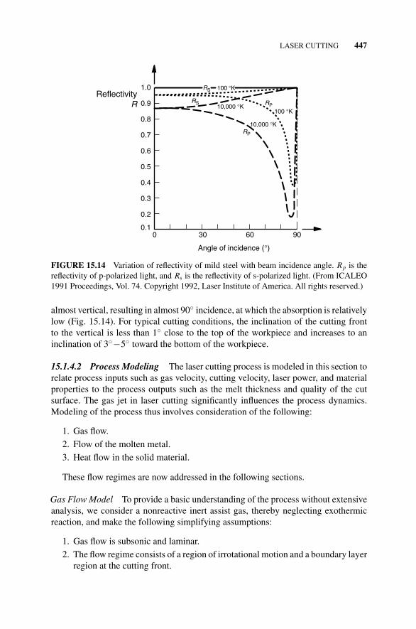
FIGURE 15.14 Variation of reflectivity of mild steel with beam incidence angle. Rp is thereflectivity of p-polarized light, and Rs is the reflectivity of s-polarized light. (From ICALEO1991 Proceedings, Vol. 74. Copyright 1992, Laser Institute of America. All rights reserved.)
almost vertical, resulting in almost 90◦ incidence, at which the absorption is relativelylow (Fig. 15.14). For typical cutting conditions, the inclination of the cutting frontto the vertical is less than 1◦ close to the top of the workpiece and increases to aninclination of 3◦−5◦ toward the bottom of the workpiece.
15.1.4.2 Process Modeling The laser cutting process is modeled in this section torelate process inputs such as gas velocity, cutting velocity, laser power, and materialproperties to the process outputs such as the melt thickness and quality of the cutsurface. The gas jet in laser cutting significantly influences the process dynamics.Modeling of the process thus involves consideration of the following:
1. Gas flow.
2. Flow of the molten metal.
3. Heat flow in the solid material.
These flow regimes are now addressed in the following sections.
Gas Flow Model To provide a basic understanding of the process without extensiveanalysis, we consider a nonreactive inert assist gas, thereby neglecting exothermicreaction, and make the following simplifying assumptions:
1. Gas flow is subsonic and laminar.
2. The flow regime consists of a region of irrotational motion and a boundary layerregion at the cutting front.
448 LASER CUTTING AND DRILLING
3. The cutting front is an inclined plane.
4. The flow only separates at the lower edge.
5. The gas stream is bounded by free streamlines. This is an oversimplificationsince the gas is surrounded to a large extent by air of almost the same density asthe gas. Turbulent mixing of the gas stream with the surrounding air increasesdownstream from the upper edge. Thus for relatively thick workpieces, theassumption will only hold for the upper portion of the cutting front.
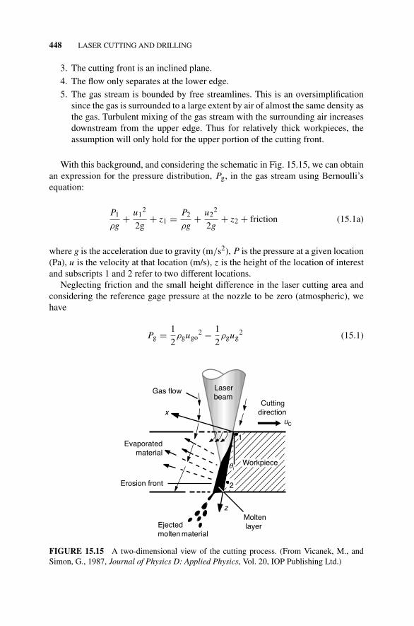
With this background, and considering the schematic in Fig. 15.15, we can obtainan expression for the pressure distribution, Pg, in the gas stream using Bernoulli’sequation:
P1
ρg+ u1
2
2g+ z1 = P2
ρg+ u2
2
2g+ z2 + friction (15.1a)
where g is the acceleration due to gravity (m/s2), P is the pressure at a given location(Pa), u is the velocity at that location (m/s), z is the height of the location of interestand subscripts 1 and 2 refer to two different locations.
Neglecting friction and the small height difference in the laser cutting area andconsidering the reference gage pressure at the nozzle to be zero (atmospheric), wehave
Pg = 1
2ρgugo
2 − 1
2ρgug
2 (15.1)
Laserbeam
Gas flow
Evaporatedmaterial
Ejectedmolten material
Cuttingdirection
Erosion front
Moltenlayer
Workpiece
x
z
uC
1
2
θi
FIGURE 15.15 A two-dimensional view of the cutting process. (From Vicanek, M., andSimon, G., 1987, Journal of Physics D: Applied Physics, Vol. 20, IOP Publishing Ltd.)
LASER CUTTING 449
where Pg is the pressure distribution in the gas stream, ug is the gas velocity distribu-tion, ugo is the gas velocity at the nozzle, and ρg is the room temperature gas density,which is assumed to be constant with pressure (i.e., incompressible).
The velocity distribution is needed to obtain the pressure distribution from equation(15.1).
For the shear stress distribution, we first consider the coordinate system shown inFig. 15.15 and then make the following assumptions:
1. Flow is Newtonian.
2. The thickness of the molten layer can be neglected.
Now considering the fact that the shear stress is proportional to the shear strainrate since flow is Newtonian, the shear stress distribution at the cutting front can beexpressed as
τ = μg∂ugz
∂x
∣∣∣x=0
(15.2)
The velocity field is obtained from the boundary layer equation:
ρg
(ugz
∂ugz
∂z+ ugx
∂ugz
∂x
)= −∂Pg
∂z+ ∂
∂x
(μg
∂ugz
∂x
)(15.3)
where μg is the gas viscosity (Pa s), τ is the shear stress distribution at the cuttingfront (N/m2), ugz is the gas velocity in the z-direction, and ugx is the gas velocity inthe x-direction.
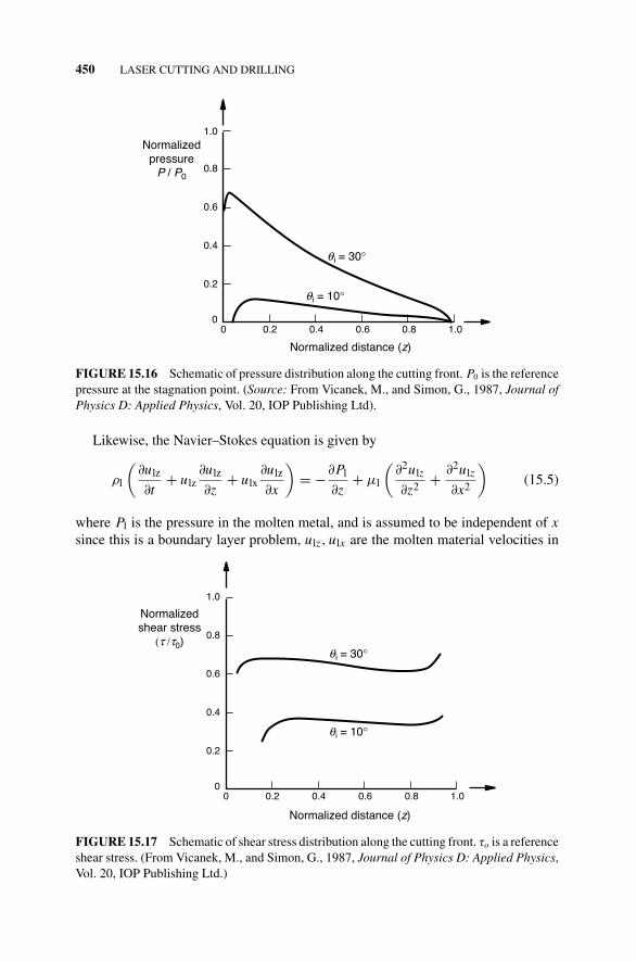
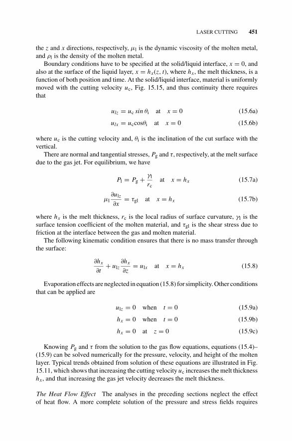
The pressure gradient in equation (15.3) is assumed to be known. The resultingpressure and shear stress distributions along the cutting front, obtained from equations(15.1)–(15.3) are of the form illustrated in Figs 15.16 and 15.17, respectively. Thepressure distribution has a peak just below the upper edge of the cutting front, andthen reduces monotonically to zero at the lower edge. The pressure also increaseswith increasing inclination (θi) of the cutting front from the vertical. The smaller thecutting front slope, the lower the resistance to flow, and thus the smaller the pressure.The shear stress, however, remains relatively constant over most of the cutting front,and is less sensitive to the inclination.
Modeling the Melt Flow Since most of the molten material is forcibly ejected bythe gas jet, only a thin layer of melt remains on the cutting front, with a thicknessof the order of 40 �m. Thus, flow may be assumed, with a reasonable degree ofaccuracy, to be two dimensional. In other words, this is a boundary layer problem.Using the coordinate system shown in Fig. 15.15 and assuming incompressible flow,the continuity equation can be expressed as
∂ulz
∂z+ ∂ulx
∂x= 0 (15.4)
450 LASER CUTTING AND DRILLING
0.8
0.6
0.4
0.2
00 0.2 0.6 0.8
Normalized distance (z)
Normalizedpressure
P / P0
0.4
θ i = 30°
θ i = 10°
1.0
1.0
FIGURE 15.16 Schematic of pressure distribution along the cutting front. P0 is the referencepressure at the stagnation point. (Source: From Vicanek, M., and Simon, G., 1987, Journal ofPhysics D: Applied Physics, Vol. 20, IOP Publishing Ltd).
Likewise, the Navier–Stokes equation is given by
ρl
(∂ulz
∂t+ ulz
∂ulz
∂z+ ulx
∂ulz
∂x
)= −∂Pl
∂z+ μl
(∂2ulz
∂z2 + ∂2ulz
∂x2
)(15.5)
where Pl is the pressure in the molten metal, and is assumed to be independent of x
since this is a boundary layer problem, ulz, ulx are the molten material velocities in
1.0
0.8
0.6
0.4
0.2
00 0.2 0.6 0.8
Normalized distance (z)
Normalizedshear stress
(τ /τ0)
0.4
θ i = 30°
θ i = 10°
1.0
FIGURE 15.17 Schematic of shear stress distribution along the cutting front. τo is a referenceshear stress. (From Vicanek, M., and Simon, G., 1987, Journal of Physics D: Applied Physics,Vol. 20, IOP Publishing Ltd.)
LASER CUTTING 451
the z and x directions, respectively, μl is the dynamic viscosity of the molten metal,and ρl is the density of the molten metal.
Boundary conditions have to be specified at the solid/liquid interface, x = 0, andalso at the surface of the liquid layer, x = hx(z, t), where hx, the melt thickness, is afunction of both position and time. At the solid/liquid interface, material is uniformlymoved with the cutting velocity uc, Fig. 15.15, and thus continuity there requiresthat
ulz = uc sin θi at x = 0 (15.6a)
ulx = uccosθi at x = 0 (15.6b)
where uc is the cutting velocity and, θi is the inclination of the cut surface with thevertical.
There are normal and tangential stresses, Pg and τ, respectively, at the melt surfacedue to the gas jet. For equilibrium, we have
Pl = Pg + γl
rcat x = hx (15.7a)
μl∂ulz
∂x= τgl at x = hx (15.7b)
where hx is the melt thickness, rc is the local radius of surface curvature, γl is thesurface tension coefficient of the molten material, and τgl is the shear stress due tofriction at the interface between the gas and molten material.
The following kinematic condition ensures that there is no mass transfer throughthe surface:
∂hx
∂t+ ulz
∂hx
∂z= ulx at x = hx (15.8)
Evaporation effects are neglected in equation (15.8) for simplicity. Other conditionsthat can be applied are
ulz = 0 when t = 0 (15.9a)
hx = 0 when t = 0 (15.9b)
hx = 0 at z = 0 (15.9c)
Knowing Pg and τ from the solution to the gas flow equations, equations (15.4)–(15.9) can be solved numerically for the pressure, velocity, and height of the moltenlayer. Typical trends obtained from solution of these equations are illustrated in Fig.15.11, which shows that increasing the cutting velocity uc increases the melt thicknesshx, and that increasing the gas jet velocity decreases the melt thickness.
The Heat Flow Effect The analyses in the preceding sections neglect the effectof heat flow. A more complete solution of the pressure and stress fields requires
452 LASER CUTTING AND DRILLING
consideration of the thermal effect. The governing equation for heat flow is given byequation (10.2) as
ρcp
dT
dt= ∂
∂x
(k∂T
∂x
)+ ∂
∂y
(k∂T
∂y
)+ ∂
∂z
(k∂T
∂z
)+ qs (10.2a)
In Chapter 10, this equation was first simplified by neglecting the internal energygeneration term, qs. The resulting equations associated with the line heat sourcemodel, equations (10.16), (10.18), and (10.21), for the temperature distribution, peaktemperatures, and cooling rates, are still applicable as initial approximations for con-duction heat flow in the workpiece when an inert gas or nitrogen is used as theassist gas. When oxygen or air is used as the assist gas, however, qs cannot beneglected, as the exothermic reaction is then significant enough to influence theresulting temperatures.
For a more accurate analysis, however, the continuity equation, Navier–Stokesequation, and the thermal equation will have to be solved numerically, with theappropriate boundary conditions for the gas flow, melt flow, and solid workpieceregimes.
Example 15.1 A 2.5 mm thick aluminum plate is cut using a 1.5 kW laser. If theresulting kerf width is 0.3 mm; the ambient temperature is 25◦C; and 5% of theincident laser beam is absorbed by the plate, determine the cutting speed. You mayassume that there is no vaporization, and that there are no energy losses by conduction,convection, or radiation.
Solution:
We apply the discussion in Chapter 10 to this problem. The material properties areobtained from Appendices 10D and 10E as
Average density, ρ = 2700 kg/m3
Average specific Heat, c = 900 J/kgK
Latent heat of fusion, L = 397 kJ/kg
Melting temperature, Tm = 660.4◦ C
From equation (10.1), we have
Qa = q × t = macp�Tm + maLm + macp�Tv + maLv + Ql
where q is the power supplied, and t is the cutting time. Since it is assumed that thereis no vaporization, and that there are no energy losses by conduction, convection, orradiation, we have
q × t = macp�Tm + maLm = ρV (cp�Tm + Lm)
LASER CUTTING 453
or
q × t = ρ × l × wk × h(cp�Tm + Lm)
where l is the length of the cut that is made, wk is the kerf width, and h is the platethickness. Thus the average cutting speed, uc, is
The major factors that determine the quality of the cut part are the surface striations,dross formation, and cracking. In the following sections, we discuss the mechanismsof striation and dross formation. Cracking is discussed in relation to specific materialsin Section 15.1.6, and also more extensively in Section 11.2.2.
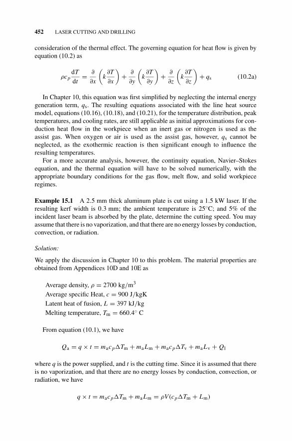
15.1.5.1 Striations of the Cut Surface The surfaces cut using a laser beam nor-mally have a nearly periodic striation pattern, Fig. 15.18a, that results in a surfaceroughness that may also vary in the thickness direction (Fig. 15.18b), depending onthe processing conditions.
FIGURE 15.18 Illustration of striations formed on a surface after laser cutting. (a) Periodicnature of the striation pattern. (b) Variation of striation pattern in the thickness direction forrelatively thick materials. (From (a)LIA Handbook of Laser Materials Processing, 2001, LaserInstitute of America, Orlando, FL; (b) Powell, J., Frass, K., Menzies, I. A., and Fuhr, H., 1988,SPIE, High Power CO2 Laser Systems and Applications, Vol. 1020, pp. 156–163.)
454 LASER CUTTING AND DRILLING
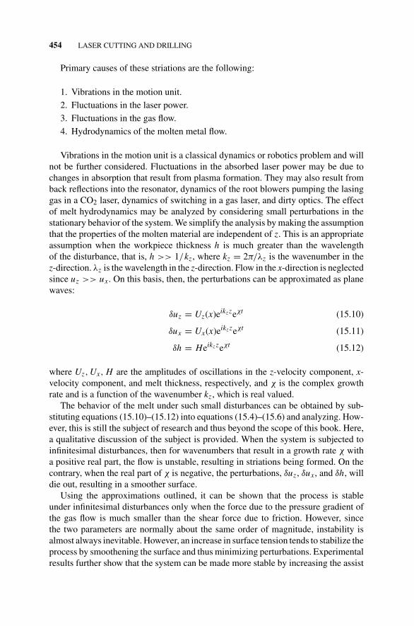
Primary causes of these striations are the following:
1. Vibrations in the motion unit.
2. Fluctuations in the laser power.
3. Fluctuations in the gas flow.
4. Hydrodynamics of the molten metal flow.
Vibrations in the motion unit is a classical dynamics or robotics problem and willnot be further considered. Fluctuations in the absorbed laser power may be due tochanges in absorption that result from plasma formation. They may also result fromback reflections into the resonator, dynamics of the root blowers pumping the lasinggas in a CO2 laser, dynamics of switching in a gas laser, and dirty optics. The effectof melt hydrodynamics may be analyzed by considering small perturbations in thestationary behavior of the system. We simplify the analysis by making the assumptionthat the properties of the molten material are independent of z. This is an appropriateassumption when the workpiece thickness h is much greater than the wavelengthof the disturbance, that is, h >> 1/kz, where kz = 2π/λz is the wavenumber in thez-direction. λz is the wavelength in the z-direction. Flow in the x-direction is neglectedsince uz >> ux. On this basis, then, the perturbations can be approximated as planewaves:
δuz = Uz(x)eikzzeχt (15.10)
δux = Ux(x)eikzzeχt (15.11)
δh = Heikzzeχt (15.12)
where Uz, Ux, H are the amplitudes of oscillations in the z-velocity component, x-velocity component, and melt thickness, respectively, and χ is the complex growthrate and is a function of the wavenumber kz, which is real valued.
The behavior of the melt under such small disturbances can be obtained by sub-stituting equations (15.10)–(15.12) into equations (15.4)–(15.6) and analyzing. How-ever, this is still the subject of research and thus beyond the scope of this book. Here,a qualitative discussion of the subject is provided. When the system is subjected toinfinitesimal disturbances, then for wavenumbers that result in a growth rate χ witha positive real part, the flow is unstable, resulting in striations being formed. On thecontrary, when the real part of χ is negative, the perturbations, δuz, δux, and δh, willdie out, resulting in a smoother surface.
Using the approximations outlined, it can be shown that the process is stableunder infinitesimal disturbances only when the force due to the pressure gradient ofthe gas flow is much smaller than the shear force due to friction. However, sincethe two parameters are normally about the same order of magnitude, instability isalmost always inevitable. However, an increase in surface tension tends to stabilize theprocess by smoothening the surface and thus minimizing perturbations. Experimentalresults further show that the system can be made more stable by increasing the assist
LASER CUTTING 455
gas velocity or decreasing the cutting velocity when the cutting velocity is high. Onthe contraly, at low cutting velocities, an increase in the assist gas velocity or decreasein cutting velocity makes the system less stable.
A unique aspect of the striations is the two distinct patterns evident on the surface(Fig. 15.15). One pattern is closer to the upper surface of the workpiece, with relativelyfine striations. The other pattern is on the lower portion of the cut surface, withrelatively coarse striations. The two patterns are separated by a distinct line that isalmost parallel to the workpiece surface. The two striation patterns result from thetemperature distribution in the molten layer in the vertical direction, being higherin the upper portion compared to the lower portion. The speed of the assist gasas it enters the kerf is generally subsonic. However, its temperature increases as itpenetrates deeper into the kerf, resulting in a decrease in the gas density. In a sense,then, the cut acts as a converging nozzle, increasing the gas flow velocity. When theflow reaches sonic velocities, it becomes turbulent and thus changes the dynamicsof the molten layer. The turbulence in the gas flow also cools the molten layer moreeffectively, and since the oscillation frequency of the molten layer when subjected toperturbations is higher for higher temperatures, the frequency of the striation patternis lower for the lower portion of the cut surface. The characteristic frequencies ofthe oscillations depend on the workpiece thickness, and may be of the order of 103
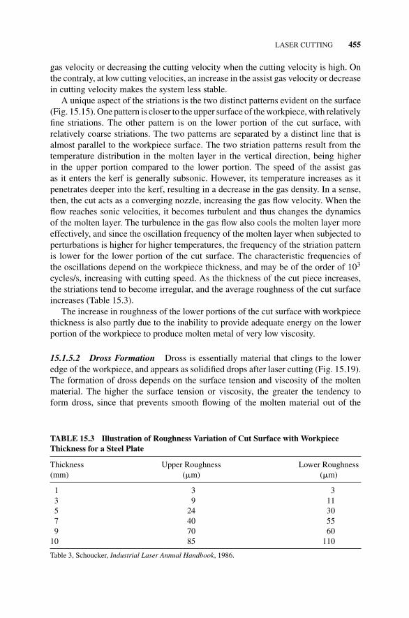
cycles/s, increasing with cutting speed. As the thickness of the cut piece increases,the striations tend to become irregular, and the average roughness of the cut surfaceincreases (Table 15.3).
The increase in roughness of the lower portions of the cut surface with workpiecethickness is also partly due to the inability to provide adequate energy on the lowerportion of the workpiece to produce molten metal of very low viscosity.
15.1.5.2 Dross Formation Dross is essentially material that clings to the loweredge of the workpiece, and appears as solidified drops after laser cutting (Fig. 15.19).The formation of dross depends on the surface tension and viscosity of the moltenmaterial. The higher the surface tension or viscosity, the greater the tendency toform dross, since that prevents smooth flowing of the molten material out of the
TABLE 15.3 Illustration of Roughness Variation of Cut Surface with WorkpieceThickness for a Steel Plate
FIGURE 15.19 Dross formed on the lower edge of the workpiece after laser cutting.(a) Photograph of dross. (b) Schematic of dross. (From Powell, J., Frass, K., Menzies, I.A., and Fuhr, H., 1988a, SPIE, High Power CO2 Laser Systems and Applications, Vol. 1020,pp. 156–163.)
reaction zone. Inert gas-assisted cutting has a greater tendency to form dross as com-pared to oxygen-assisted cutting of the same material since the surface tension of thepure metal is generally greater than that of its oxide. Thus, higher pressures (over 1MPa or 10 bars) are required to achieve dross-free cutting with inert gas assist thanwith oxygen assist. Furthermore, the dross formed during inert gas assisted cuttingis usually more difficult to remove than the more brittle oxide dross formed whenoxygen assist is used.
15.1.6 Material Considerations
The effectiveness of a laser in processing a given material depends on the propertiesof the material, for example, absorptivity (1 - reflectance) at that wavelength, thermalconductivity, melting and boiling points, heat of reaction, and surface tension of themolten material. The reflectance, thermal, and physical properties of some commonmetals are summarized in Appendices 10D–10F. In the following sections, we shallconsider the behavior of both metals and nonmetals when cut with a laser.
LASER CUTTING 457
15.1.6.1 Metals
Plain Carbon Steels Oxygen-assisted cutting is normally used for carbon steelswhere the exothermic reaction between oxygen and iron aids in the cutting process,resulting in cutting speeds, which are much higher than those achieved when inertgas is used. The exothermic reaction is given by the following equation:
Fe + 1
2O2 = FeO + Energy (258 kJ/mol) at 2000 K (15.13)
2Fe + 3
2O2 = Fe2O3 + Energy (827 kJ/mol) at 2000 K (15.14)
Oxygen-assisted cutting also helps reduce dross formation, since the viscosity ofthe molten metal decreases when oxidized, making it easier to be removed by thegas jet. The presence of phosphorus and sulfur in the carbon steel can cause burnoutalong the cut edge. An increase in carbon content of the steel tends to improve theedge quality, but with a greater tendency for cracking in the heat-affected zone (seeSection 11.2.2).
Galvanized Steel Laser cutting of galvanized steel often results in rough edges withextensive dross. This is most likely due to the formation of zinc oxide which doesnot flow easily. To obtain reasonable quality, lower cutting speeds are normally used,compared to the speeds used for uncoated steels.
Stainless Steels The small heat-affected zone associated with laser cutting minimizesany impact that the cutting process may have on its corrosion resistance. In usingoxygen assist, the heat of reaction that results is not as significant as that associatedwith plain carbon steels. Thus the cutting speeds achieved for stainless steels arerelatively lower than those for carbon steels. As a result, oxygen assist is normallynot recommended for cutting of stainless steels, especially since the burning causedby the assist gas may be detrimental to the cut quality. Ferritic and martensitic stainlesssteels tend to produce clean and smooth-edged cuts, while austenitic stainless steelstend to have dross sticking out from the lower surface of the workpiece. This isprimarily due to the high viscosity of molten nickel.
Alloy and Tool Steels The edges produced in laser cutting of high alloy steels such asAISI 4340 steel are often clean and square. This is essentially due to the more precisecontrol of the alloying element contents of such materials. Likewise, a number oftool steels are also good candidates for laser cutting. However, the tungsten-basedtool steels, Groups T and H, retain a lot of heat in the molten state, resulting in oftenburned out cuts.
Aluminum and Its Alloys Aluminum and its alloys are highly reflective (up to 97%)of the high 10.6 �m CO2 laser beam wavelength. This, coupled with their relativelyhigh thermal conductivity (≈ 247 W/m K), makes it difficult to initiate cutting in
458 LASER CUTTING AND DRILLING
aluminum alloys. High beam intensities, achieved using either superpulsing or hy-perpulsing (Sections 14.1.4 and “Beam Form”), are thus necessary to cut aluminumalloys. Absorption of the laser beam at the top surface can be enhanced by usingany of the coating techniques discussed in Section 17.1.2.3, but anodizing aluminumhas been found to be effective. This is done by coating the base material with a thinlayer (approximately 20 �m) of Al2O3. Al2O3 is highly absorptive (≈100%) of theinfrared CO2 laser beam at thicknesses greater than 5 �m. Absorptivity can also beimproved by graphite coating.
Aluminum undergoes a highly exothermic reaction with oxygen as
4Al + 3O2 = 2Al2O3 + Energy (1670 kJ/mol) at 293 K (15.15)
which can increase cutting speeds to some extent. However, the exothermic reaction isnot as effective in increasing the cutting speeds for the same amount of released energyas compared to the case of iron. This is because the resulting oxide layer, aluminumoxide (Al2O3), reduces the diffusion of atoms to the reaction front, thereby reducingthe oxidation rate. The oxide layer is periodically disrupted during the cutting processby the pressurized oxygen jet, permitting some amount of oxidation to occur. Thefunction of assist gas in cutting these materials is thus primarily to eject the moltenmetal. As a result, oxygen assist is normally not recommended for cutting aluminum.
Dross formation can be a problem in cutting aluminum. This is because the highthermal conductivity of the base material results in a low temperature melt. Thisresults in the surface tension of the molten layer being relatively high, and thus moredifficult to eject, leaving dross at the bottom edge of the cut. The dross formed is easilyremoved by mechanical means, though. The high thermal conductivity of the basematerial may sometimes lead to overheating of small components during cutting. This,combined with the low melting temperature, may even result in widescale melting.This can be prevented by spraying either water or soluble oil on the component duringcutting. The water is kept away by the pressure of the gas jet, and cools the componentby evaporation.
Laser cutting sometimes produces intergranular cracks (cracks that preferentiallypropagate along grain boundaries) on the surface of some aluminum alloys, makingthem unsuitable for aircraft structural components.
Copper and Its Alloys Both the conductivity (≈ 398 W/m K) and reflectivity (up to98.4%) of copper are higher than those of aluminum, making it even more difficultto process with a CO2 laser. Even though the exothermic reaction associated with theprocess can increase the cutting speeds, the energy released is relatively small:
2Cu + 1
2O2 = Cu2O + Energy (167 kJ/mol) at 293 K (15.16)
Cu + 1
2O2 = CuO + Energy (155 kJ/mol) at 293 K (15.17)
LASER CUTTING 459
Any increase in cutting speed is primarily due to increased absorption that resultsfrom the formation of the highly absorptive oxide layer in the vicinity of the cut.
A number of copper alloys such as brass and bronze are more effectively processeddue to a reduced reflectivity and thermal conduction.
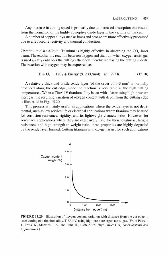
Titanium and Its Alloys Titanium is highly effective in absorbing the CO2 laserbeam. The exothermic reaction between oxygen and titanium when oxygen assist gasis used greatly enhances the cutting efficiency, thereby increasing the cutting speeds.The reaction with oxygen may be expressed as
Ti + O2 = TiO2 + Energy (912 kJ/mol) at 293 K (15.18)
A relatively thick and brittle oxide layer (of the order of 1–3 mm) is normallyproduced along the cut edge, since the reaction is very rapid at the high cuttingtemperatures. When a Ti6Al4V titanium alloy is cut with a laser using high-pressureinert gas, the resulting variation of oxygen content with depth from the cutting edgeis illustrated in Fig. 15.20.
This process is mainly useful in applications where the oxide layer is not detri-mental, such as low service life or electrical applications where titanium may be usedfor corrosion resistance, rigidity, and its lightweight characteristics. However, foraerospace applications where they are extensively used for their toughness, fatigueresistance, and high strength-to-weight ratio, these properties are highly degradedby the oxide layer formed. Cutting titanium with oxygen assist for such applications
4.0
3.0
2.0
1.0
00 100 200 300
Distance from edge (nm)
Oxygen contentweight (%)
FIGURE 15.20 Illustration of oxygen content variation with distance from the cut edge inlaser cutting of a titanium alloy, Ti6Al4V, using high-pressure argon assist gas. (From Powell,J., Frass, K., Menzies, I. A., and Fuhr, H., 1988, SPIE, High Power CO2 Laser Systems andApplications.)
460 LASER CUTTING AND DRILLING
is therefore undesirable. Thus, it may be preferable to use an inert gas assist whencutting titanium alloys for aerospace applications, but at a reduced cutting rate whichmay be an order of magnitude lower than that attainable when using oxygen assist.However, there is a tendency for dross to form on the underside of the cut edge undersuch circumstances. As an example, high cutting speeds of about 3.6 m/min can beobtained in cutting a 6.4 mm thick plate with 500 W power using oxygen assist.
Nickel and its Alloys Pure nickel has a relatively low thermal conductivity (≈59 W/mK) and reflectivity (up to 94%) compared to those of copper and aluminum,making it easier to cut using lasers. The use of oxygen assist does improve cuttingspeeds as a result of the exothermic reaction:
Ni + 1
2O2 = NiO + Energy (244 kJ/mol) at 293 K (15.19)
This is more effective when cutting Ni–Fe alloys. Some nickel alloys, however,have reflectivities and conductivities that make them more difficult to process withlasers. Furthermore, the high viscosity of molten nickel results in dross formation.
Despite the relative ease with which a number of nickel alloys can be processedwith a laser, the metallurgical effects of the process, even in the small heat affectedzone, precludes its use in some aerospace applications such as jet engines where theworking environment can be aggressive.
15.1.6.2 Nonmetals
Polymers In cutting polymers, the intense laser beam tends to break down the poly-mer chains. Edges produced in cutting thermoplastics appear polished as a result ofresolidified melting. As the strength of the polymer increases, there is a tendency forcharring to occur along the cut edge, since more energy is then required to break downthe bonds. Polyester and polycarbonate are relatively easier to cut, while with PVC(polyvinyl chloride), phenolic, and polyimide, a significant amount of decomposedmaterial may be found along the cut edge. Care must always be taken to contain haz-ardous and/or corrosive fumes that may be generated in the processing of polymers.It is generally preferable to use air rather than oxygen in cutting polymeric materials.
Both natural and synthetic rubber are effectively cut in thicknesses up to 19 mmusing lasers, and they tend to exhibit slight stickiness along the edge when freshlycut.
Composites Since composites consist of different materials, the cutting conditionsare determined by only one of the component materials, which may result in degra-dation of the other materials during cutting. One approach to this problem is to cutat higher speeds using higher power lasers. Thin sheets (say, less than 0.5 mm) oflaminated composites with a polymeric material as the matrix can be trimmed usinglasers before they are cured. Thicker sections or fully cured composites often result incharring, delamination, and thermal damage along the cut edge. When the properties
LASER CUTTING 461
of the constituent materials are similar, the composite material is then easier to pro-cess using a laser. In all cases, care must also be exercised in containing hazardousfumes and material.
Quartz and Glass The relatively low coefficient of expansion of quartz makes iteasier to cut in comparison to glass. The high coefficient of thermal expansion ofglass results in thermal shock that tends to form edge cracks.
One approach to cutting such brittle materials is by first laser scribing to removea small amount of material from the surface of the glass, and then applying force byflexing, to fracture the material along the line of scribing. This requires only a smallpower density, resulting in a very small heat-affected zone size. Another approachinvolves controlled thermal fracture, which takes advantage of the localized thermalstresses that are set up due to the high coefficient of thermal expansion and high beamintensity to fracture the material. The process is quite controllable, with the fractureessentially following the path of the beam.
Ceramics The high transverse temperature gradients associated with laser processingcan generate relatively high thermal stresses that cause cracking in ceramic materials,which are inherently brittle. Furthermore, the thermal conductivity decreases rapidlywith increasing temperature in such materials, significantly reducing thermal diffu-sion into the body of the workpiece. Preheating the workpiece to a relatively hightemperature before cutting, or preheating the region directly ahead of the laser beamreduces the transverse temperature gradient, and thus the tendency to crack.
Cutting of alumina often results in cracking. Cracks also develop during cutting ofsilicon carbide of thickness greater than 3 mm. Silicon nitride, on the other hand, canbe cut to 4 mm thickness at about 10 mm/s. The surface roughness obtained whenzirconia is cut is about 10 �m, while silicon nitride results in a surface roughness ofabout 100 �m.
Textiles and Fabrics Lasers are also used in the textile industry to cut fabric. Toincrease productivity, several layers of fabric may be stacked up and cut at the sametime. However, this causes the edges of the individual layers to become welded to-gether. This may be prevented by pressing the layers together to prevent the cuttinggas from entering sideways between them.
Wood Wood can generally be cut using CO2 lasers. The cutting rate tends to increaseas the wood’s density and moisture content decreases, but appears to be independentof the grain direction. One problem that is often encountered is charring of the cutedge during cutting. However, the extent of charring is usually very small, of the orderof microns in depth, and reduces with increasing cutting speed.
Paper and Cardboard Laser cutting of paper and cardboard has an advantage overconventional cutting since it does not result in broken fibers which may remain at-tached to the paper and interfere with printing.
462 LASER CUTTING AND DRILLING
Example 15.2 A 1.0 kW CO2 laser is used to cut a 4.5 mm thick titanium alloy plateusing an inert gas assist. The resulting cutting speed and kerf width are 3.0 m/minand 400 �m, respectively.
(a) Calculate the surface temperature at a point 4.0 mm behind the laser beamand 3.5 mm to one side, if the heat transfer efficiency is 90%, and the ambienttemperature is 25◦C.
(b) Estimate the size of the heat-affected zone for this process if a cold rolled alloyrecrystallizes at a temperature equal to half the absolute melting temperatureof pure titanium.
(c) Obtain the surface temperature for the point in (a) if oxygen assist was used,and 50% of the exothermic reaction contributed to the cutting process.
Solution:
Again, we apply the discussion in Chapter 10 to this problem. The material properties(approximated to be the same as for pure titanium) are obtained from Appendices10D and 10E as
Average density, ρ = 4507 kg/m3 = 4.507 × 10⁻⁶kg/mm3
Average specific heat, cp = 99.3 J/kg K
Thermal conductivity, k = 11.4 W/m K = 0.0114 W/mm K.
Melting temperature, Tm = 1668◦C = 1941 K.
Other data
Atomic weight of titanium is 47.9 g/mol
Cutting speed is 3.0 m/min = 50 mm/s
The amount of material, Mt , removed per unit time is
Now the laser power, q1, available at the workpiece is
q1 = 1000 × 0.9 = 900 W
When oxygen assist is used, additional heat available from the exothermic reaction(see equation (15.18)) is
q2 = 0.5 × 912 kJ/mol = 0.5 × 912 × 103
47.9× 0.405 J/s = 3855.5 W
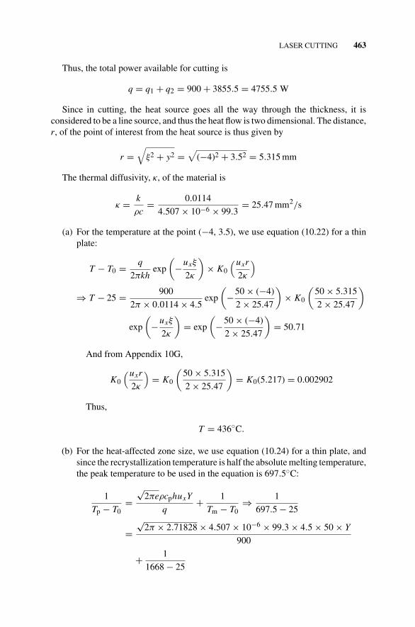
LASER CUTTING 463
Thus, the total power available for cutting is
q = q1 + q2 = 900 + 3855.5 = 4755.5 W
Since in cutting, the heat source goes all the way through the thickness, it isconsidered to be a line source, and thus the heat flow is two dimensional. The distance,r, of the point of interest from the heat source is thus given by
r =√
ξ2 + y2 =√
(−4)2 + 3.52 = 5.315 mm
The thermal diffusivity, κ, of the material is
κ = k
ρc= 0.0114
4.507 × 10−6 × 99.3= 25.47 mm2/s
(a) For the temperature at the point (−4, 3.5), we use equation (10.22) for a thinplate:
T − T0 = q
2πkhexp
(−uxξ
2κ
)× K0
(uxr
2κ
)
⇒ T − 25 = 900
2π × 0.0114 × 4.5exp
(−50 × (−4)
2 × 25.47
)× K0
(50 × 5.315
2 × 25.47
)
exp
(−uxξ
2κ
)= exp
(−50 × (−4)
2 × 25.47
)= 50.71
And from Appendix 10G,
K0
(uxr
2κ
)= K0
(50 × 5.315
2 × 25.47
)= K0(5.217) = 0.002902
Thus,
T = 436◦C.
(b) For the heat-affected zone size, we use equation (10.24) for a thin plate, andsince the recrystallization temperature is half the absolute melting temperature,the peak temperature to be used in the equation is 697.5◦C:
1
Tp − T0=
√2πeρcphuxY
q+ 1
Tm − T0⇒ 1
697.5 − 25
=√
2π × 2.71828 × 4.507 × 10−6 × 99.3 × 4.5 × 50 × Y
900
+ 1
1668 − 25
464 LASER CUTTING AND DRILLING
And the heat-affected zone size is
Y = 1.9 mm.
(c) The heat input is now 4755.5 kW. Thus,
⇒ T − 25 = 4755.5
2π × 0.0114 × 4.5exp
(−50 × (−4)
2 × 25.47
)× K0
(50 × 5.315
2 × 25.47
)
or
T = 2196◦C.
This is higher than the melting point of titanium. That means the kerf widthwill be greater than 7 mm.
15.1.7 Advantages and Disadvantages of Laser Cutting
15.1.7.1 Advantages The general advantages of laser cutting in comparison withconventional cutting processes such as plasma arc cutting, electrical discharge ma-chining, oxyacetylene flame cutting, and mechanical cutting are the following:
1. It results in a narrow kerf width, thereby reducing waste. The reduced kerf widthalso makes the production of arbitrary contours more feasible.
2. Relatively high cutting speeds.
3. Small heat-affected zone due to the relatively small total heat input. Thus, thereis very little damage to the base material, making it suitable for heat sensitiveand burnable materials. There is also very little residual stress and distortion.
4. It is a noncontact process, and thus there is no tool wear and no mechanicalforces that could damage delicate workpieces. The lack of mechanical forcesalso implies less complex fixtures to hold the workpiece in place.
5. Good for both very soft (highly deformable) materials such as paper and veryhard (difficult to cut) materials such as diamond.
6. High degree of flexibility (which may facilitate the cutting of complex geome-tries) and low level of noise.
7. It results in cut edges that are square, and not rounded, as occurs in many otherthermal cutting methods.
15.1.7.2 Disadvantages The principal disadvantages of laser cutting are thefollowing:
1. Highly reflective and conductive materials such as gold and silver are difficultto cut using lasers. Methods for improving the absorptivity of metals in generalfor the laser beam are discussed in Section 17.1.2.3, while those for facilitating
LASER CUTTING 465
cutting in highly reflective materials are discussed in Sections 14.1.4 and “BeanForm”.
2. The melting and rapid quenching associated with the process result in a hardedge of the cut piece for hardenable materials.
3. Laser cutting has traditionally been limited to cutting thin materials, that is,less than a few millimeters thick. Furthermore, it is generally limited to cuttingthrough the materials. Thus blind slots, pockets, or holes are difficult to cutaccurately using a laser.
4. The initial capital cost of a laser cutting system is relatively high, about twoorders of magnitude higher than that of an oxy-fuel system.
5. Processing of certain materials (such as polymers) may result in the productionof dangerous exhaust fumes.
15.1.8 Specific Comparison with Conventional Processes
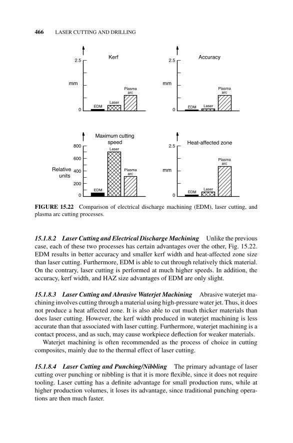
In the following sections, laser cutting is compared with specific alternate processes.Figure 15.21 starts with a numerical comparison of the laser, oxyacetylene, and plasmaarc cutting processes. This is followed in Fig. 15.22 with a graphical comparison ofelectrical discharge machining (EDM), laser cutting, and plasma arc cutting withrespect to kerf size, accuracy, maximum cutting speed, and heat-affected zone size.Additional comparison is then made with abrasive waterjet machining and punch-ing/nibbling.
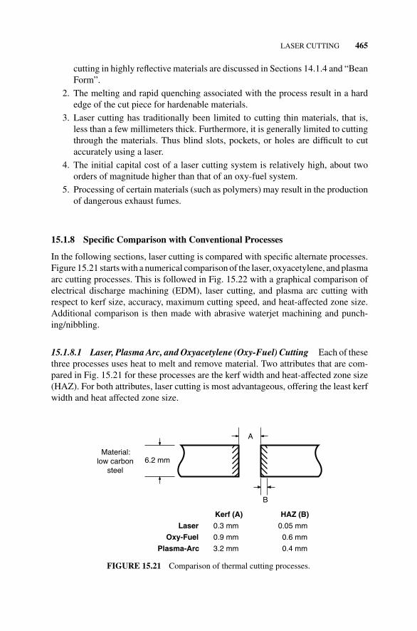
15.1.8.1 Laser, Plasma Arc, and Oxyacetylene (Oxy-Fuel) Cutting Each of thesethree processes uses heat to melt and remove material. Two attributes that are com-pared in Fig. 15.21 for these processes are the kerf width and heat-affected zone size(HAZ). For both attributes, laser cutting is most advantageous, offering the least kerfwidth and heat affected zone size.
A
B
6.2 mmMaterial:
low carbonsteel
Laser
Oxy-Fuel
Plasma-Arc
Kerf (A)
0.3 mm
0.9 mm
3.2 mm
HAZ (B)
0.05 mm
0.6 mm
0.4 mm
FIGURE 15.21 Comparison of thermal cutting processes.
15.1.8.2 Laser Cutting and Electrical Discharge Machining Unlike the previouscase, each of these two processes has certain advantages over the other, Fig. 15.22.EDM results in better accuracy and smaller kerf width and heat-affected zone sizethan laser cutting. Furthermore, EDM is able to cut through relatively thick material.On the contrary, laser cutting is performed at much higher speeds. In addition, theaccuracy, kerf width, and HAZ size advantages of EDM are only slight.
15.1.8.3 Laser Cutting and Abrasive Waterjet Machining Abrasive waterjet ma-chining involves cutting through a material using high-pressure water jet. Thus, it doesnot produce a heat affected zone. It is also able to cut much thicker materials thandoes laser cutting. However, the kerf width produced in waterjet machining is lessaccurate than that associated with laser cutting. Furthermore, waterjet machining is acontact process, and as such, may cause workpiece deflection for weaker materials.
Waterjet machining is often recommended as the process of choice in cuttingcomposites, mainly due to the thermal effect of laser cutting.
15.1.8.4 Laser Cutting and Punching/Nibbling The primary advantage of lasercutting over punching or nibbling is that it is more flexible, since it does not requiretooling. Laser cutting has a definite advantage for small production runs, while athigher production volumes, it loses its advantage, since traditional punching opera-tions are then much faster.
LASER CUTTING 467
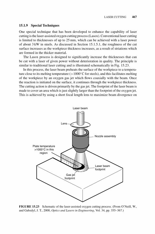
15.1.9 Special Techniques
One special technique that has been developed to enhance the capability of lasercutting is the laser-assisted oxygen cutting process (Lasox). Conventional laser cuttingis limited to thicknesses of up to 25 mm, which can be achieved with a laser powerof about 3 kW in steels. As discussed in Section 15.1.5.1, the roughness of the cutsurface increases as the workpiece thickness increases, as a result of striations whichare formed in the thicker material.
The Lasox process is designed to significantly increase the thicknesses that canbe cut with a laser of given power without deterioration in quality. The principle issimilar to traditional laser cutting and is illustrated schematically in Fig. 15.23.
In this process, the laser beam preheats the surface of the workpiece to a tempera-ture close to its melting temperature (>1000◦C for steels), and this facilitates meltingof the workpiece by an oxygen gas jet which flows coaxially with the beam. Oncethe reaction is initiated on the surface, it continues through the workpiece thickness.The cutting action is driven primarily by the gas jet. The footprint of the laser beam ismade to cover an area which is just slightly larger than the footprint of the oxygen jet.This is achieved by using a short focal length lens to maximize beam divergence on
Laser beam
Lens
Nozzle assembly
Laser beamfootprint
Gas jetfootprint
Plate temperature>1000°C in this
region
FIGURE 15.23 Schematic of the laser-assisted oxygen cutting process. (From O’Neill, W.,and Gabzdyl, J. T., 2000, Optics and Lasers in Engineering, Vol. 34, pp. 355–367.)
468 LASER CUTTING AND DRILLING
leaving the nozzle, and yet maintain reasonable standoff distances. As an illustration,20–50 mm steel plates can be cut with laser power levels of 700–1100 W at speedsof 0.15–0.5 m/min if the beam diameter on the workpiece surface is 4 mm, gas jetdiameter is 3 mm, nozzle exit diameter is 2.5 mm, gas pressure is about 8 bar, andthe beam absorptivity is 30%.
The surface quality obtained under these conditions is much better than that ob-tained by either oxyacetylene cutting alone or by traditional laser cutting, which wouldrequire much higher power. The taper that results is also less than 1◦, and the top edgeis square.
15.2 LASER DRILLING
Laser drilling is used in such applications as jet engine turbine airfoils, injector noz-zles, watches, and so on. The process involves applying a laser beam to heat up thematerial to its melting point or vaporization temperature. When vaporization occurs,it generates a keyhole that results in increased absorptivity, further increasing the holedepth. The molten material or vapor formed is blown away using an assist gas. Whenthe vapor or molten material is ejected out into the surrounding atmosphere, some ofit may condense on the workpiece surface as spatter. Very small diameter holes (ofthe order of microns) can be drilled using a laser, resulting in high aspect ratios.
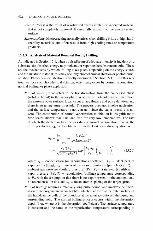
Our discussion on laser drilling starts with an outline of the different ways inwhich a laser may be used to drill a hole, followed by a discussion of the basicprocess parameters. An analysis of the process is then presented, first mentioningthe governing equations that will need to be used for a rigorous analysis, followedby an approximate analysis that enables the drilling velocity to be estimated. Theadvantages and disadvantages of laser drilling are then presented, and finally, potentialapplications.
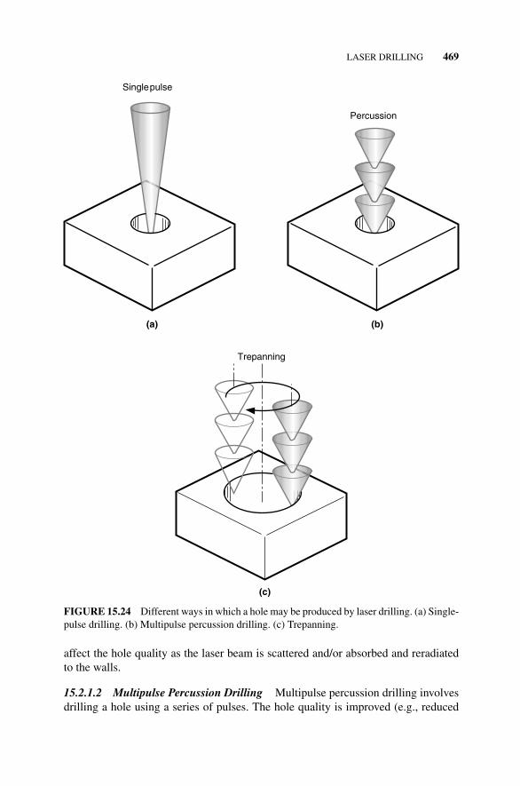
15.2.1 Forms of Laser Drilling
There are three ways in which a hole can be produced by laser drilling (Fig. 15.24):
1. Single-pulse (or on-center) drilling.
2. Multipulse percussion drilling.
3. Trepanning.
15.2.1.1 Single-Pulse Drilling This form of drilling involves using a single pulseof laser beam, with a pulse duration of about 1 ms, and energy of several Joules,resulting in a peak power of the order of 10–100 kW. The material in contact with thelaser beam is partly melted and partly evaporated, and blown out backward using a gasjet to form the hole. The exceedingly high energy required for drilling very deep holesmay result in poor tolerances; reduce the pulse frequency obtainable with the laser,thereby reducing productivity; and increase plasma formation. Plasma formation may
LASER DRILLING 469
Singlepulse
(a)
Percussion
(b)
Trepanning
(c)
FIGURE 15.24 Different ways in which a hole may be produced by laser drilling. (a) Single-pulse drilling. (b) Multipulse percussion drilling. (c) Trepanning.
affect the hole quality as the laser beam is scattered and/or absorbed and reradiatedto the walls.
15.2.1.2 Multipulse Percussion Drilling Multipulse percussion drilling involvesdrilling a hole using a series of pulses. The hole quality is improved (e.g., reduced
470 LASER CUTTING AND DRILLING
tapering along the hole length) since the peak power required is reduced, and with it,the amount of molten material and plasma produced during any single pulse period.However, the series of pulses used reduces the production rate. Typical pulse durationranges from about 100 fs to 2 ms.
In both percussion modes, the molten and/or evaporated material is ejected out ofthe hole by the excess pressure of the gas or plasma in the hole over ambient, and thisincreases with the beam intensity. With increasing hole depth, the pressure required toblow out the molten material increases accordingly. One disadvantage of percussiondrilling is that the material that is removed is blown backward toward the lens.
15.2.1.3 Trepanning Trepanning involves cutting out the hole by performing arelative motion (circular or noncircular) between the laser beam and the workpiece.The process is essentially one of laser cutting. Thus large diameter holes can be pro-duced, with improved hole quality and repeatability. Another advantage of the processis that the material that is removed is blown away from the lens. However, the processis time consuming, typically requiring about 1 s for producing a hole. Holes drilledby this method are often limited to depths less than 12 mm.
15.2.2 Process Parameters
The type of laser selected for a given application is determined largely by the drillingtechnique used, the material, and geometry of the hole to be drilled. Nd:YAG lasersare more extensively used in drilling metals than CO2 lasers when thicknesses exceed0.5 mm, since absorption of the shorter wavelength 1.06 �m energy by the plasmaformed is relatively small, compared to absorption at the 10.6 �m wavelength of theCO2 laser. Furthermore, higher peak pulse powers are attainable with the Nd:YAGlaser. However, both the capital and running costs of CO2 lasers are lower than thoseof the Nd:YAG lasers of equivalent power.
The principal parameters associated with percussion laser drilling may be broadlycategorized as the beam characteristics (inputs), process characteristics (outputs), andprocess defects. These are further discussed in the following paragraphs.
15.2.2.1 Beam Characteristics The principal beam characteristics that influencethe drilling process include pulse energy, pulse duration, number of pulses, and beamquality. A typical value of the power density used would be 5 × 10⁷ W/cm2 at a peakpower of 8 kW, using a lens of focal length 100 mm.
Pulse Energy: The hole depth generally increases with increasing pulse energy.At much higher energy levels, however, there tends to be greater deformationat the top surface.
Pulse Duration: Laser drilling pulses typically fall in the range of 100 fs to 2 ms.Higher quality holes, (e.g., reduced taper and distortion), are obtained withshorter beam pulses. However, the number of pulses required to drill a givenhole then increases.
LASER DRILLING 471
Number of Pulses: Generally, hole taper can be reduced in holes with a highdepth-to-diameter ratio by using a relatively large number of pulses, while forlow depth-to-diameter holes, fewer pulses result in a better quality hole.
Beam Quality: Beams of lower M2 values or higher quality can be focused to asmaller diameter and also have a longer depth of focus. This increases pen-etration depth for drilling and cutting, while improving hole quality (highdepth-to-diameter ratio with reduced taper), especially for small diameterholes.
15.2.2.2 Drilling Characteristics The principal characteristics of the laser drillingprocess include the hole diameter, depth, and drilling angle.
Hole Diameter: Typical diameters of laser drilled holes range in size from 1 �mto 1.5 mm. Hole sizes smaller than 1 �m have been produced using femtosec-ond lasers. Maintaining a reasonable depth of focus for holes smaller than12.7 �m is difficult with traditional lasers. For holes of diameter greater than1.5 mm, it might be more appropriate to use trepanning, which is a relativelyslower process.
Hole Depth: In using Nd:YAG lasers, depth to diameter ratios as high as 30:1can be achieved.
Drilling Angle: This is the angle that the hole or beam axis makes with theworkpiece surface. The power density incident on the workpiece surface ismaximum when the workpiece is normal to the beam axis. This configurationalso permits the widest range of focal lengths and focusing angles. The draw-back, however, is that it results in any reflected beam being redirected back intothe optical system. Furthermore, material expelled during the process may bedeposited on the lens. This problem may be mitigated by the use of a coaxialgas flow or protective transparent cover plate for the lens.
Increasing the angle between the hole axis and the normal to the workpiece surfacereduces the amount of reflected beam and debris that is directed at the lens. How-ever, short focal length lenses are then more difficult to use, and so are gas nozzles.Furthermore, since the beam is then spread over a wider area, the power density isreduced.
15.2.2.3 Process Defects The product quality is affected by defects such as taperof the hole walls, recast, and microcracking.
Taper: Erosion of molten and vaporized material from the hole, and the conicalshape of the focused beam, together result in tapering of the drilled hole. Theextent of taper is influenced by the pulse energy, number of pulses, and opticalsystem design. It can be minimized by using long focal length lens, which tendto have longer depth of focus. Tapering is usually not a problem for very smallhole depths, say, less than 0.25 mm.
472 LASER CUTTING AND DRILLING
Recast: Recast is the result of resolidified excess molten or vaporized materialthat is not completely removed. It essentially remains on the newly createdsurface.
Microcracking: Microcracking normally arises when drilling brittle or high hard-enability materials, and often results from high cooling rates or temperaturegradients.
15.2.3 Analysis of Material Removal During Drilling
As indicated in Section 15.1, when a pulsed beam of adequate intensity is incident on asubstrate, the absorbed energy may melt and/or vaporize the substrate material. Theseare the mechanisms by which drilling takes place. Depending on the energy sourceand the substrate material, this may occur by photochemical ablation or photothermalablation. Photochemical ablation is briefly discussed in Section 15.1.1.3. In this sec-tion, we focus on photothermal ablation, which may occur by normal vaporization,normal boiling, or phase explosion.
Normal Vaporization: refers to the transformation from the condensed phase(solid or liquid) to the vapor phase as atoms or molecules are emitted fromthe extreme outer surface. It can occur at any fluence and pulse duration, andthere is no temperature threshold. The process does not involve nucleation,and the surface temperature is not constant since the vapor pressure is notzero. The contribution of normal vaporization to ablation is insignificant attime scales shorter than 1 ns, and also for very low temperatures. The rateat which the drilled surface recedes during normal vaporization, that is, thedrilling velocity, ud, can be obtained from the Hertz–Knudsen equation as
ud = ∂z
∂t
∣∣∣∣∣z=0
= kcPsλa3
√(2πmmkBT )
≈ kcPaλa3
√(2πmmkBT )
exp
[Lvmm
kB
(1
Tv− 1
T
)](15.20)
where kc = condensation (or vaporization) coefficient, Lv = latent heat ofvaporization (J/kg), mm = mass of the atom or molecule (particle)(kg), Pa =ambient gas pressure (boiling pressure) (Pa), Ps = saturated (equilibrium)vapor pressure (Pa), Tv = vaporization (boiling) temperature correspondingto Pa, with the assumption that there is no vapor present in the ambient, andno recondensation (K), and λa = mean atomic spacing of the target (�m).
Normal Boiling: requires a relatively long pulse period, and involves the nucle-ation of heterogeneous vapor bubbles which may form at the outer surface ofthe liquid; in the bulk of the liquid; or at the interface between the liquid andsurrounding solid. The normal boiling process occurs within the absorptiondepth (1/α, where α is the absorption coefficient). The surface temperatureis constant and the same as the vaporization temperature corresponding to
LASER DRILLING 473
the pressure at the surface. The temperature gradient at the surface and alsodirectly beneath it is zero (i.e., ∂T/∂z = 0).
For phase explosion: (also known as explosive boiling) to occur, the laserfluence has to be sufficiently high and the pulse duration sufficiently shortsuch that the temperature of the surface and the region immediately beneathit reaches about 90% of the thermodynamic critical temperature (i.e. 0.90Tct).That results in homogeneous bubble nucleation, and the material undergoes arapid transition from a superheated liquid to a vapor/liquid droplet mixture.Homogeneous nucleation is feasible since the rate at which it occurs increasessignificantly near the critical temperature. Here too, the temperature gradientat the surface and also directly beneath it is zero.
Now we focus again on normal vaporization where the substrate material is firstheated through the melting point to the vaporization temperature. In this case, part ofthe beam energy is used to melt the substrate, and the molten material (liquid layer)formed is in direct contact with the substrate. Part of this molten material is furthervaporized by the beam. The vapor produced creates a vapor or recoil pressure whichpushes the vapor away from the target and also exerts a force on the molten materialand expels it sideways.
Material removal may thus occur in both liquid and vapor forms. In the liquidform, the thickness of the liquid layer is estimated to be of the order of 10 �m, anddecreases with increasing power. In the vapor form, the vaporization rate increaseswith an increase in power. However, the liquid expulsion rate increases to a maximum,and then decreases. At lower power, the vapor temperature is low. Consequently,the expulsion rate is low because of low recoil pressure. At high power, the vaportemperature is high. However, the thickness of the liquid layer is then so small that theliquid expulsion rate is also reduced. Generally, at low beam power, liquid expulsion isthe predominant form of material removal, while vaporization is the predominant format high power. The process of liquid expulsion is illustrated in Fig. 15.25. For beamsof much greater intensity and shorter pulse duration, the resulting recoil pressuremay be so high as to induce shock waves which are transmitted through the material.Shock waves may also be generated as a result of the interaction of the laser with theplasma. This phenomenon resembles that of combustion waves.
In the next section, a fundamental approach for analyzing the laser drilling pro-cess is outlined. Since the governing equations on which this approach is based arenonlinear, they can only be fully solved using numerical methods. Therefore, in thesubsequent section, we present an approximate method for obtaining a quick estimateof the rate at which laser drilling takes place.
15.2.3.1 Basic Analysis The governing equations necessary for analyzing the laserdrilling process are the basic continuity, momentum, and energy equations, with theappropriate boundary conditions. There are two interfaces associated with the materialremoval process. One is the solid–liquid interface that can be treated as a conventionalStefan problem, (Section 12.1.1). The other is the liquid–vapor interface, adjacent towhich may exist a Knudsen layer with a thickness of a few molecular mean free paths.
474 LASER CUTTING AND DRILLING
Liquidδλ
Vapor
VaporizationLiquid
expulsion
Liquidexpulsion
Laser
Solid
uv
uλ
FIGURE 15.25 Schematic of material removal by a pulsed beam. (From Chan, C., andMazumder, J., 1987, Journal of Applied Physics, Vol. 62, pp. 4579–4586.)
Across this layer, continuum theories are no longer valid since discontinuities exist intemperature, density, and pressure. The discontinuity across the Knudsen layer is thebasis for the shock wave. To understand the system’s behavior under these conditions,we focus on the process of surface evaporation, which is illustrated schematically inFigs 15.26 and 15.27.
To simplify the analysis, we make the following assumptions:
1. The process occurs under quasi-equilibrium conditions involving evaporationfrom a plane liquid–vapor interface into air at ambient conditions.
2. The vapor is an ideal gas.
3. Thermodynamic equilibrium exists in the liquid.
4. Diffusive evaporation is negligible compared to convective evaporation.
5. Immediately in contact with the liquid surface is a thin layer of vapor whosethickness may be several mean free paths in size, known as the Knudsen layer,which is a discontinuity region where the change in temperature, pressure, anddensity across the evaporation front are discontinuous.
6. Flow just outside the Knudsen layer is subsonic.
Using the conservation of mass, momentum, and translational kinetic energy, thetemperature, pressure, and density in the vapor at the edge of the Knudsen layer(subscript v) can be related to the corresponding properties at the liquid surface
LASER DRILLING 475
Shockwave
Contactdiscontinuity
liquidsubstrate
(a)
Knudsenlayer
Air
Air
Vapor
Liquid
t
x
Knudsen layer
Contact discontinuity
Shock wave
Air
(b)
Air
Vapor
Evaporatingsurface
FIGURE 15.26 Schematic of the evaporation process under subsonic conditions. (a) Thedifferent zones. (b) Variation of the different zones with time. (From Knight, C. J., 1979,AIAA Journal, Vol. 17, pp. 519–523. Reprinted by permission of the American Institute ofAeronautics and Astronautics, Inc.)
(subscript l) and saturated vapor conditions (subscript s), taking into account thediscontinuity across the Knudsen layer. The relationships are given by
Tvk
Tl=
⎡⎣
√1 + π
(mu(γv − 1)
2(γv + 1)
)2
− √π
mu(γv − 1)
2(γv + 1)
⎤⎦
2
(15.21)
ρv
ρs=
√Tl
Tvk
[(mu
2 + 1/2)emu2erfc(mu)− mu√
π
]+ Tl
2Tvk
[1 − √
πmuemu2erfc(mu)
](15.22)
476 LASER CUTTING AND DRILLING
Air
Air
Vapor
Shockwave
Contactdiscontinuity
Liquidsubstrate
(a)
Knudsenlayer
Rarefaction fan
t
x
Knudsen layer
Contact discontinuity
Shock wave
Rarefaction fan
Air
(b)
Air
VaporEvaporating
surface
FIGURE 15.27 Schematic of the evaporation process under supersonic conditions. (a) Thedifferent zones. (b) Variation of the different zones with time. (From Knight, C. J., 1979,AIAA Journal, Vol. 17, pp. 519–523. Reprinted by permission of the American Institute ofAeronautics and Astronautics, Inc.)
There is a pressure rise at the liquid–vapor interface, and this propagates as apressure wave. The pressure change across the wave front, which may be consideredas a pressure discontinuity, is given by
Pv
Pa= 1 + γaMh
uv
ua
⎡⎣γa + 1
4Mh
uv
ua+
√1 +
(γa + 1
4Mh
uv
ua
)2⎤⎦ (15.23a)
Mh = mu
√2
γv(15.23b)
where cp and cv are the specific heats at constant pressure and volume, respectively
(J/kg K); erfc(mu) = 2√π
∫ ∞mu
e−x2dx = complementary error function; mu is the
LASER DRILLING 477
uk√2RgvTvk
(m kg1/2/sJ1/2); Mh is the flow Mach number of the vapor leaving the Knud-
sen layer; mg is the molecular weight of the ambient gas (kg/mol); mv is the molecularweight of the vapor (kg/mol); Pa is the ambient pressure (Pa); Ps is the saturatedvapor pressure (Pa); Pv is the vapor pressure (Pa); Pvk is the vapor pressure at theedge of the Knudsen layer (Pa); Rg = 8.314 is the universal gas constant (J/mol
K); Rga = Rgmg
is the gas constant for the ambient gas (J/kg K); Rgv = Rgmv
is the gasconstant for the vapor (J/kg K); Ta is the ambient temperature (K); Tl is the liquidtemperature at the vaporizing surface (K); Tvk is the vapor temperature at the edge ofthe Knudsen layer (K); uk is the mean vapor velocity at the edge of the Knudsen layer(m/s); ua is the speed of sound in the ambient gas (m/s); uv is the speed of sound inthe vapor (m/s); �Hvm is the molar enthalpy of vaporization (J/mol); γa is the ratioof specific heats for the ambient gas; γv = cp/cv is the ratio of specific heats for thevapor, considering the vapor to be a monatomic gas; ρs refers to the saturated vapordensity at the liquid temperature, Tl (kg/m3); ρv refers to the vapor density at the edgeof the Knudsen layer (kg/m3).
In analyzing the vapor pressure, two cases have to be distinguished:
1. Subsonic flow just outside the Knudsen layer, Fig. 15.26a and b
2. Supersonic flow just outside the Knudsen layer, Fig. 15.27a and b.
Subsonic Flow: The Mach number for flow outside the Knudsen layer is less thanone, that is Mh < 1. The following conditions then exist:
Ps
Pa= Pv
Pa
/Pv
Ps(15.24a)
Ps
Pv= ρs
ρv
Tl
Tvk(15.24b)
uv = √γvRgvTvk ua = √
γaRgaTa (15.24c)
Supersonic Flow: The Mach number for flow outside the Knudsen layer is greaterthan one, that is Mh > 1. However, flow within, and at the outside edge of theKnudsen layer is one, that is, Mh = 1. The following conditions then exist:
Ps
Pa= Pvk
Pv
Pv
Pa
/Pvk
Ps(15.25a)
Pvk
Pv=
[2
γv + 1+ γv − 1
γv + 1Mh
] 2γvγv−1
(15.25b)
uv
ua=
√[γvRgvTlTvk
γaRgaTaTl
] [2
γv + 1+ γv − 1
γv + 1Mh
]−1
(15.25c)
478 LASER CUTTING AND DRILLING
Pvk
Ps= 0.206
Tvk
Tl= 0.669 (15.25d)
Considering the subsonic case, equations (15.21)–(15.23) contain eight un-knowns, namely, Tvk, Tl, ρv, ρs, Pv, Ps, mu, and Mh. The equation of state
P = ρRgvT (15.26)
can be used for saturated and expanding vapor states, along with a Clausius-Clapeyron equation:
Ps = kce− �Hvm
RgTl (15.27)
to express all the variables in terms of Tl. In equation (15.27), kc is a con-stant. Energy balance at the evaporation front provides the missing equationto determine the thermodynamic state of the saturated vapor.
15.2.3.2 Approximate Analysis In this section, we develop a simple extension ofthe Hertz-Knudsen equation for estimating the rate (velocity) of the drilling process,which takes into account the contribution of the ejected molten material. The followingassumptions are made:
1. Heat conduction and vapor absorption losses are negligible.
2. The thermal properties of the material are constant, and thermal expansion isnegligible.
3. The skin depth (≈ 10−5 mm) (see Section 14.1.6) is negligible.
If we consider the energy flux carried away with the expulsed material to be equalto the irradiance or power density (power per unit area) absorbed by the material, Ia,then we can write (cf. equation (10.1)):
Ia = φv�Hv + φl�Hl (15.28)
where�H = specific energy absorbed by the expulsed material (J/kg),φ = expulsionrate (kg/m2 s) and the subscripts v and l refer to the vapor and liquid, respectively.
The drilling velocity, ud, can be expressed in terms of φv and φl as
ud = 1
ρ(φv + φl) (15.29)
In developing an expression for φl, one may consider a simple one-dimensionalconduction heat flow for a system with a constant moving heat source. The quasistatictemperature distribution, T , in the medium for this case, neglecting any phase changes
LASER DRILLING 479
and lateral heat conduction losses, may be approximated as
T = Ia′
ρcpudexp
(−ξud
κ
)(15.30)
where Ia′ = Ia − φvLv is the difference between the absorbed power density and that
carried away from the absorbing layer by the evaporated material (W/m2); Lv is thelatent heat of vaporization (J/kg); ud is the drilling velocity (m/s); κ is the thermaldiffusivity of the material (m2/s); ξ is the moving coordinate pointing in the directionof ud.
The rate of evaporation, φv, of a hot surface at a temperature Th is obtained fromthe Hertz–Knudsen equation as
φv = (1 − R)Ps
(mm
2πkBTh
)1/2
(15.31)
where kB is Boltzmann’s constant (J/K), mm is the mass of the atom or molecule(particle) (kg), and R ≈ 0.2 is the mean particle reflection coefficient of the metalsurface.
The saturated vapor pressure, Ps, may be obtained from equation (15.24), or maybe approximated by
Ps = Paexp
[Lp
kBTv
(1 − Tv
Th
)](15.32)
where Lp is the heat of evaporation per particle (J/particle), Pa is the ambient pressure(Pa), Th is the hot surface temperature (K), and Tv is the evaporation temperature (K).
The hot surface temperature, Th, may be estimated as the temperature at ξ = 0in equation (15.30). Then again considering heat balance, but only for the moltenmaterial, we have
∫ Th
T0
cpdT + Lm = I ′a
ρud(15.33)
where Lm is the latent heat of melting (J/kg) and T0 = Ta is the ambient temperature(K).
The thickness, δl, of the liquid layer formed by heat conduction may be estimatedusing equation (15.30) as
δl =(
κ
ud
)ln
(Th
Tm
)(15.34)
where Tm is the melting temperature.
480 LASER CUTTING AND DRILLING
The pressure, P , of the evaporating surface acting on the liquid layer pushes theliquid radially outward with a velocity, ul, determined using Bernoulli’s equation(15.1a) as
ul =(
2P
ρ
)1/2
(15.35)
The expelled liquid escapes through an opening (Fig. 15.25) that is determined bythe beam radius, w, of an area Ae given by
Ae = 2πwδl (15.36)
Since the actual pressure P is about half the saturation pressure Ps (equation(15.24) or (15.32)), the liquid expulsion rate, φl, with respect to the irradiated surfaceis obtained from equations (15.35)–(15.37) as
φl =[(
2κ
w
)ln
(Th
Tm
)]1/2
Ps1/4ρ3/4 (15.37)
Equations (15.31), (15.32), and (15.37) give the expulsion rates of the vapor andliquid in terms of the surface temperature, Th. However, Th, in turn, depends on φland φv, (equation (15.33)). Thus, actual calculation of the expulsion rates will needto be done iteratively. However, for a first approximation, the surface temperature,Th, may be estimated from equation (15.30) and assumed constant.
It must be noted that the drilling speed calculated by this approach refers to theaverage rate at which material is removed during the laser pulse. It does not give theoverall production rate. The latter can be obtained simply by determining the depthof material removed for each pulse and multiplying that by the pulse repetition rate.
Example 15.3 An Nd:YAG laser generates pulses of intensity 60 MW/cm2 fordrilling 200 �m diameter holes in a tungsten plate. Estimate the drilling speed thatcan be achieved for this operation. Assume ambient temperature and pressure of 25◦Cand 0.1 MPa, respectively, and that the diameter of the hole is the same as the beamdiameter.
Solution:
Some of the material properties are obtained from Appendices 10D and 10E as
14.69 × 10⁻¹⁹ J/particleIncident power density is given by Ia = 60 MW/cm2 = 60 × 104 W/mm2
Thermal diffusivity, κ = kρcp
= 0.151219.254×10−6×134
= 58.6 mm2/s = 58.6 ×10⁻⁶ m2/s.
We assume an initial value for the drilling speed of 2.5 × 104 mm/s = 25 m/s,which is used to estimate the hot surface temperature using equation (15.30):
T − T0 = Ia′
ρcpudexp
(−ξud
κ
)
but
Ia′ = Ia − φvLv
Since φv is not known, we initially use Ia′ = Ia to estimate the hot surface tem-
perature.From equation (15.33), assuming a constant specific heat, the hot surface temper-
ature can be expressed as
Th = T0 + Ia
ρcpud− Lm
cp
or
Th = 25 + 60 × 104
19.254 × 10−6 × 134 × 2.5 × 104 − 22 × 104
134
⇒ Th = 7686◦C = 7959 K
482 LASER CUTTING AND DRILLING
Now from equation (15.32), the saturation pressure is given by
Ps = Pa exp
[Lp
kBTv
(1 − Tv
Th
)]
Now Pa = 105 N/m2 = 0.1 N/mm2. Thus,
Ps = 0.1 × exp
[14.69 × 10⁻¹⁹
1.38 × 10−23 × 5973
(1 − 5973
7959
)]
= 8.537 MPa (N/mm2) = 8.537 × 10⁶ Pa (N/m2)
Therefore, from equation (15.31),
φv = (1 − R)Ps
(mp
2πkBTh
)1/2
= (1 − 0.2) × 8.537 × 106
(3.05 × 10⁻²⁵
2π × 1.38 × 10−23 × 7959
)1/2
= 4540 kg/m2s
And from equation (15.37)
φl =[(
2κ
w
)ln
(Th
Tm
)]1/2
Ps1/4ρ3/4
=[(
2 × 58.6 × 10−6
0.100 × 10⁻³
)ln
(7959
3683
)]1/2
× [8.537 × 106]1/4 × [19254]3/4
= 8.4 × 10⁴ kg/m2s
This indicates that under these conditions, melting is the predominant mode ofmaterial removal. Now from equation (15.29), the drilling velocity is given by
ud = 1
ρ(φv + φl)
ud = 1
19254(84000 + 4540)
= 4.6 m/s = 4.6 × 103 mm/s
This is about an order of magnitude lower than the original estimate. Thus aniteration is necessary. The calculated value for φv can be used to update the value ofIa
′ during the iteration process.
LASER DRILLING 483
15.2.4 Advantages and Disadvantages of Laser Drilling
15.2.4.1 Advantages The advantages that laser drilling has over conventionaldrilling are the following:
1. It is a noncontact process. There are no machining forces, and thus no deflectionof a tool and/or workpiece that would result in dimensional errors in the partproduced, or wear of the tool.
2. Accurate location of holes. In conventional drilling, the drill often deflectson coming in contact with the workpiece, resulting in drill “wandering”. Thisaffects accuracy of hole location and orientation.
3. There is no chip formation, and thus no need for elaborate chip disposal systems.However, an appropriate exhaust system is often necessary for the vaporizedmaterial.
4. Laser drilling results in high depth to diameter aspect ratios, but primarily forholes of relatively small diameter, and depths of a few millimeters.
5. Ability to drill difficult-to-machine materials such as diamond, ceramics, andhighly refractory metals, on which conventional drilling performs poorly.
6. Ability to drill holes with difficult entrance angles. Drilling of holes with lowentrance angles is quite difficult with conventional drills. However, with laserdrilling, entrance angles as low as 10◦ are possible.
7. Ability to drill very small holes. Small diameter conventional drills are liableto break easily. On the contrary, the lower end of hole sizes that can be drilledusing a laser is limited by the beam size at the focal point, with hole sizes ofthe order of microns being achievable.
8. High degree of flexibility, enabling a number of operations to be combined ina single setup.
9. High duty cycles and high production rates. Since lasers can be used continu-ously without interruption, high duty cycles are achieved, resulting in relativelyhigh production rates.
15.2.4.2 Disadvantages The primary limitations of the laser drilling process in-clude the following:
1. Inability to produce precision blind holes. Lasers are more suited to producingthrough holes.
2. Inability to drill deep holes. The hole depths that are achieved by laser drillingare relatively small, being typically a few millimeters deep. As the hole depthincreases, the diameter begins to enlarge due to beam expansion, resulting in atapered hole.
3. Holes that are close to an edge, and those that intersect other holes are often noteffectively produced by laser drilling.
484 LASER CUTTING AND DRILLING
15.2.5 Applications
Typical applications for holes drilled using Nd:YAG lasers include holes in jet engineturbine airfoils and combustors (hole sizes about 180 �m −1 mm); injector nozzles;oil passages in automotive engine or gear components. Since CO2 lasers are moreeffectively used on non-metals, typical drilling applications involving CO2 lasers in-clude sound suppression holes in aircraft engine liners made of polymers or polymericcomposites; drilling holes in ceramic substrates in the microelectronic industry; andcigarette paper perforating.
15.3 NEW DEVELOPMENTS
15.3.1 Micromachining
Micromachining involves machining applications that result in feature sizes on theorder of tens of micrometers or less. As indicated in the section on laser drilling, holediameters of the order of a few microns can be produced using traditional lasers, withpulse durations ranging from continuous wave to hundreds of picoseconds. Commonlasers used for this purpose include the CO2, Nd:YAG, copper vapor, and excimerlasers. However, the mechanism of material removal with such long pulse lasers in-volves both melting and evaporation (Fig. 15.25). This results in significant drossformation (Section 15.1.5.2), which affects hole quality. Excimer lasers, being theexception, result in direct photochemical ablation (Section 15.1.1.3) due to the ultra-violet wavelength of the beam, and that improves the hole quality.
When a laser beam is incident on a material, the photon energy is first absorbedby electrons which then get heated to high temperatures rapidly. The electron energygets transferred to the lattice through electron–phonon collisions (Section 10.2.6),resulting in heating of the lattice. The extent of lattice heating depends on the pulseduration and the electron–phonon coupling. For long pulse durations, the electronsand lattice can reach thermal equilibrium, and a relatively large portion of the latticegets heated by diffusion, with a resulting peak temperature that is relatively low.The material is then first heated through the melting temperature to the vaporizationtemperature (if the power is high enough). A relatively large volume around the laserfocus melts, but only a relatively small layer of material reaches the vaporizationtemperature.
As the pulse duration decreases, the laser field intensity increases, and the interac-tion time gets shorter. Thus, for much shorter pulse durations, the intensity is muchhigher, resulting in relatively high electron temperatures (of the order of tens of elec-tron volts) during the pulse. Most of the electron–phonon coupling takes place afterthe pulse, and often results in lattice temperatures that are higher than are achievedwith long pulses for the same total energy (Section 14.1.4). Most of the heating isconfined to the interaction zone and passes rapidly through the melting temperature tothe vaporization temperature. Thus, a large fraction of the material in the interactionvolume is vaporized, going through a melt phase very quickly. With ultrashort pulses,
NEW DEVELOPMENTS 485
Laser beam
Thresholdintensity
Laserintensity
distribution
Workpiece
FIGURE 15.28 Setting the breakdown threshold to a specific level of beam mode. (FromLiu, X., Du, D., and Mourou, G., 1997, IEEE Journal of Quantum Electronics, Vol. 33, No.10, pp. 1706–1716.)
when the laser fluence just exceeds the threshold value, the region that is vaporizedcan be smaller than the focal area (Fig. 15.28).
Ultrashort pulse lasers (≤ 1 ps) with wavelengths in the visible and near infraredrange therefore result in high precision micromachining, with clean and uniform holesor cuts. The breakdown threshold of such lasers can be determined with high accuracysince it is deterministic. Since the beam intensity profile can be controlled such thatonly a specified portion of the focused beam spot is above the threshold (Fig. 15.28),a region of diameter smaller (1 �m or less) than the focused beam size (5 �m or less)can be ablated, with barely any heat being conducted out of the processing zone. Themechanics of laser–material interaction that results in ablation under such conditionsare discussed in the following paragraphs.
Absorption of a laser beam that is incident on a material occurs by linear or non-linear processes. The absorption results in heating of material in the focal region firstto the melting temperature and then to the vaporization temperature, depending onthe beam intensity and pulse duration. For radiation outside the ultraviolet range, theabsorption mechanisms are different for materials such as metals and semiconductorswhich are absorbing, and glasses and plastics which are transparent dielectric ma-terials. Absorption also depends on laser intensity (pulse duration and fluence). Foropaque materials, absorption is linear when the beam pulse duration is long and theintensity low, while nonlinear absorption becomes dominant when the pulse durationis ultrashort and the intensity high.
15.3.1.1 Transparent Dielectric Materials Absorption for transparent materialsresults mainly from nonlinear processes. Avalanche ionization and multiphoton ion-ization are the nonlinear mechanisms that cause breakdown.
Avalanche Ionization The bound valence electrons of transparent dielectric materialshave an ionization potential or bandgap which is greater than the laser photon energy(Section 8.4.1). Therefore at low beam intensities (typical of long pulse lasers), the
486 LASER CUTTING AND DRILLING
laser energy is not absorbed by the bound electrons. However, a few free electrons(seed electrons) that exist in the material as a result of impurities do absorb laserenergy when they collide with bound electrons and lattice (inverse Bremsstrahlungprocess). Acceleration of the seed electrons provide them with kinetic energy thatis in excess of the ionization potential of the bound electron. Thus, as these seedelectrons collide with bound electrons, ionization occurs, resulting in additional freeelectrons, in much the same way that a photon interacting with an excited atom resultsin another photon being generated. Repetition of this process leads to an avalanchethat increases the free-electron density exponentially. At a critical density (1018/cm3
for pulse durations greater than a nanosecond), the transparent material breaks downand becomes absorbing. The absorption at the critical density is significant enoughthat irreversible damage takes place. At the critical density, the plasma oscillationfrequency equals the laser frequency, and the transparent material becomes totallyopaque. For ultrashort pulses, the critical density, ρe, is given by
ρe = meω2
4πe2 (15.38)
where me = electron mass and ω = laser frequency.The critical electron density is then about 1021/cm3 for lasers in the visible and
near-infrared wavelength range. The breakdown process typically results in the gen-eration of acoustic waves and radiation of optical plasma or spark at the focus.
Multiphoton Ionization At very high beam intensities, bound electrons of transparentmaterials are directly ionized (i.e., lifted from the valence band to the conductionband or free energy level) by multiphoton absorption. This is normally the case withultrashort pulse beams, and involves simultaneous absorption of m photons duringthe pulse such that
mhpν ≥ Eg (15.39)
where Eg is the bandgap energy or ionization potential.Generally for the critical density to be achieved that results in irreversible break-
down and therefore ablation, the laser fluence must exceed a threshold value, whichdepends on the pulse duration. For pulse durations longer than a few tens of picosec-onds, the threshold fluence is proportional to the square root of the pulse duration.Furthermore, there is significant scatter associated with the threshold fluence, mak-ing it more stochastic in nature. Avalanche ionization is the principal mechanismfor breakdown in this pulse duration range. For ultrashort pulses, the seed electronsare created by multiphoton ionization, but even though the actual breakdown pro-cess is primarily accomplished through avalanche ionization, the threshold is moredeterministic or precise.
15.3.1.2 Metals and Semiconductors Materials that are absorbing (such as met-als and semiconductors) generally have a significant number of free and valence
NEW DEVELOPMENTS 487
electrons whose ionization potential (bandgap) is smaller than the laser photon energy.Linear absorption is therefore the predominant mode when the laser pulse durationis long, resulting in Joule heating. Here too breakdown, which results in melting andvaporization, is accompanied by the generation of acoustic waves and radiation ofoptical plasma or spark at the focus.
There are two characteristic lengths associated with absorption of the laser beam.One is the skin depth, δ′ (Section 14.1.6), which is the distance within which thephoton energy is absorbed, and may be expressed as
δ′ = 1
α(15.40)
The other is the heat diffusion length, lh, which is the distance over which thethermal energy is conducted during the pulse, and can be expressed as
lh = √κτp (15.41)
where τp is the pulse duration.For long pulses, the fluence threshold varies as the square root of the pulse du-
ration since lh > δ′, and therefore the volume of material heated by the beam pulsedepends on the heat diffusion length. There is then significant scatter associated withthe threshold. Since the volume of material that is heated is relatively large, significantamount of melting occurs, and during ablation, material is expelled in both liquid andvapor form by the recoil (vapor) pressure associated with the ablation process (Sec-tion 15.2.3). The unexpelled molten material resolidifies around the ablated region,resulting in dross formation, (Fig. 15.29a). The thickness of melt layer that results forlong pulse lasers can be much as 10 times that of the evaporation layer. That meansthe feature sizes that can be obtained are relatively large.
When the pulse duration becomes short enough that lh < δ′, the threshold becomesindependent of the pulse duration, and is therefore more deterministic. Furthermore,since the energy absorbed is highly localized, the material in this region is quicklyheated through the melting temperature to the vaporization temperature. Most of theablation process then occurs by direct vaporization, resulting in more precise andcleaner cuts (Fig. 15.29b). A significant portion of the material is removed after thelaser pulse has ended. Even though heat diffusion results in heating of the surroundingmaterial, the amount of material that melts as a result is relatively small. This is duein part to the rapid cooling that follows the heating process, and also to the significantamount of energy that is lost by vaporization. With ultrashort pulse lasers, the meltthickness may only be about twice that of the evaporation layer. Thus, submicronfeature sizes are achievable.
The dependence of the fluence threshold on the square root of the pulse durationwhen lh > δ′ also applies to transparent materials.
Advantages of ultrashort pulse lasers in relation to material ablation can thereforebe summarized as the following:
488 LASER CUTTING AND DRILLING
FIGURE 15.29 SEM photographs of holes drilled through a 100 �m steel foil usingTi:sapphire laser pulses at 780 nm. (a) Pulse duration = 3.3 ns and fluence = 4.2 J/cm2 and(b) pulse duration = 200 fs and fluence = 0.5 J/cm2. (From Momma, C., Nolte, S., Chichkov,B. N., Alvensleven, F. V., and Tunnermann, A., 1997, Applied Surface Science, Vol. 109/110,pp. 15–19.)
1. The precision of the ablation (breakdown) threshold (which depends on thepulse duration, being higher for the longer pulse duration beam).
2. Reduction in the laser fluence needed to initiate ablation.
3. Significant reduction in heat affected zone size.
In recent years, ultrashort pulse lasers have found increasing use in machiningmicrochannels, such as those used in microfluidics. They have also been used to drillholes of diameter 35 �m in 1 mm thick stainless steel sheet, resulting in good qualityholes with straight sides. Hole sizes as small as 0.3 �m have been produced in silverfilms using 200 fs pulses produced by a Ti:sapphire laser, which was focused to aspot size of 3 � m. As with traditional lasers, femtosecond lasers can be used inmachining materials ranging from diamond to biodegradable polymers.
NEW DEVELOPMENTS 489
15.3.2 Laser-Assisted Machining
Laser-assisted machining is a means for increasing productivity in metal removalfor traditionally difficult-to-machine materials such as titanium alloys, nickel-basedsuperalloys, and hardened steels. The metal removal rate and productivity achievedwhen machining such materials by conventional methods are limited by the significantreduction in tool life at high speeds.
The process involves using a laser beam to heat up a portion of a material directlyin front of a cutting tool to a temperature lower than its melting point, but high enoughto soften the material ahead of the cutting tool (Fig. 15.30). Increasing the temperatureof a material normally decreases its flow stress and strain hardening rate. Ordinarily, itshould be possible to reduce the flow stress simply by machining at high speeds. Thisis feasible with materials such as aluminum alloys whose flow stress decrease rapidlywith increasing temperature. However, many of the difficult-to-machine materialstend to retain their strength at elevated temperatures. Thus high-speed machiningof such materials increases tool failure rate. In conventional machining, the chip ishottest at the underside which is in contact with the cutting tool, while the opposite istrue of laser assisted machining, even though in the latter case, the temperature of theunderside of the chip may be the same as that obtained in conventional machining.
Laser-assisted machining is essentially an improvement of the process of usinga gas torch or induction heating to facilitate the machining process. Gas torch andinduction heating are not commercially acceptable because of the resulting large heat-affected zone and distortion of the machine and workpiece. The high heat input alsoaffects the cutting tool. Some of the benefits of laser-assisted machining include
1. Reduction in cutting forces
2. Improvement in tool life
3. Improvement in surface finish.
Reduction in cutting forces increases the accuracy of cutting by decreasing theamount of workpiece and machine distortion. It also minimizes the tendency for toolfracture in interrupted cuts, especially when ceramic cutting tools are used. Lookingat it from another viewpoint, by keeping the cutting forces constant, higher feed ratescan be used, enabling higher material removal rates to be achieved. Improvement insurface finish of the workpiece improves its fatigue life as well as wear and corrosionresistance.
To minimize the effect of the applied heat on the cutting tool, the depth of heatpenetration into the shear zone has to be limited to a region above the cutting tool.By doing so, the workpiece is softened without overheating the cutting tool.
In laser-assisted turning of 316 and 420 stainless steels and the nickel superalloy,udimet 700, using a pulsed laser beam of power 460 W, with a maximum averagepower density of 2.3 MW/cm2, it has been found that the use of laser assist producesa smoother workpiece surface. Even though the 420 stainless steel does not show areduction in cutting forces, the improvement in surface finish obtained is significant.For the 316 stainless steel and 1018, 1040 plain carbon steels, force reductions in
490 LASER CUTTING AND DRILLING
Laser beam
Feed direction
Heat-affected zone
Chip
Cutting tool
Workpiece
(a)
Laser beam
Feed direction
ChipCuttingtool Workpiece
(b)
SpraynozzleAbsorptive
coating
Beamspot
FIGURE 15.30 Schematic of the laser-assisted machining process. (a) Two-dimensionalview and (b) three-dimensional view. (From Weck, M., and Kasperowski, S., 1997, Produc-tion Engineering, Vol. IV, No. 1, pp. 35–38. Permission of MIT Publishing Ltd. ProductionEngineering Solutions.)
the range of 25–50% can be expected. For 1090 steel, much higher forces (about2–3 times) are obtained with the laser on than when it is off. This is most likelydue to hardening of the workpiece by the laser beam through phase transformation.An improvement in surface quality, though, is obtained. It has been found that laser-assisted machining in general is not effective at very high machining speeds sincethe interaction time at an irradiated spot is too short for the metal to be heated at the
NEW DEVELOPMENTS 491
high speeds. At very low speeds, however, the material cools between the time that itis irradiated and the time it arrives at the tool. Hardenable materials thus experiencehigher forces at low speeds. For a previously hardened material, the cutting forcesare always reduced. For either type of material, the forces are reduced at intermediatespeeds that result in the maximum amount of tempering of the material arriving atthe tool.
Conventional machining of titanium alloys is normally done at relatively lowspeeds and exclusively with carbide cutting tools, due to the relative weakness ofceramics and the high reactivity of titanium. Also, the low thermal conductivityof titanium alloys tend to concentrate any heat generated in the immediate vicinityof the tool, accelerating tool failure. In laser-assisted machining of titanium alloys, ithas been found that effective results are obtained with the beam spot oriented suchthat its minor axis is along the direction of rotation (Fig. 15.30b). The amount of timethat any point on the workpiece is impinged by the beam is then minimal, therebyreducing heat penetration below the shear plane and into the cutting tool. This isespecially true when carbide tools are used, since they are less resistant to high tem-peratures than ceramic tools. Due to the low speeds, absorptive coatings may not benecessary. At a laser power level of 12 kW, cutting speed of 0.7 m/s, feed rate 0.38–2.00 mm/rev, and depth of cut 2.5 mm, productivity is doubled by increasing the feedrate if the cutting forces and tool wear are kept constant. The low conductivity of tita-nium alloys results in a reduced heat penetration, thereby reducing the impact of thelaser beam on tool wear. Since titanium alloys are normally machined at low speeds,much greater improvements can be expected with the application of laser-assistedmachining.
In laser-assisted machining of inconel 718 using ceramic tools with a laser powerof 12 kW, cutting speed of 2.0 m/s, feed rate 0.15 mm/rev, and depth of cut 1.3 mm, ithas been found that impinging the beam at the top edge of the shoulder substantiallyreduces notch wear at the depth of cut line, but has little influence on nose wear. Nosewear could be reduced by focusing the beam near the root of the shoulder, but thenthat results in no improvement in the notch wear. In either case, however, flank wearis reduced. The forces have been found to decrease almost linearly with increasinglaser power, with the rate being a little over 1% per kilowatt when no absorptivecoatings are used on the workpiece surface. With absorptive coatings, the reductionsaverage nearly 4% per kilowatt at power levels up to 4 kW. However, at power levelsgreater than 4 kW, the force curves level out, indicating a progressive decrease inabsorptivity. At a speed of 0.5 m/s and power 14 kW, a 33% reduction in force can beobtained without a coating, but the forces may be reduced by an additional 33% whena potassium silicate coating is used. Overall, it can be deduced that metal removalrates could be increased by one third in laser-assisted machining, while at the sametime reducing both tool wear and cutting forces.
Coating techniques are discussed in greater detail in Section 17.1.2.3. For laser-assisted machining, the necessary criteria to be satisfied by successful coatings include
1. Good dispersion with fine particle size to avoid intermittent disruption of spray.
2. Localized application.
492 LASER CUTTING AND DRILLING
3. Rapid bonding to workpiece surface.
4. Good thermal stability under the beam, with minimal volatilization or steaming.
5. High absorptivity.
6. Lack of abrasiveness.
7. Inertness to workpiece and ease of removal.
Process Parameters: The principal parameters that affect the process quality arethe following:
1. Beam power and size (power density).
2. Distance between the beam and cutting tool. If the beam impinges on theworkpiece very far from the tool, the thermal front can penetrate throughto the tool and aggravate, rather than alleviate tool wear.
3. Cutting speed.
4. Depth of cut.
In turning operations, the beam may be positioned as shown in Fig. 15.30a. Tominimize the penetration of heat below the shear plane, the distance between the beamand cutting tool has to be as small as possible. However, the actual distance dependson processing parameters such as the beam intensity, cutting speed, and depth ofcut.
15.4 SUMMARY
Laser cutting and drilling both involve using a focused laser beam to rapidly heatup a material to the melting and/or vaporization temperature, and blowing away themolten material/vapor using an assist gas. The main difference is that in laser cutting,the ejected material is blown away from the laser optics, whereas in laser drilling, itis partly blown toward the optics.
The three principal forms of laser cutting are fusion cutting, sublimation cutting,and photochemical ablation. A laser cutting system in its simplest form consists ofthe laser generator and beam delivery system, a nozzle assembly for the assist gas, amotion unit, and an exhaust for the waste material. The key parameters that influencethe process are the beam power and characteristics, traverse speed, assist gas, andrelative location of the focal point. As an example, a 3 mm thick stainless steel platecan be cut with a CO2 laser using an output power of 1.8 kW at a speed of 2 m/minand an 800 kPa nitrogen assist gas pressure. As the material thickness increases, thecutting speed for a given power decreases. Common assist gases used are oxygen, air,inert gases, and nitrogen. Oxygen and air result in an exothermic reaction that mayincrease the cutting speed, depending on the material.
A Gaussian beam is generally preferred for cutting since it results in the highestpower density at the focal point. Even though beams which are plane polarized in
REFERENCES 493
a plane parallel to the cutting direction result in higher cutting speeds than beamswhich are plane polarized normal to the cutting direction, circularly polarized beamsare generally used since they result in better cut quality when the cutting directionchanges. It is also generally preferred to have the focal point either on the workpiecesurface or just below it.
An analysis of the process shows that as the cutting velocity increases, the thicknessof molten material at the cutting front increases, but on the contrary, increasing thegas jet velocity decreases the melt thickness. The quality of cut that is obtainedis often determined by striations and dross that form on the cut surface. Thickerworkpieces result in more irregular striations, culminating in a rougher cut surface.Dross formation is enhanced by higher surface tension or viscosity of the moltenmaterial. Thus, using oxygen assist tends to reduce dross formation, as opposed towhen inert gas assist is used.
Lasers can be used to produce holes in parts in three ways: percussion drilling,which involves using a single-laser pulse; multipulse percussion drilling, where aseries of pulses are used; and trepanning, which actually makes a circular cut tocreate the hole. The drilling process is influenced primarily by the pulse energy, pulseduration, number of pulses, and beam quality. Holes as small as 1 �m can be made,and depth to diameter ratios as high as 30:1 can be achieved. Common defects thataffect product quality are tapering of the hole walls, recast, and microcracking. Typicalapplications of laser drilling include holes in jet engine turbine airfoils, and injectornozzles.
As the pulse duration of the laser beam decreases, so does the extent to which heatis diffused into the surrounding material, for the same input energy. Furthermore,the material is heated more rapidly through the melting range. Thus, cleaner cutsare obtained with ultrashort pulse lasers, compared to traditional long pulse lasers.The ablation threshold of ultrashort pulse lasers is also deterministic, enabling bettercontrol of the process.
Combining a laser with traditional machining processes can reduce cutting forces,while also improving surface finish and tool wear.
REFERENCES
Atanasov, P. A., and Gendjov, S. I., 1987, Laser cutting of glass tubing—a theoretical model,Journal of Physics D: Applled. Physics, Vol. 20, pp. 597–601.
Bass, M., Beck, D., and Copley, S. M., 1978, Laser assisted machining, SPIE Fourth EuropeanElectro-Optics Conference, Vol. 164, pp. 233–240.
Batanov, V. A., Bunkin, F. V., Prokhorov, A. M., and Fedorov, V. B., 1973, Evaporation ofmetallic targets caused by intense optical radiation, Soviet Physics JETP, Vol. 36, No. 2,pp. 311–322.
Beyer, E., and Petring, D., 1990, State of the art laser cutting with CO2 lasers, ICALEO Pro-ceedings, pp. 199–212.
Bronstad, B. M., 1993, Capability testing of laser cutting machines, Welding in the World, Vol.31, pp. 27–30.
494 LASER CUTTING AND DRILLING
Bunting, K. A., and Cornfield, G., 1975, Toward a general theory of cutting: a relationshipbetween the incident power density and the cut speed, ASME Journal of Heat Transfer, Vol.97, pp. 116–121.
Caristan, C., 2004, Laser Cutting Guide for Manufacturing, Society of Manufacturing Engi-neers, Dearborn, MI.
Chan, C., and Mazumder, J., 1987, One-dimensional steady-state model for damage by vapor-ization and liquid expulsion due to laser-material interaction, Journal of Applied Physics,Vol. 62, pp. 4579–4586.
Chen, M. M., 1992, Generics structure of flow and temperature fields in welding and highenergy beam processing, Heat and Mass Transfer in Materials Processing, pp. 365–382.
Chen, S. L., and Steen, W. M., 1991, The theoretical investigation of gas assisted laser cutting,ICALEO Proceedings , pp. 221–230.
Chryssolouris, G., 1991, Laser Machining, Theory and Practice, Springer-Verlag, Berlin.
Cronin, M. J., 1992, Metallurgical response of nickel base superalloys to laser machining,ICALEO Proceedings, pp. 469–479.
Edler, R., and Berger, P., 1991, New nozzle concept for cutting with high power lasers, ICALEOProceeding, pp. 253–262.
Fieret, J., Terry, M.J., and Ward, B. A., 1986, Aerodynamic interactions during laser cutting,SPIE, Laser Processing: Fundamentals, Applications, and Systems Engineering, Vol. 668,pp. 53–62.
Gabzdyl, J. T., and Morgan, D. A., 1992, Assist gases for laser cutting of steels, ICALEOProceedings, pp. 443–448.
Geiger, M., Bergmann, H. W., and Nuss, R., 1988, Laser cutting of sheet steels, SPIE, LaserAssisted Processing, Vol. 1022, pp. 20–33.
Geiger, M., and Gropp, A., 1993, Laser fusion cutting of stainless steel with a pulsed Nd:YAGlaser, Welding in the World, Vol. 31, pp. 22–26.
Heglin, L. M., 1986, Introduction to laser drilling, in: Belforte, D., and Levitt, M., editors,Industrial Laser Handbook, Annual Review of Laser Processing, Pennwell Books, TulsaOK, pp. 116–120.
Ignatiev, M., Okorokov, L., Smurov, I., Martino, V., Bertolon, G., and Flamant, G., 1994, Laserassisted machining: process control based on real-time surface temperature measurements,Journal de Physique IV, Vol. 4, pp. C4-65–C4–68.
Kawasumi, H., 1990, Laser Processing in Japan, Industrial Laser Annual Handbook, PennwellBooks, Tulsa, OK, pp. 141–143.
Kelly, R., and Miotello, A., 1996, Comments on explosive mechanisms of laser sputtering,Applied Surface Science, Vol. 96–98, pp. 205–215.
Ki, H., 2001, Modeling and measurement of processes with liquid-vapor interface created byhigh power density lasers, Ph.D. Thesis, University of Michigan, Ann Arbor.
Kim, C. -J., Kauh, S., Ro, S. T., and Lee, J. S., 1994, Parametric study of the two-dimensionalkeyhole model for high power density welding processes, Journal of Heat Transfer, Vol.116, pp. 209–214.
Kitagawa, A., and Matsunawa, A., 1990, Three dimensional shaping of ceramics by using CO2
laser and its optimum processing condition, ICALEO Proceedings, pp. 294–301.
REFERENCES 495
Knight, C. J., 1979, Theoretical modeling of rapid surface vaporization with back pressure,AIAA Journal, Vol. 17, pp. 519–523.
Krokhin, O.N., 1972, Generation of high-temperature vapors and plasmas by laser radiation,in: Laser Handbook, Arecchi, F. T. and Schulz-Du Bois, E. O., editors, North-HollandPublishing Co., Amsterdam, pp. 1371–1407.
Landau, L. D., and Lifshitz, E.M., 1969, Phase Equilibrium, Statistical Physics, PergamonPress, Oxford, p. 261.
Lei, S., Shin, Y. C., and Incropera, F. C., 2001, Experimental investigation of thermo-mechanicalcharacteristics in laser-assisted machining of silicon nitride ceramics, ASME Journal ofManufacturing Science and Engineering, Vol. 123, pp. 639–646.
Liu, X., Du, D., and Mourou, G., 1997, Laser ablation and micromachining with ultrashortlaser pulses, IEEE Journal of Quantum Electronics, Vol. 33, No. 10, pp. 1706–1716.
Marot, G., Fan, L. J., Tarrats, A., Cohen, P., and Longuemard, J. P., 1991, The workpiecematerial interaction and the laser assisted machining, Annals of the CIRP, Vol. 40, pp.91–94.
Marot, G., Cohen, P., Salem, W. B., Ahdad, F., and Longuemard, J. P., 1992, Reduction in cuttingforce by laser assisted machining contribution of optimum condition research experiments,Bulletin du Cercle d’betudes des mbetaux, Vol. 16, No. 4, pp. 1–7.
Masumoto, I., Kutsuna, M., and Ichikawa, K., 1992, Relation between process parameters andcut quality in laser cutting of aluminum alloys, Transactions of the Japan Welding Society,Vol. 23, No. 2, pp. 7–14.
Miotello, A., and Kelly, R., 1999, Laser-induced phase explosion: new physical problems whena condensed phase approaches the thermodynamic critical temperature, Applied PhysicsA—Materials Science and Processing, Vol. 69, pp. S67–S73.
Miyamoto, I., and Maruo, H., 1991, The mechanism of laser cutting, Welding in the World,Vol. 29, No. 9/10, pp. 12–23.
Molian, P. A., 1993, Dual-beam CO2 Laser cutting of thick metallic materials, Journal ofMaterials Science, Vol. 20, pp. 1738–1748.
Momma, C., Nolte, S., Chichkov, B. N., Alvensleven, F. V., and Tunnermann, A., 1997, Preciselaser ablation with ultrashort pulses, Applied Surface Science, Vol. 109/110, pp. 15–19.
O’Neill, W., Gabzdyl, J. T., and Steen, W. M., 1992, The dynamical behavior of gas jets inlaser cutting, ICALEO Proceedings, pp. 449–458.
O’Neill, W., and Steen, W. M., 1995, A three-dimensional analysis of gas entrainment operatingduring the laser-cutting process, Journal of Physics D: Applied Physics, Vol. 28, pp. 12–18.
O’Neill, W., and Gabzdyl, J.T., 2000, New developments in laser-assisted oxygen cutting,Optics and Lasers in Engineering, Vol. 34, pp. 355–367.
Olsen, F. O., and Heckermann, S., 1990, High speed laser drilling, ICALEO Proceedings, pp.141–150.
Ortiz, A. L., 1990, On-the-fly drilling with a fiber delivered face pumped laser beam, ICALEOProceedings, pp. 151–166.
Petring, D., Abels, P., and Beyer, E., 1988, Absorption distribution on idealized cutting frontgeometries and its significance for laser beam cutting, SPIE, High Power CO2 Laser Systemsand Applications, Vol. 1020, pp. 123–131.
496 LASER CUTTING AND DRILLING
Pfefferkorn, F. E., Shin, Y. C., and Tian, Y., 2004, Laser-assisted machining of magnesia-partially-stabilized zirconia, ASME Journal of Manufacturing Science and Engineering,Vol. 126, pp. 42–51.
Pizzi, P., 1987, Laser metalworking, in: Soares, O. D. D., and Perez-Amor, M., editors, AppliedLaser Tooling, Martinus Nijhoff Publishers, Netherlands, pp. 213–233.
Powell, J., Frass, K., Menzies, I. A., and Fuhr, H., 1988a, CO2 laser cutting of non-ferrousmetals, SPIE, High Power CO2 Laser Systems and Applications, Vol. 1020, pp. 156–163.
Powell, J., Jezioro, M., Menzies, I. A., and Scheyvearts, P. F., 1988b, CO2 laser cutting oftitanium alloys, SPIE, Laser Technologies in Industry, Vol. 952, pp. 609–617.
Powell, J., Ivarson, A., Kamalu, J. Broden, G., and Magnusson, C., 1992, The role of oxygenpurity in laser cutting of mild steel, ICALEO Proceedings, pp. 433–442.
Rajagopal, S., Plankenhorn, D. J., and Hill, V. L., 1982, Machining aerospace alloys with theaid of a 15 kW Laser, Journal of Applied Metalworking, Vol. 2, No. 3, pp. 170–184.
Ready, J. F., 1965, Effects due to absorption of laser radiation, Journal of Applied Physics, Vol.36, No. 2, pp. 462–468.
Ready, J. F., chief editor, 2001, LIA Handbook of Laser Materials Processing, Laser Instituteof America, Magnolia Publishing, Inc., Orlando, FL.
Ream, S. L., Bary, P., and Perozek, P. M., 1990, Heat input during high pressure laser cuttingof inconel and titanium, ICALEO Proceedings, pp.213–224.
Rizvi, N. H., 2003, Femtosecond laser machining: current status and applications, RIKENReview, No. 50, pp. 107–112.
Schock, W., Giesen, A., Hall, Th., Wittwer, W., Hugel, H., 1986, Transverse radio frequencydischarge: a promising excitation technique for high power CO2-lasers, SPIE, Laser Pro-cessing: Fundamentals, Applications, and System Engineering, Vol. 668, pp. 246–251.
Schreiner-Mohr, U., Dausinger, F., and Hugel, H., 1991, New aspects of cutting with CO2
lasers, ICALEO Proceedings, pp. 263–272.
Schulz, W., Simon, G., Urbassek, H.M., and Decker, I., 1987, On laser fusion cutting of metals,Journal of Physics. D: Applied Physics., Vol. 20, pp. 481–488.
Schulz, W., and Becker, D., 1989, On laser fusion cutting: The self-adjusting cutting kerfwidth, SPIE, High Power Lasers and Laser Machining Technologies, Vol. 1132, pp. 211–221.
Schulz, W., Becker, D., Franke, J., Kemmerling, R., and Herziger, G., 1993, Heat conductionlosses in laser cutting of metals, Journal of Physics D: Applied Physics, Vol. 26, pp. 1357–1363.
Schuocker, D., 1986a, Dynamic phenomena in laser cutting and cut quality, Applied PhysicsB, Photo-Physics and Laser Chemistry, Vol. 40, pp. 9–14.
Schuocker, D., 1986b, Laser cutting, SPIE, The Industrial Laser Annual Handbook, Vol. 629,pp. 87–107.
Schoucker, D., and Muller, P., 1987, Dynamic effects in laser cutting and formation of periodicstriations, SPIE, High Power Lasers, Vol. 801, pp. 258–264.
Schuocker, D., 1988, Heat conduction and mass transfer in laser cutting, SPIE, Laser Tech-nologies in Industry, Vol. 952, pp. 592–599.
Schmidt, A. O., 1949, Hot milling, Iron Age, Vol. 163, pp. 66–70.
REFERENCES 497
Sider, T., and Steffen, J., 1990, YAG-SLAB laser cutting performance, SPIE, High-PoweredSolid State Lasers and Applications, Vol. 1277, pp. 232–243.
Simon, G., and Gratzke, U., 1989, Theoretical investigations of instabilities in laser gas cut-ting, SPIE, High Power Lasers and Laser Machining Technologies, Vol. 1132, pp. 204–210.
Takeno, S., Moriyasu, M., and Hiramoto, S., 1992, Laser drilling by high peak pulsed CO2
laser, ICALEO Proceedings, pp. 459-468.
Tian, Y., and Shin, Y. C., 2006, Thermal modeling for laser-assisted machining of silicon nitrideceramics with complex features, ASME Journal of Manufacturing Science and Engineering,Vol. 128, pp. 425–434.
Tiffany, W. B., 1985, Drilling, marking, and application for industrial Nd:YAG lasers, SPIE,Applications of High Powered Lasers, Vol. 527, pp. 28–36.
Tour, S., and Fletcher, L. S., 1949, Hot spot machining, Iron Age, July.
Ursu, I., Nistor, L. C., Teodorescu, V. S., Milhailescu, I. N., and Nanu, L., 1984, Early oxidationstage of copper during CW CO2 laser irradiation, Applied Physics Letters, Vol. 44, pp. 188–189.
van Krieken, A. H., Schaarsberg, Groote, J., and Raterink, H. J., 1988, Laser micro machiningof material surfaces, SPIE, Laser Assisted Processing, Vol. 1022, pp. 34–37.
Vicanek, M., and Simon, G., 1987, Momentum and heat transfer of an inert gas jet to the meltin laser cutting, Journal of Physics. D: Applied. Physics., Vol. 20, pp. 1191–1196.
Vicanek, M., Simon, G., Urbassek, H. M., and Decker, I., 1987, Hydrodynamical instability ofmelt flow in laser cutting, Journal of Physics D: Applied Physics, Vol. 20, pp. 140–145.
von Allmen, M., 1976, Laser drilling velocity in metals, Journal of Applied Physics, Vol. 47,pp. 5460–5463.
Webber, T., 1991, Laser cutting of galvanized steel: CO2 Vs. CW Nd:YAG, ICALEO Proceed-ings, pp. 273–281.
Weck, M., and Kasperowski, S., 1997, Integration of lasers in machine tools for hot machining,Production Engineering, Vol. IV, No. 1, pp. 35–38.
Yaroslava, G., Yingling, G., and Garrison, B. J., 2003, Photochemical ablation of organic solids,Nuclear Instruments and Methods in Physics Research B, Vol. 202, pp. 188–194.
Yilbas, B. S., Davies, R., and Yilbas, Z., 1992, Study into penetration speed during CO2 lasercutting of stainless steel, Optics and Lasers in Engineering, Vol. 17, pp. 69–82.
Znotins, T., Poulin, D., and Eisele, P., 1990, Excimer laser: continued growth in materials-processing applications, Belforte, D., and Levitt, M., editors, The Industrial Laser AnnualHandbook, Pennwell Books, Tulsa, OK, pp. 102–105.
Zweig, A. D., 1991, A thermo-mechanical model for laser ablation, Journal of Applied Physics,Vol. 70, pp. 1684–1691.
498 LASER CUTTING AND DRILLING
APPENDIX 15A
List of Symbols Used in the Chapter.
Symbol Parameter Units
Ae area of opening through which expelledliquid escapes
mm2
hx melt thickness �mH amplitude of oscillation of melt thickness �mHl specific energy absorbed by expelled liquid kJ/kgHv specific energy absorbed by expelled vapor kJ/kgIa irradiance absorbed by material kW/m2
kc constant −kz = 2π
λzwavenumber in the z-direction 1/�m
lh heat diffusion length mLp heat of evaporation per particle J/particlemm mass of atom or molecule (particle) gmu = u√
2RgvTvm − kg1/2/sJ1/2
Mh flow Mach number of the vapor leaving theKnudsen layer
−
mg molecular weight of the ambient gas kg/molmv molecular weight of the vapor kg/molPa ambient pressure PaPvk pressure at edge of Knudsen layer PaPs saturated vapor pressure Paqs rate of local internal energy generated per
unit volumeW/mm3
rc local radius of curvature mmR ≈ 0.2 = mean particle reflection coefficient −Rga = Rg
maggas constant for the ambient gas J/mol K kg
Rgv = Rg
mvgas constantfor the vapor J/mol K kg
Tct thermodynamic critical temperature KTv evaporation temperature KTh temperature of a hot surface KTvk temperature at edge of Knudsen layer KTl liquid temperature KTvk vapor temperature at edge of Knudsen layer Ku velocity m/sugo gas velocity at nozzle (reference) m/sua sound velocity in ambient gas m/suc cutting velocity m/sud drilling velocity m/sui velocity components (ux, uy, uz) m/s
PROBLEMS 499
uk mean vapor velocity at edge of Knudsenlayer
m/s
uv sound velocity in vapor m/sUi amplitude of oscillation in the x, y, z
directions�m
zi height of location mmδ′ skin depth mδl thickness of liquid layer formed by heat
conduction�m
�H specific energy absorbed by the expulsedmaterial
J/kg
�Hvm molar enthalpy of vaporization J/molγl surface tension of the molten material N/mγa ratio of specific heats for ambient gas −γv = cp
cvratio of specific heats for vapor −
φ expulsion rate kg/m2− sτ shear stress distribution at the cutting front Paτgl shear stress at interface between gas and
molten metalPa
τp pulse duration sθi inclination of the cut surface with the vertical ◦χ complex growth rate 1/s
PROBLEMS
15.1. Given the quasistatic temperature distribution, T , as
T = Ia′
ρcpuexp
(−ξu
κ
)
Show that the thickness, δl, of the liquid layer formed by heat conductionmay be expressed as
δl =(κ
u
)ln
(Th
Tm
)
15.2. Given that the thickness, δl, of the liquid layer formed during laser drilling is
δl =(κ
u
)ln
(T0
Tm
)
500 LASER CUTTING AND DRILLING
and that the radially outward velocity of the layer is
ul =(
2P
ρ
)1/2
Show that the liquid expulsion rate with respect to the irradiated surface isgiven by
φl =[(
2κ
r
)ln
(T0
Tm
)]1/2
Ps1/4ρ3/4
15.3. Starting with Bernoulli’s equation, show that the liquid layer is pushed radiallyoutward with a velocity, ul, given by
ul =(
2P
ρ
)1/2
15.4. A 5-mm thick plain carbon steel plate is cut using a 2.5 kW laser at a speed of4.5 m/min.
(a) Calculate the surface temperature at a point 4 mm behind the laser beamand 1.5 mm to one side if the heat transfer efficiency is 80% and the ambienttemperature is 30◦ C.
(b) Estimate the size of the heat-affected zone for this process.
15.5. A 15 × 10 mm rectangular piece is to be cut out of a polymer sheet of thickness8 mm, using a laser. The output laser power available at the workpiece is 1.0kW, and the part is to be cut at a speed of 2.0 m/min, resulting in a kerf widthof 0.3 mm. If the reflectivity, R, of the polymer sheet is 25% and another 4.0%of the beam is lost and not used for cutting, determine the specific energy ofthe material.
15.6. (a) Which form of laser cutting involves melting of the base material, whichis then ejected using assist gas?
(b) Which form of laser cutting uses the least energy?
(c) How does orientation of the plane of polarization of the laser beam relativeto the cutting direction affect the quality of the cut surface?
(d) A plot of cutting speed versus workpiece thickness usually has two limitingcurves. What happens when one selects speeds that are below the lowerlimiting curve?
15.7. A 5 mm thick nickel plate is cut using a 4 kW CO2 laser at a speed of 1.5m/min. If the resulting kerf width is 0.45 mm, the ambient temperature is 25◦C, and 15% of the incident laser beam is absorbed by the plate, determine
PROBLEMS 501
(a) The amount of energy that is supplied by the laser while cutting a circularblank of diameter 0.5 m.
(b) The amount of material (in kg) that is removed or lost as a result of theprocess.
(c) The energy required to heat the material that is removed, to the meltingpoint.
(d) The energy required to melt the material after it is heated to the meltingpoint.
(e) The energy that is lost by conduction, convection, and radiation.
15.8. Estimate the drilling speed that can be expected while drilling 350 μm diameterholes in a low carbon steel plate using a 1.5 kW CO2 laser. Assume ambienttemperature and pressure of 25◦ C and 0.1 MPa, respectively.
15.9. A 2.5 mm thick aluminum plate is cut using a 1.5 kW laser. If the resultingkerf width is 0.3 mm, the ambient temperature is 25◦, and 5% of the incidentlaser beam is absorbed by the plate, determine the cutting speed.