48
Product Specification 3HAC 13491-1/M2000/Rev. 3 IRB 7600 - 500/2.3 IRB 7600 - 400/2.55 IRB 7600 - 150/3.5

Product Specification
3HAC 13491-1/M2000/Rev. 3
IRB 7600 - 500/2.3
IRB 7600 - 400/2.55
IRB 7600 - 150/3.5

The information in this document is subject to change without notice and should not be construed as a commitment by ABB Automation Technology Products AB, Robotics. ABB Automation Technology Products AB, Robotics assumes no responsibility for any errors that may appear in this document.
In no event shall ABB Automation Technology Products AB, Robotics be liable for incidental or consequential damages arising from use of this document or of the software and hardware described in this document.
This document and parts thereof must not be reproduced or copied without ABB Automation Technology Products AB, Robotics’s written permission, and contents thereof must not be imparted to a third party nor be used for any unauthorized purpose. Contravention will be prosecuted.
Additional copies of this document may be obtained from ABB Automation Technology Products AB, Robotics at its then current charge.
© Copyright 2001 ABB. All rights reserved.
Article number: 3HAC 13491-1Issue: M2000/Rev. 3
ABB Automation Technology Products ABRobotics
SE-721 68 VästeråsSweden

Product Specification IRB 7600
CONTENTSPage
1 Description ....................................................................................................................... 3
1.1 Structure.................................................................................................................. 3
Different robot versions ......................................................................................... 4
Definition of version designation........................................................................... 4
1.2 Safety/Standards ..................................................................................................... 7
1.3 Installation .............................................................................................................. 11
External Mains Transformer .................................................................................. 11
Operating requirements.......................................................................................... 11
Mounting the manipulator...................................................................................... 11
1.4 Load diagrams ........................................................................................................ 15
Maximum load and moment of inertia for full and limited axis 5 (centre line down) movement......................................................................... 22
Mounting equipment .............................................................................................. 23
Holes for mounting extra equipment ..................................................................... 24
1.5 Maintenance and Troubleshooting ......................................................................... 27
1.6 Robot Motion.......................................................................................................... 28
Performance according to ISO 9283...................................................................... 30
Velocity .................................................................................................................. 30
1.7 Cooling fan for axis 1-3 motor (option 113-115) ................................................... 30
1.8 DressPack for Material Handling ........................................................................... 31
DressPack options .................................................................................................. 31
Process cable package............................................................................................ 32
Communication...................................................................................................... 33
2 Specification of Variants and Options........................................................................... 37
3 Accessories ....................................................................................................................... 43
4 Index................................................................................................................................. 45
Product Specification IRB 7600 M2000 1

Product Specification IRB 7600
2 Product Specification IRB 7600 M2000

Description
1 Description
1.1 Structure
A new world of possibilities opens up with ABB’s new Power Robot family. It comes in three versions, 500 kg, 400 kg, and 150 kg handling capacities.The IRB 7600 is ideal for heavy-weight applications, regardless of industry. Typical areas can be handling of heavy fixtures, turning car bodies, lifting engines, handling heavy parts, loading and unloading of machine cells, alternatively handling large and heavy pallet layers.
There is more to this benchmark product than sheer power. We have added a range of software products - all falling under the umbrella designation of Active Safety - to protect not only personnel in the unlikely event of an accident, but also the robot itself. When handling payloads of 500 kg, it is clear that safety features are vital in protecting the new investment.
There are a large number of process options for spot welding and material handling integrated in the robot. For a complete description of process options for spot welding see the Product Specification SpotPack.
The robot is equipped with the operating system BaseWare OS. BaseWare OS controls every aspect of the robot, like motion control, development and execution of application programs, communication etc. See Product Specification S4Cplus.
For additional functionality, the robot can be equipped with optional software for application support - for example spot welding, communication features - network communication - and advanced functions such as multi-tasking, sensor control, etc. For a complete description on optional software, see the Product Specification RobotWare Options.
Figure 1 The IRB 7600 manipulator has 6 axes.
Axis 1
Axis 6
Axis 5
Axis 4
Axis 3
Axis 2
Product Specification IRB 7600 M2000 3

Description
Different robot versions
The IRB 7600 is available in three versions. The following different robot types are available:
Standard:
IRB 7600 - 500 kg / 2.3 mIRB 7600 - 400 kg / 2.55 mIRB 7600 - 150 kg / 3.5 m
Definition of version designation
IRB 7600 Mounting - Handling capacity / Reach
Manipulator weight IRB 7600-500/2.32490 kg IRB 7600-400/2.552500 kgIRB 7600-150/3.52530 kg
Airborne noise level:The sound pressure level outside ≤ 73 dB (A) Leq (acc. tothe working space Machinery directive 98/37/EEC)
Power consumption at maximum load:ISO Cube 3.4 kWNormal robot movements 5.8 kW
Prefix Description
Mounting - Floor-mounted manipulator
Handling capacity yyy Indicates the maximum handling capacity (kg)
Reach x.x Indicates the maximum reach at wrist centre (m)
4 Product Specification IRB 7600 M2000

Description
Figure 2 View of the manipulator from the side and rear (dimensions in mm).Allow 200 mm for cables behind the manipulator foot.
1056
806 2507600-500/2.3
7600-400/2.55
IRB 7600-500/2.3
IRB 7600-400/2.55
806 250
2012 2507600-150/3.50
IRB 7600-150/3.5 2012 250
250
Product Specification IRB 7600 M2000 5

Description
Figure 3 View of the manipulator from above (dimensions in mm)
R700
R700
Fork lift device
200
Robot power cable
Hebevorrichtung für GabelstaplerFork lift device
6 Product Specification IRB 7600 M2000

Description
1.2 Safety/Standards
The robot conforms to the following standards:
EN 292-1 Safety of machinery, terminology
EN 292-2 Safety of machinery, technical specifications
EN 954-1 Safety of machinery, safety related parts of control systems
EN 60204 Electrical equipment of industrial machines
IEC 204-1 Electrical equipment of industrial machines
ISO 10218, EN 775 Manipulating industrial robots, safety
ANSI/RIA 15.06/1999 Industrial robots, safety requirements
ISO 9787 Manipulating industrial robots, coordinate systems and motions
IEC 529 Degrees of protection provided by enclosures
EN 50081-2 EMC, Generic emission
EN 61000-6-2 EMC, Generic immunity
ANSI/UL 1740-1996 (option)Standard for Industrial Robots and Robotic Equipment
CAN/CSA Z 434-94 (option)Industrial Robots and Robot Systems - General Safety Requirements
The robot complies fully with the health and safety standards specified in the EEC’s Machinery Directives.
The Power Robot Generation is designed with a unique combination of robot power and control system intelligence.
The Service Information System (SIS)The service information system gathers information about the robot’s usage and by that determines how hard the robot has been used. The usage is characterised by the speed, the rotation angles and the load of every axis.With this data collection, the service interval of every individual robot of this generation can be predicted, optimising and planning ahead service activities. The collection data is available via the teach pendant or the network link to the robot.
The Power Robot Generation is designed with absolute safety in mind. It is dedicated to actively or passively avoid collisions and offers the highest level of safety to the operators and the machines as well as the surrounding and attached equipment. These features are presented in the active and passive safety system.
The Active Safety System
The active safety system includes those software features that maintain the accuracy of the robot’s path and those that actively avoid collisions which can occur if the robot leaves the programmed path accidentally or if an obstacle is put into the robot’s path.
Product Specification IRB 7600 M2000 7

Description
The Active Brake System (ABS)All robots run with an active brake system that supports the robots to maintain the programmed path even in an emergency situation.The ABS is active during all stop modes, braking the robot to a stop with the power of the servo drive system along the programmed path. After a specific time the mechanical brakes are activated ensuring a safe stop. The stopping process is in accordance with a class 1 stop. The maximal applicable torque on the most loaded axis determines the stopping distance.In case of a failure of the drive system or a power interruption, a class 0 stop turns out.While programming the robot in manual mode, the enabling device has a class 0 stop.ES and GS have still a class 1 stop.
The Self Tuning Performance (STP)The Power Robot Generation is designed to run at different load configurations, many of which occur within the same program and cycle.The robot’s installed electrical power can thus be exploited to lift heavy loads, create a high axis force or accelerate quickly without changing the configuration of the robot.Consequently the robot can run in a “power mode” or a “speed mode” which can be measured in the respective cycle time of one and the same program but with different tool loads. This feature is based on QuickMoveTM.The respective change in cycle time can be measured by running the robot in NoMotion-Execution with different loads or with simulation tools, like RobotStudio.
The Electronically Stabilised Path (ESP)The load and inertia of the tool have a significant effect on the path performance of a robot. The Power Robot Generation is equipped with a system to electronically stabilise the robot’s path in order to achieve the best path performance.As the path performance as such is measured in a combination of speed and path accurac, the user can choose himself the optimal configuration by applying the parameter “Worl-dAccLim” which can limit the linear acceleration along a programmed path.This has an influence while accelerating and braking and consequently stabilises the path during all motion operations with a compromise of the best cycle time. This feature is secured through TrueMoveTM.
Over-speed protectionThe speed of the robot is monitored by two independent computers.
Restricting the working space The movement of each axis can be restricted using software limits.
As options there are safeguarded space stops for connection of limit switches to restrict the working space.Axes 1-3 can also be restricted by means of mechanical stops.
Collision detection (option)In case an unexpected mechanical disturbance occurs, like a collision, electrode sticking, etc., the robot will detect the collision, stop on the path and slightly back off from its stop position, releasing tension in the tool.
The Passive Safety System
The Power Robot Generation has a dedicated passive safety system that by hardware construction and dedicated solutions is designed to avoid collisions with surrounding equipment. It integrates the robot system into the surrounding equipment safely.
8 Product Specification IRB 7600 M2000

Description
Compact robot arm designThe shape of the lower and upper arm system is compact, avoiding interference into the working envelope of the robot.The lower arm is shaped inward, giving more space under the upper arm to re-orientate large parts and leaving more working space while reaching over equipment in front of the robot.The rear side of the upper arm is compact, with no components projecting over the edge of the robot base even when the robot is moved into the home position.
Moveable mechanical limitation of main axes (option)All main axes can be equipped with moveable mechanical stops, limiting the working range of every axis individually. The mechanical stops are designed to withstand a collision even under full load.
Zone switches on main axes (option)All main axes can be equipped with zone switches. The double circuitry to the cam switches is designed to offer personal safety according to the respective standards.
The Internal Safety Concept
The internal safety concept of the Power Robot Generation is based on a two-channel circuit that is monitored continuously. If any component fails, the electrical power supplied to the motors shuts off and the brakes engage.
Safety category 3Malfunction of a single component, such as a sticking relay, will be detected at the next MOTOR OFF/MOTOR ON operation. MOTOR ON is then prevented and the faulty section is indicated. This complies with category 3 of EN 954-1, Safety of machinery - safety related parts of control systems - Part 1.
Selecting the operating mode The robot can be operated either manually or automatically. In manual mode, the robot can only be operated via the teach pendant, i.e. not by any external equipment.
Reduced speedIn manual mode, the speed is limited to a maximum of 250 mm/s (600 inch/min.).The speed limitation applies not only to the TCP (Tool Centre Point), but to all parts of the robot. It is also possible to monitor the speed of equipment mounted on the robot.
Three position enabling deviceThe enabling device on the teach pendant must be used to move the robot when in manual mode. The enabling device consists of a switch with three positions, meaning that all robot movements stop when either the enabling device is pushed fully in, or when it is released completely. This makes the robot safer to operate.
Safe manual movementThe robot is moved using a joystick instead of the operator having to look at the teach pendant to find the right key.
Emergency stopThere is one emergency stop push button on the controller and another on the teach pendant. Additional emergency stop buttons can be connected to the robot’s safety chain circuit.
Safeguarded space stop
Product Specification IRB 7600 M2000 9

Description
10 Product Specification IRB 7600 M2000
The robot has a number of electrical inputs which can be used to connect external safety equipment, such as safety gates and light curtains. This allows the robot’s safety functions to be activated both by peripheral equipment and by the robot itself.
Delayed safeguarded space stopA delayed stop gives a smooth stop. The robot stops in the same way as at a normal program stop with no deviation from the programmed path. After approx. 1 second the power supplied to the motors is shut off.
Hold-to-run control“Hold-to-run” means that you must depress the start button in order to move the robot. When the button is released the robot will stop. The hold-to-run function makes program testing safer.
Fire safetyBoth the manipulator and control system comply with UL’s (Underwriters Laboratory) tough requirements for fire safety.
Safety lamp (option)As an option, the robot can be equipped with a safety lamp mounted on the manipulator. This is activated when the motors are in the MOTORS ON state.

Description
1.3 Installation
All versions of IRB 7600 are designed for floor mounting. Depending on the robot version, an end effector with max. weight of 150 to 500 kg including payload, can be mounted on the mounting flange (axis 6). See Load diagrams for IRB 7600 generation robots from page 16 to page 21.
Extra loads (valve packages, transformers) can be mounted on the upper arm with a maximum weight of 50 kg. On all versions an extra load of 500 kg can also be mounted on the frame of axis 1. Holes for mounting extra equipment on page 24.
The working range of axes 1-3 can be limited by mechanical stops. Position switches can be supplied on axes 1-3 for position indication of the manipulator.
External Mains Transformer
The robot system requires a 475 VAC power supply. Therefore an external transformer will be included when a mains voltage other than 475V is selected.
Operating requirements
Protection standards
Standard and Foundry Manipulator IP67
Explosive environmentsThe robot must not be located or operated in an explosive environment.
Ambient temperatureManipulator during operation +5oC (41oF) to +50oC (122oF)For the controller: Standard +45oC (113oF)
Option +52oC (126oF)
Complete robot during transportation and storage, -25oC (13oF) to +55oC (131oF)for short periods (not exceeding 24 hours)up to +70oC (158oF)
Relative humidityComplete robot during transportation and storage Max. 95% at constant temperatureComplete robot during operation Max. 95% at constant temperature
Mounting the manipulator
Maximum load in relation to the base coordinate system.
Endurance load Max. load at in operation emergency stop
Force xy ±14000 N ±31000 NForce z 32000 ±10000 N 39000 ±16000 N
Torque xy ±42000 Nm ±72000 NmTorque z ±11000 Nm ±19500 Nm
Product Specification IRB 7600 M2000 11

Description
Figure 4 Hole configuration (dimensions in mm).
88 ±
0.3
Recommended screws for fastening
M24 x 120 8.8 with 4 mm flat washer
Torque value 775 Nm
the manipulator to a base plate:
12 Product Specification IRB 7600 M2000

Description
Figure 5 Option Base plate (dimensions in mm).
1 A
A
A
B
B
C C
D
1.5
0.1
A
A - A
5010
o
15o
37,5
o
B - B C - C
D
522
5
Two guiding pins required, dimensions see Figure 6
325
Product Specification IRB 7600 M2000 13

Description
Figure 6 Guide sleeves (dimensions in mm).
Protected from corrosion
14 Product Specification IRB 7600 M2000

Description
Product Specification IRB 7600 M2000 15
1.4 Load diagrams
The load diagrams include a nominal payload inertia, J0 of 35 kgm2, and an extra load of 50 kg at the upper arm housing, see Figure 7.
At different arm load, payload and moment of inertia, the load diagram will be changed.
Figure 7 Centre of gravity for 50 kg extra load at arm housing (dimensions i mm).
Centre of gravity 50 kg
400
200

Description
16 Product Specification IRB 7600 M2000
Load diagram for IRB 7600-500/2.3
Figure 8 Maximum permitted load mounted on the robot tool flange at different positions (centre of gravity).
0,00
0,10
0,20
0,30
0,40
0,50
0,60
0,70
0,80
0,90
1,00
1,10
1,20
1,30
0,00 0,10 0,20 0,30 0,40 0,50 0,60 0,70 0,80
500 kg
475 kg450 kg
425 kg400 kg
300 kg
250 kg
200 kg
150 kg
350 kg
Z (m)
L (m)
250
mm

Description
Load diagram for IRB 7600-500/2.3 “Vertical Wrist” (±10o)
Figure 9 Maximum permitted load mounted on the robot tool flange at different positions (centre of gravity) at “Vertical Wrist” (±10o), J0 =35 kgm2.
For wrist down (0o deviation from the vertical line). Max load = 650kg, Zmax = 0,439m and Lmax = 0,096m
0,0
0,2
0,4
0,6
0,8
1,0
1,2
0,0 0,2 0,4 0,6 0,8 1,0 1,2
600 kg
550 kg
450 kg
300 kg
200 kg
250
mm
Payload
10o 10o
Z
L
“Vertical wrist”
Product Specification IRB 7600 M2000 17

Description
Load diagram for IRB 7600-400/2.55
Figure 10 Maximum permitted load mounted on the robot tool flange at different positions (centre of gravity).
0,00
0,10
0,20
0,30
0,40
0,50
0,60
0,70
0,80
0,90
1,00
1,10
1,20
1,30
0,00 0,10 0,20 0,30 0,40 0,50 0,60 0,70 0,80
425 kg
400 kg
350 kg
300 kg
250 kg
200 kg
150 kg
Z (m)
L (m)
250
mm
18 Product Specification IRB 7600 M2000

Description
Product Specification IRB 7600 M2000 19
Load diagram for IRB 7600-400/2.55 “Vertical Wrist” (±10o)
Figure 11 Maximum permitted load mounted on the robot tool flange at different positions (centre of gravity) at “Vertical Wrist” (±10o), J0 =35 kgm2.
For wrist down (0o deviation from the vertical line). Max load = 540 kg, Zmax = 0,498m and Lmax = 0,103m
0,0
0,2
0,4
0,6
0,8
1,0
1,2
1,4
0,0 0,2 0,4 0,6 0,8 1,0 1,2 1,4
200 kg
300 kg
400 kg
450 kg
500 kg
Payload
10o 10o
Z
L
“Vertical wrist”
250
mm

Description
20 Product Specification IRB 7600 M2000
Load diagram for IRB 7600-150/3.5
Figure 12 Maximum permitted load mounted on the robot tool flange at different positions (centre of gravity).
0,00
0,10
0,20
0,30
0,40
0,50
0,60
0,70
0,80
0,90
1,00
1,10
1,20
1,30
1,40
1,50
1,60
1,70
1,80
1,90
2,00
0,00 0,10 0,20 0,30 0,40 0,50 0,60 0,70 0,80 0,90 1,00 1,10
150 kg
140 kg
130 kg
120 kg
110 kg
90 kg
100 kg
80 kg
Z (m)
L (m)
250
mm
Description
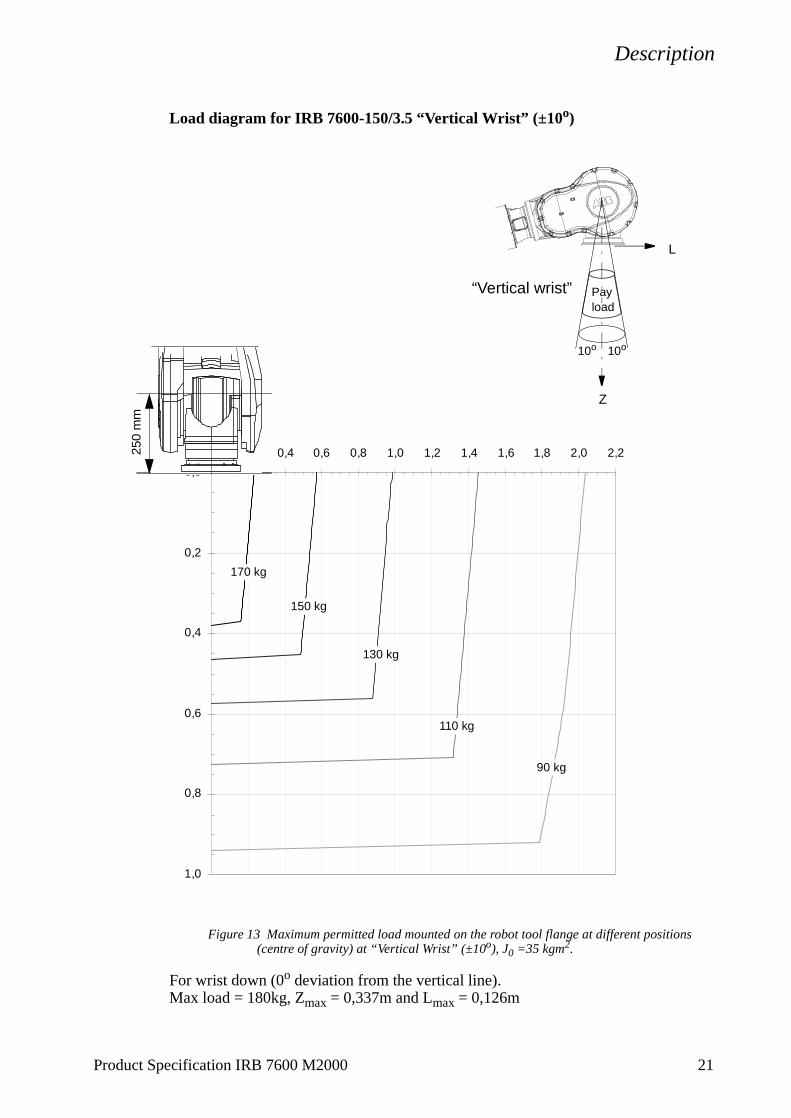
Load diagram for IRB 7600-150/3.5 “Vertical Wrist” (±10o)
Figure 13 Maximum permitted load mounted on the robot tool flange at different positions (centre of gravity) at “Vertical Wrist” (±10o), J0 =35 kgm2.
For wrist down (0o deviation from the vertical line). Max load = 180kg, Zmax = 0,337m and Lmax = 0,126m
0,0
0,2
0,4
0,6
0,8
1,0
0,0 0,2 0,4 0,6 0,8 1,0 1,2 1,4 1,6 1,8 2,0 2,2
Payload
10o 10o
Z
L
“Vertical wrist”
250
mm
150 kg
170 kg
130 kg
110 kg
90 kg
Product Specification IRB 7600 M2000 21

Description
22 Product Specification IRB 7600 M2000
Maximum load and moment of inertia for full and limited axis 5 (centre line down) movement.
Note. Load in kg, Z and L in m and J in kgm2
Full movement of axis 5 (±120o):
Axis 5Maximum moment of inertia:Ja5 = Mass • ((Z+0.250)2 +L2) + max J0L ≤ 500 kgm2
Axis 6Maximum moment of inertia:Ja6 = Mass • L2 + J0Z ≤ 315 kgm2
Figure 14 Own moment of inertia.
Limited axis 5, centre line down:
Axis 5Maximum moment of inertia:Ja5 = Load • ((Z+0.250)2 +L2) + J0L ≤ 550 kgm2
Axis 6Maximum moment of inertia:Ja6 = Load • L2 + J0Z ≤ 500 kgm2
Figure 15 Moment of inertia when axis 5 centre line down.
Z
XCentre of gravityJ0L = Maximum own moment of inertia
around the maximum vector in the X-Y-planeJ0Z = Maximum own moment of inertia around Z
J0Z = Maximum own moment of inertia around Z
Z
X
Centre of gravityJ0L = Maximum own moment of inertia
around the maximum vector in the X-Y-plane

Description
Mounting equipment
Extra loads can be mounted on the upper arm housing, the lower arm, and on the frame. Definitions of distances and masses are shown in Figure 16 and Figure 17.The robot is supplied with holes for mounting extra equipment (see Figure 18).Maximum permitted arm load depends on centre of gravity of arm load and robot payload.
Upper arm
Permitted extra load on upper arm housing plus the maximum handling weight (See Figure 16):M1 ≤50 kg with distance a ≤500 mm, centre of gravity in axis 3 extension.
/
Figure 16 Permitted extra load on upper arm.
Frame (Hip Load)
Permitted extra load on frame is JH = 200 kgm2.Recommended position (see Figure 17).JH = JH0 + M4 • R2
where JH0 is the moment of inertia of the equipmentR is the radius (m) from the centre of axis 1 M4 is the total mass (kg) of the equipment including
bracket and harness (≤500 kg)
Figure 17 Extra load on the frame of IRB 7600 (dimensions in mm).
Mounting of hip load
The extra load can be mounted on the frame. Holes for mounting see Figure 20.When mounting on the frame all the four holes (2x2, ∅ 16) on one side must be used.
806 2507600-500/2.3
Masscentre
a
M1
M1
600
View from above
View from the rear
View from above View from the rear
200
600
543
473
1180
800
Product Specification IRB 7600 M2000 23

Description
Holes for mounting extra equipment
Figure 18 Holes for mounting extra equipment on the upper and the lower arm (dimensions in mm).
150
M12 (4x)
2512,5
780
1075
165
250
50
100
477
M12 (4x)
0
777
806(1056)(2012)
24 Product Specification IRB 7600 M2000

Description
Product Specification IRB 7600 M2000 25
Figure 19 Holes for mounting of extra load on the upper arm (dimensions in mm).
Figure 20 Holes for mounting of extra load on the frame, and for mounting of fork lift device (dimensions in mm).
240
M16 (4x)
290290 240
60
50
M16 (4x)

Description
Figure 21 The mechanical interface; mounting flange (dimensions in mm).
12 H7 Depth 15
12 H7 Depth 15
A
12 x1,6
0,04 A
0,2 A B
0,04 A
B
200
15
12x
30
1,6
31
0,02 A
A
A
5
(24)
A - A
26 Product Specification IRB 7600 M2000

Description
Product Specification IRB 7600 M2000 27
1.5 Maintenance and Troubleshooting
The robot requires only a minimum of maintenance during operation. It has been designed to make it as easy to service as possible:
- Maintenance-free AC motors are used.
- Liquid grease or oil is used for the gear boxes.
- The cabling is routed for longevity, and in the unlikely event of a failure, its modular design makes it easy to change.
The following maintenance is required:
- Changing filter for the transformer/drive unit cooling every year.
- Changing batteries every third year.
The maintenance intervals depend on the use of the robot. For detailed information on maintenance procedures, see Maintenance section in the Product Manual.

Description
1.6 Robot Motion
Type of motion Range of movement
Axis 1 Rotation motion +180oto-180o Axis 2 Arm motion +85oto-60o Axis 3 Arm motion +60oto-180o
Axis 4 Wrist motion +300oto-300o Axis 5 Bend motion +100oto-100o Axis 6 Turn motion +300oto -300o
Figure 22 The extreme positions of the robot arm specified at the wrist centre (dimensions in mm).
IRB 7600-500/2.3
28 Product Specification IRB 7600 M2000

Description
Figure 23 The extreme positions of the robot arm specified at the wrist centre (dimensions in mm).
IRB 7600-400/2.55
IRB 7600-150/3.5
Product Specification IRB 7600 M2000 29

Description
30 Product Specification IRB 7600 M2000
Velocity
Maximum axis speeds.
IRB 7600 -400/2.55 -500/2.3 -150/3.5Axis no.
1 75°/s 75°/s 100°/s2 60°/s 60°/s 60°/s3 60°/s 60°/s 60°/s4 100°/s 100°/s 100°/s5 100°/s 100°/s 100°/s6 160°/s 160°/s 160°/s
Accuracy according to ISO 9283
Position accuracy: 0.10 mm (IRB 7600-400/2.55)Position repeatability: 0.19 mm (IRB 7600-400/2.55)Path repeatability: 1.27 mm (IRB 7600-400/2.55)
1.7 Cooling fan for axis 1-3 motor (options 113-115)
A motor of the robot needs a fan to avoid overheating if the average speed over time exceeds the value given in Table 1. The maximum allowed average speed is depending on the load.
The average speed can be calculated with the following formula:
The maximum allowed average speed depends on the ambient temperature according to Table 1 and can be interpolated linearly between 40-50oC.IP 54 for cooling fan.
Table 1
Variant Maximum ambient temp. (oC)
Maximum average speed axis 1 (rpm)
Maximum average speed axis 2 (rpm)
Maximum average speed axis 3 (rpm)
IRB 7600-500/2.3
4050
7.6 - 9.95.4 - 7.0
2.2 - 2.41.4 - 1.5
2.9 - 3.81.2 - 1.6
IRB 7600-400/2.55
4050
7.6 - 9.95.4 - 7.0
2.2 - 2.41.4 - 1.5
2.9 - 3.81.2 - 1.6
IRB 7600-150/3.5
4050
5.0 - 6.54.1 - 5.3
2.5 - 2.81.3 - 1.4
3.7 - 4.82.2 - 2.9
Average speed = Total axis movement, number of degrees, in one cycle
360 x cycle time (minutes) incl. waiting time

Description
1.8 DressPack for Material Handling
DressPack options
Dress Pack options include options for Upper arm harness, Lower arm harness and Floor harness. These are described separately below but are designed and meant to be seen as a complete package for either Material handling or Spot welding application.
The Upper Arm Harness consists of a process cable package and supports, clamps, brackets, and a retractor arm. The process cable package contains special designed cables and hoses that have been long term tested. The cables and hoses are partly placed in a protective hose to extend the lifetime.
The Upper Arm Harness is designed to follow the robot arm movements and minimise damages to the harness or the manipulator. The interface to the lower arm harness is located well protected below the motor for axis 3.
The complete harness is tested and proven to be well suited for both spot welding applications and other applications with the same type of movements and very high requirements. The cable and hose package has a 1000-mm free length at axis 6 for connection to a robot tool. A tension arm unit keeps hose package in the right position for the robot arm movement approved for the DressPack. An arm protection will prevent wearing on the protective hose and on the robot itself. Please note that when the robot is operating, some multiply axis movement might end up with an overstraining of the hose package. These movements must be avoided.
For more information see the Installation and Maintenance Manual.
Figure 24 Mechanical equipment upper arm harness.
Note. The upper arm harness specification is based on the selection of lower arm harness.
The Lower Arm Harness consists of a process cable package and supports, clamps and brackets. The process cable package, containing special designed cables and hoses, has been long term tested.
Process Cable package
Tension arm unit
Arm protection
Harness support axis 6
Option 2205
Product Specification IRB 7600 M2000 31

Description
The process cable package is routed along the lower arm to minimize space required and to give no limitation in the robot working envelope. The cables and hoses are partly placed in a protective hose to extend the lifetime.
The lower arm harness is connected to the upper arm harness at the connection point under the axis 3 motor. The interface plate at the manipulator base is the place where the floor harness and the process media are connected.
The Floor Harness consists of signal cables for customer signals. The floor harness is connected to the lower arm harness at the interface plate at the manipulator base and to the left side of the control cabinet. The signal connection inside the control cabinet depends on chosen options. As example bus option and parallel option mean different connections.
The cables and hose which are used to form the DressPack for the Material Handling application has the following specification and capacity:
* Quad twisted under separate screen. Can also be used for very sensitive signals
Process cable package
For material handling the DressPack can be chosen in different configurations, where details of the signals and media are added.
Option 056 Connection to manipulator
No floor cables for the DressPack are chosen. The connector at the base for interfacing is specified in the installation and maintenance manual. Terminal connections could be found in the circuit diagrams.
Table 2
Type Pcs Area Allowed capacity
Customer Power (CP)Utility PowerProtective Earth
2+21
0,5 mm2
1,0 mm2500 VAC, 5 A rms500 VAC
Customer Signals (CS)Signals twisted pairSignals twisted pair and separate shielded
194
0,23 mm2
0,23 mm250 VAC/DC, 1 A rms50 VAC/DC, 1 A rms
Customer Bus (CBus)Bus signalsBus signalsBus signalsBus utility signals
2244
0,18 mm2
0,18 mm2
0,18 mm2
0,23 mm2
Profibus 12 Mbit/s spec*Can/DeviceNet spec*Interbus spec*50 VAC/DC, 1 A rms
MediaAir (PROC 1) 1 12,5 mm
inner diameter
Max. pressure 16 bar / 230 PSI
32 Product Specification IRB 7600 M2000

Description
Option 057 Connection to cabinet
Floor cables for the DressPack are chosen. The number of cables and cable type depends on chosen options. The length of the process cable package at the floor is specified under the options below:
- Option 675-678 for parallel communication
- Option 660-663 for bus communication with CANDeviceNet
- Option 665-668 for bus communication with Profibus
- Option 670-673 for bus communication with Interbus
The connection inside the cabinet depends on communication type.
- If parallel communication is chosen, signals are found at terminals inside the cabinet (XT5.1, XT5.2 and XT6)
- If bus communication is chosen, signals are both routed to valid bus card. The remaining are found at terminals inside the cabinet (XT5.1, XT5.2 and XT6).
Communication
Option 2063 Parallel communication
The process cable package has been chosen for parallel communication. The number as well as the type of signals are defined under Material handling application, Option 2204, 2205.
Option 2064 Bus communication
The process cable package has been chosen for bus communication. This alternative includes both the signals for the bus communication as well as some parallel signals. The number as well as the type of signals are defined under Material handling application, Option 2204, 2205. The type of bus is defined by the choice of floor cabling (see also option 057)
Option 2204 Material Handling axis 1 to axis 3
The Lower arm harness for the Material Handling has been chosen. This includes the process cable package as well as brackets, connectors etc. to form a complete dressing package from manipulator base to connectors on axis 3. Depending on the choice above the process cable package will have different content. See tables below.
For all process cable packages some of the content are common. These common parts for Material Handling application are shown in Table 3 below. Unique parts for different option combinations are shown in Table 4, Table 5 and Table 6. These tables are valid for option 2204 and 2205.
Product Specification IRB 7600 M2000 33

Description
Figure 25 Material Handling from foot to axis 3
Table for Common content Material Handling (with option 2063/2064)
Table for Material Handling with option 2063
* Terminals inside the cabinet if option 057 is chosen** At manipulator base or axis 3 interface (or axis 6 under option 2205)
Table 3
Type Pieces at Connection point
Note Allowed capacity
Media
Air (PROC 1) 1 12,5 m inner diameter
Max pressure 16 bar / 230 PSI
Table 4
Type Pieces at Terminal*
Pieces at Connection point**
Allowed capacity
Customer Power (CP)Utility PowerProtective earth
2+21
2+21
500 VAC, 5 A rms500 VAC
Customer Signals (CS)Signals twisted pairSignals twisted pair and separate shielded
194
194
50 VAC, 5 A rms50 VAC, 5 A rms
option 2204
34 Product Specification IRB 7600 M2000

Description
Table for Material Handling with option 2064 and Can/DeviceNet
* Terminals inside the cabinet if option 057 is chosen** At manipulator base or axis 3 interface (or axis 6 under option 2205)
Table for Material Handling with option 2064 and Interbus
* Terminals inside the cabinet if option 057 is chosen** At manipulator base or axis 3 interface (or axis 6 under option 2205)
Option 2205 Material Handling axis 3 to axis 6
The Upper arm harness for the Material Handling has been chosen. This includes the process cable package as well as brackets, connectors etc. to form a complete dressing package from interface at axis 3 to the connectors at axis 6. Depending on the earlier choice (see option 2204) the process cable package will have different content. For content see Table 3, Table 4, Table 5 and Table 6. See also Figure 24.
The connector type at the manipulator base, at axis 3 and axis 6 is specified in the installation and maintenance manual.
Table 5
Type Pieces at Terminal*
Pieces at Connection point**
Allowed capacity
Customer Power (CP)Utility PowerProtective earth
2+21
2+21
500 VAC, 5 A rms500 VAC
Customer Bus (CBus)Bus signalsBus signalsSignals twisted pairUtility signals
44
2244
Can/DeviceNet spec50 VAC, 1 A rms50 VAC, 1 A rms50 VAC, 1 A rms
Table 6
Type Pieces at Terminal*
Pieces at Connection point**
Allowed capacity
Customer Power (CP)Utility PowerProtective earth
2+21
2+21
500 VAC, 5 A rms500 VAC
Customer Bus (CBus)Bus signalsBus signalsSignals twisted pairUtility signals
43
4143
Interbus spec50 VAC, 1 A rms50 VAC, 1 A rms50 VAC, 1 A rms
Product Specification IRB 7600 M2000 35

Description
36 Product Specification IRB 7600 M2000

Specification of Variants and Options
2 Specification of Variants and Options
The different variants and options for the IRB 7600 are described below.The same numbers are used here as in the Specification form. For controller options, see Product Specification S4Cplus, for software options, see Product Specification RobotWare Options, and for SpotPack options, see Product Specification SpotPack.
1 MANIPULATOR
VARIANTS
021 IRB 7600-150/3.5024 IRB 7600-400/2.55025 IRB 7600-500/2.3
Manipulator colour
330 StandardThe manipulator is painted in ABB orange.
352 Ral codeColours according to RAL-codes. Not available for Foundry.
Protection
035 Standard (IP 67)
036 FoundryRobot adapted for foundry or other harsh environments.The robot has the FoundryPlus protection which means that the whole manipulator is IP67 classified and steam washable. An excellent corrosion protection is obtained by a special coating. The connectors are designed for severe environment, and bearings, gears and other sensitive parts are highly protected. Only available colour is ABB orange Foundry.
PROCESS CABLE PACKAGE
For more information see chapter 1.8 DressPack for Material Handling.Regarding DressPack for spot welding see Product Specification SpotPack.
2204 Material Handling from foot to axis 3Requires Communication Parallel or Bus option 2063/2064.See Figure 25, and chapter1.8 DressPack for Material Handling and Table 2 - Table 6.
2205 Material Handling from axis 3 to axis 6Requires Material Handling from foot to axis 3 option 2204 and Communication Parallel or Bus option 2063/2064.See Figure 25, and chapter1.8 DressPack for Material Handling and Table 2 - Table 6.
Product Specification IRB 7600 M2000 37

Specification of Variants and Options
38 Product Specification IRB 7600 M2000
Communication
2063 ParallelIncludes customer power CP, customer signals CS and Air for MH-process cable package.
2064 BusIncludes CP, Air and CAN/DeviceNet, Interbus or Profibus for MH-process cable package.
Figure 26 Location of MH connections on the foot.
Figure 27 Location of MH connections on axis 3.
R1.SW1 7th Axis R1.MP R1.SMB
R1.SW2/3 R1.PROC1
R1.CP/CS
1 x 1/2”
R2.CP/CS
R2.PROC1 1 x 1/2” R2.MP 5/6

Specification of Variants and Options
Connection to
056 ManipulatorThe signals are connected directly to the manipulator base to one heavy duty industrial housing with a Harting modular connector R1.CP/CS, see Figure 26. The cables from the manipulator base are not supplied.
057 CabinetThe signals CP/CS are connected to 12-pole screw terminals, Phoenix MSTB 2.5/12-ST-5.08, in the controller. The cable between R1.CP/CS and the controller is supplied. For information about the limited number of signals available, see DressPack options on page 31.
Connection to cabinet (Cable lengths)
Parallel/CANDeviceNet/Interbus/Profibus
675/660/670/665 7m676/661/671/666 15m678/663/673/668 30m
EQUIPMENT
691 Safety lampA safety lamp with an orange fixed light can be mounted on the manipulator.The lamp is active in MOTORS ON mode.The safety lamp is required on a UL/UR approved robot.
092 Fork lift deviceLifting device on the manipulator for fork-lift handling.Note. When Cooling Fan for axis 1 motor unit is used, this must be disassembled in order to use fork lift device.
087 Base plateSee chapter 1.3 Installation, for dimension drawing.
091 Brake release coverA cover for the break release buttons.
113 Cooling fan for axis 1 motor (IP 54)Cannot be combined with Cooling fan for axis 2 motor option 114.For in use recommendations see 1.7 Cooling fan for axis 1-3 motor (options 113-115).See Figure 28.Not for protection Foundry.
114 Cooling fan for axis 2 motor (IP 54)For in use recommendations see 1.7 Cooling fan for axis 1-3 motor (options 113-115).Not for protection Foundry.
115 Cooling fan for axis 3 motor (IP 54)For in use recommendations see 1.7 Cooling fan for axis 1-3 motor (options 113-115).See Figure 28.Not for protection Foundry.
Product Specification IRB 7600 M2000 39

Specification of Variants and Options
40 Product Specification IRB 7600 M2000
088 Upper arm coversSee Figure 29.
Figure 28 Cooling fan for axis 1 motor and axis 3 motor.
Figure 29 Upper arm covers.
1300 Axis 1 coverA leather cover around the cables in the central hole at axis 1.
1301 Piston coverA leather bellow for the balancing cylinder piston.
POSITION SWITCHES
Position switches indicating the position of the three main axes. Rails with separate adjustable cams are attached to the manipulator. The cams, which have to be adapted to the switch function by the user, can be mounted in any position in the working range for each switch. No machining operation of the cams is necessary for the adaptation, simple hand tools can be used.
For axis 1, there are three redundant position zones available, each with two independent
Option 115
Option 113
Option 088

Specification of Variants and Options
switches and cams. For axes 2 and 3, two redundant position zones are available, each with two independent switches and cams.
For axis 1 it is possible to mount a second set of position switches, doubling the number of redundant zones to six.Each position zone consists of two switches mechanically operated by separate cams. Each switch has one normally open and one normally closed contact. See Product Specification S4Cplus.The design and components fulfil the demands to be used as safety switches.These options may require external safety arrangements, e.g. light curtains, photocells or contact mats.
The switches can be connected either to the manipulator base (R1.SW1 and R1.SW2/3, see Figure 26), or to the controller. In the controller the signals are connected to screw terminal XT8 Phoenix MSTB 2.5/12-ST-5.08. Switch type Balluff Multiple position switches BNS, according to EN 60947-5-1 and EN 60947-5-2.
Connection to075 Manipulator
Connection on the manipulator base with one/two FCI Sealok 32-pin connector.076 Cabinet
Connected to 12-pole screw terminals, Phoenix MSTB 2.5/12-ST-5.08, in the controller. Position switch cables are included.
Position switches axis 1071 Three redundant position zones are available, each with two independent switches and
cams.
Connection of signals axis 1 (cable lengths)078 7m079 15m081 30m
072 Position switches axis 2Two redundant position zones are available, each with two independent switches and cams.
073 Position switches axis 3Two redundant position zones are available, each with two independent switches and cams.
Connection of signals axes 2 and 3 (cable lengths)083 7m084 15m086 30m
WORKING RANGE LIMIT
To increase the safety of the robot, the working range of axes 1, 2 and 3 can be restricted by extra mechanical stops.
Product Specification IRB 7600 M2000 41

Specification of Variants and Options
Axis 1061 Four stops which allow the working range to be restricted in increments of 7,5o.
062 Two stops which allow the working range to be restricted in increments of 15o.
063 Axis 2Six stops which allow the working range to be restricted in increments of 15o at both end positions. Each stop decreases the motion by 15o.
064 Axis 3Six stops which allow the working range to be restricted in increments of 20o at both end positions. Each stop decreases the motion by 20o.
42 Product Specification IRB 7600 M2000

Accessories
3 Accessories
There is a range of tools and equipment available, specially designed for the robot.
Basic software and software options for robot and PC
For more information, see Product Specification S4Cplus, and Product Specification RobotWare Options.
Robot Peripherals
- Track Motion
- Tool System
- Motor Units
- Spot welding system for transformer gun
Tools
Brake release box Includes six brake release buttons and 24V battery unit which can be connected to R1.BU on the manipulator frame. The brake release box can be ordered from ABB Automation Technology Products AB, Robotics, department S.
Calibration CubeThis calibration tool can be ordered from ABB Automation Technology Products AB, Robotics, department S.
Product Specification IRB 7600 M2000 43

Accessories
44 Product Specification IRB 7600 M2000

Index
4 Index
A
accessories 43Active Brake System 8Active Safety System 7
C
Collision detection 8colours 37cooling device 4
E
Electronically Stabilised Path 8emergency stop 9enabling device 9equipment
mounting 23permitted extra load 23
F
fire safety 10fork lift device 39
H
hold-to-run control 10hole configuration 12holes for mounting extra equipment 24humidity 11
I
installation 11Internal Safety Concept 9
L
lifting device 39load 11load diagrams 15
M
maintenance 27manipulator colour 37mechanical interface 26
Product Specification IRB 7600 M2000
motion 28mounting
extra equipment 23robot 11
mounting flange 26
N
noise level 4
O
operating requirements 11options 37overspeed protection 8
P
Passive Safety System 8payload 11performance 30position switches 40protection 37protection standards 11
R
range of movement 28reduced speed 9Robot Peripherals 43robot versions 4
S
safeguarded space stop 10delayed 10
safety 7Safety category 3 9safety lamp 10, 39Self Tuning Performance 8service 27Service Information System 7space requirements 4standards 7structure 3
T
temperature 11troubleshooting 27
45

Index
4
V
variants 37
W
weight 4working space
restricting 8, 11, 41
Z
zone switches 9
6
Product Specification IRB 7600 M2000


