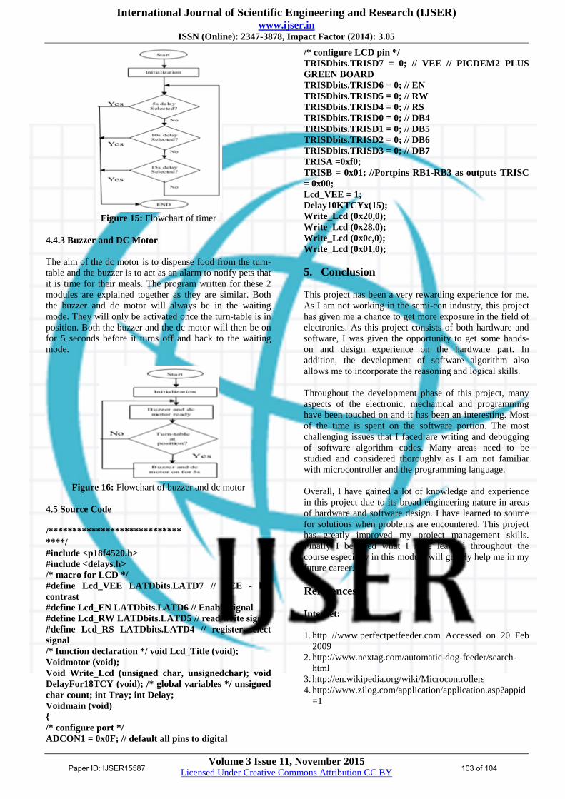
International Journal of Scientific Engineering and Research (IJSER) www.ijser.in ISSN (Online): 2347-3878, Impact Factor (2014): 3.05 Volume 3 Issue 11, November 2015 Licensed Under Creative Commons Attribution CC BY Programmable Pet Feeder Tessema Gelila Berhan 1 , Worku Toyiba Ahemed 2 , Tessema Zelalem Birhan 3 Tianjin University of Technology and Education (TUTE), School of Electronics Engineering, Tianjin, 300222, P.R.CHINA Abstract: Over the years, more and more households are beginning to have pets. Pet feeders came into existence as more and more pet owners found it difficult to cater time to feed their pets. Pet feeders are automated machines that dispense food at preset schedule. They are mainly timed based and dispense a certain amount of food at specific time of the day. The pet feeder is a programmable system which is mainly controlled by a microcontroller. It consists of a LCD screen for input display, buzzer to alert pets for meals, stepper motor to control the speed and a turn table which is divided into different sections for placement of different food. User will be able to select the food to be dispensed out at their desired timing. Keywords: Turn-table, PIC18F4520 microcontroller, Buzzer Stepper Motor, DC motor 1. Introduction 1.1 Background Pet feeding can be difficult in this busy age but the perfect Pet feeder delivers a worry free solution to modern, caring pet-parents while away. There are many various types of automated pet feeding devices in the market now. Generally most pet feeders are commonly for cats and dogs but for a few special cases, some pet feeders for instances, like the fish pet-feeder or the hamster pet feeder are specifically designed to suit only for that particular type of pet due to their size and environmental living conditions. 1.2 Overview The design of the programmable pet feeder can be broken down into 2 stages. The first stage is the construction of individual components and the second stage involves interfacing the components with the goal of operating as one unit. During the construction stage, the components can be categorized as either hardware or software. The basic hardware components consist of microcontroller, LCD, buzzer and motors. The basic software component consists of a motor control algorithm and a delay timer algorithm. User will input data on the LCD and the 40 pin microcontroller which is the brain of the pet feeder will perform motor control and delay algorithms. 2. Objective There are some objective needs to be archived in order to accomplish this project. But the main objective of the project is to design a programmable system which is able to (I) Serve food for pets at programmable times (ii) Enhance the performance and stability of the system. (iii) Develop the system that works automatically. The project shall adopt the Structured System Analysis and Design methodology approach to achieve the project objective. Figure 1: Block diagram of pet feeder system The system will consist of the following modules: 1. Power supply to supply voltages to each modules 2. Microcontroller for programming and controlling 3. Buzzer for alerting pets 4. Stepper Motors to control the speed and positioning 5. Turn table to rotate at programmable time 6. LCD (Liquid Crystal Display) 3. Hardware System Hardware Implementation 1. Micro-controller- programming and controlling 2. Power Supply- supply voltages 3. Stepper motor- to control the speed and positioning 4. Turn-Table- to rotate at programmable time 5. DC motor-to dispense food Buzzer-sound for alerting 3.1 Microchip Microcontroller (18F Series) This family offers the advantages of all PIC18microcontrollers mainly: High computational performance at an economical price with addition of high endurance Enhanced Flash program memory Design enhancements for many high- performances, power sensitive applications. 3.1.1 PIC18F4520 The microchip PIC18F4520 microcontroller is a 40 pin 8 bit processor with five ports available to be used depending on the device selected and features enabled. Some pins of the I/O ports are multiplexed with an alternate function from the peripheral features on the Paper ID: IJSER15587 99 of 104
Transcript
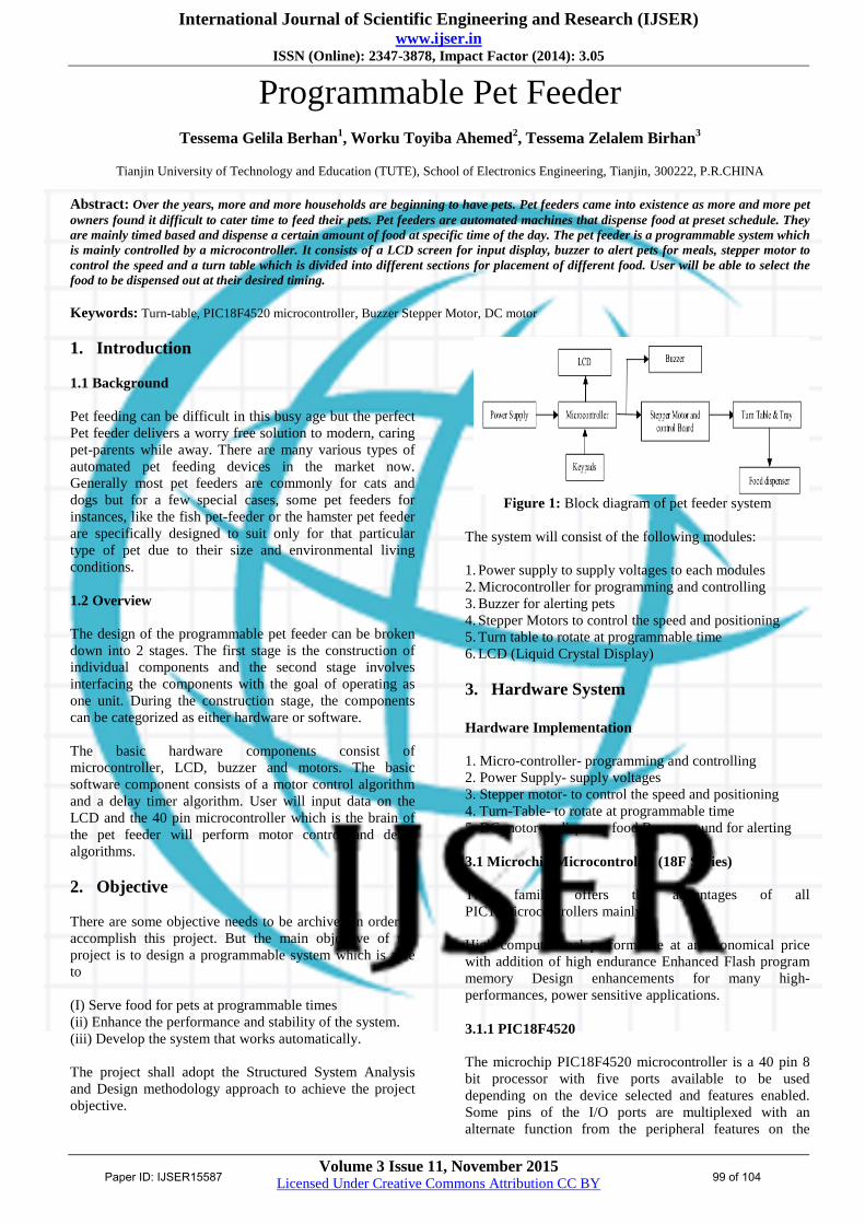
International Journal of Scientific Engineering and Research (IJSER) www.ijser.in