CONFIDENTIAL PDB.DR142.fs.13_D6.1_DRAFT 02/12/13 PDB.DR142.fs.13_D6.1_DRAFT WP6/DELIVERABLE NUMBER D6.1 02/12/13 PROJECT DELIVERABLE REPORT Grant Agreement Number: 260153 Project Acronym: QCOALA Project Title: Quality Control of Aluminium Laser-welded Assemblies Funding Scheme: FoF.ICT.2010.10-1 Seventh Framework Programme Date of latest version of Annex I against which the assessment will be made: 18 May 2010 Deliverable Number and Title: D6.1 Demo of PV Cells Name, title and organisation of the scientific representative of the project's coordinator 1 : Paola De Bono Senior Project Leader Specialist Materials and Joining Sector Advanced Materials and Processes Group TWI Ltd Granta Park, Great Abington, Cambridge CB21 6AL United Kingdom F: +44 (0)1223 892588 W: www.twi.co.uk Tel: +44 (0)1223 899530 Direct E-mail: [email protected]Project website 2 address: www.qcoala.eu QCOALA Project Document Reference: PDB.DR142.fs.13_D6.1DRAFT Author(s): 1 Usually the contact person of the coordinator as specified in Art.1 of the grant agreement. 2 The home page of the website should contain the generic European flag and the FP7 logo which are available in electronic format at the Europa website (logo of the European flag: http://europa.eu/abc/symbols/emblem/index_en.htm ; logo of the 7th FP: http://ec.europa.eu/research/fp7/index_en.cfm?pg=logos). The area of activity of the project should also be mentioned.
Transcript
CONFIDENTIAL PDB.DR142.fs.13_D6.1_DRAFT
02/12/13
PDB.DR142.fs.13_D6.1_DRAFT WP6/DELIVERABLE NUMBER D6.1 02/12/13
PROJECT DELIVERABLE REPORT Grant Agreement Number: 260153
Project Acronym: QCOALA
Project Title: Quality Control of Aluminium Laser-welded Assemblies
Date of latest version of Annex I against which the assessment will be made:
18 May 2010
Deliverable Number and Title: D6.1 Demo of PV Cells
Name, title and organisation of the scientific representative of the project's coordinator
1:
Paola De Bono Senior Project Leader Specialist Materials and Joining Sector Advanced Materials and Processes Group TWI Ltd Granta Park, Great Abington, Cambridge CB21 6AL United Kingdom F: +44 (0)1223 892588 W: www.twi.co.uk
1 Usually the contact person of the coordinator as specified in Art.1 of the grant agreement.
2 The home page of the website should contain the generic European flag and the FP7 logo which are
available in electronic format at the Europa website (logo of the European flag: http://europa.eu/abc/symbols/emblem/index_en.htm ; logo of the 7th FP: http://ec.europa.eu/research/fp7/index_en.cfm?pg=logos). The area of activity of the project should also be mentioned.
PDB.DR142.fs.13_D6.1_DRAFT WP…/DELIVERABLE NUMBER D6.1 02/12/13
1
1 Introduction
The demonstration of the integrated system for the photovoltaics application is essence a major objective of the QCOALA project. It brings together all parts of work in this area of the project starting with the definition of the end user requirements (WP1), the developed laser system (WP2), the collected experiences of intelligent laser welding (WP3), the process monitoring system (WP4) and finally the weld inspection system (WP5). All this has been assembled in the facilities of Ruhr-University Bochum for the demonstration activity. This deliverable report describes the work performed under the headings of: the Welding Platform, the Weld Monitoring System and the Radiographic Inspection system.
2 Welding Platform
2.1 Equipment
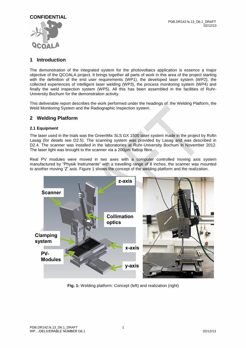
The laser used in the trials was the GreenMix SLS GX 1500 laser system made in the project by Rofin Lasag (for details see D2.5). The scanning system was provided by Lasag and was described in D2.4. The scanner was installed in the laboratories at Ruhr-University Bochum in November 2012. The laser light was brought to the scanner via a 200µm flattop fibre. Real PV modules were moved in two axes with a computer controlled moving axis system manufactured by “Physik Instrumente” with a travelling range of 8 inches, the scanner was mounted to another moving ‘Z’ axis. Figure 1 shows the concept of the welding platform and the realization.
Fig. 1: Welding platform: Concept (left) and realization (right)
CONFIDENTIAL PDB.DR142.fs.13_D6.1_DRAFT
02/12/13
PDB.DR142.fs.13_D6.1_DRAFT WP…/DELIVERABLE NUMBER D6.1 02/12/13
2
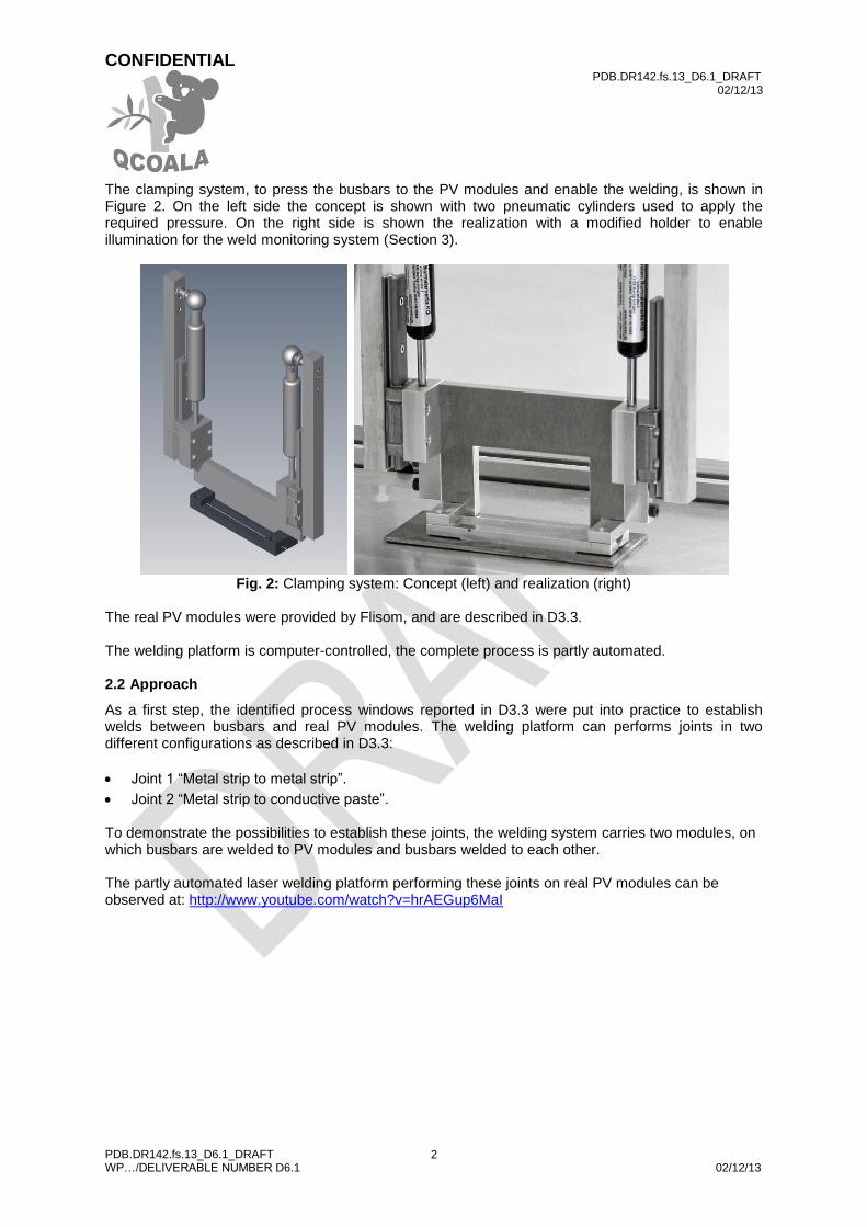
The clamping system, to press the busbars to the PV modules and enable the welding, is shown in Figure 2. On the left side the concept is shown with two pneumatic cylinders used to apply the required pressure. On the right side is shown the realization with a modified holder to enable illumination for the weld monitoring system (Section 3).
Fig. 2: Clamping system: Concept (left) and realization (right)
The real PV modules were provided by Flisom, and are described in D3.3. The welding platform is computer-controlled, the complete process is partly automated. 2.2 Approach
As a first step, the identified process windows reported in D3.3 were put into practice to establish welds between busbars and real PV modules. The welding platform can performs joints in two different configurations as described in D3.3:
Joint 1 “Metal strip to metal strip”.
Joint 2 “Metal strip to conductive paste”.
To demonstrate the possibilities to establish these joints, the welding system carries two modules, on which busbars are welded to PV modules and busbars welded to each other. The partly automated laser welding platform performing these joints on real PV modules can be observed at: http://www.youtube.com/watch?v=hrAEGup6MaI
PDB.DR142.fs.13_D6.1_DRAFT WP…/DELIVERABLE NUMBER D6.1 02/12/13
3
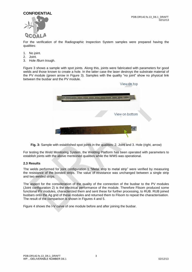
For the verification of the Radiographic Inspection System samples were prepared having the qualities: 1. No joint. 2. Joint. 3. Hole /Burn trough. Figure 3 shows a sample with spot joints. Along this, joints were fabricated with parameters for good welds and those known to create a hole. In the latter case the laser destroys the substrate material of the PV module (green arrow in Figure 3). Samples with the quality “no joint” show no physical link between the busbar and the PV module.
Fig. 3: Sample with established spot joints in the qualities: 2. Joint and 3. Hole (right, arrow)
For testing the Weld Monitoring System, the Welding Platform has been operated with parameters to establish joints with the above mentioned qualities while the WMS was operational. 2.3 Results
The welds performed for joint configuration 1 “Metal strip to metal strip” were verified by measuring the resistance of the bonded strips. The value of resistance was unchanged between a single strip and two welded strips. The aspect for the consideration of the quality of the connection of the busbar to the PV modules (Joint configuration 2) is the electrical performance of the module. Therefore Flisom produced some functional PV modules, characterized them and sent these for further processing, to RUB. RUB joined busbars onto the Ag grid of these modules and returned them to Flisom to repeat the characterisation. The result of the comparison is shown in Figures 4 and 5. Figure 4 shows the I-V curve of one module before and after joining the busbar.
CONFIDENTIAL PDB.DR142.fs.13_D6.1_DRAFT
02/12/13
PDB.DR142.fs.13_D6.1_DRAFT WP…/DELIVERABLE NUMBER D6.1 02/12/13
4
Fig. 4: I-V curve with and without joined busbar
Figure 5 shows the series resistance and the module efficiency, with and without the joined busbar respectively.
Fig. 5: Series resistance and module efficiency of
several tests: PV module with and without busbars. The results of using the Weld Monitoring System and the Radiographic Inspection System are reported following a discussion of the above results. 2.4 Discussion
The welding platform produces welds of good quality for both joint configurations. Results are reported in D3.3. Additional tests were made with the demo welded PV modules. Figure 4 shows the I-V curve measured at Flisom in the sun simulator. The resulting series resistance and the efficiency of the PV modules are shown in Figure 5. Nearly every module showed that the application of the busbars had no influence on their electrical behaviour. Just one module showed a reduced efficiency of approximately 25%. A possible reason for this might be disruptions due to handling of the module and return shipping. There are a lot of steps in the production, packaging, shipping and treatment of the module, so a failure arising from this is a possibility.
CONFIDENTIAL PDB.DR142.fs.13_D6.1_DRAFT
02/12/13
PDB.DR142.fs.13_D6.1_DRAFT WP…/DELIVERABLE NUMBER D6.1 02/12/13
5
It is very clear that this method of welding produces limited mechanical stability of the joint. The PV modules with welded busbars must be handled with a lot of care. Any full production system must take this into account. A closer look is needed to investigate bendability in repetitive use. It might be that additional actions are needed, e.g. the compensation of stability by encapsulating the module. 2.5 Summary and conclusions
Extensive trials were made to establish the connection of busbars to PV modules. A platform was built to transact the results in semi-automated operation. The PV modules treated using the welding platform were tested by the QCOALA partner Flisom. The reported methods for laser welding busbars to flexible CIGS solar modules and busbars to each other were successful. From an electrical conductivity point of view, this method is suitable. In general, it is felt operation in a production line is possible. 2.6 Recommendations
To increase the mechanical stability of the joints, it might be desirable to enlarge the welding area.
3 Weld Monitoring System
3.1 Equipment
Fig. 6: QCOALA demonstration platform showing scanner and weld monitoring system
The weld monitoring system, which can be seen in Figure 6, was integrated into the scanner system and tested by Fraunhofer-ILT.
CONFIDENTIAL PDB.DR142.fs.13_D6.1_DRAFT
02/12/13
PDB.DR142.fs.13_D6.1_DRAFT WP…/DELIVERABLE NUMBER D6.1 02/12/13
6
3.2 Approach
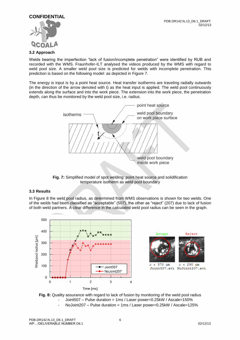
Welds bearing the imperfection “lack of fusion/incomplete penetration” were identified by RUB and recorded with the WMS. Fraunhofer-ILT analysed the videos produced by the WMS with regard to weld pool size. A smaller weld pool size is predicted for welds with incomplete penetration. This prediction is based on the following model: as depicted in Figure 7. The energy is input is by a point heat source. Heat transfer isotherms are traveling radially outwards (in the direction of the arrow denoted with t) as the heat input is applied. The weld pool continuously extends along the surface and into the work piece. The extension into the work piece, the penetration depth, can thus be monitored by the weld pool size, i.e. radius.
Fig. 7: Simplified model of spot welding: point heat source and solidification
temperature isotherm as weld pool boundary
3.3 Results
In Figure 8 the weld pool radius, as determined from WMS observations is shown for two welds. One of the welds had been classified as “acceptable” (507), the other as “reject” (207) due to lack of fusion of both weld partners. A clear difference in the calculated weld pool radius can be seen in the graph.
Fig. 8: Quality assurance with regard to lack of fusion by monitoring of the weld pool radius
PDB.DR142.fs.13_D6.1_DRAFT WP…/DELIVERABLE NUMBER D6.1 02/12/13
7
3.4 Summary and conclusions
Starting from a point heat source model of laser spot welding, contact of the joint partners has been monitored in real time by recording the weldpool surface and calculating the weld pool size. The effectiveness of the monitoring system was successfully demonstrated on welds with lack of fusion due to incomplete penetration.
3.5 Recommendations
The lack of fusion detection method requires at a minimum, one image before the process and one image after the process. Based on this high-frequency imaging and processing, a closed-loop control of the process should be possible, for example by means of keeping the laser beam on until a certain weld pool size is reached.
4 Radiographic Inspection system
4.1 Introduction
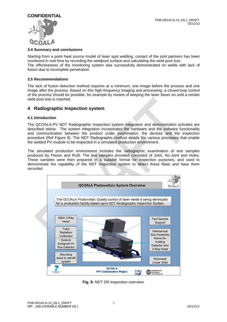
The QCOALA-PV NDT Radiographic Inspection system integration and demonstration activities are described below. The system integration incorporates the hardware and the software functionality and communication between the product under examination, the devices and the inspection procedure (Ref Figure 9). The NDT Radiographic method details the various processes that enable the welded PV module to be inspected in a simulated production environment. The simulated production environment includes the radiographic examination of test samples produced by Flisom and RUB. The test samples provided consisted of Joint, No-Joint and Holes. These samples were then prepared in a suitable format for inspection purposes, and used to demonstrate the capability of the NDT Inspection system to detect these flaws and have them recorded.
Fig. 9: NDT DR inspection overview.
CONFIDENTIAL PDB.DR142.fs.13_D6.1_DRAFT
02/12/13
PDB.DR142.fs.13_D6.1_DRAFT WP…/DELIVERABLE NUMBER D6.1 02/12/13
8
CITs NDT Radiographic Inspection system developed under the QCOALA project consisted of the data acquisition unit, data processing and data archival processes. The DR PV Demo contains the following set-ups and processes:
CONFIDENTIAL PDB.DR142.fs.13_D6.1_DRAFT
02/12/13
PDB.DR142.fs.13_D6.1_DRAFT WP…/DELIVERABLE NUMBER D6.1 02/12/13
9
Production batch instructions to the WMS and NDT inspection system.
Product definition data.
Product Radiographic technique.
Radiographic equipment parameters.
Radiographic image processing parameters.
Radiographic naming and data archiving.
Radiographic report generation and decision making.
NDT results transferred to the WMS. The linking of these processes to the rest of the PV application equipment can be seen in Figure 10.
Mechanical product handling
Fig. 10: QCOALA-PV Block Schematic
CONFIDENTIAL PDB.DR142.fs.13_D6.1_DRAFT
02/12/13
PDB.DR142.fs.13_D6.1_DRAFT WP…/DELIVERABLE NUMBER D6.1 02/12/13
10
4.2 Equipment
Radiographic Data Acquisition The mechanical sub-system consists of:
Product loading mechanism for PV Cells.
A motorised linear translation device with a travel of 0-450mm with a positional accuracy of +/- 25microns.
Radiographic image detector mounting arrangement.
Radiographic X-Ray head generator mounting arrangement.
Radiation shielding health and safety screening.
A mechanical mounting base for the entire assembly integrated to enable adaptability for installation on a production line.
Radiographic X-Ray system:
30kV – 80kV constant potential X-Ray generator unit.
33micron micro-focus focal spot.
10uA – 250uA current.
Computer controlled interface and safety warning.
Radiographic Detector:
Radiographic image area is 12mm x 8mm field of view.
Radiographic detector pixel size resolution of 4.7um.
Ability to generate image from 20kV – 80kV integrated with low-light solid state imaging device and intensifier.
Optical alignment of multiple devices to less than 10micron accuracy.
Computer integrated controls with USB connectivity.
Radiographic Radiation Shielding:
Radiation shielding for the X-Ray head generator unit to enable radiation leakage of less than 1uS at the surface of the unit.
Radiation cylindrical shielding for the X-Ray scatter controlled and a beam angle of 5 to cover a region of 15mm.
Additional radiation protection with the access restriction for intrusion.
Radiation assessment of leakage charts for information for demonstration.
QCOALA-PV NDT Radiographic software application V1.0 Microsoft windows based dedicated software inspection package.
The QCOALA-PV Input/output interface module
This module may be loaded onto the WMS system. For demo it will be demonstrated from a single workstation.
The module defines the product profiles, inspection techniques and the image processing parameters that are used during the data acquisition mode. These parameters are unique to each product under inspection. On the basis of these parameters the various automated processes are controlled and data captured, analysed and reports generated.
Auto/Manual control processing.
A separate section is the output module that enables the results of the inspection to be reviewed, browsed and inferences arrived at.
Product inspection acceptance tolerances definitions. These definitions are applied to the actual inspected images from which acceptance or rejection of that component is decided.
CONFIDENTIAL PDB.DR142.fs.13_D6.1_DRAFT
02/12/13
PDB.DR142.fs.13_D6.1_DRAFT WP…/DELIVERABLE NUMBER D6.1 02/12/13
11
QCOALA NDT Inspection Module
Current product profile and technique set-up.
Manual/Automatic capture of Radiographic images, display and processing. Pre-signal processing and conditioning for automated decision making.
Manual/Automatic control of X-Ray generator set-up and functions.
Manual/Automatic control of linear motion over the length of the laser welded PV panel.
Manual/Automatic mode of ADR (Automatic Defect Recognition) functions.
Transfer back of the inspected data to the input/output interface module.
System housekeeping
Product profile management, back-up and modification.
Product archive management.
4.3 Approach
The prepared test samples mounted on plastic sheets were used for setting up the inspection. The demonstration followed the procedure below: 1. Loading of the test samples onto the Radiographic data acquisition system. 2. Creation and selection of the product profile with the details of the product under examination. 3. Manual mode selection and demonstration of the NDT sub-system;
a. Demo of the X-Ray generator control system. b. Demo of the X-Ray detector control system. c. Demo of the manual drive positioning. d. Demo of the ADR – capture processing and display. e. Demo of the output results review and processing. f. Demo of the archived Radiographic images. g. Interface connectivity to the WMS under the situation if the package is loaded on the
central computer system. 4. Demo of the automatic mode data acquisition and processing.
4.4 Results
1. The demonstration illustrates the capability of the NDT Radiographic Inspection system to acquire images that can detect the thin-wall laser-welded PV Cell quality. This display is the proof of concept that can be optimised further by means of controlling the Radiographic parameters with more test samples that have known flaws.
2. From the test samples we have been able to detect the Joint, No-Joint and Hole classifications. Further assessment based on the diameters of the flaws can be made towards the weld integrity.
3. The radiation leakage tests concluded that the equipment can be operated in a production environment and can be installed within the laser welding facility.
4. The captured images can be further processed to detect the flaws and the sizes by means of using ADR. With the correct settings the ability to detect the flaws has been proven but is a complex process that needs to be developed over several production samples.
5. The Radiograph images archived can be browsed from which the quality controlled statistical information can be derived.
6. The demonstration also showed the integration of the various devices and interactions with the operator controls.
4.5 Discussion
1. Due to Solar PV module thin material and the complex weld geometry it has taken much longer time to establish the operating parameters. The weld geometry which consist of very low density material of PV film and the busbar, generates a very low SNR signal. This has taken more time for each sample to obtain am optimised image quality. This optimised image is to be used by ADR functions to detect flaws correctly. More experimental tests need to be carried out to provide the SNR from which flaws can be detected.
CONFIDENTIAL PDB.DR142.fs.13_D6.1_DRAFT
02/12/13
PDB.DR142.fs.13_D6.1_DRAFT WP…/DELIVERABLE NUMBER D6.1 02/12/13
12
2. There have been extensive hurdles during the software development integration, testing and de-bugging stages due to advanced image processing and Microsoft operating system change policies. This has consumed significant time to resolve and to change the hardware platforms to ensure compatibility and performance.
3. The integration of the real-time activities has resulted in multi-process synchronisation difficulties that have, at times have made the system software to become unstable. Measures to correct the instabilities have been an ongoing task which has proven to be time-consuming. This can further be optimised by much higher speed computing platforms to achieve the increased production speeds required.
4. The integration of the various Radiographic devices have been achieved and demonstrated. o
4.6 Summary and conclusions
1. The weld integrity can be distinguished with the inspection system through the application of ADR analysis. Full-scale capability of the various types of flaws, Joint, No-Joint and Holes has to be fully established with more test samples.
2. The inspection system is developed to examine 127mm to 450mm width Laser Welded Photovoltaic assemblies in the in-line production environment.
3. This production data is a part of the process for monitoring the laser-welded product quality. The inspection report generated will provide acceptance or rejection of the weld based upon the radiographic image and the various flaws that can be detected.
4. The detection decision is based upon the dimensional tolerances and shapes that have been detected in the image.
4.7 Recommendations
1) On the basis of the development of the QCOALA-PV NDT Digital Radiography Inspection technology it is practical to consider use of this system for inspection of solar panels.
2) The system as developed can be adapted to go into the in-line production inspection of the solar
panels with product inspection data being archived for process refinements. 3) The EC should consider additional add-on project where this system could be installed in a real
production environment. To ensure the laser-welded technology can be utilised to improve the product integrity over the lifespan of the components being used.
4) The QCOALA-PV NDT Radiographic Inspection system can also be applied to the inspection of
composite materials, thin wafer semi-conductors, medical devices and electronic components. 5) The above demo under the simulated conditions may need to be optimised and adapted to fulfil
the production speeds.
5 Demonstration
This part of the deliverable report will be inserted after the demonstration in RUB facilities at the 6th of
December. Aspects to be discussed in here:
Details of the overall integrated system with pictures.
Description of the necessary safety requirements, considering laser- and x-ray safety, with