Project Name: Indefinite Delivery of General Contracting Services Project Number: H27-D163-CA University of South Carolina Addendum One September 5, 2012 Clarifications All bids must be submitted no later than September 10, 2012 at 2:00 pm at 743 Greene Street, Columbia, South Carolina. If bids are going to be delivered other than hand delivery please give Juaquana Brookins a call to indicate the type of delivery the bid will be made, she can be reached at 803.777.3596. There will not be a unit pricing sheet for concrete per square feet included with the bidding documents, all unforeseen issues will be handled accordingly. Questions 1. Looking at the drawings are we to assume that everything is going to be stamped? Are the areas around the doors and entrances going to be saw-cut or stamped? What color(s) would you like them to be? All areas will be stamped concrete to the color of the owner’s choice. For all doors and columns will be a second color choice. 2. Is the lower level going to completely stamped or just the outlined “waved” areas? What color are the “waved” areas going to be? The lower level will be stamped with no waves. 3. If the lower level is going to be completely stamped is the pattern going to be the same throughout or are the “waved” areas going to vary from that? (Pattern Directions) No waves and the area will be stamped the same throughout.
Transcript
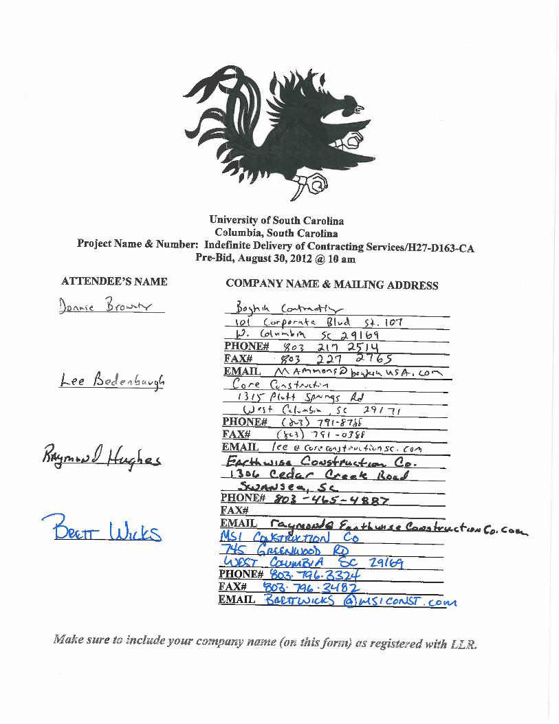
Project Name: Indefinite Delivery of General Contracting Services
Project Number: H27-D163-CA
University of South Carolina
Addendum One
September 5, 2012
Clarifications
All bids must be submitted no later than September 10, 2012 at 2:00 pm at 743 Greene Street,
Columbia, South Carolina.
If bids are going to be delivered other than hand delivery please give Juaquana Brookins a call to indicate
the type of delivery the bid will be made, she can be reached at 803.777.3596.
There will not be a unit pricing sheet for concrete per square feet included with the bidding documents,
all unforeseen issues will be handled accordingly.
Questions
1. Looking at the drawings are we to assume that everything is going to be stamped? Are the
areas around the doors and entrances going to be saw-cut or stamped? What color(s)
would you like them to be? All areas will be stamped concrete to the color of the owner’s
choice. For all doors and columns will be a second color choice.
2. Is the lower level going to completely stamped or just the outlined “waved” areas? What
color are the “waved” areas going to be? The lower level will be stamped with no waves.
3. If the lower level is going to be completely stamped is the pattern going to be the same
throughout or are the “waved” areas going to vary from that? (Pattern Directions) No
waves and the area will be stamped the same throughout.
4. What is the minimal thickness of the concrete that can be used per the manufactures
recommendations? The top elevations of the stamped concrete for the lower level shall
meet proposed grade shown in the civil plans. The top elevations of the stamped concrete
for the upper level shall match the existing grade. The contractor shall maintain a maximum
surface variance of plus or minus 1/8 inch in 10 feet in any direction.
5. Where can we clean out the concrete trucks? The roll off dumpster that you will provide.
Attachments:
Pre Bid Sign In Sheets
Revised Drawings
8" DOGWOOD
P
L
A
N
T
E
R
P
L
A
N
T
E
R
P
L
A
N
T
E
R
P
L
A
N
T
E
R
CONTROL POINT -
TACK IN CONC.
N:4999.28
E:4945.34
ELEV. =97.874
CONTROL POINT -
SCRIBE IN CONC.
N:5000.00
E:5000.00
ELEV. =100.000
CONTROL POINT -
TACK IN CONC.
N:4960.70
E:5039.30
ELEV. = 97.890
PROJECT CENTER POINT -
N:6523.12
E:2738.19
PROJECT RADIAL POINT -
N:6467.10
E:2682.21
SAWCUT AND REMOVE
EXIST. RETAINING WALLS
REMOVE EXIST. TREE
EXISTING GRATES TO BE ADJUSTED TO
ELEVATIONS SHOWN ON SHEET C2.0,
TYPICAL OF SIX(6)
TREE TO BE REMOVED
CONTRACTOR TO VERIFY THE
EXISTENCE OF IRRIGATION SYSTEM,
RELOCATE AS NECESSARY TO
ALLOW CONSTRUCTION OF
PROPOSED CONC. STEPS
4
.
6
5
'
REMOVE EXISTING TILE,
INSTALL STAMPED
CONCRETE
5
.
2
5
'
REMOVE EXISTING TILE, INSTALL
STAMPED CONCRETE
REMOVE EXISTING TILE, INSTALL
STAMPED CONCRETE
REMOVE EXISTING TILE,
INSTALL STAMPED
CONCRETE
4
.
6
5
'
4
.
6
5
'
THESE DOCUMENTS AND THE INFORMATION CONTAINED HEREIN ARE THE PROPERTY OF CHAO & ASSOCIATES, INC. AND MAY NOT BE USED FOR ANY PURPOSE WITHOUT THE WRITTEN PERMISSION OF CHAO & ASSOCIATES, INC.
Draw
n:
Sheet Number
File:
Checked:
Project N
o.:
Ch
ao
&
A
sso
cia
te
s, In
c.
Civil - S
tructural - S
urvey
7 C
lusters C
ourt
Colum
bia, S
C 29210
Voice: (803) 772-8420
Fax: (803) 772-9120
Em
ail: consult@
chaoinc.com
392233B
.dw
g
Revised:
C1.0
Existing C
onditions &
D
em
olition P
lan
US
C S
wearingen C
ourtyard
OS
E P
roject N
um
ber (H
27-N
273-C
A)
Prepared for: U
SC
F
acilities
Colum
bia, S
outh C
arolina
TK
SF
R
392233B
3 DAYS BEFORE DIGGING IN
SOUTH CAROLINA
Palmetto Utility Protection Service
Date
08/09/12
P
L
A
N
T
E
R
P
L
A
N
T
E
R
P
L
A
N
T
E
R
P
L
A
N
T
E
R
CONTROL POINT -
TACK IN CONC.
N:4999.28
E:4945.34
ELEV. =97.874
CONTROL POINT -
SCRIBE IN CONC.
N:5000.00
E:5000.00
ELEV. =100.000
CONTROL POINT -
TACK IN CONC.
N:4960.70
E:5039.30
ELEV. = 97.890
+
+
+
+
+
+
+
+
+
+
+
+
+
+
+
+
+
+
++
+
+
+
+
+
+
+
+
+
+
+
+
+
+
+
+
+
+
PROJECT CENTER POINT -
N:6523.12
E:2738.19
PROJECT RADIAL POINT -
N:6467.10
E:2682.21
NEW STEPS &
RETAINING WALLS, SEE
STRUCTURAL PLANS
FOR DETAILS
ADJUST GRATE
ELEVATION, TYP.
STAMPED CONCRETE
STAMPED CONCRETE
STAMPED CONCRETE
- FINISH GRADE ELEVATION
THESE DOCUMENTS AND THE INFORMATION CONTAINED HEREIN ARE THE PROPERTY OF CHAO & ASSOCIATES, INC. AND MAY NOT BE USED FOR ANY PURPOSE WITHOUT THE WRITTEN PERMISSION OF CHAO & ASSOCIATES, INC.
Draw
n:
Sheet Number
File:
Checked:
Project N
o.:
Ch
ao
&
A
sso
cia
te
s, In
c.
Civil - S
tructural - S
urvey
7 C
lusters C
ourt
Colum
bia, S
C 29210
Voice: (803) 772-8420
Fax: (803) 772-9120
Em
ail: consult@
chaoinc.com
392233B
.dw
g
Revised:
C2.0
Site G
rading P
lan
US
C S
wearingen C
ourtyard
OS
E P
roject N
um
ber (H
27-N
273-C
A)
Prepared for: U
SC
F
acilities
Colum
bia, S
outh C
arolina
TK
SF
R
392233B
3 DAYS BEFORE DIGGING IN
SOUTH CAROLINA
Palmetto Utility Protection Service
Date
08/09/12
1 9-5-12 R
EM
OV
ED
P
AT
TE
RN
S F
RO
M LA
YO
UT
. R
EV
IS
ED
1
1
1
1
1
1
1
1
1
1
1
NO
TE
#4 T
O R
EF
LE
CT
U
SE
O
F S
TA
MP
ED
C
ON
CR
ET
E
See 1/S1.0
14'-1"
Typical Control Joint
see 7/S2.0, typ
1
Saw cut through existing concrete
slab at locations shown.
2
2
Remove the tree upon Owner's
approval.
Stamped
concrete, typ
Stamped
concrete, typ
Stamped
concrete, typ
Stamped
concrete, typ
Stamped
concrete, typ
Stamped
concrete, typ
Stamped
concrete, typ
Walkway area
Courtyard area
Exist. metal plate
3'-6"
3'-6"
2"
2"
9'-0"
2'-0"±
1'-0"±
10'-0"±
2'-0"±
Expansion joint, typ.
Expansion joint, typ.
Concrete Retaining Wall,
see 2/S2.0
R
Concrete Retaining Wall,
see 2/S2.0
Draw
n:
Date
Sheet Number
File:
Checked:
Project N
o.:
Ch
ao
&
A
sso
cia
te
s, In
c.
Civil - S
tructural - S
urvey
7 C
lusters C
ourt
Colum
bia, S
C 29210
Voice: (803) 772-8420
Fax: (803) 772-9120
Em
ail: consult@
chaoinc.com
392233S
.dw
g
Revised:
S1.0
08/09/12
US
C S
wearingen C
ourtyard
Concrete W
all &
S
teps
OS
E P
roject N
um
ber (H
27-N
273-C
A)
Prepared for: U
SC
F
acilities
Colum
bia, S
C
MA
BT
.L.
392233B
-12
THESE DOCUMENTS AND THE INFORMATION CONTAINED HEREIN ARE THE PROPERTY OF CHAO & ASSOCIATES, INC. AND MAY NOT BE USED FOR ANY PURPOSE WITHOUT THE WRITTEN PERMISSION OF CHAO & ASSOCIATES, INC.
Plan View
Scale: 1/8" = 1'-0"
1 - Concrete Stair Layout Plan
Scale: 1/2" = 1'-0"
1
S2.0
5
S2.0
Concrete:
1. See “Project Specification for stamped concrete construction and concrete stain removal on
the exterior wall of the balconies.
2. Submit color and pattern of the stamped concrete to the owner's representatives for approval
before construction.
3. The top elevations of the stamped concrete for the courtyard shall meet proposed grade
shown in the civil plans. The top elevations of the stamped concrete for walkway shall match
the existing grade.
4. Minimum thickness of the stamped concrete shall be ¼”. Grind existing concrete slab
underneath the existing tile to meet the minimum thickness requirement if necessary.
5. Concrete: concrete minimum compressive strength at 28 days shall be 4,000 PSI.
6. Chamfer all exposed edges 3/4" unless noted otherwise.
7. Reinforcement: all mild reinforcement bar shall be A615 grade 60 steel. All welded wire fabric
shall conform to ASTM A185, grade 65. All welded wire fabric shall be in sheets and shall be
supported on chairs.
8. Bending dimensions & tolerances for reinforcing bar shall conform to current CRSI Manual of
Standard Practice.
9. Lap splices shall conform to the current CRSI Manual of Standard Practice unless otherwise
noted.
10. Horizontal construction joints to be scrubbed with a coarse wire brush at the approximate
time of initial set to remove all laitance and to produce a roughened surface.
11. Concrete work shall comply with ACI "Specifications for Structural Concrete" (ACI 301-05)
and applicable provisions of ACI 318-05, keep a copy of ACI Field Reference Manual(ACI
SP-15-05) Which includes ACI 301 and other ACI and ASTM references on the job.
12. Detailing, fabricating, and placing of reinforcing steel and accessories shall be in accordance
with ACI "Details and Detailing of Concrete Reinforcement" (ACI 315-99) and shall comply
with (ACI 318-05) and with (ACI 301-05).
13. The contractor shall select the testing laboratory & employ the laboratory at the contractor's
expense to perform concrete strength testing per ACI 318-05. Final selection of testing
laboratory shall be approved by engineer.
1. Design Specifications: International Building Code (2009 Edition).
2. Fill shall be compacted to 95% standard proctor maximum dry density (ASTM D698).
3. The construction falsework design (if required) is the responsibility of the Contractor.
The design shall be performed by a Registered Engineer and shall be submitted
for approval before commencing of the work.
4. Where a detail is shown on Structural Drawings for one condition, it shall apply to all
similar or like conditions, unless noted or shown otherwise on plans.
5. The dimensions shown with "±" are approximate and shall be field verified by the Contractor
before fabrication and ordering materials.
6. If the Contractor finds a difference between these drawings & existing conditions, or finds
any other conditions which prohibit execution of the work as directed in these drawings, the
Contractor shall notify the Engineer immediately.
7. The Contractor shall employ a laboratory to perform the quality assurance, sampling, testing
and/or inspection at his expense. Final selection of such laboratory shall be approved by
the Engineer.
8. Any revision/modification to the original design during the shop drawing process, the
Contractor shall clearly cloud line all the changes and shall receive approval from the Engineer
in writing before fabrication. Any costs associated with correcting the unapproved change shall
be at the Contractor's expense.
General Notes:
R
Catawba Street
Assem
bly S
treet
Main S
treet
See Plan View
Key Plan
1 9-5-12 R
EM
OV
ED
P
AT
TE
RN
S F
RO
M LA
YO
UT
. R
EV
IS
ED
NO
TE
S T
O R
EF
LE
CT
U
SE
O
F S
TA
MP
ED
C
ON
CR
ET
E
1
1
1
1
1
1
1
#4 @ 12" max.
ea. way
#4 @ 12" max.
ea. way
El. = 100.90
Exist. conc. walls
9'-8"
2'-6"
1'-0"
14'-4" @ C of wall
9'-8"
14'-4"
@ C of wall
5'-3"
1'-0"
#4 @ 12" max.
ea. way
A A
B
B
Section A-A
Plan View
Section B-B
Exist. metal plate
Expansion
joint
El. = 100.90
3" clr., typ.
3" clr., typ.
L
Exist. retaining
wall beyond
1
1
Saw cut and remove existing concrete retaining
wall. Repair concrete surface when necessary.
1
L
See Detail A
Expansion Joint
Expansion joint
3" clr
typ
7T @ 1'-4" = 9'-4"
1'-4" 3'-8"
3-1/2" o.d. Schedule 40 Aluminum handrail
(not illuminated)
2'-8"
4" slab on grade w/ WWF 6x6
W2.1xW2.1 centered in slab
1'-0"
1'-0"
Expansion Joint
5
"
,
t
y
p
.
#4 @ 12"
o.c. max.
#4 @ 12" o.c. max.
2
"
c
lr
.
,
t
y
p
.
14'-4" @ center line of wall
Conc. Retaining Wall
4/S2.0
3/S2.0
Existing
concrete slab
#4 @ 12"
o.c. max
EL. = 97.04
Structural fill, tamper
Structural fill, tamper
1%
EL. = 100.05
(Flush with adjacent
top of conc. slab)
1'-0" 3"
1"
2 7/8"±
2 1/4"
3/4"
3/4"
60°
Extruded
abrasive cast
in nosing
R
1
/
4
"
10"
1"
1"
1/2"
1/2"
1"
2"
7"
8"
10"
1"
1"
11"
1'-0"
Detail A
Courtyard floor
elevation
Exist. conc. wall
New conc.
retaining wall
3/8" expansion
joint
8"
9"
1Saw cut and remove existing concrete retaining
wall. Repair concrete surface when necessary.
1
3/8"
Preformed expansion
joint material
Fill joint with
mastic joint sealer
New Concrete
Existing concrete
7"7"
1/2"
1/2"
6"
C of post
L
3-1/2" o.d. aluminum post
Grout
Expansion Joint
Existing concrete slab
2 coats bituminous
paint @ insert
Note:
Showing handrail at top,
handrail at the bottom similar.
1/8"
T/4
T
Stamped concrete, see
attached specification
Slope, see civil plan
Existing concrete slab
Draw
n:
Date
Sheet Number
File:
Checked:
Project N
o.:
Ch
ao
&
A
sso
cia
te
s, In
c.
Civil - S
tructural - S
urvey
7 C
lusters C
ourt
Colum
bia, S
C 29210
Voice: (803) 772-8420
Fax: (803) 772-9120
Em
ail: consult@
chaoinc.com
392233S
.dw
g
Revised:
S2.0
08/09/12
US
C S
wearingen C
ourtyard
Concrete W
all &
S
teps
OS
E P
roject N
um
ber (H
27-N
273-C
A)
Prepared for: U
SC
F
acilities
Colum
bia, S
C
MA
BT
.L.
392233b-12
THESE DOCUMENTS AND THE INFORMATION CONTAINED HEREIN ARE THE PROPERTY OF CHAO & ASSOCIATES, INC. AND MAY NOT BE USED FOR ANY PURPOSE WITHOUT THE WRITTEN PERMISSION OF CHAO & ASSOCIATES, INC.