Project Proposal and Feasibility Study Team 2: LEDmote Chris Kreft Dan Prince Ryan Truer Dustin Veldkamp Advisor: Professor Steven VanderLeest December 8, 2006 ENGR 339 Senior Design Project Calvin College
Transcript
Project Proposal and Feasibility Study
Team 2: LEDmote
Chris Kreft Dan Prince Ryan Truer
Dustin Veldkamp
Advisor: Professor Steven VanderLeest December 8, 2006
ENGR 339 Senior Design Project Calvin College
i
Executive Summary The objective of Team LEDmote is to design and prototype a wirelessly controlled lighting system using multicolor LED lights. The prototype will be used by our sponsor, Innotec, for commercial purposes. Wireless control will be implemented using two methods: via a remote control device and via computer software with the latter having a broader array of functions. The controllers will designate the power delivered to the lighting modules as well as designate user-specified colors for the modules to emit. We intend the modules to be used for both aesthetic and practical purposes and so will provide sufficient light to perform normal functions in any well-lit room as well as different colored accents. In addition, we plan to implement a port to plug in a motion detector, so that Innotec has the option of adding motion detected activation.
5 Alternative Design Solutions ........................................................................................................... 6 5.1 Overall System Alternatives....................................................................................................6
5.1.2 Centralized or Distributed Control ...................................................................................... 7 5.1.2.1 Criteria....................................................................................................................... 8 5.1.2.2 Alternatives................................................................................................................ 8 5.1.2.3 Decisions ................................................................................................................... 8
5.1.3 Centralized or Distributed Power ........................................................................................ 8 5.1.3.1 Criteria....................................................................................................................... 8 5.1.3.2 Alternatives................................................................................................................ 8 5.1.3.3 Decisions ................................................................................................................... 9
5.1.4 LED Control Method.......................................................................................................... 9 5.2 Amplifier Decisions................................................................................................................ 9
6 Test Plan....................................................................................................................................... 23 7 Research ....................................................................................................................................... 24
7.1 Design Research ................................................................................................................... 24 7.1.1 Microprocessor................................................................................................................. 24 7.1.2 Bluetooth Module............................................................................................................. 25 7.1.3 Remote Control ................................................................................................................ 25
7.1.3.1 Internal Design......................................................................................................... 25 8 Business Plan................................................................................................................................ 28
8.1 Business Opportunity............................................................................................................ 28 8.2 Industry Environment ........................................................................................................... 28
8.2.1 Overview of the industry .................................................................................................. 28 8.2.2 Projected position for the future........................................................................................ 28 8.2.3 Potential customers........................................................................................................... 29
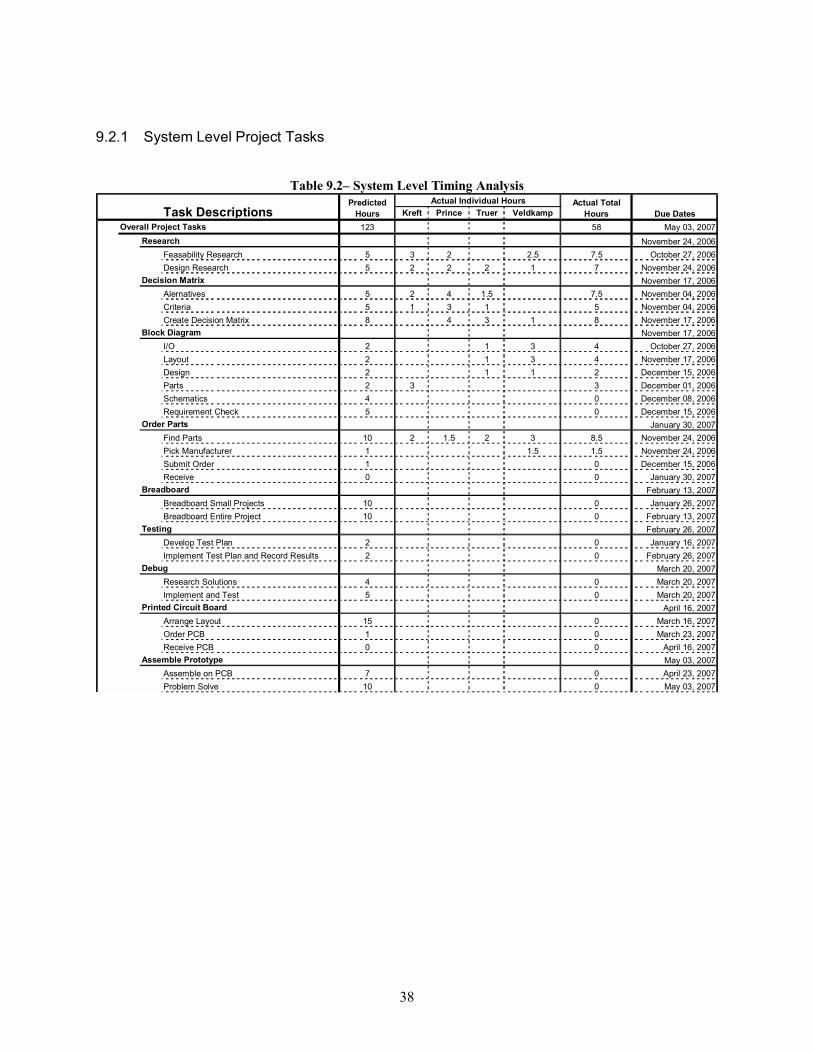
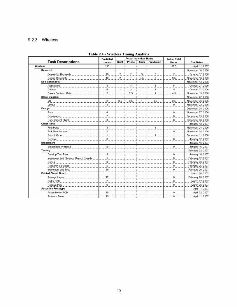
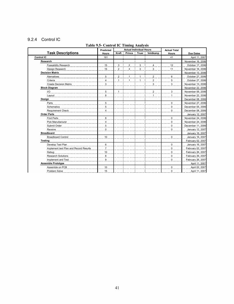
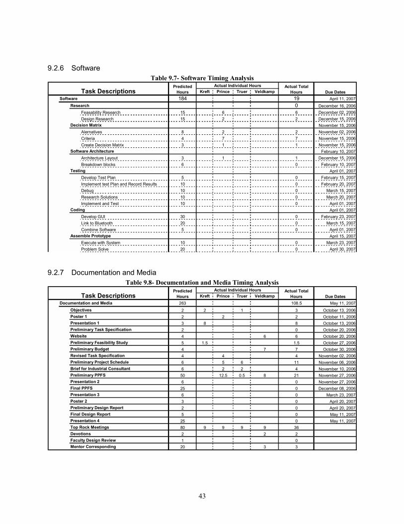
9.2.1 System Level Project Tasks .............................................................................................. 38 9.2.2 Remote Control ................................................................................................................ 39 9.2.3 Wireless ........................................................................................................................... 40 9.2.4 Control IC ........................................................................................................................ 41 9.2.5 Power Supply ................................................................................................................... 42 9.2.6 Software........................................................................................................................... 43 9.2.7 Documentation and Media ................................................................................................ 43
10 Acknowledgements ....................................................................................................................... 44 11 Conclusion.................................................................................................................................... 44 12 References .................................................................................................................................... 45 13 Appendix I � System Alternatives ....................................................................................................I
13.1 System Alternatives .................................................................................................................I 14 Appendix II � Project Schedule ..................................................................................................... IV
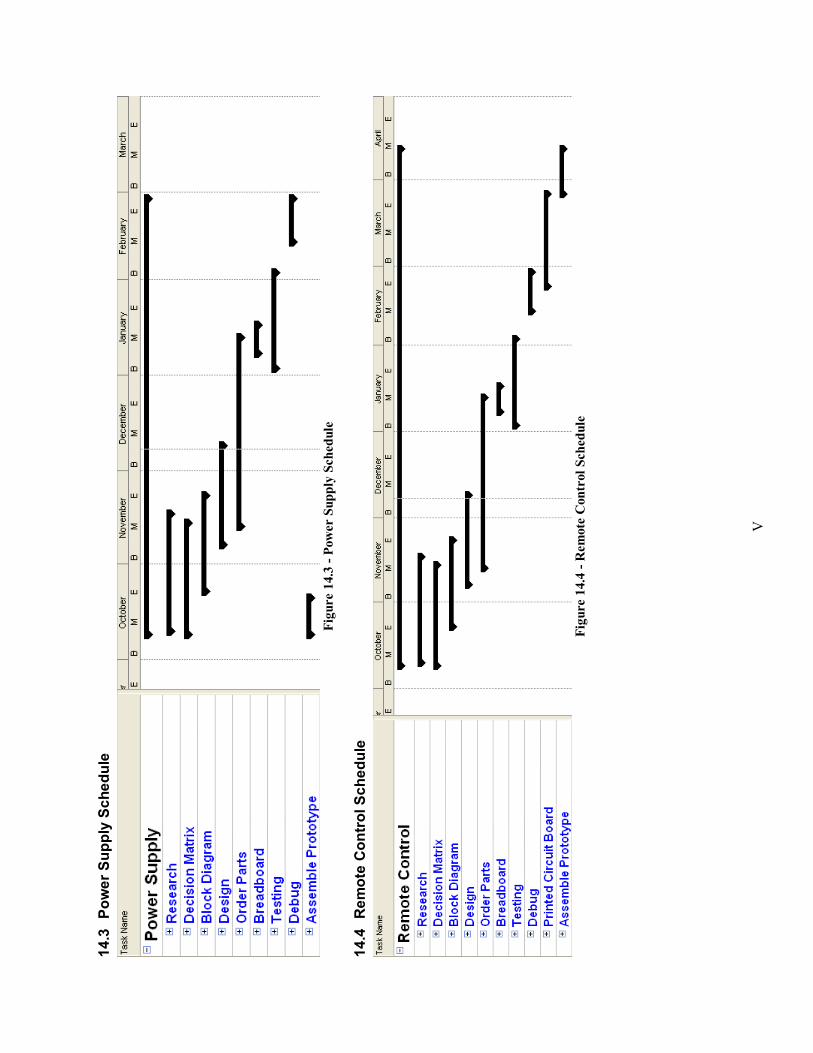
14.1 Overall Project Design Schedule ........................................................................................... IV 14.2 Control IC Schedule ............................................................................................................. IV 14.3 Power Supply Schedule ......................................................................................................... V 14.4 Remote Control Schedule ...................................................................................................... V 14.5 Software Schedule ................................................................................................................VI
iv
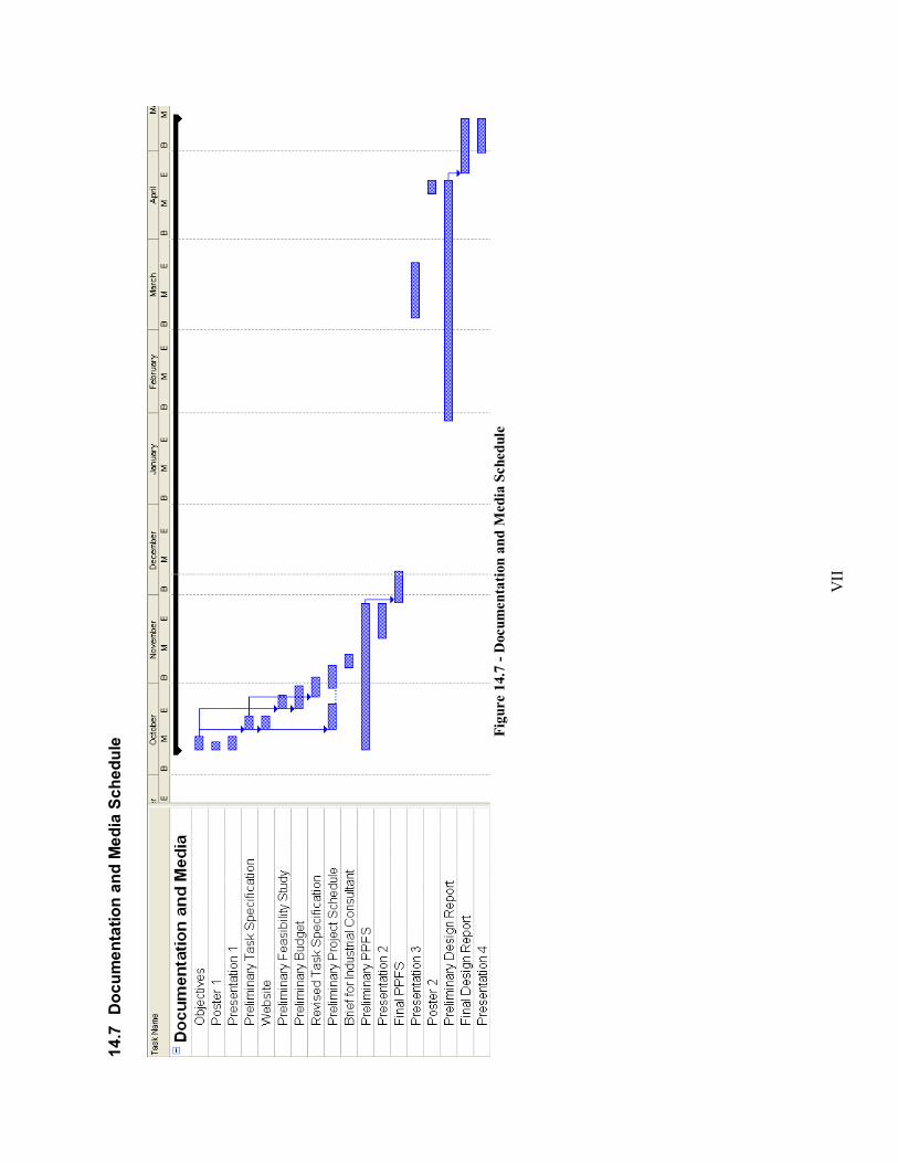
14.6 Wireless Schedule.................................................................................................................VI 14.7 Documentation and Media Schedule ....................................................................................VII
v
Table of Figures Figure 2.1 - Team LEDmote.................................................................................................................... 3 Figure 5.1 - Transistor Modeling ........................................................................................................... 10 Figure 5.2 - Remote Control External Design ........................................................................................ 15 Figure 5.3 - GUI Layout ........................................................................................................................ 19 Figure 5.4 - Software Architecture......................................................................................................... 21 Figure 7.1 - DVD Remote Control ......................................................................................................... 25 Figure 7.2 - IR Remote Control Block Diagram..................................................................................... 26 Figure 7.3 - Remote Control Button Array............................................................................................. 26 Figure 7.4 - Remote Control Button Array Circuit ................................................................................. 26 Figure 7.5 - Remote Control Button Encoding ....................................................................................... 26 Figure 7.6 - Remote Control Transmitter Chip ....................................................................................... 27 Figure 7.7 - IR Control Transmitter Chip Block Diagram....................................................................... 27 Figure 7.8 - Zigbee Remote Control Design........................................................................................... 28 Figure 8.1 - Corporate Operating System Market Share ......................................................................... 29 Figure 9.1 - Total Hours ........................................................................................................................ 37 Figure 13.1 - Distributed Lamp Power and Control ...................................................................................I Figure 13.2 - Centralized Lamp Power and Control ..................................................................................I Figure 13.3 - Distributed Lamp Power .................................................................................................... II Figure 13.4 � Comprehensive Block Diagram of Prototype.................................................................... III Figure 14.1 - Overall Timeline............................................................................................................... IV Figure 14.2 - Control IC Schedule ......................................................................................................... IV Figure 14.3 - Power Supply Schedule ..................................................................................................... V Figure 14.4 - Remote Control Schedule .................................................................................................. V Figure 14.5 - Software Schedule ............................................................................................................VI Figure 14.6 - Wireless Schedule ............................................................................................................VI Figure 14.7 - Documentation and Media Schedule ................................................................................VII
ADC Analog-to-Digital Converter API Application Programming Interface ASCII American Standard Code for Information Interchange COGS Cost of Goods Sold DCP Digitally Controlled Potentiometer DVD Digital Video Disk eMAC Enhanced Multiply Accumulate Unit ENGR Engineering FCC Federal Communications Commission FPGA Field Programmable Gate Array GUI Graphical User Interface I/O Input/Output IC Integrated Circuit IDE Integrated Development Environment IEEE Institute of Electrical and Electronics Engineers IPC Institute of Interconnecting and Packaging Electronic Circuits IR Infrared LCD Liquid Crystal Display LED Light Emitting Diode MSDN Microsoft Development Network OS Operating System OSC Ohio Supper Computing Center PCB Printed Circuit Board PIO Parallel I/O PLD Programmable Logic Device PPFS Project Proposal Feasibility Study PWM Pulse Width Modulation R&D Research and Development RGB Red Green Blue TBD To Be Determined TV Television UART Universal Asynchronous Receiver/Transmitter UL Underwriters Laboratories Inc. VAC Volts Alternating Current VDC Volts Direct Current
2 Project Overview Project LEDmote aims to design and prototype a wirelessly controlled lighting system using
multicolor LED lights. This lighting system will be flexible, so that it may be marketed in a variety of applications including conference room, home and theater lighting. The project feasibility study aims to show that such a product could successfully make a profit in today�s markets. The wireless control will be available through a remote control device and also via computer software which can be loaded either onto a wireless-compatible laptop brought into a room or onto a wirelessly-compatible local desktop computer. The lighting system will provide a range of color options to the user and will provide a variety of settings for light intensity. The lighting system is implemented by using a number of light fixtures, distributed throughout a room.
2
2.1 Innotec Project LEDmote is supported by Innotec Corporation located in Zeeland, MI. Innotec is
supplying funding for the prototype and assisting in providing requirements and project objectives. They will build the lamp modules for market based on the prototype lamp module design. Innotec is a growing company that designs and builds automated systems for the automobile industry. Innotec and its six satellite companies currently employ about 450 people. It chiefly operates in the West Michigan area, but has recently expanded globally, opening manufacturing plants in Hungary, China and Mexico. They are branching out into other industries especially in the LED industry. Our project will provide them with a design analysis report, a prototype, and a business analysis which they can use to potentially develop into a final product.
2.2 Mentor Tom Veenstra, an employee of Innotec, is the mentor for this project. Mr. Veenstra is a graduate
of the Calvin College Engineering program with a concentration in electrical engineering and currently leads R&D in the Innotec lighting division. He provides requirements and guidance for the design team. He is also the team�s customer, so the goal of this project is to provide Mr. Veenstra with a project that satisfies his requirements.
2.3 The LEDmote Group Team LEDmote is comprised of Chris Kreft, Dan Prince, Ryan Truer and Dustin Veldkamp. The
team is organized on an egalitarian basis with no designated leader but with individual accountability for specific responsibilities delegated by the group. Priorities are set on a �top rocks� system. In which the team members meet weekly to discuss the importance of task in a given week, and each team member chooses to take on a particular task as their focus area. In addition, team members will focus on accomplishing secondary targets to once the primary objectives are completed. Each team member of LEDmote took ownership of certain aspects of work at the beginning of the project. This ownership does not imply that they are responsible for all the work in these sections; it means they are responsible for driving those areas to completion. Each member must ensure their sections are completed and must assign tasks in their sections that must be completed. During the weekly �top rock� group sessions the team goes over everyone�s assigned work, then status reports are given on every. It is decided as a group which areas are top priority and the member in charge of that area is responsible for ensuring completion of that work. This team organization allows for individual responsibility so no one individual is left with more work than is fair. This type or team organization could cause neglect of some tasks, so once a week the team convenes to check that all important work is fairly assigned. Therefore at every team meeting we have to go over all tasks and make sure everything has been assigned an owner.
Chris Kreft was born in Philadelphia, Pennsylvania to Zimbabwean parents who returned home when he was two years old. He attended Gateway Primary and High Schools located in Harare, Zimbabwe before immigrating with his parents to the United Kingdom. In 2002, he chose to continue his education at Calvin College after discovering his interest in learning about the country of his birth and hearing a call from God. Besides his engineering interests, Chris enjoys learning about other cultures and their histories, playing and watching soccer and playing the guitar. He hopes to use his skills to one day work in International Development back on his home continent. Chris currently works for Apex Controls in Hudsonville, Michigan. For the project, Chris will be designing the power supply and LED prototype circuitry. He is also in charge of ensuring the project stays within budget constraints.
Dan Prince was born in Shelby, Michigan and was raised in New Era, Michigan. He went to New Era Christian School for his education from Preschool to the eighth grade. His high school education took place at Western Michigan Christian High School in Muskegon. Following his senior year of high school, he moved to Grand Rapids and began his freshman year at Calvin College, starting in the engineering
3
program. At the conclusion of his second year at Calvin, he chose an electrical and computer engineering concentration because of a growing affinity towards computers and electronics. He is now in his fourth year at Calvin and planning on graduating in May of 2007 with a bachelor�s degree of science in engineering. He currently works for Smiths Aerospace. Dan will work on the Bluetooth and control aspects of the project. He is also in charge of status reports, assists Dustin with market research, and builds test plans for the project.
Ryan Truer was born and raised in Grand Rapids, Michigan. He attended Sylvan Christian School from pre-school to eighth grade and after that obtained a high school education at Grand Rapids Christian High School. After high school he chose to attend Calvin College for a pre-architecture degree. After a year he switched into the electrical and computer engineering program. Ryan is currently in his fifth year at Calvin and plans to graduate in May 2007. He currently serves as an intern at Beta Integrated Concepts and also grades and lab assists for a microelectronics class. For the project, he is in charge of the remote control and Zigbee portion of the project. He also deals a lot with the creation and maintenance of the schedule for the team.
Dustin Veldkamp was born and raised in southwest Minnesota. He brings business background, education and experience to the group. He graduates in May 2007 from Calvin College with a degree in Business and Engineering. Dustin is currently employed with Innotec and is the team�s liaison with the company. For the project, Dustin will be managing the Control design, leading the software programming, maintaining the group schedule, and performing market research and financial analysis.
Figure 2.1 - Team LEDmote
3 Project Objective The objective [IT1]of Team LEDmote is to design and prototype a wirelessly controlled lighting
system using multicolor LED lights. The prototype will be used by our sponsor, Innotec, to develop a marketable lighting product. Wireless control will be implemented using two methods: a remote control device and software that can be loaded onto a laptop or in-room desktop computer. The computer will have a greater degree of functionality than the remote. The controllers will designate the light intensity delivered by the lighting modules as well as designating user-specified colors that the modules will emit. The lighting system is to be used for both aesthetic and practical purposes, thus it will match the lighting
4
capabilities of current systems as well as provide different colored accents. The lighting system will be affordable and fill a niche in the current market. The team intends to have a functioning prototype by May 2007.
4 Design Requirements
4.1 Design Norms The team is strongly interested in how the design of our system correlates with Christian values.
One way to do this is to identify the design norms that could apply to our project. Design norms are general principles that give an ethical guideline for this project and ensure that technology is truly in service of God and society.
The project design norms are transparency, harmony and stewardship. Transparency appears in the project in both hardware and software. In the hardware, the remote control is user-friendly, allowing a user to easily identify how to change colors, brightness and how to turn the lighting system on and off. In software, the user is able to easily identify functionality and the software should follow conventional programming standards.
Harmony is qualified in the following sentence by Gayle Ermer, an associate professor at Calvin College: �The design should be pleasing to use, attractive, and promote healthy relationships�. This norm, also known as integrity, is seen in the aesthetic value of the design which is fun, flexible, intriguing and easy to use.
Finally, stewardship [IT2]is seen in the use of LED lights as opposed to incandescent bulbs. The use of LED lights minimizes power consumption and thus has detrimental effects [IT3]on environment that occur from excessive energy consumption. Such detrimental effects include global warming from the burning of fossil fuels or damage to the environment from other power generation units such as hydroelectric dams interfering with natural water forms. In addition, LEDs do not have the toxic materials of lead and mercury that incandescent and fluorescent bulbs use, nor does a user need to be concerned with the possible dangers associated with broken glass from damaged bulbs of this type. The use of wireless technology minimizes the need for wiring between light modules, and so reduces the overall system cost[IT4]. Although the initial installation costs are greater, ultimately the long-term costs are minimized.
4.2 Overall System Requirements[IT5]
Using the design norms, the team determined a set of project requirements that will determine the success or failure of the project. In addition, the team listed features that would be desirable to appear in the design and prototype but which were determined unnecessary for the basic success of the project. The first requirement is that a wireless [IT6]controller (i.e. a remote control or a computer that has wireless technology and installed software) shall regulate the color and intensity of all [IT7]lamps simultaneously[IT8]. Wall-mounted switches at one of multiple entrances must be available to provide basic lighting function if a computer or remote is unavailable. The prototype must show some model of this function. The lighting system shall have a maximum transition time of two seconds. This is defined as the time between the user inputting an instruction, be it �turn the lighting system on� or �change all lamps to blue� to the change being completely effected.
At least two prototype lamps shall be built that shall communicate with each other. Their functionality shall be controlled and demonstrated by both types of wireless controller. The controller shall be able to select a minimum of five brightness settings and a minimum of sixteen different colors.
5
Innotec has specified that the PCB layout for the remote control must be in compliance with IPC610C.1 All requirements must be met by the time of design review in May of 2007.
In addition to the requirements, the team created additional features that would be desirable to see in the final prototype, but which were not necessary for success to be achieved. One desirable feature is a prototype that with a large range for communication between the lamp modules and the wireless controller. This is desirable so the room size can be maximized. Wireless protocol will play a major factor in determining this range. The team would also like to detect occupant presence in a room and create a schedule that turns the lamp modules on and off based on the time of day. Finally, the team would like to minimize the use of different wireless protocols as much as possible.
4.3 LED Requirements The focus of the project was to design a control system for lighting a room. The design did not
call for the making of the actual lamps to be mass-produced. The team deemed it necessary to build two prototype lamps to determine the power requirements and to demonstrate the functionality of the control system. Table 4.1 shows the requirements for the prototype lamps on which our design was based. These requirements were supplied by Innotec based on their estimates of what mass-produced lamps would look like.
Table 4.1 - LED Requirements
LED Description Requirements Number of total LEDs per lamp[IT9] 10 White LEDs per lamp 4 RGB LEDs per lamp 6 Max intensity (white LEDs) 800 lumens Max intensity (RGB LEDs) ??? lumens Max current per white LED 400mA Max current per RGB LED 50mA Lamp total power consumption ~25W Estimated number of colors 256 Dimming variability Continuous
4.4 Power Requirements Table 4.2 - Power Requirements
Power Requirements Input Max Min Continuous operating Voltage 250 VAC 90 VAC Surge voltage TBD - Temperature -10 degC 65 degC Frequency 40 Hz 70 Hz Conducted and Radiated Emissions and Immunity
Comply with FCC and UL requirements
-
Static Sensitivity 2kV[IT10] - Output Requirements Common voltage 5 VDC +/-5% Common current 5A max (short circuit protection)
White voltage 25V max White current per LED (4-6 LEDs total)
400mA max
RGB voltage 25V max RGB current 500mA max continuous
4.5 Laptop Requirements Operating System Windows XP
Protocol Bluetooth
Minimum operating distance 30ft
4.6 Remote Requirements Operating distance 30ft
Protocol Zigbee
Functions On/Off, color, intensity
4.7 Changing Requirements Changes to requirements occurred several times over the course of the project, prompted either by Innotec�s alterations or else from results of the team�s research. Innotec initially specified that the control system should regulate a desk lamp only. However, the team preferred that the system be able to accommodate many various lighting systems, including entire rooms.
5 Alternative Design Solutions
5.1 Overall System Alternatives At the beginning of the project several different alternatives were identified for the design and
setup of the system. The alternatives were developed in order for us to determine the best way of designing the system as a whole. In each alternative, the number of lamp modules is limited by wireless protocol choice, which will be discussed later. All wireless protocols will support at least seven active lamp modules simultaneously. Note that in all of the following decision matrices the following criteria definitions are used:
Table 5.1 - Decision Matrix Terms Decision Matrix Term Description
Price A blanket term for any costs incurred including part costs, manufacturing costs, power requirements
Flexibility Identifies ease of future adjustments and number of possible original installation combinations
User Friendly/Ease of use Weighs the ability of the user to quickly understand and use the system in a satisfying way
Reliability Weighs the longevity of the product
Availability Weighs the ease with which the product can be bought or built
7
5.1.1 Wall Switches
Wall-mounted on/off switches located at entrances allow basic control of lighting. The idea behind wall-mounted switches is simply to provide light to the room in the absence of other controllers such as the remote control or computer.
5.1.1.1 Criteria
The team determines that price, reliability, flexibility, availability and ease of use were important for the wall switches. Of these, reliability and user friendliness were deemed most important, followed closely by flexibility and low cost. Availability was the least important criterion.
5.1.1.2 Alternatives
Two alternatives were available. The first was a simple on/off switch that set the lighting modules to a preset brightness (adjustable for whatever types of room the lamp modules are used in), set to emit only white light. The second alternative was to include the features of the wireless controllers in the wall-mounted switches.
5.1.1.3 Decisions
Wall-mounted switches will control the power feed to all lamp modules. This provides a basic functionality in the event of failure or absence of wireless devices such as the remote control, laptop or in-room computer. The manual switching functionality was deemed essential for emergency cases. However, other functions of the lamp modules such as variable brightness and color will not be built-in to the wall switches. Adding these features to a wall-mounted switch decreases the need for a wireless controller such as a remote or laptop and thus the associated flexibility is reduced. The software and remote will provide on-off function for the lamp modules without the use of wall-mounted switches.
Table 5.2 - Wall Switch Decision Matrix
low
cos
t
flexi
bilit
y of
ove
rall
desi
gn
user
frie
ndlin
ess
avai
labi
lity
relia
bilit
y
Tota
ls
Weights (out of 10) 9 9 10 7 10 Switch Alternatives Simple on/off switch 9 9 8 8 10 398 Switch with all features 6 4 7 6 9 292
5.1.2 Centralized or Distributed Control
A key component in the system design is choosing either a centralized or a distributed control for each lamp module.
8
5.1.2.1 Criteria
The criteria for the choosing the control implementation includes price, flexibility (defined in this case as ease of installation), reliability and size.
5.1.2.2 Alternatives In a distributed system the computer and remote controller will have the ability to communicate
with each lamp module individually and independently. A centralized control will relay the control signals through a bus wiring system connected to each lamp module.
5.1.2.3 Decisions
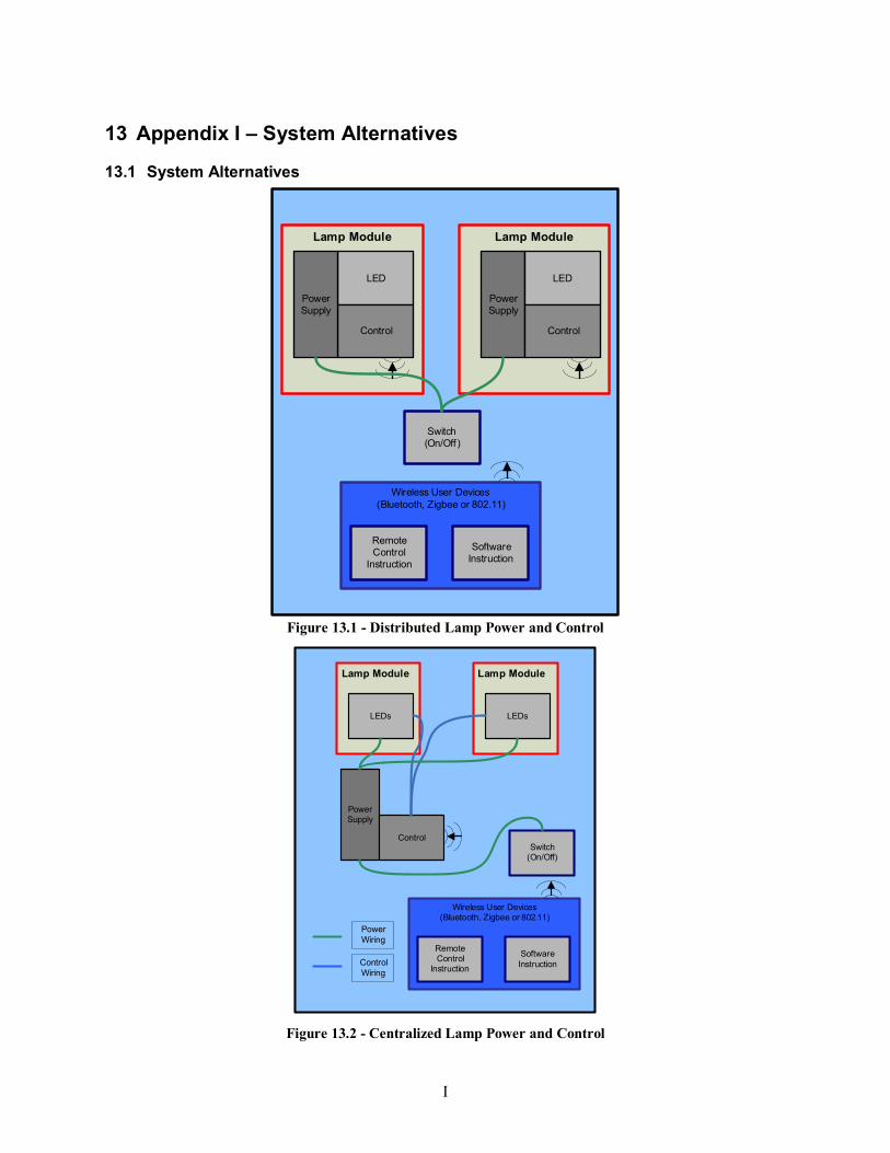
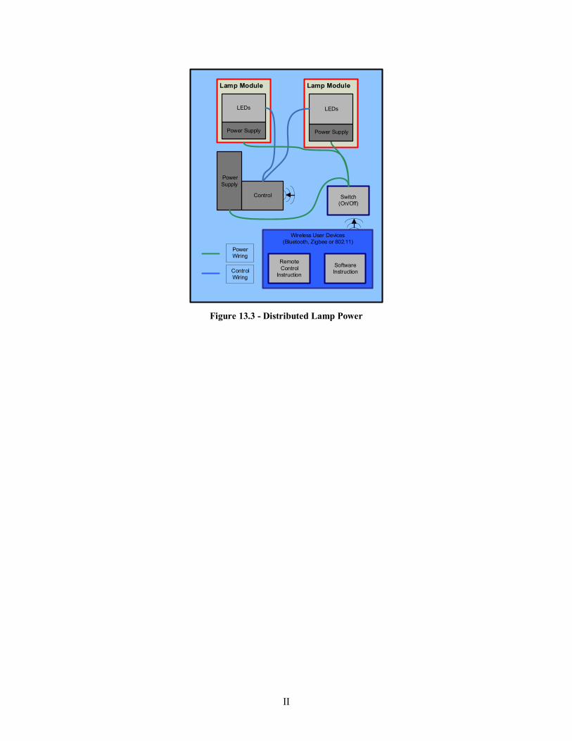
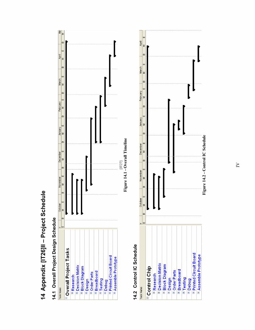
The decision matrix analysis shows that the pros and cons of each system are nearly balanced. The distributed control alternative provides the greatest amount of flexibility but the cost of installing a control in every fixture is very potentially expensive. The centralized control option has the advantage of minimizing the necessary number of system processors and therefore reducing cost. However, centralized control reduces the flexibility of the project by forcing physical wiring to be installed between the control circuitry and the lamp modules. This seems somewhat counter-intuitive to the team�s objective of creating a wireless lighting system. Hence, despite distributed control only marginally beating out centralized control, the team has chosen a distributed control system for their design. See Figures 13.1 and 13.3 of Appendix I for a diagram of distributed control. Figure 13.2 for centralized control.
Another decision to be made in considering system design is the choice of centralized or distributed power for each of the lamp modules.
5.1.3.1 Criteria
Since power supplies are expensive, the team considers price to be an important factor in choosing whether to use centralized or distributed power. The team has used other factors similar to those considered in the choice of centralized or distributed control. These include flexibility (defined again in this case as ease of installation), reliability and size.
5.1.3.2 Alternatives A centralized power system would power both the control circuitry and the lamp modules.
9
A distributed power system would require each lamp module to be wired to the building wiring of the room in which it is used.
5.1.3.3 Decisions
Similarly to the decision matrix for the control system, the power system decision matrix showed very little between the two options. A centralized system is probably more cost-effective than a distributed system because it minimizes the number of power supplies. The team chose to use distributed power supplies on each of the lamp modules, since a centralized power supply would require the technicians who installed the lighting system to do additional wiring beyond that which the room already contains.
By using a system that has both distributed power and distributed control, the overall lighting system has maximum flexibility. Lamp modules could be designed not just as individual lighting units in rooms but could be used almost anywhere in a room (for example, as a desk lamp).
Through discussions with Mr. Veenstra, the design was fleshed out further. The controller and power supply were connected through an amplifier and analog-to-digital converter (ADC). The circuitry in the amplifier would then allow power distribution to three different busses � common, RGB and white, so that the voltages supplied to the red, green and blue LEDs could easily be varied separately from the voltages supplied to the white LEDs. A comprehensive block diagram of this design is shown in Figure 13.4. In order to form a more concrete idea of the LED control, the following examination of amplification options were considered.
5.2 Amplifier Decisions Three alternatives were created to implement the amplifier stage: use of transistors, use of op-
amps, and pulse modulation to vary the frequency of the input signal. All three could be used to supply a range of power to the LEDs.
5.2.1 Criteria
Five design criteria were developed for the amplifier alternatives. Low cost was important in the design since the team did not want a significant part of the budget devoted to the amplification stage, which would detract from more expensive areas of the project. The second criterion was flexibility.
10
Flexibility for the amplifier was defined as the ease with which different distinct levels of gain could be obtained. The size and complexity criterion evaluated how extensive and complex the circuitry would need to be to have correct functionality. Availability was a measure of how difficult it would be for the team to locate, purchase and install the necessary components. The final and most important factor in amplification was the reliability of the system.
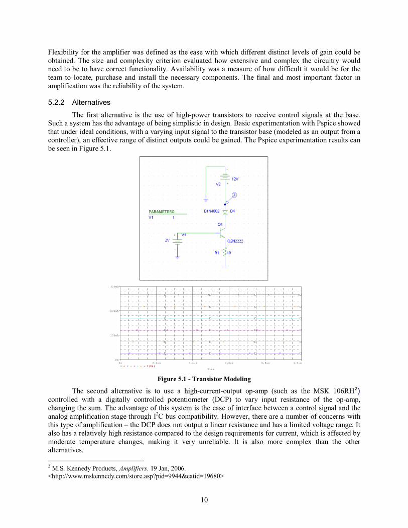
5.2.2 Alternatives
The first alternative is the use of high-power transistors to receive control signals at the base. Such a system has the advantage of being simplistic in design. Basic experimentation with Pspice showed that under ideal conditions, with a varying input signal to the transistor base (modeled as an output from a controller), an effective range of distinct outputs could be gained. The Pspice experimentation results can be seen in Figure 5.1.
Time
0s 0.2us 0.4us 0.6us 0.8us 1.0usI(D4)
0A
100mA
200mA
300mA
I(D4) Figure 5.1 - Transistor Modeling
The second alternative is to use a high-current-output op-amp (such as the MSK 106RH2) controlled with a digitally controlled potentiometer (DCP) to vary input resistance of the op-amp, changing the sum. The advantage of this system is the ease of interface between a control signal and the analog amplification stage through I2C bus compatibility. However, there are a number of concerns with this type of amplification � the DCP does not output a linear resistance and has a limited voltage range. It also has a relatively high resistance compared to the design requirements for current, which is affected by moderate temperature changes, making it very unreliable. It is also more complex than the other alternatives. 2 M.S. Kennedy Products, Amplifiers. 19 Jan, 2006. <http://www.mskennedy.com/store.asp?pid=9944&catid=19680>
11
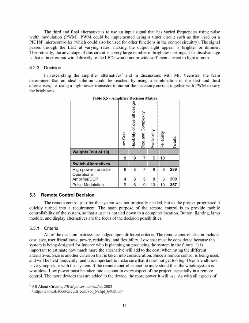
The third and final alternative is to use an input signal that has varied frequencies using pulse width modulation (PWM). PWM could be implemented using a timer circuit such as that used on a PIC18F microcontroller (which could also be used for other functions in the control circuitry). The signal passes through the LED at varying rates, making the output light appear is brighter or dimmer. Theoretically, the advantage of this circuit is a very large number of brightness settings. The disadvantage is that a timer output wired directly to the LEDs would not provide sufficient current to light a room.
5.2.3 Decision
In researching the amplifier alternatives3 and in discussions with Mr. Veenstra, the team determined that an ideal solution could be reached by using a combination of the first and third alternatives, i.e. using a high power transistor to output the necessary current together with PWM to vary the brightness.
5.3 Remote Control Decision The remote control [IT11]for the system was not originally needed, but as the project progressed it
quickly turned into a requirement. The main purpose of the remote control is to provide mobile controllability of the system, so that a user is not tied down to a computer location. Button, lighting, lamp module, and display alternatives are the focus of the decision possibilities.
5.3.1 Criteria All of the decision matrices are judged upon different criteria. The remote control criteria include
cost, size, user friendliness, power, reliability, and flexibility. Low cost must be considered because this system is being designed for Innotec who is planning on producing the system in the future. It is important to estimate how much more the alternative will add to the cost, when rating the different alternatives. Size is another criterion that is taken into consideration. Since a remote control is being used, and will be held frequently, and it is important to make sure that it does not get too big. User friendliness is very important with this system. If the remote control cannot be understood then the whole system is worthless. Low power must be taken into account in every aspect of the project, especially in a remote control. The more devices that are added to the device, the more power it will use. As with all aspects of 3 All About Circuits, PWM power controller. 2003 <http://www.allaboutcircuits.com/vol_6/chpt_6/9.html>
12
the project, the design of the remote must follow the design norms of the project. The remote control system should also be reliable. Flexibility will make sure that the system does not limit itself in any way.
5.3.2 Button Decisions This decision matrix, shown in Table 5.6, deals with the physical buttons[IT12] of the remote control. For this project, three possible input devices were chosen: slides, individual buttons, and a scroll wheel. These three options are shown below in Table 5.6, and weighted according to the criteria discussed above. The button alternative ended up slightly higher than the other two options because of its reliability. A slider has a preset position, which is a disadvantage if, when the lighting system is initially turned on, the lights automatically turn on to whatever preset position the slider is in. A user may not want the lights to be fully bright or fully dark when the lighting system is first turned on. The advantage of the other button systems is that, when the lighting system is turned on, it sets to a default medium brightness that can be adjusted up or down. There are no physical limitations on the button or scroll wheel system over the slider system. The main advantage of a button system over a scroll wheel system is minimization of costs.
While the actual market-product LEDs will be provided by Innotec, the team felt it was necessary for the remote control decision matrix (and subsequent control decisions) to examine the alternatives for LED lighting given the project requirements. The decision matrix, shown in Table 5.7, weighs the different lighting techniques of the Red Green Blue (RGB) LEDs and white LEDs. More specifically, it raises the question of how many different colors the remote control will offer and what range of dimming capabilities it can provide. Both of these options deal with how the remote control will increase the color or brightness level. This issue is not a problem for the remote because it will have three different color buttons, each controlling one of the three colors in the RGB LED. It will then send out an up or down signal of the specific color pressed. The two different alternatives are weighted closely in the end because no significant additional design is needed to add more colors. The processor receives a signal through the wireless transmitting device to increase the color by a certain[IT13] increment [IT14]for each button press.
The decision matrix, shown in Table 5.8, discusses the different alternatives on how the remote controls multiple lamps. The team decided that the remote will regulate all the lamp modules at the same time. Allowing the remote control to individually manipulate different lamps in the area is too complicated to fit into a single remote while still providing an ease of use to the consumer. The alternative is to create a lighting schedule with the remote control. This alternative did not stand up to other alternatives, adding unnecessary complexity to the remote control, and so increasing its cost. [IT15]
Weights (out of 10) 10 7 3 7 8 5 Lamp Module Alternatives Individual Lamp Modules 4 2 5 4 6 8 185 All Lamp Modules at Once 9 7 7 8 7 3 287 Scheduler Control 2 5 5 3 5 7 166
5.3.5 Display Decision
The last decision, shown in Table 5.9, shows the display options of the remote control. As shown in the table, the LCD type display is highly unpractical for the remote control. If a display is included in the remote control it could possibly be more user-friendly. However, cost would be higher due to a need for an extra processor and LCD screen. These results correctly reflect the scope of the project. The function of the prototype remote is simply to control the lamp modules and colored buttons. Proper labeling of buttons easily meets this specification.
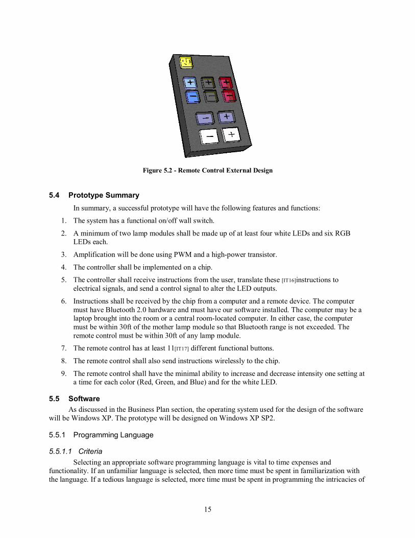
This project does not only cover the technical electrical design but also covers aspects of the physical design. A quick sketch of the remote, shown in Figure 5.2, reveals some of the functions of the remote control. These functions were determined earlier in the decision matrix but are discussed further in this section. First of all, the remote control will have a power button. This is represented in the diagram as the yellow button in the upper left corner of the remote. It will allow the system to be turned on and off when a person enters or leaves the room. The next set of buttons contains control for the color adjustment capabilities. These are shown in the middle row of the remote for each of the three colors with a plus and minus buttons function. The different colors from left to right are blue, green, and red. The third bank of buttons deals with the ability of the remote controls to dim and brighten the lights. The grey plus and minus simultaneously change the level of brightness of the color lights giving the effect of dimming. The white plus and minus buttons control the brightness of the white LEDs.
It is important to note that the functions are controlled by simple plus and minus buttons. This is the best option because it allows for the most efficient results from the remote. The use of slides or rotating buttons. This option would not work with the system because if the lights initially come on at a medium brightness and at the same time the sliders are all the up, the user is not able to increase the light to the full brightness. With the use of plus and minus, the remote is able to continuously increase or decrease each function.
15
Figure 5.2 - Remote Control External Design
5.4 Prototype Summary In summary, a successful prototype will have the following features and functions:
1. The system has a functional on/off wall switch.
2. A minimum of two lamp modules shall be made up of at least four white LEDs and six RGB LEDs each.
3. Amplification will be done using PWM and a high-power transistor.
4. The controller shall be implemented on a chip.
5. The controller shall receive instructions from the user, translate these [IT16]instructions to electrical signals, and send a control signal to alter the LED outputs.
6. Instructions shall be received by the chip from a computer and a remote device. The computer must have Bluetooth 2.0 hardware and must have our software installed. The computer may be a laptop brought into the room or a central room-located computer. In either case, the computer must be within 30ft of the mother lamp module so that Bluetooth range is not exceeded. The remote control must be within 30ft of any lamp module.
7. The remote control has at least 11[IT17] different functional buttons.
8. The remote control shall also send instructions wirelessly to the chip.
9. The remote control shall have the minimal ability to increase and decrease intensity one setting at a time for each color (Red, Green, and Blue) and for the white LED.
5.5 Software As discussed in the Business Plan section, the operating system used for the design of the software
will be Windows XP. The prototype will be designed on Windows XP SP2.
5.5.1 Programming Language
5.5.1.1 Criteria Selecting an appropriate software programming language is vital to time expenses and
functionality. If an unfamiliar language is selected, then more time must be spent in familiarization with the language. If a tedious language is selected, more time must be spent in programming the intricacies of
16
the language. Therefore, one heavily weighted criterion must be how familiar the team is with the language, measured as the amount of previous experience team members have had with each language. It must be considered whether or not the language is adequate to fulfill the desired functions of software for this project. The software must interface with a Bluetooth card. It must have the capability to create a graphical user interface (GUI) that is transparent to the user. It must also be capable of creating applications compatible with Windows; because that is the OS we intend to install our prototype software on. Without adequate software no matter how familiar the team is with the language, certain functions will not be able to be created. Another criterion is an adequate support system to answer all programming queries. In summary, the criteria are previous experience, functional Bluetooth interface, capacity to create transparent GUI, ability to create windows compatible applications, and an adequate support system.
5.5.1.2 Alternatives There are three alternatives considered for software programming language. The alternatives are
Java, C++, and Basic. Java is an object-oriented programming language developed by Sun Microsystems. It is designed to be executed on multiple operating systems. It is also designed for using computer networks.4 C++ is a high-level programming language originally developed by Bell Labs.5 Basic stands for �Beginner�s All-purpose Symbolic Instruction Code� and originated at Dartmouth College. It was created as a programming language for the non-technical user.6
5.5.1.3 Decision
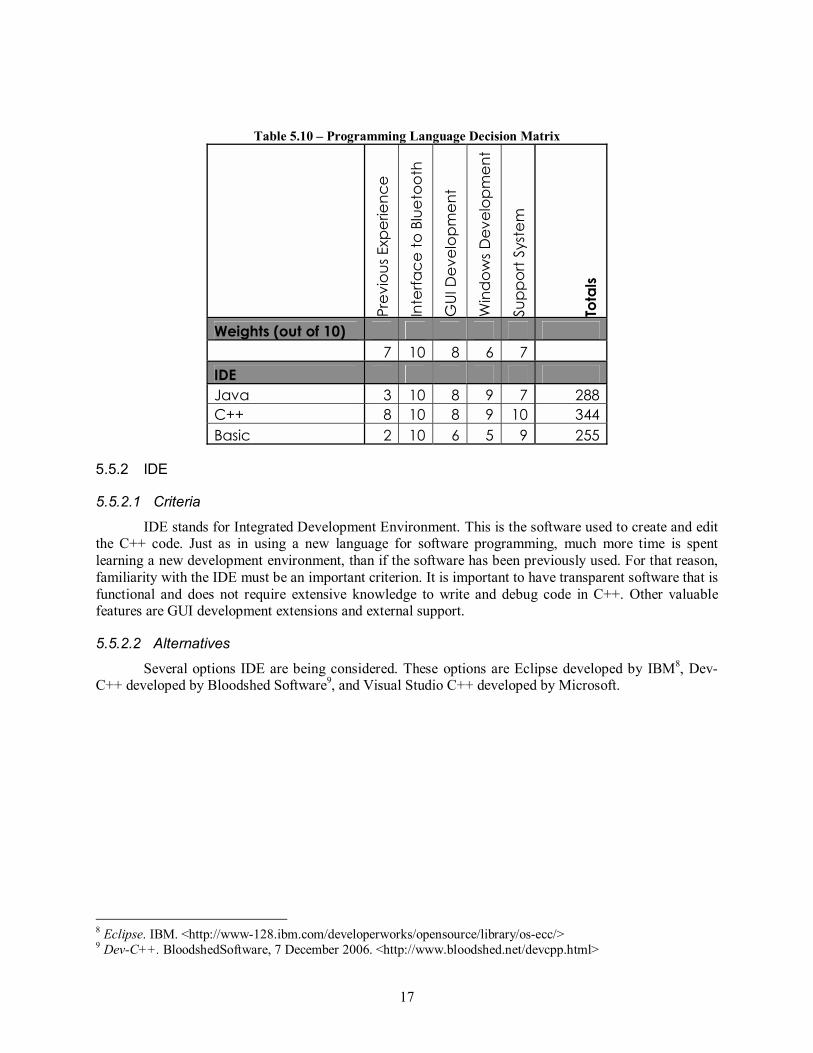
The decision matrix in Table 5.10 shows C++ as the superior programming language choice for software development. The major factor in making this decision was that the team has more collective experience in coding C++. This includes having two classes in programming C++ and various other C++ programming tasks. Other factors that support this decision are the extensive support structure available on MSDN (Microsoft Developer Network). MSDN has extensive resources in developing software with specific applications for windows, developing GUI, and interfacing to Bluetooth.7 Java has a wide variety of applications and has all the required capabilities, but the team�s unfamiliarity with the language and its unknown complexities ruled Java out as an acceptable alternative. Although the team has had no previous experience with Basic and it is a much simpler language to learn, it is more limited in its functionality, and was ruled out.
4 Java (Programming Language). Wikipedia, 7 December 2006. <http://en.wikipedia.org/wiki/Java_%28programming_language%29> 5 C++. Wikipedia, 7 December 2006. <http://en.wikipedia.org/wiki/C%2B%2B> 6 BASIC. Wikipedia, 7 December 2006. <http://en.wikipedia.org/wiki/BASIC> 7 MSDN. 7 December 2006. <http://msdn2.microsoft.com/en-us/default.aspx >
IDE stands for Integrated Development Environment. This is the software used to create and edit the C++ code. Just as in using a new language for software programming, much more time is spent learning a new development environment, than if the software has been previously used. For that reason, familiarity with the IDE must be an important criterion. It is important to have transparent software that is functional and does not require extensive knowledge to write and debug code in C++. Other valuable features are GUI development extensions and external support.
5.5.2.2 Alternatives
Several options IDE are being considered. These options are Eclipse developed by IBM8, Dev-C++ developed by Bloodshed Software9, and Visual Studio C++ developed by Microsoft.
The best alternative for an IDE will be Visual Studio C++. The main reasons for choosing this program are the program unfamiliarity to the team members and availability of support. It has easy and versatile features for developing GUI. MSDN is specifically geared towards aiding programmers with Visual Studio C++, so large volumes of information are readily available online. Eclipse has previously been used by the team members. The major shortcomings were its lack of GUI features of Visual Studio. It also does not have a support system that is as well developed as MSDN. Dev-C++ is an open source program, which is accompanied by many design forums, but it lacks structure in its support system. Dev-C++ is also unfamiliar to all of the team members, so added time for familiarization would extended the software programming schedule.
Table 5.11 - IDE Decision Matrix Pr
evio
us E
xper
ienc
e
Tran
spar
ent I
nter
face
GUI
Fea
ture
s
Ava
ilabl
e Su
ppor
t
Tota
ls
Weights (out of 10) 9 8 3 9 IDE Visual C++ 9 8 9 10 262 Eclipse 5 8 4 7 184 Dev-C++ 1 8 9 8 172
19
5.5.3 Software Design
5.5.3.1 GUI Layout
Figure 5.3 - GUI Layout
20
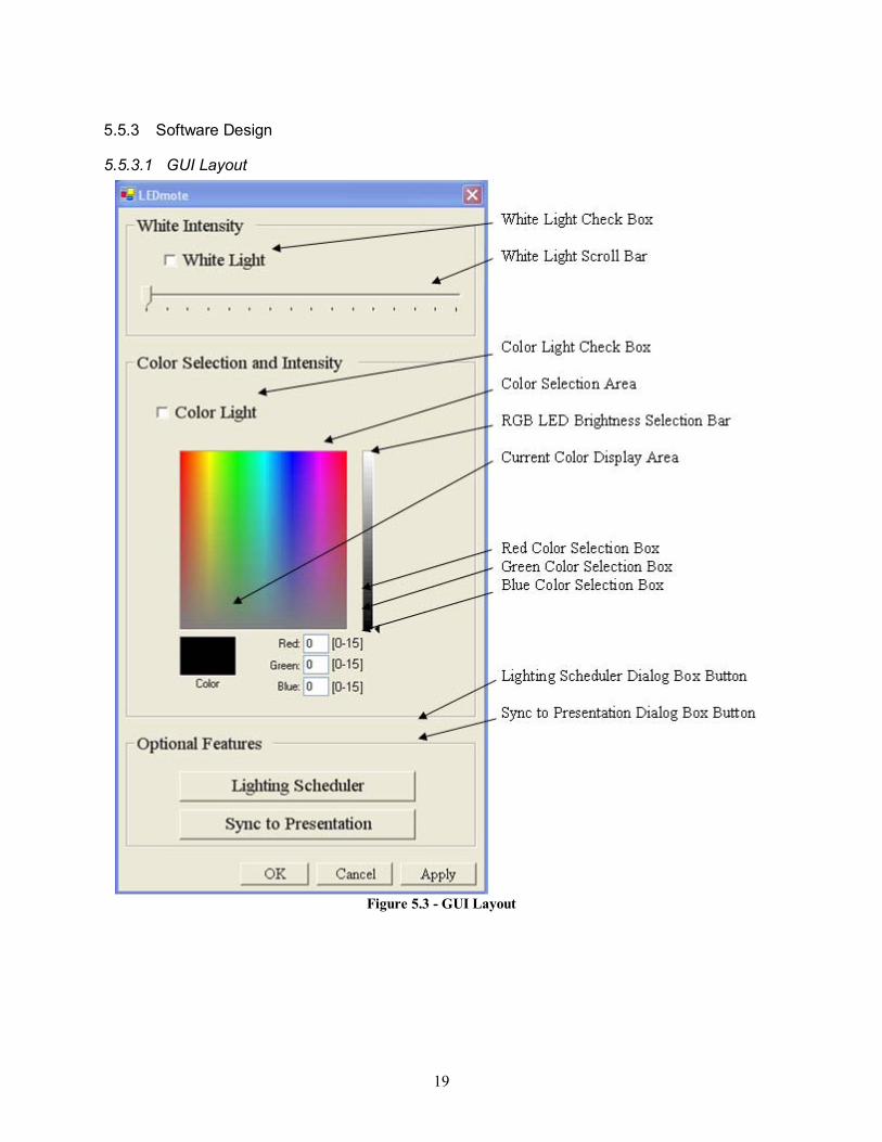
The concept of the GUI is illustrated in Figure 5.3. All features of the GUI are subject to change. The layout and functions of each feature in Figure 5.3 are shown in Table 5.12.
Table 5.12 - GUI Functions
White Intensity White Light Check Box
Status: Checked = White LEDs ON Unchecked = White LEDs OFF
White Light Scroll Bar
Each tick mark represents a brightness setting of the white LEDs. The left most being the dimmest and the right most being the brightest. There are 16 tick marks; each represents an increment of brightness.
Color Selection and Intensity
Color Light Check Box
Status: Checked = RGB LEDs ON Unchecked = RGB LEDs OFF
Color Selection Area
The user can click a certain color and the room will reflect that color when either the �OK� or �Apply� Button is pressed. This feature will be more limited than it appears in Figure 5.3, because the picture shown has 32-bit color capabilities and our design will only support 12-bit color.
RGB LED Brightness Selection Bar
This functions similarly to the White Light Scroll Bar, with the exceptions that the RGB bar is positioned vertically. There are still 16 settings of brightness.
Current Color Display
This box displays the currently selected color.
Red Color Selection Box
The user can type in a numerical value of brightness for the red LEDs from a range of 0 to 15.
Green Color Selection Box
The user can type in a numerical value of brightness for the green LEDs from a range of 0 to 15.
Blue Color Selection Box
The user can type in a numerical value of brightness for the blue LEDs from a range of 0 to 15.
Optional Features Lighting Scheduler Dialog Box Button
This button opens up a new dialog box that runs the program for a lighting schedule. This feature is still undetermined at this point.
Sync to Presentation Dialog Box Button
This button opens up a new dialog box that runs the sync to presentation program. This feature is still undetermined at this point.
Window Features X Button This button closes the window without applying the new settings. OK Button This button closes the Window and applies the new settings Cancel Button This button closes the window without applying the new settings. Apply Button This button applies the new settings without closing the window.
5.5.3.2 Software Architecture
The software architecture, shown in Figure 5.4, is the hierarchy leading from the user interface to the Bluetooth module.
21
GUI
Windows API
Bluetooth Driver
Bluetooth Hardware
Figure 5.4 - Software Architecture
The GUI receives input directly from the user and also displays output to the user. When receiving an input from the user, the GUI transfers it through a Windows API to the Bluetooth Driver, and directs the Bluetooth hardware to send the desired instruction. The instruction is decoded in the hardware by the controller and pulses are sent to LEDs. When a command is received by the controller from the remote, it relays onto other Zigbee devices and relays back through Bluetooth transmission to the laptop controller. When received by the Bluetooth hardware on the laptop, the signal percolates back up the hierarchy and is reflected in the GUI by a change in either the color selected or white LED intensity setting.
5.6 Wireless Protocol
5.6.1 Criteria
The wireless protocol decision factors in many different criteria. The protocol that is selected should be readily available in current laptops for more marketability. There should also be wireless modules available to include in a remote control. The modules that are implemented in the remote control should have low power consumption to maximize the life of the battery or power storage device in the remote control. Data transfer rates are the lowest concern, because all alternatives have speeds sufficient to send data. Our remote must be comfortable to hold, which means that the wireless module must be compact. Module size in the decision matrix was rated highly with small size.
Another concern that is not important for functionality, but still a consideration, is security. Although highly sensitive information is not being transmitted, a security breach will probably mean a major annoyance as the system behaves unpredictably. Interference is a concern, but many wireless protocols are specifically designed to mitigate noise. If there is a significant amount of interference, it will slow the response of the light. Anything short of that will not be noticeable. The range is a very important criterion. Range determines the size of the room that the LEDmote system can be implemented in. Therefore, it is in the higher end of the spectrum of criteria weightings. The final criterion is cost, which is a factor in all products produced for commercial sales. Minimizing cost is essential to the LEDmote business model.
5.6.2 Alternatives
There are eight alternatives being considered for a suitable wireless protocol. Three Bluetooth alternatives include class 1, 2, and 3, each of which has a maximum data transfer rate of 3Mbps. Class 1
22
has a range of 100m and maximum power of 100mW. Class 2 has a range of 10m and a max power of 2.5mW. Class 3 is another step down in range at 1m and a max power of 1mW.10
IEEE 802.11 also has three alternatives being considered. They are 802.11a, b, and g. 802.11b operates with a maximum data rate of 11Mbps and a range of approximately 100m. 802.11g also has a range of 100m but can transmit with a max data transfer rate of 54Mbps. 802.11a has a shorter range of 50m because it uses the 5GHz frequency band, where as 802.11a and g use the 2.4GHz band. 802.11a matches the 54Mbps transfer rate though.11
As an alternative to home computer wireless protocols, Zigbee and Infrared were considered. Zigbee is a protocol with a much slower data rate of 250kbps, however, it�s not beneficial in its repeating feature. It effectively takes the signal sent out by the master unit and relays it throughout the entire array of Zigbee modules programmed to receive the signal, as long as they are within range of each other. This gives it the largest effective range of all the wireless protocols being considered in this set of alternatives.12 Infrared is a much more simplistic form of data transfer and data is relocated almost instantly, but line-of-sight connection is required and the range is limited to 2.5m.13
5.6.3 Decision
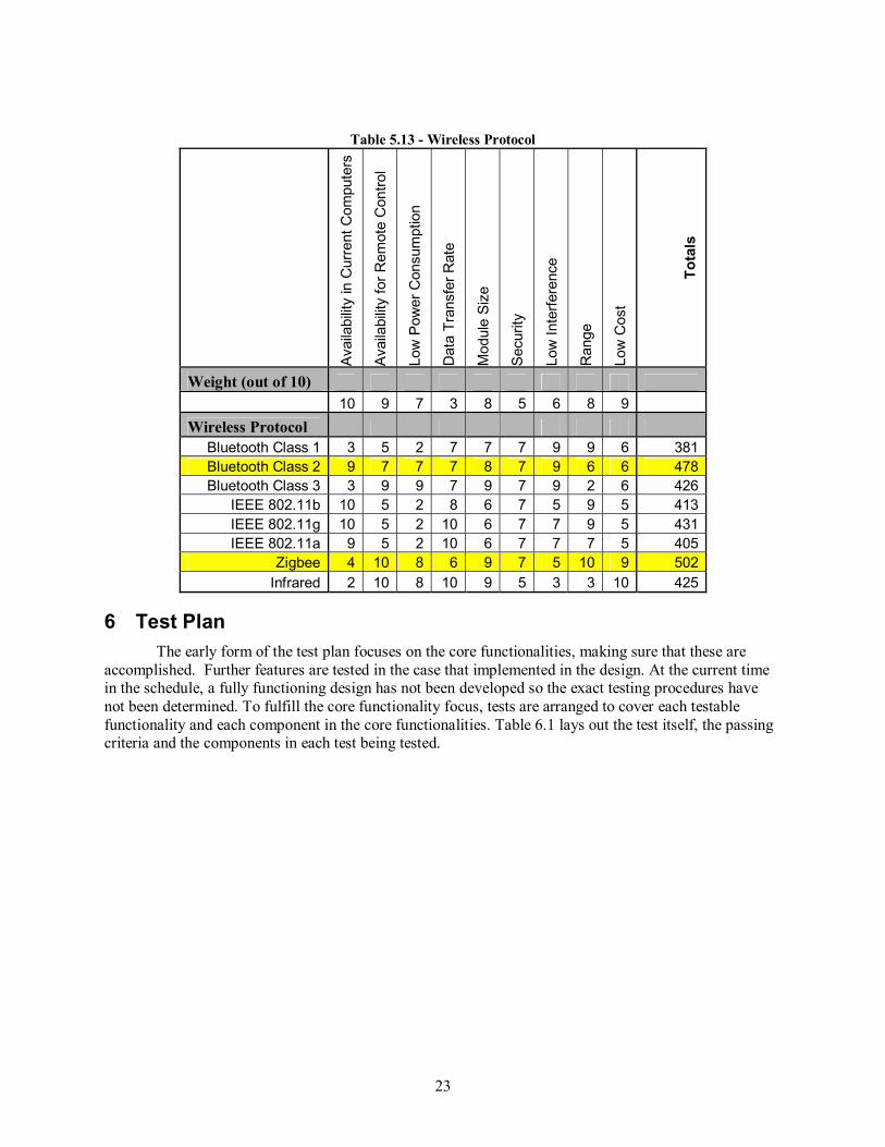
As shown in Table 5.13, Zigbee is the alternative deemed best for the LEDmote system. It is highlighted along with Bluetooth Class 2. Both rows are highlighted because both protocols will be combined to use the benefits of each. Bluetooth had much better scores in terms of availability in the current computers. Zigbee extends the range by relaying the signal to each additional lamp module in a room. In this system, a �mother lamp module� receives instructions and sends signals in both Zigbee and Bluetooth format, while all other lamp modules do not have Bluetooth compatibility. The remote control would thus be able to send instructions to any lamp module in the room that was within its range while the mother lamp module would need to be within range of the Bluetooth-compatible computer.
10 Bluetooth. Wikipedia, 8 December 2006. <http://en.wikipedia.org/wiki/Bluetooth> 11 IEEE 802.11. Wikipedia, 8 December 2006. <http://en.wikipedia.org/wiki/802.11> 12 Zigbee. Wikipedia, 8 December 2006. < http://en.wikipedia.org/wiki/Zigbee> 13 Infrared Data Association. Wikipedia, 8 December 2006. <http://en.wikipedia.org/wiki/Infrared_Data_Association>
23
Table 5.13 - Wireless Protocol
Ava
ilabi
lity
in C
urre
nt C
ompu
ters
Ava
ilabi
lity
for R
emot
e C
ontro
l
Low
Pow
er C
onsu
mpt
ion
Dat
a Tr
ansf
er R
ate
Mod
ule
Siz
e
Sec
urity
Low
Inte
rfere
nce
Ran
ge
Low
Cos
t
Tota
ls
Weight (out of 10) 10 9 7 3 8 5 6 8 9
Wireless Protocol Bluetooth Class 1 3 5 2 7 7 7 9 9 6 381 Bluetooth Class 2 9 7 7 7 8 7 9 6 6 478 Bluetooth Class 3 3 9 9 7 9 7 9 2 6 426
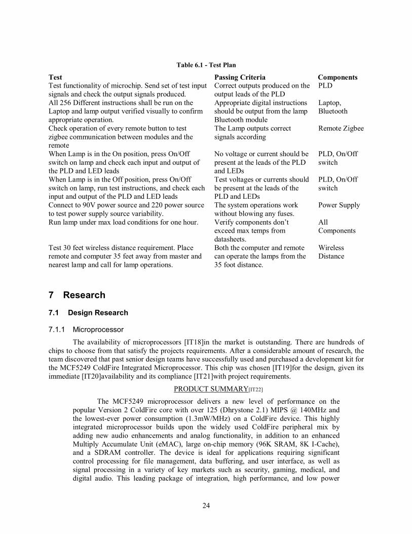
6 Test Plan The early form of the test plan focuses on the core functionalities, making sure that these are
accomplished. Further features are tested in the case that implemented in the design. At the current time in the schedule, a fully functioning design has not been developed so the exact testing procedures have not been determined. To fulfill the core functionality focus, tests are arranged to cover each testable functionality and each component in the core functionalities. Table 6.1 lays out the test itself, the passing criteria and the components in each test being tested.
24
Table 6.1 - Test Plan
Test Passing Criteria Components Test functionality of microchip. Send set of test input signals and check the output signals produced.
Correct outputs produced on the output leads of the PLD
PLD
All 256 Different instructions shall be run on the Laptop and lamp output verified visually to confirm appropriate operation.
Appropriate digital instructions should be output from the lamp Bluetooth module
Laptop, Bluetooth
Check operation of every remote button to test zigbee communication between modules and the remote
The Lamp outputs correct signals according
Remote Zigbee
When Lamp is in the On position, press On/Off switch on lamp and check each input and output of the PLD and LED leads
No voltage or current should be present at the leads of the PLD and LEDs
PLD, On/Off switch
When Lamp is in the Off position, press On/Off switch on lamp, run test instructions, and check each input and output of the PLD and LED leads
Test voltages or currents should be present at the leads of the PLD and LEDs
PLD, On/Off switch
Connect to 90V power source and 220 power source to test power supply source variability.
The system operations work without blowing any fuses.
Power Supply
Run lamp under max load conditions for one hour. Verify components don�t exceed max temps from datasheets.
All Components
Test 30 feet wireless distance requirement. Place remote and computer 35 feet away from master and nearest lamp and call for lamp operations.
Both the computer and remote can operate the lamps from the 35 foot distance.
Wireless Distance
7 Research
7.1 Design Research
7.1.1 Microprocessor
The availability of microprocessors [IT18]in the market is outstanding. There are hundreds of chips to choose from that satisfy the projects requirements. After a considerable amount of research, the team discovered that past senior design teams have successfully used and purchased a development kit for the MCF5249 ColdFire Integrated Microprocessor. This chip was chosen [IT19]for the design, given its immediate [IT20]availability and its compliance [IT21]with project requirements.
PRODUCT SUMMARY[IT22]
The MCF5249 microprocessor delivers a new level of performance on the popular Version 2 ColdFire core with over 125 (Dhrystone 2.1) MIPS @ 140MHz and the lowest-ever power consumption (1.3mW/MHz) on a ColdFire device. This highly integrated microprocessor builds upon the widely used ColdFire peripheral mix by adding new audio enhancements and analog functionality, in addition to an enhanced Multiply Accumulate Unit (eMAC), large on-chip memory (96K SRAM, 8K I-Cache), and a SDRAM controller. The device is ideal for applications requiring significant control processing for file management, data buffering, and user interface, as well as signal processing in a variety of key markets such as security, gaming, medical, and digital audio. This leading package of integration, high performance, and low power
25
consumption give quick access in the market to high quality software modules, easy code reuse, and extensive third party tool support.14
7.1.2 Bluetooth Module
Several Bluetooth manufacturing companies were contacted for chip information, pricing, and applicability. The response from these corporations directed us to A7 engineering, located in California. A7 engineering offers complimentary development kits [IT23]to university students and chips satisfy the requirements of our design. Calvin College senior design teams of the past have had success using the same chips. A request for the eb100-SER development kit has been sent and the team is awaiting approval.
PRODUCT SUMMARY
The A7 Engineering eb100-SER module is a highly integrated and easy to use Bluetooth solution designed for low cost and reliability. All components of the Bluetooth stack are implemented on board so that an additional host processor code is not required. Once a connection to another Bluetooth device has been established, the link has the appearance of a cabled serial connection, eliminating the need for special wireless protocol knowledge. Simple UART communications facilitate the interface between the host processor and the eb100-SER radio. This UART interface [IT24]may be used to discover, connect, and communicate with other Bluetooth devices through simple ASCII commands.15
7.1.3 Remote Control
The remote control is a very old type of technology that uses an IR transmitter and receiver. Much documentation is available on remote controls due to the prevalence of DVDs, TVs and home stereo systems. This section is dedicated to learning about these technologies by first hand analysis of a Cyber Home CH-DVD 300 DVD player remote control, shown in Figure 7.1.
Figure 7.1 - DVD Remote Control
7.1.3.1 Internal Design
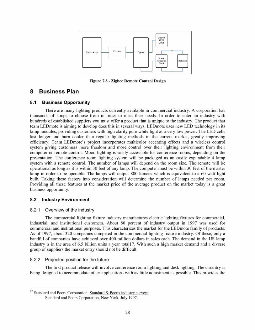
The internal workings of the remote control contain six parts, shown in Figure 7.2. These are Button Array, IR Control Transmitter Chip, OSC Circuit, Power Regulator Circuit, and an IR LED. Not all of the parts of the remote control can be used in our project, but they all helped to understand how the remote control for the LEDmote system is going to work.
14 Freescale Semiconductor, MCF5249 : Integrated ColdFire Version 2 Microprocessor. May 2006. <http://www.freescale.com/webapp/sps/site/prod_summary.jsp?code=MCF5249&nodeId=023Z1D2GFkVmp1> 15 A7 Engineering. EmbeddedBlue eb100-SER OEM Bluetooth Serial Module. September 2006. <http://www.a7eng.com/products/embeddedblue/serial/eb100-SER.htm>
26
Figure 7.2 - IR Remote Control Block Diagram
First, the button array is very useful because this remote control uses a simple way of implementing [IT25]its buttons and is easy to understand. The button array contains two parts, a physical button layer shown in Figure 7.3 and a circuit layer connected to the transmitter chip shown in Figure 7.4. The physical button layer is a manufactured part that contains a circular metal contact that will connect two leads on the circuit board button array. These two connected leads complete a path to the transmitter chip.
Figure 7.3 - Remote Control Button Array
Figure 7.4 - Remote Control Button Array Circuit
This button array allows 44 buttons to be connected through only 8 different input pins on the transmitter chip. A block diagram provided by the transmitter chip datasheet16 is shown in Figure 7.5. An example, if button 14 is pushed, it will connect Vcc to pins KI1 and KI/02, which is later analyzed in the chip.
Figure 7.5 - Remote Control Button Encoding
16 Datasheet4U, Infrared Remote Control Transmitter. 8 Dec 2006. <http://www.datasheet4u.com/html/S/C/6/SC6122-001_ETC.pdf.html>
27
Second, the IR Control transmitter chip provides some useful information for the remote control design. This chip is made of five blocks, shown in Figure 7.7. These are the key input scan circuit, an internal OSC circuit, timing generation, control circuit, code generation circuit, and the output control circuit. The only parts of this circuit that apply to the LEDmote project are the key input scan and the code generation circuit. These two parts analyze the button input and sends it to the output circuit. The code generation circuit is like an encoder, which takes the data from the input and sends it as binary code to the output control circuit. This information is useful because the button inputs might have to be encoded in a similar fashion before it reaches the wireless input of a lamp module.
Figure 7.6 - Remote Control Transmitter Chip
Figure 7.7 - IR Control Transmitter Chip Block Diagram
The external OSC circuit and the power regulator circuit of the remote control are not useful to the project and therefore not analyzed in detail. The batteries are relevant, as the remote will need some kind of power source, but the power consumption of the remote control and the specific components the remote will use have not yet been determined. Specific battery will be determined at a later time. The external OSC circuit will be contained within the Zigbee controller, and since the remote control is using Zigbee, an IR Led is not used.
Now that the analysis of the DVD player remote control is done, some of the information should be applied to the design of the one in the LEDmote project. As said before, the button layout and coding will be most useful in the design. At this point a Zigbee module has not been chosen. The decision of using Zigbee for the remote was decided recently and there has not been a sufficient amount of time to choose a specific module. Therefore, the inputs and outputs of the module are not known. It can be assumed that the Zigbee module will use a JTAG UART as an input and if this is the case, some research on how to input the data to a UART will have to be done. Hopefully, the module will include a set of PIO ports that can be used to input the data through those.
28
Figure 7.8 - Zigbee Remote Control Design
8 Business Plan
8.1 Business Opportunity There are many lighting products currently available in commercial industry. A corporation has
thousands of lamps to choose from in order to meet their needs. In order to enter an industry with hundreds of established suppliers you must offer a product that is unique to the industry. The product that team LEDmote is aiming to develop does this in several ways. LEDmote uses new LED technology in its lamp modules, providing customers with high clarity pure white light at a very low power. The LED cells last longer and burn cooler than regular lighting methods in the current market, greatly improving efficiency. Team LEDmote�s project incorporates multicolor accenting effects and a wireless control system giving customers more freedom and more control over their lighting environment from their computer or remote control. Mood lighting is easily accessible for conference rooms, depending on the presentation. The conference room lighting system will be packaged as an easily expandable 4 lamp system with a remote control. The number of lamps will depend on the room size. The remote will be operational as long as it is within 30 feet of any lamp. The computer must be within 30 feet of the master lamp in order to be operable. The lamps will output 800 lumens which is equivalent to a 60 watt light bulb. Taking these factors into consideration will determine the number of lamps needed per room. Providing all these features at the market price of the average product on the market today is a great business opportunity.
8.2 Industry Environment
8.2.1 Overview of the industry
The commercial lighting fixture industry manufactures electric lighting fixtures for commercial, industrial, and institutional customers. About 80 percent of industry output in 1997 was used for commercial and institutional purposes. This characterizes the market for the LEDmote family of products. As of 1997, about 320 companies competed in the commercial lighting fixture industry. Of these, only a handful of companies have achieved over 400 million dollars in sales each. The demand in the US lamp industry is in the area of 6.5 billion units a year total17. With such a high market demand and a diverse group of suppliers the market entry should not be difficult.
8.2.2 Projected position for the future
The first product release will involve conference room lighting and desk lighting. The circuitry is being designed to accommodate other applications with as little adjustment as possible. This provides the
17 Standard and Poors Corporation. Standard & Poor's industry surveys Standard and Poors Corporation, New York. July 1997.
29
opportunity to bring the wireless LED lighting concept to other residential and institutional consumer industries.
8.2.3 Potential customers
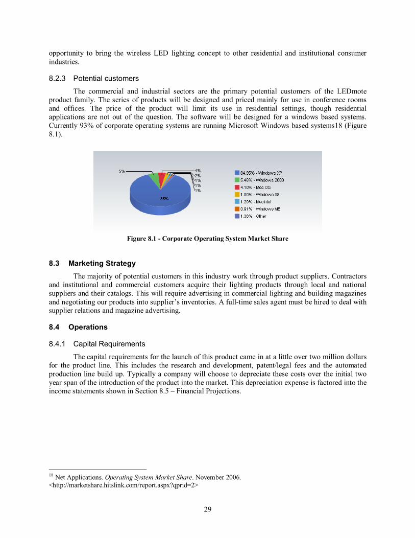
The commercial and industrial sectors are the primary potential customers of the LEDmote product family. The series of products will be designed and priced mainly for use in conference rooms and offices. The price of the product will limit its use in residential settings, though residential applications are not out of the question. The software will be designed for a windows based systems. Currently 93% of corporate operating systems are running Microsoft Windows based systems18 (Figure 8.1).
Figure 8.1 - Corporate Operating System Market Share
8.3 Marketing Strategy The majority of potential customers in this industry work through product suppliers. Contractors
and institutional and commercial customers acquire their lighting products through local and national suppliers and their catalogs. This will require advertising in commercial lighting and building magazines and negotiating our products into supplier�s inventories. A full-time sales agent must be hired to deal with supplier relations and magazine advertising.
8.4 Operations
8.4.1 Capital Requirements
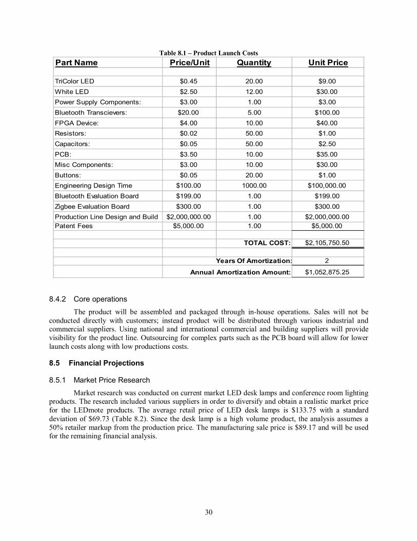
The capital requirements for the launch of this product came in at a little over two million dollars for the product line. This includes the research and development, patent/legal fees and the automated production line build up. Typically a company will choose to depreciate these costs over the initial two year span of the introduction of the product into the market. This depreciation expense is factored into the income statements shown in Section 8.5 � Financial Projections.
18 Net Applications. Operating System Market Share. November 2006. <http://marketshare.hitslink.com/report.aspx?qprid=2>
30
Table 8.1 � Product Launch Costs Part Name Price/Unit Quantity Unit Price
The product will be assembled and packaged through in-house operations. Sales will not be conducted directly with customers; instead product will be distributed through various industrial and commercial suppliers. Using national and international commercial and building suppliers will provide visibility for the product line. Outsourcing for complex parts such as the PCB board will allow for lower launch costs along with low productions costs.
8.5 Financial Projections
8.5.1 Market Price Research
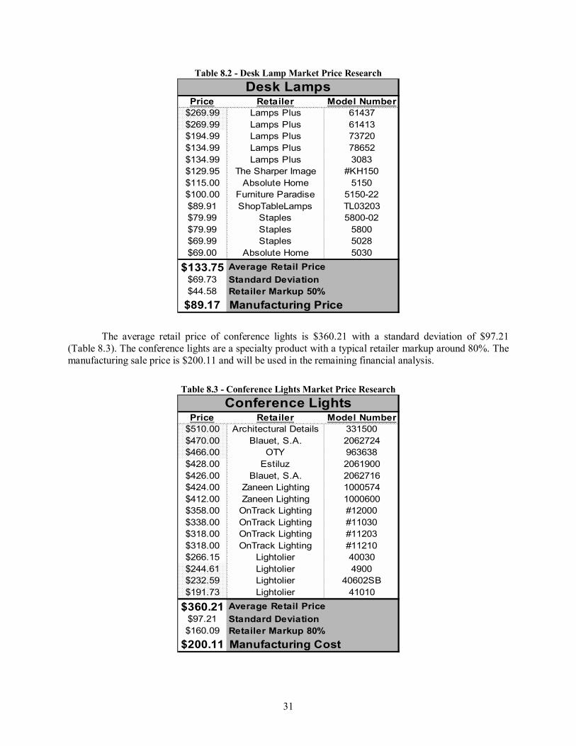
Market research was conducted on current market LED desk lamps and conference room lighting products. The research included various suppliers in order to diversify and obtain a realistic market price for the LEDmote products. The average retail price of LED desk lamps is $133.75 with a standard deviation of $69.73 (Table 8.2). Since the desk lamp is a high volume product, the analysis assumes a 50% retailer markup from the production price. The manufacturing sale price is $89.17 and will be used for the remaining financial analysis.
31
Table 8.2 - Desk Lamp Market Price Research
Price Retailer Model Number$269.99 Lamps Plus 61437$269.99 Lamps Plus 61413$194.99 Lamps Plus 73720$134.99 Lamps Plus 78652$134.99 Lamps Plus 3083$129.95 The Sharper Image #KH150$115.00 Absolute Home 5150$100.00 Furniture Paradise 5150-22$89.91 ShopTableLamps TL03203$79.99 Staples 5800-02$79.99 Staples 5800$69.99 Staples 5028$69.00 Absolute Home 5030
$133.75 Average Retail Price$69.73 Standard Deviation$44.58 Retailer Markup 50%
$89.17 Manufacturing Price
Desk Lamps
The average retail price of conference lights is $360.21 with a standard deviation of $97.21 (Table 8.3). The conference lights are a specialty product with a typical retailer markup around 80%. The manufacturing sale price is $200.11 and will be used in the remaining financial analysis.
Table 8.3 - Conference Lights Market Price Research
$360.21 Average Retail Price$97.21 Standard Deviation$160.09 Retailer Markup 80%
$200.11 Manufacturing Cost
Conference Lights
32
8.5.2 Production Cost Analysis
The desk lamp production cost breakdown is shown in Table 8.4 below. The lamp fixture itself contains LEDs, material and miscellaneous components. Team LEDmote is not designing the fixture itself so the material component price aspect is an estimate based on Innotec�s input. The lamp controls pricing section consists of the Bluetooth and FPGA device along with various other minor components. A miscellaneous components section is included to account for parts that have not yet been accounted for. Finally labor, shipping, packaging is included into the price giving a total cost of $72.98 per unit sold.
Table 8.4 - Desk Lamp Cost Analysis
Part Name Price/Unit Quantity Per Unit Unit Price
LAMP FIXTURE:TriColor LED $0.45 10.00 $4.50White LED $2.50 5.00 $12.50Material $15.00 1.00 $15.00
TYPICAL NUMBER OF COMPONENTS PER UNIT:Lamp Fixture: $32.00 1.00 $32.00Labor: $12.00 0.04 $0.48Packaging: $1.00 1.00 $1.00Shipping: $2.00 1.00 $2.00Lamp Controls: $37.50 1.00 $37.50
TOTAL COST OF GOODS SOLD: $72.98
DESK LAMP LIGHTING PRODUCTION COST ANALYSIS
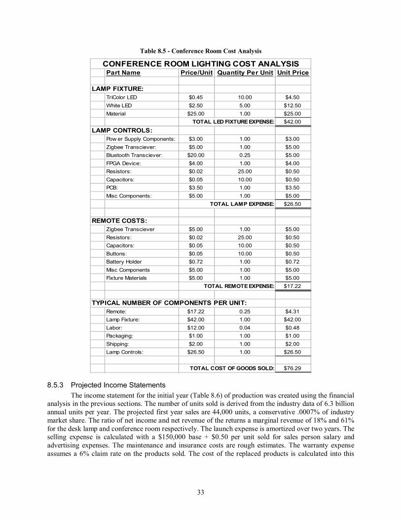
The conference lighting production cost breakdown is shown in Table 8.5 below. The lamp fixture itself contains LED, material and miscellaneous components. Team LEDmote is not designing the fixture itself so the material component price aspect is an estimate based on Innotec�s input. It is higher then the desk lamp given the built-in aesthetics that will be required and the size of the conference room lamp fixtures. The lamp controls pricing section consists of the Zigbee transceiver, FPGA device, minor components and one fourth of the Bluetooth module cost. A miscellaneous components section is included to take into account for parts that we did not account for in the design. We are assuming that the typical conference room will have one remote, one mother lamp with dual wireless technologies (i.e. Zigbee and Bluetooth) and three slave lamps. Therefore the single unit cost includes one fourth of the remote and Bluetooth module. Finally labor, shipping, packaging, and one forth remote cost are included into the price giving a total cost of $76.29.
33
Table 8.5 - Conference Room Cost Analysis
Part Name Price/Unit Quantity Per Unit Unit Price
LAMP FIXTURE:TriColor LED $0.45 10.00 $4.50White LED $2.50 5.00 $12.50Material $25.00 1.00 $25.00
TYPICAL NUMBER OF COMPONENTS PER UNIT:Remote: $17.22 0.25 $4.31Lamp Fixture: $42.00 1.00 $42.00Labor: $12.00 0.04 $0.48Packaging: $1.00 1.00 $1.00Shipping: $2.00 1.00 $2.00Lamp Controls: $26.50 1.00 $26.50
TOTAL COST OF GOODS SOLD: $76.29
CONFERENCE ROOM LIGHTING COST ANALYSIS
8.5.3 Projected Income Statements The income statement for the initial year (Table 8.6) of production was created using the financial
analysis in the previous sections. The number of units sold is derived from the industry data of 6.3 billion annual units per year. The projected first year sales are 44,000 units, a conservative .0007% of industry market share. The ratio of net income and net revenue of the returns a marginal revenue of 18% and 61% for the desk lamp and conference room respectively. The launch expense is amortized over two years. The selling expense is calculated with a $150,000 base + $0.50 per unit sold for sales person salary and advertising expenses. The maintenance and insurance costs are rough estimates. The warranty expense assumes a 6% claim rate on the products sold. The cost of the replaced products is calculated into this
34
warranty expense. The first year of production shows a net loss of $197,838.69, which is typical for a product launch.
Table 8.6 - First Year Income Statement
DESK LAMP:Number of Units: 40,000Sales:
Price Per Unit: 89.17$ Desk Lamp Revenue: 3,566,728.21$
COGS: (2,919,200.00)$ Desk Lamp Net Income: 647,528.21$
CONFERENCE ROOM:Number of Units: 4,000Sales:
Price Per Unit: 200.11$ Conference Room Revenue: 800,456.30$
COGS: (309,140.00)$ Conference Room Net Income: 491,316.30$
Total Expenses: (1,468,575.65)$ NET INCOME BEFORE TAXES: (329,731.15)$
Income Tax: 131,892.46$ NET INCOME: (197,838.69)$
LEDmotePRODUCT LAUNCH INCOME STATEMENT
FIRST YEAR STATEMENT
The second year income statement (Table 8.7) was created using the financial analysis from the research and projections in the previous sections. The number of units sold increases from the previous from product exposure and advertising. The projected second year sales are 68,000 units, still a conservative .00105% of industry market share. The sale price of the units is decreased by 5% to account for inflation and maturity of the product. The marginal revenue percentage of the desk lamp is 14%. The marginal revenue percentage of the conference room is 59%. The final installment of the launch amortized expense is reflected in year two.. The selling expense is calculated with a set $120,000 base fee + $0.50 per unit sold for sales person salary and advertising expenses. The warranty expense assumes a 5% claim rate on the products sold. The cost of the replaced products is calculated into this warranty expense. The product line produces a net profit of $59,787.24 in its second year.
35
Table 8.7- Second Year Income Statement
DESK LAMP:Number of Units: 60,000Sales:
Price Per Unit: 84.71$ Desk Lamp Revenue: 5,082,587.69$
COGS: (4,378,800.00)$ Desk Lamp Net Income: 703,787.69$
CONFERENCE ROOM:Number of Units: 8,000Sales:
Price Per Unit: 190.11$ Conference Room Revenue: 1,520,866.96$
COGS: (618,280.00)$ Conference Room Net Income: 902,586.96$
Total Expenses: (1,506,729.25)$ NET INCOME BEFORE TAXES: 99,645.41$
Income Tax: (39,858.16)$ NET INCOME: 59,787.24$
LEDmotePRODUCT LAUNCH INCOME STATEMENT
SECOND YEAR STATEMENT
The third year income statement (Table 8.8) was created using the financial analysis from the research and projections in the previous sections. The number of units sold increased from the previous terms due to product exposure and advertising. The projected second year sales are 110,000 units, still a conservative .00169% industry market share. The sale price of the units is decreased by 15% from the original price to account for inflation and to keep the product competitive. Additionally the cost of goods sold was decrease by 5% to account for improvements in production efficiency and decrease in component costs. The marginal revenue percentage of the desk lamp is 4%. The marginal revenue percentage of the conference room is 54%. The launch expense is fully amortized leaving no launch expense for the third year. The selling expense is calculated with a $100,000 base + $0.50 per unit sold for sales person salary and advertising expenses. The warranty expense assumes a 4% claim rate on the products sold. The claim rate is decreasing due to more efficient processes and decrease PPM. The cost of the replaced products is calculated into this warranty expense. The product line produces a net profit of $627,889.84 in the third year. The third year final statement reflects closely the sustainable income from this product line into the future years.
36
Table 8.8- Third Year Income Statement
DESK LAMP:Number of Units: 100,000Sales:
Price Per Unit: 75.79$ Desk Lamp Revenue: 7,579,297.44$
COGS: (6,933,100.00)$ Desk Lamp Net Income: 646,197.44$
CONFERENCE ROOM:Number of Units: 10,000Sales:
Price Per Unit: 170.10$ Conference Room Revenue: 1,700,969.63$
COGS: (772,850.00)$ Conference Room Net Income: 928,119.63$
Total Expenses: (527,834.00)$ NET INCOME BEFORE TAXES: 1,046,483.07$
Income Tax: (418,593.23)$ NET INCOME: 627,889.84$
LEDmotePRODUCT LAUNCH INCOME STATEMENT
THIRD YEAR STATEMENT
9 Feasibility The LEDmote project shows feasibility in many areas. Market research shows high sales potential
with low market entry costs. Cost analysis shows that production of a competitive product is feasible. Innotec�s agreement to purchase components for the prototype and design costs along with the school�s budget ensures financial feasibility. The technical aspects of the design are well within the bounds of the teams capabilities. With good project management and the proper scheduling the project can be accomplished in a timely fashion.
9.1 Technical Feasibility The analysis described in this project feasibility study show that the project is certainly
technically feasible. None of the technical aspects of the project appear to be beyond the team�s capabilities. The team�s potential problems have been carefully examined and addressed. The current test plan will greatly assist the development of the prototype by minimizing accidents that might delay the project�s schedule.
37
9.2 Schedule Feasibility The schedule analysis has been broken up into separate components of the project. This allows
the team to better itemize every task and show a clear time break down for each aspect of the project. The time estimates are rough guesses with padding to account for time underestimations. The total hours of the project are shown below in Figure 9.1.
113
110
132
167142
159
182
Overall Project TasksRemote ControlWirelessControl ICPower SupplySoftwareDocumentation and Media
The total project time is projected to take about 1000 hours. This amount of time is typical in relation to previous senior design projects. The project schedules (Appendix II) were developed with several clear objectives in mind. The first objective laid out a structured and organized project plan. The second objective set goals to stay ahead the entire year. The final objective made sure that deadlines were met.
The schedule is broken down into several hierarchical blocks. Each block contains a year-long central topic and smaller subtopics that span from 1 week up to 1½ months. The subtopic is broken down into tasks. The tasks ranged from 1 day to 2 weeks of time. This structure gives the team clear tasks to work on and through the Microsoft Project diagrams, a timeframe in which each task is due. The task start dates are set early enough to complete every task in a timely manner and prevent bottlenecks for any future tasks.
38
9.2.1 System Level Project Tasks
Table 9.2� System Level Timing Analysis
Kreft Prince Truer VeldkampOverall Project Tasks 123 58 May 03, 2007
Research November 24, 2006Feasability Research 5 3 2 2.5 7.5 October 27, 2006Design Research 5 2 2 2 1 7 November 24, 2006
Decision Matrix November 17, 2006Alernatives 5 2 4 1.5 7.5 November 04, 2006Criteria 5 1 3 1 5 November 04, 2006Create Decision Matrix 8 4 3 1 8 November 17, 2006
Block Diagram November 17, 2006I/O 2 1 3 4 October 27, 2006Layout 2 1 3 4 November 17, 2006Design 2 1 1 2 December 15, 2006Parts 2 3 3 December 01, 2006Schematics 4 0 December 08, 2006Requirement Check 5 0 December 15, 2006
Order Parts January 30, 2007Find Parts 10 2 1.5 2 3 8.5 November 24, 2006Pick Manufacturer 1 1.5 1.5 November 24, 2006Submit Order 1 0 December 15, 2006Receive 0 0 January 30, 2007
Breadboard February 13, 2007Breadboard Small Projects 10 0 January 26, 2007Breadboard Entire Project 10 0 February 13, 2007
Testing February 26, 2007Develop Test Plan 2 0 January 16, 2007Implement Test Plan and Record Results 2 0 February 26, 2007
Debug March 20, 2007Research Solutions 4 0 March 20, 2007Implement and Test 5 0 March 20, 2007
Printed Circuit Board April 16, 2007Arrange Layout 15 0 March 16, 2007Order PCB 1 0 March 23, 2007Receive PCB 0 0 April 16, 2007
Assemble Prototype May 03, 2007Assemble on PCB 7 0 April 23, 2007Problem Solve 10 0 May 03, 2007
Actual Total Hours Due DatesTask Descriptions
Predicted Hours
Actual Individual Hours
39
9.2.2 Remote Control Table 9.3- Remote Control Timing Analysis
Kreft Prince Truer VeldkampRemote Control 114 32.5 April 11, 2007
Research November 16, 2006Feasability Research 5 1 5 6 October 17, 2006Design Research 8 2 4 1 7 November 16, 2006
Decision Matrix November 13, 2006Alernatives 5 2 4 1 7 October 27, 2006Criteria 5 1.5 0.5 2 0.5 4.5 October 27, 2006Create Decision Matrix 3 2 2 1 5 November 13, 2006
Block Diagram November 22, 2006I/O 5 1 1 November 06, 2006Layout 5 2 2 November 22, 2006
Design December 08, 2006Parts 10 0 November 27, 2006Schematics 12 0 December 05, 2006Requirement Check 4 0 December 08, 2006
Order Parts January 12, 2007Find Parts 4 0 November 24, 2006Pick Manufacturer 2 0 November 24, 2006Submit Order 1 0 December 11, 2006Receive 0 0 January 12, 2007
Breadboard January 16, 2007Breadboard Remote Control 3 0 January 16, 2007
Testing February 02, 2007Develop Test Plan 2 0 January 16, 2007Implement test Plan and Record Results 5 0 February 02, 2007
Debug February 26, 2007Research Solutions 5 0 February 26, 2007Implement and Test 5 0 February 26, 2007
Printed Circuit Board March 26, 2007Arrange Layout 8 0 February 28, 2007Order PCB 1 0 March 07, 2007Receive PCB 0 0 March 26, 2007
Assemble Prototype April 11, 2007Assemble on PCB 4 0 April 02, 2007Problem Solve 12 0 April 11, 2007
Actual Total Hours Due DatesTask Descriptions
Predicted Hours
Actual Individual Hours
40
9.2.3 Wireless
Table 9.4 - Wireless Timing Analysis
Kreft Prince Truer VeldkampWireless 135 39.5 April 11, 2007
Research November 16, 2006Feasability Research 10 2 2 3 3 10 October 17, 2006Design Research 12 2 1 4.5 2 9.5 November 16, 2006
Decision Matrix November 13, 2006Alernatives 3 4 1 1 6 October 27, 2006Criteria 4 1 2 1 1 5 October 27, 2006Create Decision Matrix 2 2.5 1 1 4.5 November 13, 2006
Block Diagram November 22, 2006I/O 2 0.5 0.5 1 0.5 2.5 November 06, 2006Layout 4 0 November 22, 2006
Design December 08, 2006Parts 4 0 November 27, 2006Schematics 7 0 December 05, 2006Requirement Check 3 0 December 08, 2006
Order Parts January 12, 2007Find Parts 3 1 1 November 24, 2006Pick Manufacturer 2 0 November 24, 2006Submit Order 1 1 1 December 11, 2006Receive 0 0 January 12, 2007
Breadboard January 16, 2007Breadboard Wireless 5 0 January 16, 2007
Testing February 02, 2007Develop Test Plan 5 0 January 16, 2007Implement test Plan and Record Results 5 0 February 02, 2007Debug 9 0 February 26, 2007Research Solutions 5 0 February 26, 2007Implement and Test 10 0 February 26, 2007
Printed Circuit Board March 26, 2007Arrange Layout 12 0 February 28, 2007Order PCB 2 0 March 07, 2007Receive PCB 0 0 March 26, 2007
Assemble Prototype April 11, 2007Assemble on PCB 10 0 April 02, 2007Problem Solve 15 0 April 11, 2007
Actual Total Hours Due DatesTask Descriptions
Predicted Hours
Actual Individual Hours
41
9.2.4 Control IC Table 9.5- Control IC Timing Analysis
Kreft Prince Truer VeldkampControl IC 161 41 April 11, 2007
Research November 16, 2006Feasability Research 15 3 2 3 4 12 October 17, 2006Design Research 15 2 3 3 3 11 November 16, 2006
Decision Matrix November 13, 2006Alernatives 5 2 1 1 2 6 October 27, 2006Criteria 4 1 1 1 2 5 October 27, 2006Create Decision Matrix 3 3 3 November 13, 2006
Block Diagram November 22, 2006I/O 5 1 2 3 November 06, 2006Layout 8 1 1 November 22, 2006
Design December 08, 2006Parts 5 0 November 27, 2006Schematics 5 0 December 05, 2006Requirement Check 4 0 December 08, 2006
Order Parts January 12, 2007Find Parts 8 0 November 24, 2006Pick Manufacturer 4 0 November 24, 2006Submit Order 5 0 December 11, 2006Receive 0 0 January 12, 2007
Breadboard January 16, 2007Breadboard Control 10 0 January 16, 2007
Testing February 02, 2007Develop Test Plan 6 0 January 16, 2007Implement test Plan and Record Results 7 0 February 02, 2007Debug 10 0 February 26, 2007Research Solutions 8 0 February 26, 2007Implement and Test 9 0 February 26, 2007
Assemble Prototype April 11, 2007Assemble on PCB 10 0 April 02, 2007Problem Solve 15 0 April 11, 2007
Actual Total Hours Due DatesTask Descriptions
Predicted Hours
Actual Individual Hours
42
9.2.5 Power Supply Table 9.6- Power supply time analysis
Kreft Prince Truer VeldkampPower Supply 144 33.5 April 11, 2007
Research November 16, 2006Feasability Research 10 7 1 2 0.5 10.5 October 17, 2006Design Research 10 6 2 1 9 November 16, 2006
Decision Matrix November 13, 2006Alernatives 5 3 1 1 1 6 October 27, 2006Criteria 3 2 1 1 4 October 27, 2006Create Decision Matrix 2 2 2 November 13, 2006
Block Diagram November 22, 2006I/O 4 2 2 November 06, 2006Layout 5 0 November 22, 2006Design 5 0 December 08, 2006Parts 4 0 November 27, 2006Schematics 6 0 December 05, 2006Requirement Check 3 0 December 08, 2006
Order Parts January 12, 2007Find Parts 4 0 November 24, 2006Pick Manufacturer 5 0 November 24, 2006Submit Order 2 0 December 11, 2006Receive 0 0 January 12, 2007
Breadboard January 16, 2007Breadboard Power Supply 7 0 January 16, 2007
Testing February 02, 2007Develop Test Plan 5 0 January 16, 2007Implement test Plan and Record Results 5 0 February 02, 2007Debug 9 0 February 26, 2007Research Solutions 5 0 February 26, 2007Implement and Test 10 0 February 26, 2007
Printed Circuit Board March 26, 2007Arrange Layout 10 0 February 28, 2007Order PCB 2 0 March 07, 2007Receive PCB 0 0 March 26, 2007
Assemble Prototype April 11, 2007Assemble on PCB 8 0 April 02, 2007Problem Solve 15 0 April 11, 2007
Kreft Prince Truer VeldkampSoftware 184 19 April 11, 2007
Research 0 December 16, 2006Feasability Research 15 6 6 December 02, 2006Design Research 15 2 2 December 15, 2006
Decision Matrix November 15, 2006Alernatives 8 2 2 November 02, 2006Criteria 4 7 7 November 15, 2006Create Decision Matrix 3 1 1 November 15, 2006
Software Architecture February 10, 2007Architecture Layout 3 1 1 December 15, 2006Breakdown blocks 6 0 February 10, 2007
Testing April 01, 2007Develop Test Plan 5 0 February 15, 2007Implement test Plan and Record Results 10 0 February 20, 2007Debug 10 0 March 15, 2007Research Solutions 10 0 March 20, 2007Implement and Test 10 0 April 01, 2007
Coding April 01, 2007Develop GUI 30 0 February 23, 2007Link to Bluetooth 20 0 March 15, 2007Combine Software 5 0 April 01, 2007
Assemble Prototype April 15, 2007Execute with System 10 0 March 23, 2007Problem Solve 20 0 April 30, 2007
Actual Total Hours Due DatesTask Descriptions
Predicted Hours
Actual Individual Hours
9.2.7 Documentation and Media Table 9.8- Documentation and Media Timing Analysis
Kreft Prince Truer VeldkampDocumentation and Media 263 108.5 May 11, 2007
Objectives 2 2 1 3 October 13, 2006Poster 1 2 2 2 October 11, 2006Presentation 1 3 8 8 October 13, 2006Preliminary Task Specification 2 0 October 20, 2006Website 4 6 6 October 20, 2006Preliminary Feasibility Study 5 1.5 1.5 October 27, 2006Preliminary Budget 4 7 7 October 30, 2006Revised Task Specification 4 4 4 November 02, 2006Preliminary Project Schedule 6 5 6 11 November 06, 2006Brief for Industrial Consultant 6 2 2 4 November 10, 2006Preliminary PPFS 50 12.5 0.5 8 21 November 27, 2006Presentation 2 6 0 November 27, 2006Final PPFS 25 0 December 08, 2006Presentation 3 6 0 March 23, 2007Poster 2 3 0 April 20, 2007Preliminary Design Report 2 0 April 20, 2007Final Design Report 5 0 May 11, 2007Presentation 4 25 0 May 11, 2007Top Rock Meetings 80 9 9 9 9 36Devotions 2 2 2Faculty Design Review 1 0Mentor Corresponding 20 3 3
Actual Total Hours Due DatesTask Descriptions
Predicted Hours
Actual Individual Hours
44
10 Acknowledgements Team LEDmote has received assistance on the project from numerous professional sources. The
team would like to thank professors Paulo Ribeiro, Ph. D and Randy Brouwer, Ph. D for their input and provision of resources for, respectively, designing a power supply and an amplification stage for our project. The team would also like to thank Steven H. VanderLeest, Ph. D for guiding the team at crucial points in the project, for expanding our thinking on design alternatives and for giving us encouragement. The team is obligated to Mr. Tom Veenstra for agreeing to mentor the project, for being a liaison with Innotec for resources, requirements and funding for the project. Finally, the team owes its gratitude to Mr. Tim Theriault of Smiths Aerospace, the team�s industrial consultant, for giving his time to review the project and for providing new insights and possibilities.
11 Conclusion Through the careful analysis of this study, team LEDmote has concluded that the proposed
project is feasible in terms of both time and money. Funding is to be provided from Innotec in the near future, and the team has begun ordering parts to begin building a prototype next semester. The team has full confidence that a working prototype complete with a comprehensive design review will be available for Innotec by May 2007.