QSPXM Manual QSPXM Installation and Programming Manual This Manual describes the QSPXM (Quantum Seriplex Master), its uses and set up. Effective: 13 November, 2002 Niobrara Research & Development Corporation P.O. Box 3418 Joplin, MO 64803 USA Telephone: (800) 235-6723 or (417) 624-8918 Facsimile: (417) 624-8920 Internet: http://www.niobrara.com
Transcript
QSPXM Manual
QSPXMInstallation and Programming Manual
This Manual describes the QSPXM (Quantum Seriplex Master), its uses and set up.
Effective: 13 November, 2002
Niobrara Research & Development CorporationP.O. Box 3418 Joplin, MO 64803 USA
Telephone: (800) 235-6723 or (417) 624-8918Facsimile: (417) 624-8920Internet: http://www.niobrara.com
Seriplex, SY/MAX, and Square D are registered trademarks of Square D Company.
Modbus, Modbus Plus, Modicon, Modsoft, Quantum Automation Series are trademarks of SchneiderAutomation Inc.
Example 1, Simple Analog Configuration ...................................................................15Example 2, Simple Discrete Configuration ..................................................................17Example 3, Multiplexed System ..................................................................................18
V OK off .......................................................................................................................25Fault ..............................................................................................................................25
Appendix A NR&D Internet ............................................................................. 27
Appendix B Modsoft Traffic Cop Configuration .............................. 29
4
Figures
Figure 1-1 QSPXM Front Panel .....................................................................................................7
Figure 3-1 Example 1 ...................................................................................................................15
Figure 3-2 Example 1 Ladder Code .............................................................................................16
Figure 3-3 Example 2 ...................................................................................................................17
Figure 3-4 Example 2 Ladder Code .............................................................................................18
Figure 3-5 Example 3 ...................................................................................................................19
Table 3-1 Example 1 4x Configuration Register ..........................................................................16
Table 3-2 Example 1 Register List ...............................................................................................16
Table 3-3 Example 2 0x Configuration Register ..........................................................................18
Table 3-4 Example 2 Bit List .......................................................................................................18
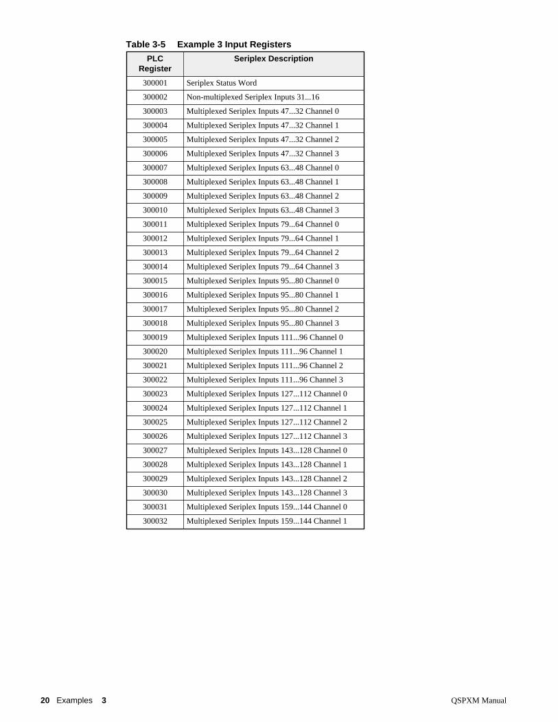
Table 3-5 Example 3 Input Registers ...........................................................................................20
Table 3-6 Example 3 Output Registers ........................................................................................21
QSPXM Manual 1 Introduction 5
1
Introduction
The Niobrara QSPXM allows a Modicon TSX Quantum Automation Series PLC to interact with I/Opoints and devices via the Seriplex Sensor/Actuator bus. Seriplex is an efficient, inexpensive, determi-nistic bus interconnecting up to 255 I/O points or 240 16-bit words using a four wire cable. TheQSPXM supports both Seriplex Mode 1 (peer-to-peer) and Mode 2 (host-controlled) configurations.
The QSPXM contains Seriplex technology and conforms to the latest Seriplex standard. The QSPXMconnects to the Seriplex cable through a front-mounted, male 9 pin D-subminiature connector. AllSeriplex circuits are optically isolated from PLC electronics.
An external power supply is required. Only one host interface (such as QSPXM) at a time should beconnected to the Seriplex bus and no clock module should be connected when the QSPXM is used. TheQSPXM supplies the Seriplex clock and sources pull-up current to the Seriplex data line.
The QSPXM interfaces to the Quantum PLC as an I/O module and is thus permitted to be used in theLocal (CPU rack), Remote (RIO), or Distributed (DIO) I/O racks1. The QSPXM is Traffic Copped asan analog module with up to 32 Input (3xxxxx) registers and 32 Output (4xxxxx) registers, or as a dis-crete module with up to 512 input bits (1xxxxx) and 512 coils (0xxxxx). The first of these Output regis-ters (16 bits) configures the QSPXM and the others are mapped to Seriplex peripherals. The first of theInput registers (16 bits) provides a bit-map of the status of the QSPXM. The layout of the I/O registersdepends on the configuration register value. The QSPXM supports lengths of the Seriplex bus up to 256bits in multiples of 16. The QSPXM supports multiplexing of 2, 4, 8, or 16 channels deep by up to 240bits wide in multiples of 16 bits. Multiplexed words must be positioned on 16 bit boundaries and mustoccupy the highest numbered bits of the configured Seriplex address space.
SpecificationsMounting Requirements
One slot of Quantum backplane.
Maximum Required Addressing32 Words In32 words Out
Current Draw on Quantum Rack power supply 100 mA max. (35-50mA typical)
1 The Local and RIO racks will support the full 32 words In and 32 words Out. The DIO interface will only support a maximumof 30 words In and 32 words Out. The GCNTFCOP.SYS file for Modsoft must be modified for use with the DIO. See Appen-dix B on page 29 for more information.
6 Introduction 1 QSPXM Manual
Operating Temperature0 to 60 degrees C operating. -40 to 80 degrees C storage.
Humidity Rating up to 90% noncondensing
Pressure Altitude-200 to +10,000 feet MSL
Seriplex Communication Port9 pin male D-connector. Variable frequency (16, 32, 64, 100) Kbaud Seriplexprotocol. Supports Mode 1 and Mode 2 and Multiplexed analog I/O.
Indicator lights6 LEDs: Green Active, Green Ready, Green Run, Green Voltage OK, Green Data Val (CDR ON) , and Red Fault
Seriplex Connector - DE9 maleconnector for the Seriplex bus.
Pin Function
1 No Connection (Shield)
2,6 Seriplex Common
3,7 Seriplex power, +12 or +24VDC
4,8 Seriplex clock
5,9 Seriplex data
140QSPXMNiobrara
Removable Door
LED Area
Module NumberModule DescriptionColor Code
QSPXM Manual 2 Installation 9
2
Installation
Module InstallationNote: Like all Quantum modules, the QSPXM may be hot swapped. It is not necessary to removepower to the rack to remove or install the QSPXM.
1 Mount the QSPXM at an angle onto the two hooks near the top of the backplane slot. Rotate themodule down to make electrical contact to the backplane. Secure the screw at the bottom of themodule.
2 With power applied to the rack, all LEDs should strobe and when finished, the green Ready LEDshould illuminate and remain lit. This indicates that the QSPXM has passed its internal self checksand is ready.
3 If the Quantum CPU is in RUN, the green Active LED should illuminate. The green RUN LEDwill come on only when a valid configuration is loaded in the first output register and there are noSeriplex fault conditions.
4 The green V OK LED will be OFF to indicate an undervoltage on the Seriplex network. This lightwill come on when the Seriplex network is properly connected.
Seriplex installation
Seriplex Connector
The QSPXM connects to the Seriplex network using its 9 pin port. The pinout of this connector and thesuggested wire colors for the Seriplex network cable is shown in Table 2-1.
Table 2-1 QSPXM Seriplex Connector
Pin Function Suggested Wire Color
1 No Connection (Shield) Bare
2,6 Seriplex Common Black
3,7 Seriplex power, +12 or +24VDC Red
4,8 Seriplex clock Green or Blue
5,9 Seriplex data White
10 Installation 2 QSPXM Manual
Seriplex Power Supply
An isolated 24VDC (or optionally 12VDC) power supply is required for the Seriplex network. Thepower supply requirements are listed in Table 2-2. It is recommended that the current capacity be ratedat 1.2 times the total load current of the network. Also, long cable runs may result in voltage drop, somultiple power supplies may need to be included in the network.
Table 2-2 Seriplex 24V Power Supply Requirements
Seriplex Clock Module
The QSPXM provides the clock signal for the Seriplex network in Mode 1 and Mode 2.
NOTE: Any external clock module is not required and should NOT be used.
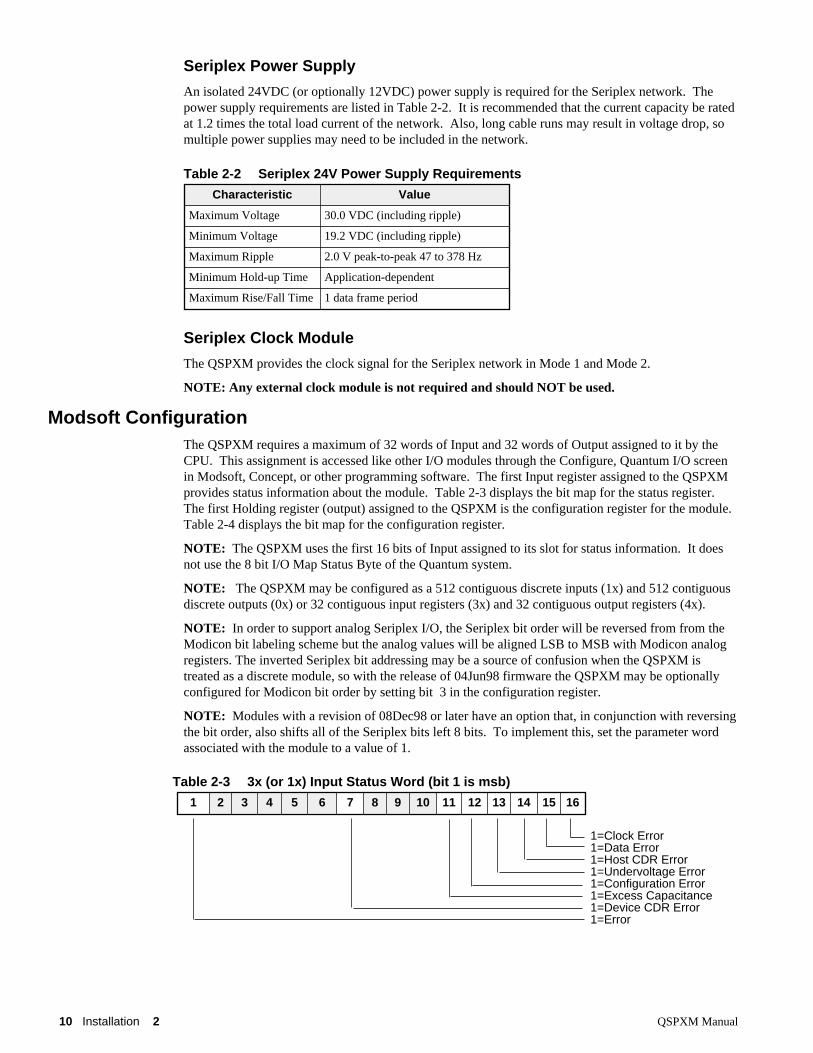
Modsoft ConfigurationThe QSPXM requires a maximum of 32 words of Input and 32 words of Output assigned to it by theCPU. This assignment is accessed like other I/O modules through the Configure, Quantum I/O screenin Modsoft, Concept, or other programming software. The first Input register assigned to the QSPXMprovides status information about the module. Table 2-3 displays the bit map for the status register. The first Holding register (output) assigned to the QSPXM is the configuration register for the module. Table 2-4 displays the bit map for the configuration register.
NOTE: The QSPXM uses the first 16 bits of Input assigned to its slot for status information. It doesnot use the 8 bit I/O Map Status Byte of the Quantum system.
NOTE: The QSPXM may be configured as a 512 contiguous discrete inputs (1x) and 512 contiguousdiscrete outputs (0x) or 32 contiguous input registers (3x) and 32 contiguous output registers (4x).
NOTE: In order to support analog Seriplex I/O, the Seriplex bit order will be reversed from from theModicon bit labeling scheme but the analog values will be aligned LSB to MSB with Modicon analogregisters. The inverted Seriplex bit addressing may be a source of confusion when the QSPXM istreated as a discrete module, so with the release of 04Jun98 firmware the QSPXM may be optionallyconfigured for Modicon bit order by setting bit 3 in the configuration register.
NOTE: Modules with a revision of 08Dec98 or later have an option that, in conjunction with reversingthe bit order, also shifts all of the Seriplex bits left 8 bits. To implement this, set the parameter wordassociated with the module to a value of 1.
Characteristic Value
Maximum Voltage 30.0 VDC (including ripple)
Minimum Voltage 19.2 VDC (including ripple)
Maximum Ripple 2.0 V peak-to-peak 47 to 378 Hz
Minimum Hold-up Time Application-dependent
Maximum Rise/Fall Time 1 data frame period
Table 2-3 3x (or 1x) Input Status Word (bit 1 is msb)
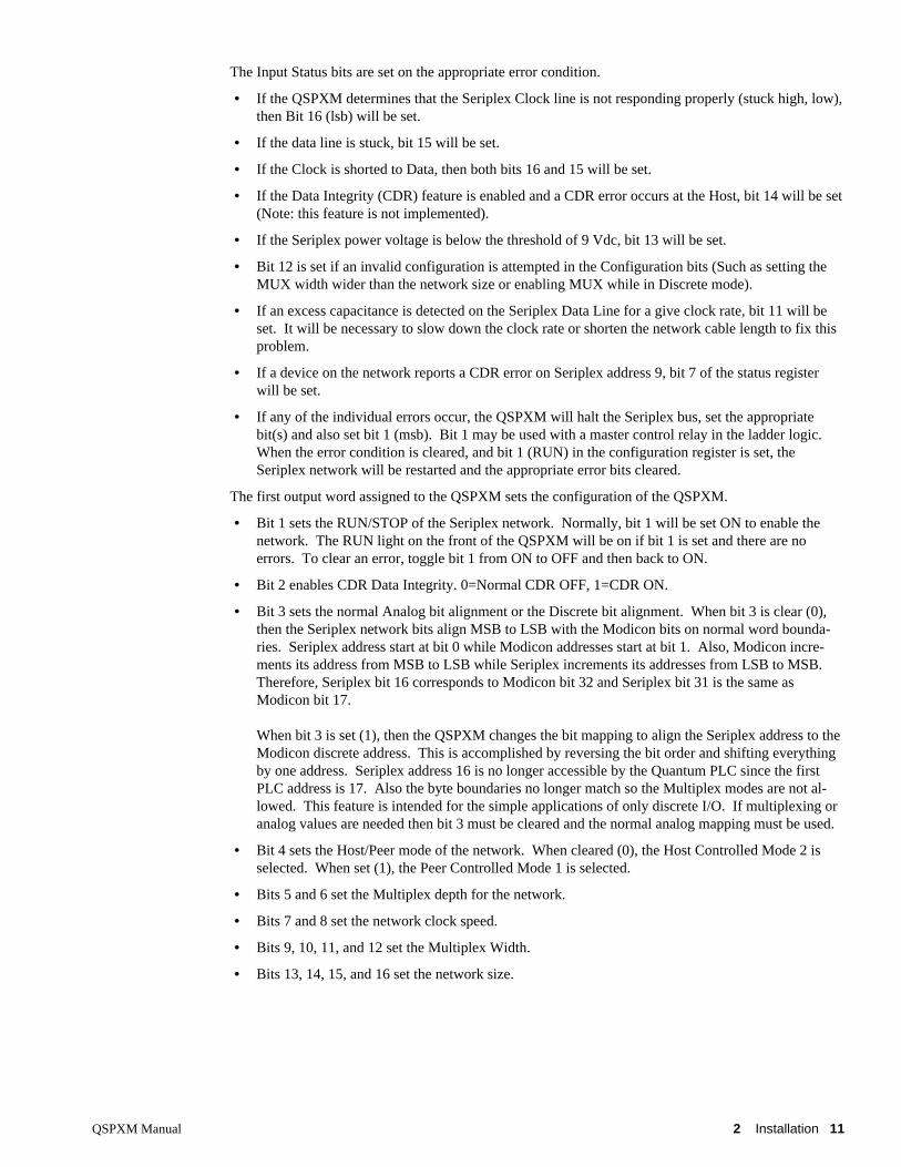
The Input Status bits are set on the appropriate error condition.
• If the QSPXM determines that the Seriplex Clock line is not responding properly (stuck high, low),then Bit 16 (lsb) will be set.
• If the data line is stuck, bit 15 will be set.
• If the Clock is shorted to Data, then both bits 16 and 15 will be set.
• If the Data Integrity (CDR) feature is enabled and a CDR error occurs at the Host, bit 14 will be set(Note: this feature is not implemented).
• If the Seriplex power voltage is below the threshold of 9 Vdc, bit 13 will be set.
• Bit 12 is set if an invalid configuration is attempted in the Configuration bits (Such as setting theMUX width wider than the network size or enabling MUX while in Discrete mode).
• If an excess capacitance is detected on the Seriplex Data Line for a give clock rate, bit 11 will beset. It will be necessary to slow down the clock rate or shorten the network cable length to fix thisproblem.
• If a device on the network reports a CDR error on Seriplex address 9, bit 7 of the status registerwill be set.
• If any of the individual errors occur, the QSPXM will halt the Seriplex bus, set the appropriatebit(s) and also set bit 1 (msb). Bit 1 may be used with a master control relay in the ladder logic. When the error condition is cleared, and bit 1 (RUN) in the configuration register is set, theSeriplex network will be restarted and the appropriate error bits cleared.
The first output word assigned to the QSPXM sets the configuration of the QSPXM.
• Bit 1 sets the RUN/STOP of the Seriplex network. Normally, bit 1 will be set ON to enable thenetwork. The RUN light on the front of the QSPXM will be on if bit 1 is set and there are noerrors. To clear an error, toggle bit 1 from ON to OFF and then back to ON.
• Bit 2 enables CDR Data Integrity. 0=Normal CDR OFF, 1=CDR ON.
• Bit 3 sets the normal Analog bit alignment or the Discrete bit alignment. When bit 3 is clear (0),then the Seriplex network bits align MSB to LSB with the Modicon bits on normal word bounda-ries. Seriplex address start at bit 0 while Modicon addresses start at bit 1. Also, Modicon incre-ments its address from MSB to LSB while Seriplex increments its addresses from LSB to MSB. Therefore, Seriplex bit 16 corresponds to Modicon bit 32 and Seriplex bit 31 is the same asModicon bit 17.
When bit 3 is set (1), then the QSPXM changes the bit mapping to align the Seriplex address to theModicon discrete address. This is accomplished by reversing the bit order and shifting everythingby one address. Seriplex address 16 is no longer accessible by the Quantum PLC since the firstPLC address is 17. Also the byte boundaries no longer match so the Multiplex modes are not al-lowed. This feature is intended for the simple applications of only discrete I/O. If multiplexing oranalog values are needed then bit 3 must be cleared and the normal analog mapping must be used.
• Bit 4 sets the Host/Peer mode of the network. When cleared (0), the Host Controlled Mode 2 isselected. When set (1), the Peer Controlled Mode 1 is selected.
• Bits 5 and 6 set the Multiplex depth for the network.
• Bits 7 and 8 set the network clock speed.
• Bits 9, 10, 11, and 12 set the Multiplex Width.
• Bits 13, 14, 15, and 16 set the network size.
12 Installation 2 QSPXM Manual
The layout of the remaining registers of the QSPXM depends on the configuration. Following the con-figuration register and status register, there is one word for each non-multiplexed word (or fraction) ofI/O. In mode 2, the input register indicates the state of input points on the bus (even clock cycles) andthe output register determines the driven state of output modules (odd clock cycles). In mode 1, the in-put registers reflect the state of the Seriplex bits whether driven by modules on the bus or by theQSPXM and the output registers are wire-ored with field inputs occupying the same addresses.
NOTE: The QSPXM does not allow access to Seriplex bits 0 through 15. Registers 3x+1 and 4x+1start with Seriplex bits 16 through 31 inclusive. The bit order is aligned LSB to MSB with the Modiconanalog registers as shown in Tables 2-5 and 2-6 (Control Register bit 3 is OFF).
Table 2-4 4x (or 0x) Configuration Word (Bit 1 is msb)
0 0 0 0 Bus Size = 16 bits0 0 0 1 Bus Size = 32 bits0 0 1 0 Bus Size = 48 bits0 0 1 1 Bus Size = 64 bits0 1 0 0 Bus Size = 80 bits0 1 0 1 Bus Size = 96 bits0 1 1 0 Bus Size = 112 bits0 1 1 1 Bus Size = 128 bits1 0 0 0 Bus Size = 144 bits1 0 0 1 Bus Size = 160 bits1 0 1 0 Bus Size = 176 bits1 0 1 1 Bus Size = 192 bits1 1 0 0 Bus Size = 208 bits1 1 0 1 Bus Size = 224 bits1 1 1 0 Bus Size = 240 bits1 1 1 1 Bus Size = 256 bits
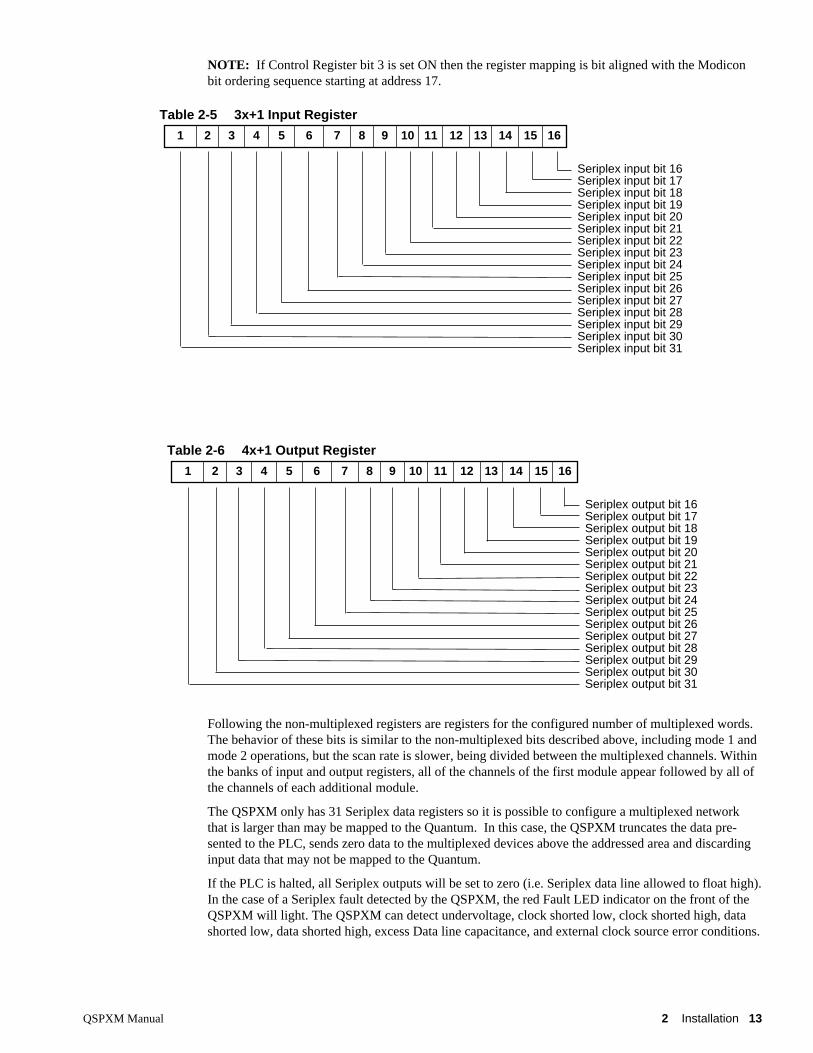
NOTE: If Control Register bit 3 is set ON then the register mapping is bit aligned with the Modiconbit ordering sequence starting at address 17.
Following the non-multiplexed registers are registers for the configured number of multiplexed words.The behavior of these bits is similar to the non-multiplexed bits described above, including mode 1 andmode 2 operations, but the scan rate is slower, being divided between the multiplexed channels. Withinthe banks of input and output registers, all of the channels of the first module appear followed by all ofthe channels of each additional module.
The QSPXM only has 31 Seriplex data registers so it is possible to configure a multiplexed networkthat is larger than may be mapped to the Quantum. In this case, the QSPXM truncates the data pre-sented to the PLC, sends zero data to the multiplexed devices above the addressed area and discardinginput data that may not be mapped to the Quantum.
If the PLC is halted, all Seriplex outputs will be set to zero (i.e. Seriplex data line allowed to float high).In the case of a Seriplex fault detected by the QSPXM, the red Fault LED indicator on the front of theQSPXM will light. The QSPXM can detect undervoltage, clock shorted low, clock shorted high, datashorted low, data shorted high, excess Data line capacitance, and external clock source error conditions.
Table 2-5 3x+1 Input Register
Seriplex input bit 16Seriplex input bit 17Seriplex input bit 18Seriplex input bit 19Seriplex input bit 20Seriplex input bit 21Seriplex input bit 22Seriplex input bit 23Seriplex input bit 24Seriplex input bit 25Seriplex input bit 26Seriplex input bit 27Seriplex input bit 28Seriplex input bit 29Seriplex input bit 30Seriplex input bit 31
1 2 3 4 5 6 7 8 9 10 11 12 13 14 15 16
Table 2-6 4x+1 Output Register
Seriplex output bit 16Seriplex output bit 17Seriplex output bit 18Seriplex output bit 19Seriplex output bit 20Seriplex output bit 21Seriplex output bit 22Seriplex output bit 23Seriplex output bit 24Seriplex output bit 25Seriplex output bit 26Seriplex output bit 27Seriplex output bit 28Seriplex output bit 29Seriplex output bit 30Seriplex output bit 31
1 2 3 4 5 6 7 8 9 10 11 12 13 14 15 16
14 Installation 2 QSPXM Manual
Please note that, in mode 1, output disable from the PLC will not turn off any outputs driven directly bySeriplex inputs. Configuration register bit 1 can be cleared to set all outputs to their shelf state.
Configuration of the QSPXM is fully dynamic. It is not even necessary to halt the Seriplex bus beforemodifying bits 2 through 16 of the configuration register. Of course, if the new configuration doesn’tmatch the hardware, you could halt the PLC with an error. For example, driving mode 1 modules with amode 2 host can result in a bus fault.
QSPXM Manual 3 Examples 15
3
Examples
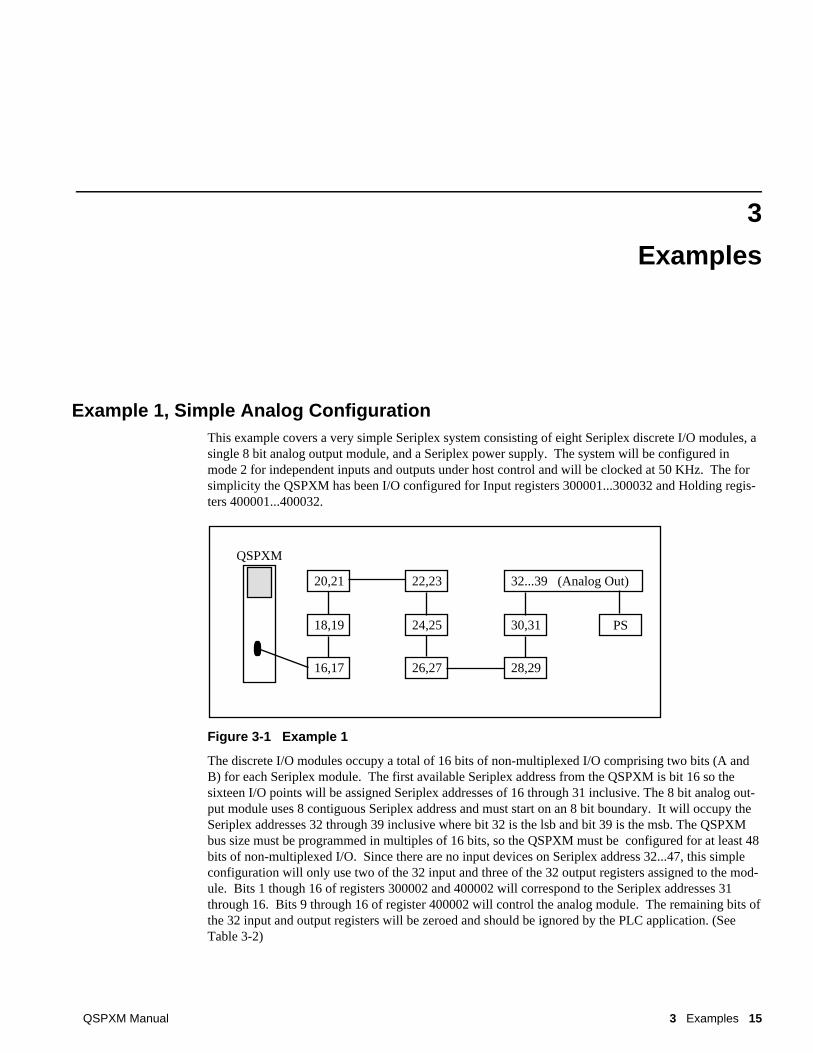
Example 1, Simple Analog ConfigurationThis example covers a very simple Seriplex system consisting of eight Seriplex discrete I/O modules, asingle 8 bit analog output module, and a Seriplex power supply. The system will be configured inmode 2 for independent inputs and outputs under host control and will be clocked at 50 KHz. The forsimplicity the QSPXM has been I/O configured for Input registers 300001...300032 and Holding regis-ters 400001...400032.
Figure 3-1 Example 1
The discrete I/O modules occupy a total of 16 bits of non-multiplexed I/O comprising two bits (A andB) for each Seriplex module. The first available Seriplex address from the QSPXM is bit 16 so thesixteen I/O points will be assigned Seriplex addresses of 16 through 31 inclusive. The 8 bit analog out-put module uses 8 contiguous Seriplex address and must start on an 8 bit boundary. It will occupy theSeriplex addresses 32 through 39 inclusive where bit 32 is the lsb and bit 39 is the msb. The QSPXMbus size must be programmed in multiples of 16 bits, so the QSPXM must be configured for at least 48bits of non-multiplexed I/O. Since there are no input devices on Seriplex address 32...47, this simpleconfiguration will only use two of the 32 input and three of the 32 output registers assigned to the mod-ule. Bits 1 though 16 of registers 300002 and 400002 will correspond to the Seriplex addresses 31through 16. Bits 9 through 16 of register 400002 will control the analog module. The remaining bits ofthe 32 input and output registers will be zeroed and should be ignored by the PLC application. (SeeTable 3-2)
QSPXM
16,17
18,19
20,21
26,27
24,25
22,23
28,29
30,31
32...39 (Analog Out)
PS
16 Examples 3 QSPXM Manual
The Configuration register 400001 should be set to the value 33282 (decimal) = 8202 (hex) =1000001000000010 (binary). This will place the network in RUN at 50KHz with a size of 48 bits. Ta-ble 3-1 displays the bit values for the Configuration register 400001.
Table 3-2 Example 1 Register List
The QSPXM has been assigned as an analog module so the ladder program will likely be written to usethe NOBT, NCBT, NBIT, SBIT, and RBIT instructions for direct bit manipulations of the analog regis-ters. The BLKM and other transfer blocks may also be used to move the analog values into discretelocations to simplify the ladder code. Example 2 shows this same system as a discrete configuration.
Figure 3-2 shows a simple ladder segment that uses the 16 bit ADD block to hard-code the configura-tion register, copies Seriplex input bit #17 to Seriplex output bit #28, and copies the analog input regis-ter 300115 to the Seriplex analog output module.
Figure 3-2 Example 1 Ladder Code
Table 3-1 Example 1 4x Configuration Register
01 (48 Bits)00000001 (50KHz)000001 (RUN)
1 2 3 4 5 6 7 8 9 10 11 12 13 14 15 16
Input Register HoldingRegister
1msb
2 3 4 5 6 7 8 9 10 11 12 13 14 15 16lsb
300001 400001 Status register and Configuration Register
Example 2, Simple Discrete ConfigurationThis example covers a Seriplex system of consisting of 21 Seriplex discrete I/O modules and a Seriplexpower supply. The system will be configured in mode 2 for independent inputs and outputs under hostcontrol and will be clocked at 50 KHz. The QSPXM will be configured as a discrete module with theinputs at 100001...100512 and the outputs at 000001...000512 and the Bit 3 of the Control Word will beset for discrete bit alignment.
Figure 3-3 Example 2
The discrete I/O modules occupy a total of 42 bits of non-multiplexed I/O comprising two bits (A andB) for each Seriplex module. The first available Seriplex address from the QSPXM is bit 16 so the 42I/O points will be assigned Seriplex address of 16 through 57 inclusive. The QSPXM bus size must beprogrammed in multiples of 16 bits, so the QSPXM must be configured for at least 64 bits of non-multiplexed I/O. The first 16 bits will be the configuration and status for the QSPXM. The next six-teen bits will be for Seriplex addresses 17..32 while the following 16 bits will be for Seriplex addresses33...48, followed by bits 49...64. The remaining bits of the 512 inputs and outputs will be zeroed andshould be ignored by the PLC application. (See Table 3-2)
Notice that Seriplex bit 16 is not available and that the Modicon byte boundaries are not aligned withthe Seriplex byte boundaries because the Modicon addresses start at 1 and the Seriplex address starts at0.
The Configuration bits 1010001000000011 (binary). This will place the network in RUN at 50KHzwith a size of 64 bits. Table 3-1 displays the bit values for the Configuration.
QSPXM
17,18
19,20
21,22
27,28
25,26
23,24
39,40
37,38
33,34
31,32
29,30
45,46
43,44
41,42
57,58
55,56
53,54
35,36
51,52
49,50
47,48
PS
18 Examples 3 QSPXM Manual
Table 3-4 Example 2 Bit List
Figure 3-4 shows a simple ladder segment that uses the 16 bit ADD block to hard-code the configura-tion register, copies Seriplex input bit #31 to Seriplex output bit #20.
Figure 3-4 Example 2 Ladder Code
Example 3, Multiplexed SystemSystems implementing Multiplexed Seriplex modules are configured much like the non-multiplexedsystems. The non-multiplexed bits start at Seriplex bit 16 and go up while the multiplexed words startat the end of the network and towards the beginning
For this example there are 8 multiplexed temperature sensors with four channels per device. Sincethere are four analog values per device, the Mux depth should be set to 4 (bit 6 ON and bit 5 OFF in the
configuration register). The Mux Width should be set to 8 words since there are 8 devices (bit 12 OFF,bit 11 OFF, bit 10 OFF, and bit 9 ON in the configuration register). There are also 6 discrete non-multiplexed devices on the network (12 bits).
The discrete non-multiplexed devices need 12 bits and may be placed in Seriplex addresses 16 through27 inclusive. The 8 sixteen bit words of multiplexing account for 128 bits of the Seriplex bus and muststart on a 16 bit boundary. Therefore the multiplexing may start at Seriplex bit 32 and continue throughbits 160. The bus length will be set for 160 bits (bit 16 ON, bit 15 OFF, bit 14 OFF, and bit 13 ON).
This system will be configured for Mode 2 (bit 4 OFF) and for RUN (bit 1 ON). The network speedonly needs to be 16kHz (bit 8 OFF, bit 7 OFF).
Figure 3-5 Example 3
The resulting value for the Configuration register is 33929 (decimal) = 8489 (hex) =1000010010001001 (binary). The QSPXM is assigned as analog registers by the PLC. The tables be-low describe the register format for the inputs and outputs at the PLC where QSPXM has been assignedaddresses 300001...300032 and 400001...400032.
Notice that the Seriplex setup is larger than the 32 registers available to the PLC. This means thatChannels 2 and 3 of the module with Seriplex addresses 144...159 will not be accessed by the PLC. Their inputs will be ignored by the QSPXM and their outputs will be set to zero.
1 No Internal Connection. May be used for Seriplex Shield Bare
2,6 Seriplex Common Black
3,7 Seriplex power, +12 or +24VDC Red
4,8 Seriplex clock Green or Blue
5,9 Seriplex data White
543
21
98
76
QSPXM Manual 5 Trouble Shooting 25
5
Trouble Shooting
V OK offWhen the voltage on the Seriplex network falls below the minimum working range, the green V OKlight goes off. Undervoltages may occur due to a cable break between the QSPXM and the Seriplexpower module, a loss of power to the power module, a cable short somewhere on the network, or afaulty power module. A DC voltage meter is a handy tool for tracing power problems.
After the undervoltage problem is solved, the QSPXM will automatically restart the Seriplex bus aslong as a good configuration is in Holding register 1 and the PLC is in RUN.
When the V OK light is off, the RUN light on the QSPXM will be off. The Seriplex network will notrun while a fault condition exists within the QSPXM. All Seriplex devices will revert to their pro-grammed default state.
FaultIn addition to the Undervoltage condition, the QSPXM can detect the following:
• Clock shorted low
• Clock shorted high
• Data shorted low
• Data shorted high
• Clock shorted to Data
• External clock active on the network
• Excess Data Line Capacitance for a given clock rate
• Running Mode 1 devices with a Mode 2 Host may sometimes generate a Fault. Especially at ahigh clock rate (100kHz).
If any of these situations occur, the red Fault light will be lit, the appropriate error bit will be set in thefirst input register assigned to the QSPXM, and the Seriplex network will stop. When the Fault light ison, the RUN light on the QSPXM will be off. The Seriplex network will not run while a fault conditionexists within the QSPXM. All Seriplex devices will revert to their programmed default state.
QSPXM Manual A NR&D Internet 27
Appendix A
NR&D Internet
Niobrara is on the World Wide Web! Visit our home page athttp://www.niobrara.com to see product information, cutsheets, application notes,and ftp current software releases.
Additional information about Seriplex may be found at www.seriplex.org.
Additional information about the Quantum may be found at www.modicon.com.
QSPXM Manual B Modsoft Traffic Cop Configuration 29
Appendix B
Modsoft Traffic Cop Configuration
The register configuration of the QSPXM is governed by its entry in the Traffic Cop description andcharacteristic file: GCNFTCOP.SYS. This file is typically located in the \MODSOFT\RUNTIME di-rectory.
NOTE: Pay special notice to the warning about editing this file with editorsthat do not support line width greater than 255 characters.DO NOT use MS-DOS EDIT on this file!
The entry for the QSPXM follows the form of a Quantum Dual Port Memory I/O module with 64 bytesof input and 64 bytes of output. The standard entry used in Modsoft V2.4 is shown below:
The first 10 characters are the Name of the module.
The 214 is the next entry in the list of available devices. If you are adding this line, choose the nextfree number in the list.
The 0 in character position 16 indicates that other modules may be inserted in this drop.
The 64 in character positions 18 and 19 set the number of INPUT bytes.
The 64 in character positions 21 and 22 set the number of OUTPUT bytes.
The next field is the text description (19 characters max.).
The 0 in position 40 determines that the module is a discrete module and may take 0x, 1x, 3x, 4xreferences.
The module ID is L012F.
The 2 that follows signifies that the QSPXM is a QUANTUM DPM module.
The last 0000 tells the T_MODULE.LmsSlotData.a to use the default module bits.
It is possible to modify the width of the INPUT bytes and OUTPUT bytes to adjust the QSPXM for aunique application. For instance, in Examples 1 and 2, the Seriplex network is small and only 3 words(6 bytes) of I/O was actually used of the 32 words (64 bytes) assigned. The Quantum rack only allows64 words total for the rack so it may be desirable to reduce the number used by the QSPXM to allow for
30 Modsoft Traffic Cop Configuration B QSPXM Manual
other I/O. In Examples 1 and 2, the Input and Output bytes might be set down to 10 bytes each to allowfor some future expansion of the Seriplex network and still free some I/O for other devices.
NOTE: If the entry in the Traffic Cop configuration file is altered, all QSPXMs in the PLC system willuse this entry. Also, special care will be needed during future updates of Modsoft to carry the alteredsetting to the new revision.
QSPXM Manual C Concept 2.1 Configuration 31
Appendix C
Concept 2.1 Configuration
The register configuration of the QSPXM is governed by its entry in the Traffic Cop description andcharacteristic file: GCNFTCOP.SYS. This file is typically located in the \MODSOFT\RUNTIME di-rectory.