276
Modicon Micro PLCs TSX 3705/3708/3710/3720 Implementation Manual Volume 3 TSX DM 37 xx eng

Modicon Micro PLCsTSX 3705/3708/3710/3720Implementation Manual Volume 3TSX DM 37 xx eng

2
Document Set
Document Set
At a Glance This manual comprises three volumes. Volume 1
Processors, Implementation/troubleshooting/maintenance, Process supplies and AS-i.
Volume 2 Discrete input/output modules, Discrete I/O remote module.
Volume 3 Analog, Counting built into the bases, Position measurement, Communication built into the bases, Analog input/output modules, Counting module, Communication by PCMCIA card.
TSX DM 37 xx 3

Document Set
4 TSX DM 37 xx
Table of Contents
About the Book . . . . . . . . . . . . . . . . . . . . . . . . . . . . . . . . . . . . . .11
Part I The analog input/output . . . . . . . . . . . . . . . . . . . . . . . . . 13At a Glance . . . . . . . . . . . . . . . . . . . . . . . . . . . . . . . . . . . . . . . . . . . . . . . . . . . . . 13
Chapter 1 General introduction to analog input/output modules . . . . . . 15At a Glance . . . . . . . . . . . . . . . . . . . . . . . . . . . . . . . . . . . . . . . . . . . . . . . . . . . . . 15General description of the analog modules. . . . . . . . . . . . . . . . . . . . . . . . . . . . . 16Physical description of analog modules . . . . . . . . . . . . . . . . . . . . . . . . . . . . . . . 17Input/output analog modules catalog . . . . . . . . . . . . . . . . . . . . . . . . . . . . . . . . . 18
Chapter 2 General rules for implementing the analog input/output modules . . . . . . . . . . . . . . . . . . . . . . . . . . . . . . . . . . . . . . . . . . . . 19At a Glance . . . . . . . . . . . . . . . . . . . . . . . . . . . . . . . . . . . . . . . . . . . . . . . . . . . . . 19Analog input/output module installation precautions. . . . . . . . . . . . . . . . . . . . . . 20labeling of analog input/output modules . . . . . . . . . . . . . . . . . . . . . . . . . . . . . . . 21Precautions and general rules concerning the wiring to the analog input/output modules. . . . . . . . . . . . . . . . . . . . . . . . . . . . . . . . . . . . . . . . . . . . . . . . . . . . . . . . 22
Chapter 3 The analog input modules TSX AEZ 801/802 . . . . . . . . . . . . . 27At a Glance . . . . . . . . . . . . . . . . . . . . . . . . . . . . . . . . . . . . . . . . . . . . . . . . . . . . . 27Introduction to TSX AEZ 801/802 modules. . . . . . . . . . . . . . . . . . . . . . . . . . . . . 28Input processing . . . . . . . . . . . . . . . . . . . . . . . . . . . . . . . . . . . . . . . . . . . . . . . . . 30Fault processing . . . . . . . . . . . . . . . . . . . . . . . . . . . . . . . . . . . . . . . . . . . . . . . . . 35Characteristics of TSX AEZ 801/802 analog modules . . . . . . . . . . . . . . . . . . . . 36Connections for TSX AEZ 801/802 analog modules. . . . . . . . . . . . . . . . . . . . . . 37
Chapter 4 The analog input module TSX AEZ 414 . . . . . . . . . . . . . . . . . . 39At a Glance . . . . . . . . . . . . . . . . . . . . . . . . . . . . . . . . . . . . . . . . . . . . . . . . . . . . . 39Introduction to the module TSX AEZ 414 . . . . . . . . . . . . . . . . . . . . . . . . . . . . . . 40Input processing . . . . . . . . . . . . . . . . . . . . . . . . . . . . . . . . . . . . . . . . . . . . . . . . . 42Fault processing . . . . . . . . . . . . . . . . . . . . . . . . . . . . . . . . . . . . . . . . . . . . . . . . . 48Features of the analog module TSX AEZ 414. . . . . . . . . . . . . . . . . . . . . . . . . . . 49Connections for the analog module TSX AEZ 414 . . . . . . . . . . . . . . . . . . . . . . . 52Cabling recommendations for thermoprobes Pt 100 and Ni1000 . . . . . . . . . . . . 55
5
Cabling and installation recommendations for thermocouples . . . . . . . . . . . . . . 56
Chapter 5 The analog output module TSX ASZ 401. . . . . . . . . . . . . . . . . 59At a Glance . . . . . . . . . . . . . . . . . . . . . . . . . . . . . . . . . . . . . . . . . . . . . . . . . . . . . 59Introduction to the TSX ASZ 401 module . . . . . . . . . . . . . . . . . . . . . . . . . . . . . . 60Output processing . . . . . . . . . . . . . . . . . . . . . . . . . . . . . . . . . . . . . . . . . . . . . . . . 61Fault processing. . . . . . . . . . . . . . . . . . . . . . . . . . . . . . . . . . . . . . . . . . . . . . . . . . 62Features of the analog module TSX ASZ 401 . . . . . . . . . . . . . . . . . . . . . . . . . . . 63Connections for the analog module TSX ASZ 401 . . . . . . . . . . . . . . . . . . . . . . . 64
Chapter 6 The analog output module TSX ASZ 200. . . . . . . . . . . . . . . . . 65At a Glance . . . . . . . . . . . . . . . . . . . . . . . . . . . . . . . . . . . . . . . . . . . . . . . . . . . . . 65Introduction to the module TSX ASZ 200 . . . . . . . . . . . . . . . . . . . . . . . . . . . . . . 66Output Processing . . . . . . . . . . . . . . . . . . . . . . . . . . . . . . . . . . . . . . . . . . . . . . . . 67Fault processing. . . . . . . . . . . . . . . . . . . . . . . . . . . . . . . . . . . . . . . . . . . . . . . . . . 68Features of the analog module TSX ASZ 200 . . . . . . . . . . . . . . . . . . . . . . . . . . . 69Connections for the analog module TSX ASZ 200 . . . . . . . . . . . . . . . . . . . . . . . 70
Chapter 7 TSX AMZ 600 Analog Input Modules . . . . . . . . . . . . . . . . . . . . 71At a Glance . . . . . . . . . . . . . . . . . . . . . . . . . . . . . . . . . . . . . . . . . . . . . . . . . . . . . 71Introduction to the TSX AMZ 600 Module . . . . . . . . . . . . . . . . . . . . . . . . . . . . . . 72Input Processing . . . . . . . . . . . . . . . . . . . . . . . . . . . . . . . . . . . . . . . . . . . . . . . . . 74Output Processing . . . . . . . . . . . . . . . . . . . . . . . . . . . . . . . . . . . . . . . . . . . . . . . . 80Characteristics of the TSX AMZ 600 Module. . . . . . . . . . . . . . . . . . . . . . . . . . . . 81Connecting the TSX AMZ 600 Analog Module . . . . . . . . . . . . . . . . . . . . . . . . . . 83
Part II Counter modules . . . . . . . . . . . . . . . . . . . . . . . . . . . . . . . .85At a Glance . . . . . . . . . . . . . . . . . . . . . . . . . . . . . . . . . . . . . . . . . . . . . . . . . . . . . 85
Chapter 8 Counter modules: Introduction . . . . . . . . . . . . . . . . . . . . . . . . 87At a Glance . . . . . . . . . . . . . . . . . . . . . . . . . . . . . . . . . . . . . . . . . . . . . . . . . . . . . 87Counter modules: General. . . . . . . . . . . . . . . . . . . . . . . . . . . . . . . . . . . . . . . . . . 88Physical description . . . . . . . . . . . . . . . . . . . . . . . . . . . . . . . . . . . . . . . . . . . . . . . 90Installation and assembly of the TSX CTZ 1A/2A/2AA modules . . . . . . . . . . . . . 91
Chapter 9 Counter modules: Standard functions . . . . . . . . . . . . . . . . . . 93At a Glance . . . . . . . . . . . . . . . . . . . . . . . . . . . . . . . . . . . . . . . . . . . . . . . . . . . . . 93Down-counter function. . . . . . . . . . . . . . . . . . . . . . . . . . . . . . . . . . . . . . . . . . . . . 94Up-counting function . . . . . . . . . . . . . . . . . . . . . . . . . . . . . . . . . . . . . . . . . . . . . . 95Up/down counting function. . . . . . . . . . . . . . . . . . . . . . . . . . . . . . . . . . . . . . . . . . 96Up/down counting on TSX CTZ 1A/2A/2AA modules . . . . . . . . . . . . . . . . . . . . . 97Principle Diagram. . . . . . . . . . . . . . . . . . . . . . . . . . . . . . . . . . . . . . . . . . . . . . . . . 99Up/down counting on TSX CTZ 1A/2A/2AA modules . . . . . . . . . . . . . . . . . . . . 100Provisional diagram 1 . . . . . . . . . . . . . . . . . . . . . . . . . . . . . . . . . . . . . . . . . . . . 103Provisional diagram 2 . . . . . . . . . . . . . . . . . . . . . . . . . . . . . . . . . . . . . . . . . . . . 104Provisional diagram 3 . . . . . . . . . . . . . . . . . . . . . . . . . . . . . . . . . . . . . . . . . . . . 105
6
Provisional diagram 4 . . . . . . . . . . . . . . . . . . . . . . . . . . . . . . . . . . . . . . . . . . . . 106How the EPSR is connected . . . . . . . . . . . . . . . . . . . . . . . . . . . . . . . . . . . . . . . 107
Chapter 10 Implementing up counting. . . . . . . . . . . . . . . . . . . . . . . . . . . . 109At a Glance . . . . . . . . . . . . . . . . . . . . . . . . . . . . . . . . . . . . . . . . . . . . . . . . . . . . 109Number of channels managed by the TSX 37 PLC . . . . . . . . . . . . . . . . . . . . . 110Sensor and encoder types used . . . . . . . . . . . . . . . . . . . . . . . . . . . . . . . . . . . . 112General features of the TSX CTZ 1A/2A/2AA modules . . . . . . . . . . . . . . . . . . 113Counting input features . . . . . . . . . . . . . . . . . . . . . . . . . . . . . . . . . . . . . . . . . . . 114Auxiliary input features . . . . . . . . . . . . . . . . . . . . . . . . . . . . . . . . . . . . . . . . . . . 116Pin configuration in the high density point SUB D 15 connectors . . . . . . . . . . . 117Pin configuration of a 20-pin HE10 type connector . . . . . . . . . . . . . . . . . . . . . . 119Principle of connection for encoder type counting sensors . . . . . . . . . . . . . . . . 121Example of module/encoder connection with RS 422 line transmitter outputs . 123Example of PLC/encoder with Totem Pole Outputs . . . . . . . . . . . . . . . . . . . . . 124Example of PLC/encoder connection with NPN open collector outputs . . . . . . 126Example of PLC/encoder connection with PNP open collector outputs . . . . . . 127Connection of supply and sensors on auxiliary inputs . . . . . . . . . . . . . . . . . . . 128Maximum phase shifting between inputs IA and IB. . . . . . . . . . . . . . . . . . . . . . 129Connection principle for DDP type counting sensors . . . . . . . . . . . . . . . . . . . . 130Connection of counting sensors and their supply . . . . . . . . . . . . . . . . . . . . . . . 132Connection of sensors on auxiliary inputs and their supply . . . . . . . . . . . . . . . 133General rules for implementation . . . . . . . . . . . . . . . . . . . . . . . . . . . . . . . . . . . 134
Chapter 11 TELEFAST 2 connection base: ABE-7CPA01 . . . . . . . . . . . . 137At a Glance . . . . . . . . . . . . . . . . . . . . . . . . . . . . . . . . . . . . . . . . . . . . . . . . . . . . 137Introduction . . . . . . . . . . . . . . . . . . . . . . . . . . . . . . . . . . . . . . . . . . . . . . . . . . . . 138Cabling layout . . . . . . . . . . . . . . . . . . . . . . . . . . . . . . . . . . . . . . . . . . . . . . . . . . 139Construction and mounting . . . . . . . . . . . . . . . . . . . . . . . . . . . . . . . . . . . . . . . . 140Availability of the counting signals on the TELEFAST screw terminal block. . . 141Matching TELEFAST terminal blocks and 15-pin SUB-D connector. . . . . . . . . 142
Chapter 12 TELEFAST 2 connection base: ABE-7H08R10/7H16R20 . . . 145At a Glance . . . . . . . . . . . . . . . . . . . . . . . . . . . . . . . . . . . . . . . . . . . . . . . . . . . . 145At a Glance . . . . . . . . . . . . . . . . . . . . . . . . . . . . . . . . . . . . . . . . . . . . . . . . . . . . 146Availability of the signals on the TELEFAST screw terminal block . . . . . . . . . . 147Correspondences between TELEFAST terminal blocks and HE10 connector . 148
Chapter 13 Wiring accessories for incremental encoder: TSX TAP S15•• . . . . . . . . . . . . . . . . . . . . . . . . . . . . . . . . . . . . . . . . . . . . . . . . . .151At a Glance . . . . . . . . . . . . . . . . . . . . . . . . . . . . . . . . . . . . . . . . . . . . . . . . . . . . 151Description . . . . . . . . . . . . . . . . . . . . . . . . . . . . . . . . . . . . . . . . . . . . . . . . . . . . 152Mounting and measurements of the TSX TAP S15 05/24 . . . . . . . . . . . . . . . . 153Connecting an encoder with a TSX TAP S15 05 accessory . . . . . . . . . . . . . . . 155Connecting an encoder with a TSX TAP S15 24 accessory . . . . . . . . . . . . . . . 156Connection to modules with HE10 connectors . . . . . . . . . . . . . . . . . . . . . . . . . 157
7
Part III TSX CTZ 1B Position Measurement Module . . . . . . . . . 159At a Glance . . . . . . . . . . . . . . . . . . . . . . . . . . . . . . . . . . . . . . . . . . . . . . . . . . . . 159
Chapter 14 Introduction to the CTZ 1B Measurement Module . . . . . . . . 161At a Glance . . . . . . . . . . . . . . . . . . . . . . . . . . . . . . . . . . . . . . . . . . . . . . . . . . . . 161General Information on the Measurement Module . . . . . . . . . . . . . . . . . . . . . . 162Physical Description of the Module . . . . . . . . . . . . . . . . . . . . . . . . . . . . . . . . . . 163Number of Channels Managed by a TSX 37 . . . . . . . . . . . . . . . . . . . . . . . . . . . 164Installation and Assembly of TSX CTZ 1B Modules . . . . . . . . . . . . . . . . . . . . . 165
Chapter 15 Characteristics of the Apparatus Used . . . . . . . . . . . . . . . . . 167At a Glance . . . . . . . . . . . . . . . . . . . . . . . . . . . . . . . . . . . . . . . . . . . . . . . . . . . . 167Encoder Selection . . . . . . . . . . . . . . . . . . . . . . . . . . . . . . . . . . . . . . . . . . . . . . . 168Selection and Protection of the Encoder Power Supply . . . . . . . . . . . . . . . . . . 170General Characteristics of the TSX CTZ 1B Module . . . . . . . . . . . . . . . . . . . . . 171Capture Input Characteristics . . . . . . . . . . . . . . . . . . . . . . . . . . . . . . . . . . . . . . 172
Chapter 16 Implementation Measurement Module. . . . . . . . . . . . . . . . . . 173At a Glance . . . . . . . . . . . . . . . . . . . . . . . . . . . . . . . . . . . . . . . . . . . . . . . . . . . . 173Installation Precautions . . . . . . . . . . . . . . . . . . . . . . . . . . . . . . . . . . . . . . . . . . . 174Wiring Precautions. . . . . . . . . . . . . . . . . . . . . . . . . . . . . . . . . . . . . . . . . . . . . . . 175Link between an Encoder and the TSX CTZ 1B Module . . . . . . . . . . . . . . . . . . 176Linking the Encoder Supply and Capture Inputs . . . . . . . . . . . . . . . . . . . . . . . . 179
Chapter 17 TELEFAST ABE-7CPA01 Connection Base. . . . . . . . . . . . . . 181At a Glance . . . . . . . . . . . . . . . . . . . . . . . . . . . . . . . . . . . . . . . . . . . . . . . . . . . . 181Connecting TELEFAST 2: ABE-7CPA01. . . . . . . . . . . . . . . . . . . . . . . . . . . . . . 182Connection diagram for the TELEFAST ABE-7CPA01 . . . . . . . . . . . . . . . . . . . 184Description of the Screw Terminal Blocks for the TELEFAST ABE-7CPA01 . . 186
Chapter 18 TELEFAST ABE-7CPA11 Connection Base. . . . . . . . . . . . . . 189At a Glance . . . . . . . . . . . . . . . . . . . . . . . . . . . . . . . . . . . . . . . . . . . . . . . . . . . . 189TELEFAST 2 Connection and Adaptation Base: ABE-7CPA11 . . . . . . . . . . . . 190Connecting the TELEFAST ABE-7CPA11 to the TSX CTZ 1B Module. . . . . . . 192Physical Description of the TELEFAST 2: ABE-7CPA11. . . . . . . . . . . . . . . . . . 193TELEFAST 2 Connection Base Characteristics: ABE-7CPA11. . . . . . . . . . . . . 194Connecting the TELEFAST 2 Base: ABE-7CPA11 . . . . . . . . . . . . . . . . . . . . . . 197Connecting Encoders Supplied with 10...30 V. . . . . . . . . . . . . . . . . . . . . . . . . . 199Connecting Encoders Supplied with 5 V . . . . . . . . . . . . . . . . . . . . . . . . . . . . . . 201Example of Multiplexing of Encoders Supplied with 5V. . . . . . . . . . . . . . . . . . . 203Example of a connection: an encoder connected by a TELEFAST to the TSX CTZ 1B ENC connector . . . . . . . . . . . . . . . . . . . . . . . . . . . . . . . . . . . . . . . . . . . . . . . 204Example of a connection: 4 encoders connected by 2 TELEFASTs to the TSX CTZ 1B ENC connector . . . . . . . . . . . . . . . . . . . . . . . . . . . . . . . . . . . . . . . . . . . . . . . 205Example of a connection: 4 encoders connected by 3 TELEFASTs to the TSX CTZ 1B ENC connector . . . . . . . . . . . . . . . . . . . . . . . . . . . . . . . . . . . . . . . . . . . . . . . 208
8
Example of a connection: 4 encoders connected by 4 TELEFASTs to the TSX CTZ 1B ENC connector. . . . . . . . . . . . . . . . . . . . . . . . . . . . . . . . . . . . . . . . . . . . . . . 210Wiring Rules and Precautions. . . . . . . . . . . . . . . . . . . . . . . . . . . . . . . . . . . . . . 212Configuration of the TELEFAST Connection Base . . . . . . . . . . . . . . . . . . . . . . 215
Part IV Communication via a PCMCIA Card. . . . . . . . . . . . . . . 217At a Glance . . . . . . . . . . . . . . . . . . . . . . . . . . . . . . . . . . . . . . . . . . . . . . . . . . . . 217
Chapter 19 Introduction to PCMCIA Cards . . . . . . . . . . . . . . . . . . . . . . . . 219At a Glance . . . . . . . . . . . . . . . . . . . . . . . . . . . . . . . . . . . . . . . . . . . . . . . . . . . . 219 Introduction to PCMCIA Cards. . . . . . . . . . . . . . . . . . . . . . . . . . . . . . . . . . . . . 220Description of PCMCIA cards . . . . . . . . . . . . . . . . . . . . . . . . . . . . . . . . . . . . . . 223Physical features. . . . . . . . . . . . . . . . . . . . . . . . . . . . . . . . . . . . . . . . . . . . . . . . 224Operational standard. . . . . . . . . . . . . . . . . . . . . . . . . . . . . . . . . . . . . . . . . . . . . 225Compatibility . . . . . . . . . . . . . . . . . . . . . . . . . . . . . . . . . . . . . . . . . . . . . . . . . . . 226
Chapter 20 Implementation of PCMCIA cards . . . . . . . . . . . . . . . . . . . . . . 227At a Glance . . . . . . . . . . . . . . . . . . . . . . . . . . . . . . . . . . . . . . . . . . . . . . . . . . . . 227Installing cards and cords for the TSX 37-2•. . . . . . . . . . . . . . . . . . . . . . . . . . . 228PCMCIA card references . . . . . . . . . . . . . . . . . . . . . . . . . . . . . . . . . . . . . . . . . 229PCMCIA card operational display . . . . . . . . . . . . . . . . . . . . . . . . . . . . . . . . . . . 230Visual diagnostics of the PCMCIA card. . . . . . . . . . . . . . . . . . . . . . . . . . . . . . . 231
Chapter 21 Connecting the PCMCIA cards . . . . . . . . . . . . . . . . . . . . . . . . 235At a Glance . . . . . . . . . . . . . . . . . . . . . . . . . . . . . . . . . . . . . . . . . . . . . . . . . . . . 235Connecting the TSX SCP 111 card. . . . . . . . . . . . . . . . . . . . . . . . . . . . . . . . . . 236Connecting the TSX SCP 112 card. . . . . . . . . . . . . . . . . . . . . . . . . . . . . . . . . . 238Point-to-point connection. . . . . . . . . . . . . . . . . . . . . . . . . . . . . . . . . . . . . . . . . . 239Multipoint connection. . . . . . . . . . . . . . . . . . . . . . . . . . . . . . . . . . . . . . . . . . . . . 240Dynamic performances . . . . . . . . . . . . . . . . . . . . . . . . . . . . . . . . . . . . . . . . . . . 241Connecting the TSX SCP 112 to April 5000/7000 PLCs. . . . . . . . . . . . . . . . . . 243Multidrop type link for the TSX SCP 112 cards. . . . . . . . . . . . . . . . . . . . . . . . . 245Connecting the TSX SCP 114 card to the UNITELWAY network . . . . . . . . . . . 249Connecting the TSX SCP 114 card to the Modbus/JBus . . . . . . . . . . . . . . . . . 251RS 422, multi-protocol asynchronous link connection. . . . . . . . . . . . . . . . . . . . 254Connecting TSX FPP 20 cards . . . . . . . . . . . . . . . . . . . . . . . . . . . . . . . . . . . . . 255Connecting TSX FPP 10 card . . . . . . . . . . . . . . . . . . . . . . . . . . . . . . . . . . . . . . 256Connecting TSX MBP 100 card . . . . . . . . . . . . . . . . . . . . . . . . . . . . . . . . . . . . 257Connecting the TSX MBP CE 030/060 cable on the Modicon 990 NAD 230 00 connection device side . . . . . . . . . . . . . . . . . . . . . . . . . . . . . . . . . . . . . . . . . . . 259Summary of the link cables . . . . . . . . . . . . . . . . . . . . . . . . . . . . . . . . . . . . . . . . 261Safety measures for connecting PCMCIA cards. . . . . . . . . . . . . . . . . . . . . . . . 263PCMCIA card consumption. . . . . . . . . . . . . . . . . . . . . . . . . . . . . . . . . . . . . . . . 264
Chapter 22 Communication via a Modem PCMCIA card . . . . . . . . . . . . . 265At a Glance . . . . . . . . . . . . . . . . . . . . . . . . . . . . . . . . . . . . . . . . . . . . . . . . . . . . 265
9
At a Glance . . . . . . . . . . . . . . . . . . . . . . . . . . . . . . . . . . . . . . . . . . . . . . . . . . . . 266Description. . . . . . . . . . . . . . . . . . . . . . . . . . . . . . . . . . . . . . . . . . . . . . . . . . . . . 267Installing the TSX MDM 10 card . . . . . . . . . . . . . . . . . . . . . . . . . . . . . . . . . . . . 268Connecting to the telephone network . . . . . . . . . . . . . . . . . . . . . . . . . . . . . . . . 269Connecting the adapters . . . . . . . . . . . . . . . . . . . . . . . . . . . . . . . . . . . . . . . . . . 271Electrical features and technical specifications . . . . . . . . . . . . . . . . . . . . . . . . . 272
Index . . . . . . . . . . . . . . . . . . . . . . . . . . . . . . . . . . . . . . . . . . . . . . 273
10
About the Book
At a Glance
Document Scope This manual describes the various standard functions of the Micro.It includes 6 parts: 1 Analog built in to bases, 2 Counter built into bases, 3 Communication built into the bases, 4 Analog input/output modules, 5 Counting modules, 6 Communication by PCMCIA cards.
User Comments We welcome your comments about this document. You can reach us by e-mail at [email protected]
TSX DM 37 xx 11

About the Book
12 TSX DM 37 xx
TSX DM 37 xx
I
The analog input/outputAt a Glance
Aim of this tab This part introduces the range of analog input/output modules on offer TSX 37.
What's in this Part?
This part contains the following chapters:
Chapter Chapter Name Page
1 General introduction to analog input/output modules 15
2 General rules for implementing the analog input/output modules
19
3 The analog input modules TSX AEZ 801/802 27
4 The analog input module TSX AEZ 414 39
5 The analog output module TSX ASZ 401 59
6 The analog output module TSX ASZ 200 65
7 TSX AMZ 600 Analog Input Modules 71
13

Analog modules
14 TSX DM 37 xx
TSX DM 37 xx
1
General introduction to analog input/output modulesAt a Glance
Aim of this chapter
This chapter gives an outline of the analog input/output modules.
What's in this Chapter?
This chapter contains the following topics:
Topic Page
General description of the analog modules 16
Physical description of analog modules 17
Input/output analog modules catalog 18
15
Introduction to analog modules
General description of the analog modules
At a Glance The analog input/output modules in the Micro range are half-format modules equipped with a screw terminal block.they can be positioned in all the available positions of the PLCs TSX 37-05/08/10 et TSX 37-21/22, except the first position in the base.
Description The maximum number of analog modules it is possible to use in a Micro configuration is : 2 modules for a TSX 37-05/08/10 configuration, positioned either in the base or
in the extension ; 4 modules for a TSX 37-21/22 configuration, positioned either in the base or in
the extension, but with the following limitation ; a maximum of 2 modules TSX ASZ 200 can be positioned in the base because of their power usage.
Note: When the internal cold junction compensation is used it is advisable to position the modules TSX AEZ 414 in the positions situated in the low part of the PLC (base or extension).
Note: When an analog module is positioned in the mini extension rack of a PLC that is supplied alternatively, this mini rack should be supplied with 24 VDC.
16 TSX DM 37 xx
Introduction to analog modules
Physical description of analog modules
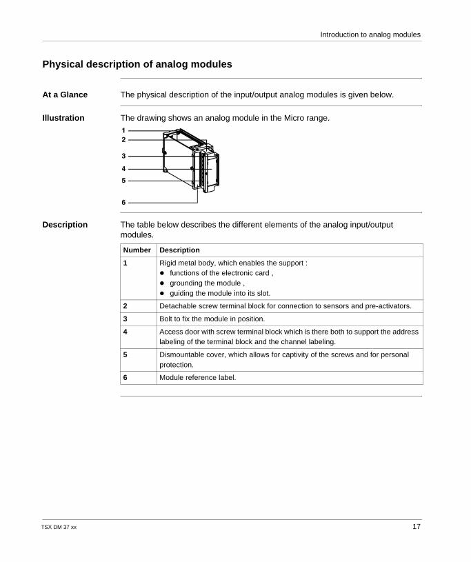
At a Glance The physical description of the input/output analog modules is given below.
Illustration The drawing shows an analog module in the Micro range.
Description The table below describes the different elements of the analog input/output modules.
Number Description
1 Rigid metal body, which enables the support : functions of the electronic card , grounding the module , guiding the module into its slot.
2 Detachable screw terminal block for connection to sensors and pre-activators.
3 Bolt to fix the module in position.
4 Access door with screw terminal block which is there both to support the address labeling of the terminal block and the channel labeling.
5 Dismountable cover, which allows for captivity of the screws and for personal protection.
6 Module reference label.
TSX DM 37 xx 17
Introduction to analog modules
Input/output analog modules catalog
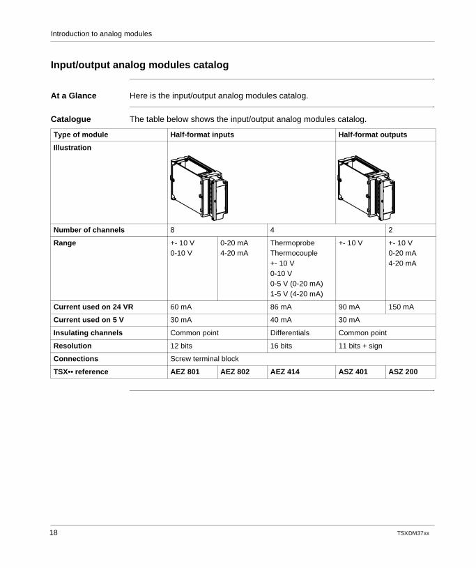
At a Glance Here is the input/output analog modules catalog.
Catalogue The table below shows the input/output analog modules catalog.
Type of module Half-format inputs Half-format outputs
Illustration
Number of channels 8 4 2
Range +- 10 V0-10 V
0-20 mA4-20 mA
ThermoprobeThermocouple+- 10 V0-10 V0-5 V (0-20 mA)1-5 V (4-20 mA)
+- 10 V +- 10 V0-20 mA4-20 mA
Current used on 24 VR 60 mA 86 mA 90 mA 150 mA
Current used on 5 V 30 mA 40 mA 30 mA
Insulating channels Common point Differentials Common point
Resolution 12 bits 16 bits 11 bits + sign
Connections Screw terminal block
TSX•• reference AEZ 801 AEZ 802 AEZ 414 ASZ 401 ASZ 200
18 TSX DM 37 xx
TSX DM 37 xx
2
General rules for implementing the analog input/output modulesAt a Glance
Aim of this chapter
This chapter presents the general rules for implementing analog input/output modules.
What's in this Chapter?
This chapter contains the following topics:
Topic Page
Analog input/output module installation precautions 20
labeling of analog input/output modules 21
Precautions and general rules concerning the wiring to the analog input/output modules
22
19
Implementing the analog modules
Analog input/output module installation precautions
At a Glance The precautions taken when putting the modules and terminals into place are given in detail below.
Precautions
WARNING
Risk of modules deteriorating
The modules should always be assembled and dismounted when the PLC is turned off.
Failure to follow this precaution can result in death, serious injury, or equipment damage.
WARNING
Protection of the slots not used by a module
The empty positions (not occupied by a module) must be protected by a cover, which is sold in a set under the reference TSX RKA 01.
Failure to follow this precaution can result in death, serious injury, or equipment damage.
20 TSX DM 37 xx
Implementing the analog modules
labeling of analog input/output modules
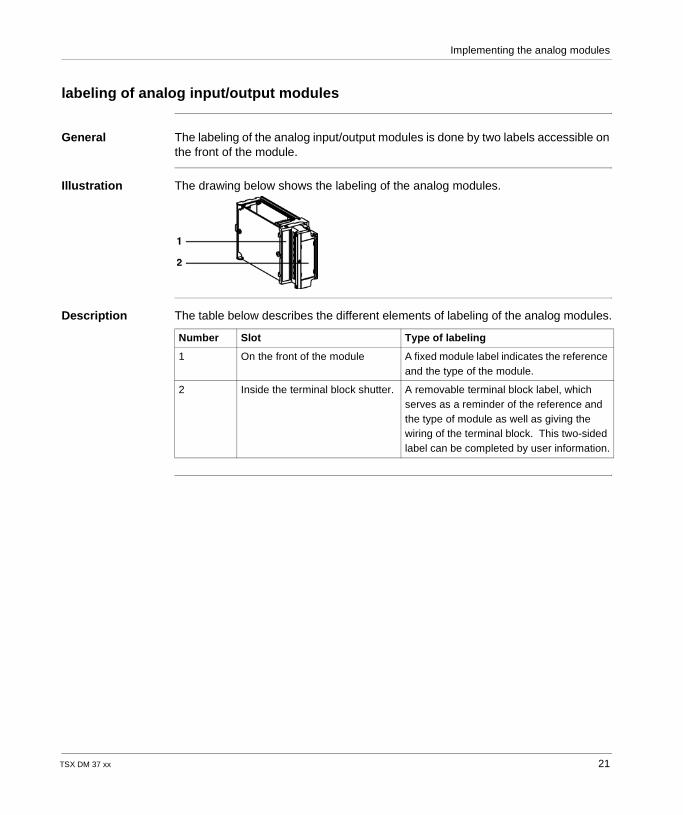
General The labeling of the analog input/output modules is done by two labels accessible on the front of the module.
Illustration The drawing below shows the labeling of the analog modules.
Description The table below describes the different elements of labeling of the analog modules.
Number Slot Type of labeling
1 On the front of the module A fixed module label indicates the reference and the type of the module.
2 Inside the terminal block shutter. A removable terminal block label, which serves as a reminder of the reference and the type of module as well as giving the wiring of the terminal block. This two-sided label can be completed by user information.
TSX DM 37 xx 21
Implementing the analog modules
Precautions and general rules concerning the wiring to the analog input/output modules
General In order to protect the signal in relation to the exterior noises in series mode and noises in common mode, it is advisable respect to the following precautions concerning the nature of the conductors, shielding of cables, the association of conductors in cables, routing of the cables, the reference to ground of the sensors and pre-sensors potential.
22 TSX DM 37 xx
Implementing the analog modules
Wiring precautions
WARNING
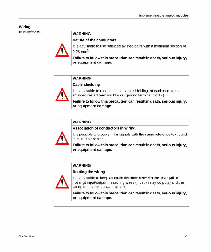
Nature of the conductors
It is advisable to use shielded twisted pairs with a minimum section of
0.28 mm2.
Failure to follow this precaution can result in death, serious injury, or equipment damage.
WARNING
Cable shielding
It is advisable to reconnect the cable shielding, at each end, to the shielded restart terminal blocks (ground terminal blocks).
Failure to follow this precaution can result in death, serious injury, or equipment damage.
WARNING
Association of conductors in wiring
It is possible to group similar signals with the same reference to ground in multi-pair cables.
Failure to follow this precaution can result in death, serious injury, or equipment damage.
WARNING
Routing the wiring
It is advisable to keep as much distance between the TOR (all or nothing) input/output measuring wires (mostly relay outputs) and the wiring that carries power signals.
Failure to follow this precaution can result in death, serious injury, or equipment damage.
TSX DM 37 xx 23
Implementing the analog modules
Sensors and pre-sensors
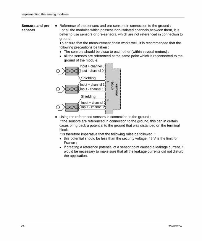
Reference of the sensors and pre-sensors in connection to the ground :For all the modules which possess non-isolated channels between them, it is better to use sensors or pre-sensors, which are not referenced in connection to ground.To ensure that the measurement chain works well, it is recommended that the following precautions be taken : The sensors should be close to each other (within several meters) ; all the sensors are referenced at the same point which is reconnected to the
ground of the module.
Using the referenced sensors in connection to the ground :If the sensors are referenced in connection to the ground, this can in certain cases bring back a potential to the ground that was distanced on the terminal block. It is therefore imperative that the following rules be followed : this potential should be less than the security voltage, 48 V is the limit for
France ; if creating a reference potential of a sensor point caused a leakage current, it
would be necessary to make sure that all the leakage currents did not disturb the application.
Input + channel 0Input - channel 0
Input + channel 1Input - channel 1
Input + channel 2Input - channel 2
Shielding
Shielding
Term
inalblock
24 TSX DM 37 xx
Implementing the analog modules
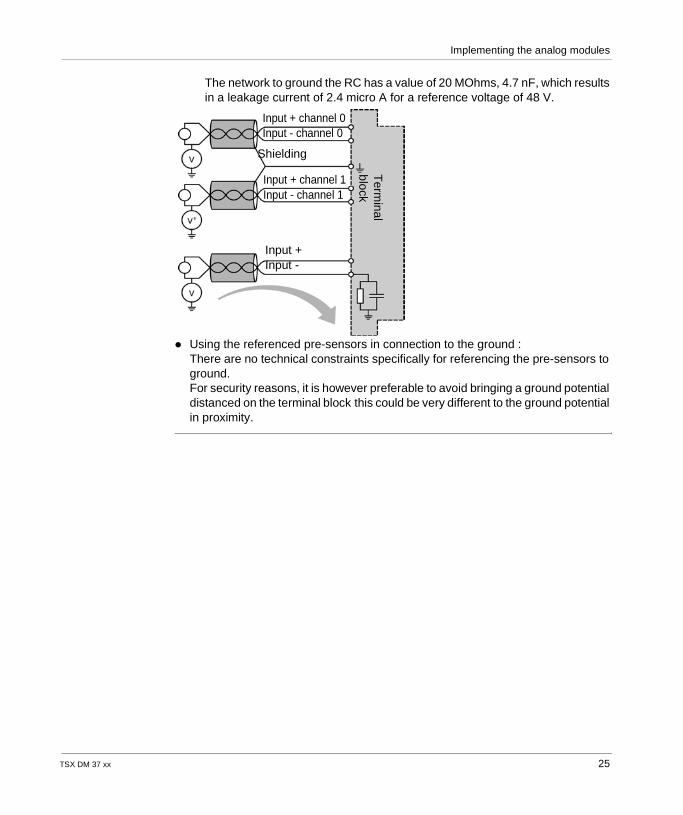
The network to ground the RC has a value of 20 MOhms, 4.7 nF, which results in a leakage current of 2.4 micro A for a reference voltage of 48 V.
Using the referenced pre-sensors in connection to the ground :There are no technical constraints specifically for referencing the pre-sensors to ground. For security reasons, it is however preferable to avoid bringing a ground potential distanced on the terminal block this could be very different to the ground potential in proximity.
Input + channel 0Input - channel 0
Input + channel 1Input - channel 1
Input +Input -
Shielding
Term
inalblock
TSX DM 37 xx 25

Implementing the analog modules
26 TSX DM 37 xx
TSX DM 37 xx
3
The analog input modules TSX AEZ 801/802At a Glance
Aim of this chapter
This chapter gives an outline of the analog input modules TSX AEZ 801/802 as well as their characteristics and their connecting system.
What's in this Chapter?
This chapter contains the following topics:
Topic Page
Introduction to TSX AEZ 801/802 modules 28
Input processing 30
Fault processing 35
Characteristics of TSX AEZ 801/802 analog modules 36
Connections for TSX AEZ 801/802 analog modules 37
27
TSX AEZ 801/802
Introduction to TSX AEZ 801/802 modules
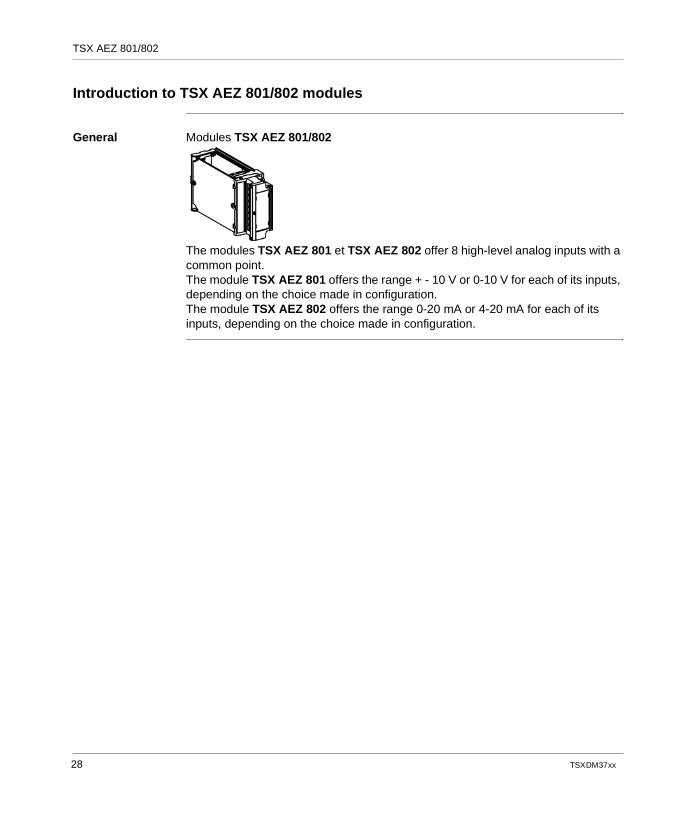
General Modules TSX AEZ 801/802
The modules TSX AEZ 801 et TSX AEZ 802 offer 8 high-level analog inputs with a common point. The module TSX AEZ 801 offers the range + - 10 V or 0-10 V for each of its inputs, depending on the choice made in configuration.The module TSX AEZ 802 offers the range 0-20 mA or 4-20 mA for each of its inputs, depending on the choice made in configuration.
28 TSX DM 37 xx
TSX AEZ 801/802
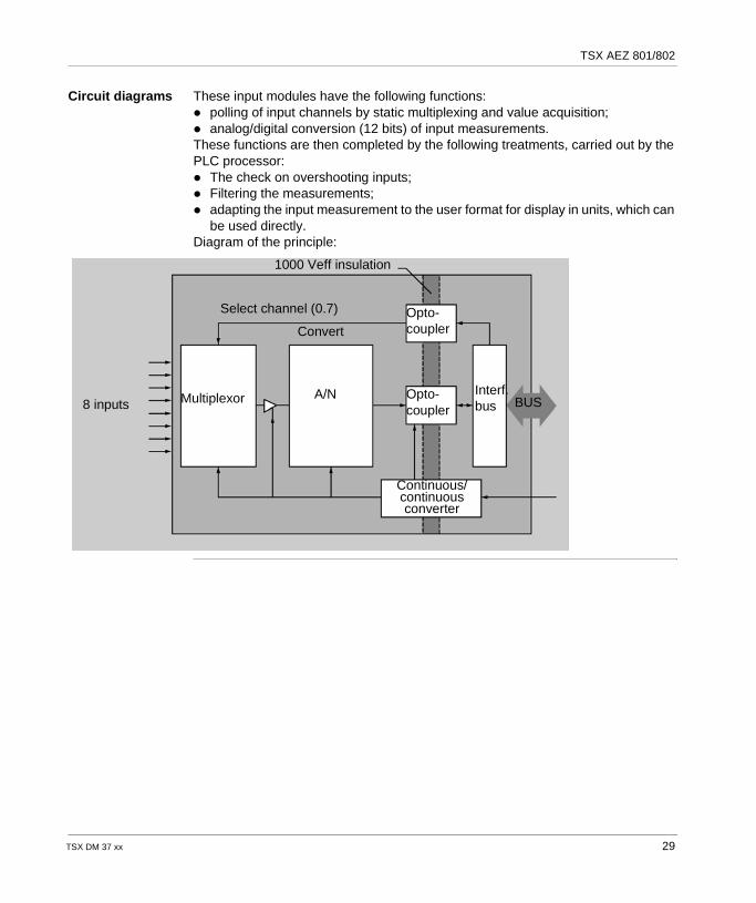
Circuit diagrams These input modules have the following functions: polling of input channels by static multiplexing and value acquisition; analog/digital conversion (12 bits) of input measurements.These functions are then completed by the following treatments, carried out by the PLC processor: The check on overshooting inputs; Filtering the measurements; adapting the input measurement to the user format for display in units, which can
be used directly.Diagram of the principle:
8 inputs
Continuous/continuousconverter
Select channel (0.7) Opto-coupler
Interf.bus
A/NMultiplexor
Convert
1000 Veff insulation
BUSOpto-coupler
TSX DM 37 xx 29
TSX AEZ 801/802
Input processing
General The inputs of the analog module TSX ASZ 801 have the following functions: measurement timing; range selection and overshoot monitoring; sensor link monitoring; module behavior in the event of an overload; measurement filtering; measurement display.
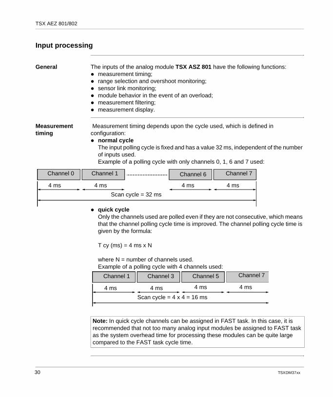
Measurement timing
Measurement timing depends upon the cycle used, which is defined in configuration: normal cycle
The input polling cycle is fixed and has a value 32 ms, independent of the number of inputs used.Example of a polling cycle with only channels 0, 1, 6 and 7 used:
quick cycleOnly the channels used are polled even if they are not consecutive, which means that the channel polling cycle time is improved. The channel polling cycle time is given by the formula:
T cy (ms) = 4 ms x N
where N = number of channels used.Example of a polling cycle with 4 channels used:
Channel 0 Channel 1 Channel 6 Channel 7
4 ms 4 ms4 ms4 ms
Scan cycle = 32 ms
Note: In quick cycle channels can be assigned in FAST task. In this case, it is recommended that not too many analog input modules be assigned to FAST task as the system overhead time for processing these modules can be quite large compared to the FAST task cycle time.
Channel 1 Channel 3 Channel 5 Channel 7
4 ms 4 ms4 ms4 ms
Scan cycle = 4 x 4 = 16 ms
30 TSX DM 37 xx
TSX AEZ 801/802
Range selection and overshoot monitoring
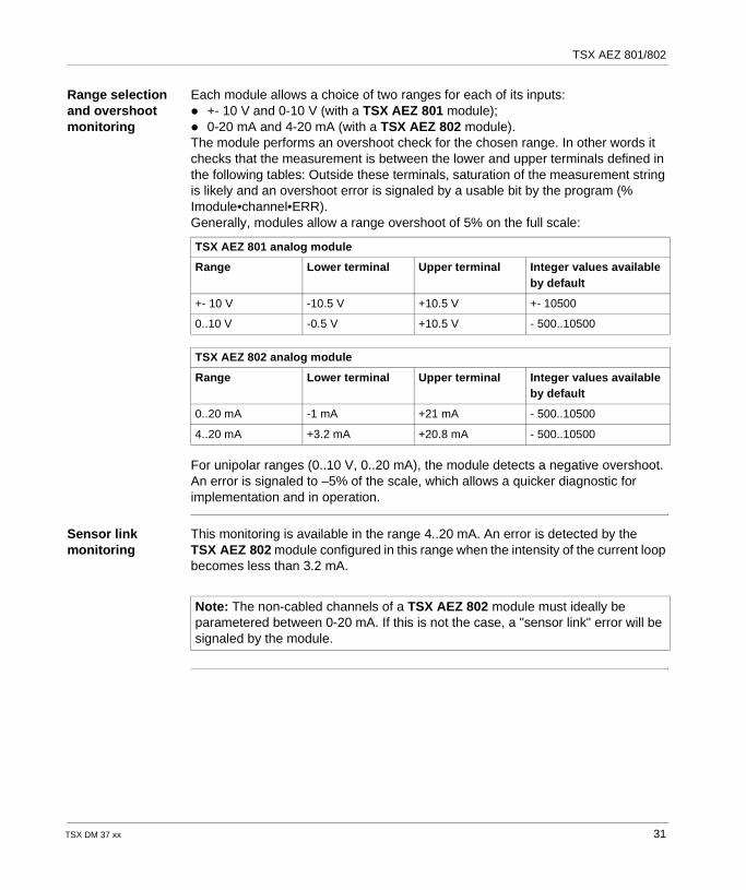
Each module allows a choice of two ranges for each of its inputs: +- 10 V and 0-10 V (with a TSX AEZ 801 module); 0-20 mA and 4-20 mA (with a TSX AEZ 802 module).The module performs an overshoot check for the chosen range. In other words it checks that the measurement is between the lower and upper terminals defined in the following tables: Outside these terminals, saturation of the measurement string is likely and an overshoot error is signaled by a usable bit by the program (% Imodule•channel•ERR).Generally, modules allow a range overshoot of 5% on the full scale:
For unipolar ranges (0..10 V, 0..20 mA), the module detects a negative overshoot. An error is signaled to –5% of the scale, which allows a quicker diagnostic for implementation and in operation.
Sensor link monitoring
This monitoring is available in the range 4..20 mA. An error is detected by the TSX AEZ 802 module configured in this range when the intensity of the current loop becomes less than 3.2 mA.
TSX AEZ 801 analog module
Range Lower terminal Upper terminal Integer values available by default
+- 10 V -10.5 V +10.5 V +- 10500
0..10 V -0.5 V +10.5 V - 500..10500
TSX AEZ 802 analog module
Range Lower terminal Upper terminal Integer values available by default
0..20 mA -1 mA +21 mA - 500..10500
4..20 mA +3.2 mA +20.8 mA - 500..10500
Note: The non-cabled channels of a TSX AEZ 802 module must ideally be parametered between 0-20 mA. If this is not the case, a "sensor link" error will be signaled by the module.
TSX DM 37 xx 31
TSX AEZ 801/802
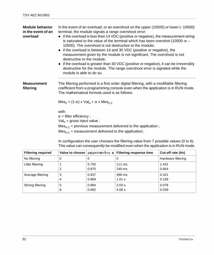
Module behavior in the event of an overload
In the event of an overload, or an overshoot on the upper (10500) or lower (- 10500) terminal, the module signals a range overshoot error: if the overload is less than 14 VDC (positive or negative), the measurement string
is saturated to the value of the terminal which has been overshot (10500 or –10500). The overshoot is not destructive to the module;
if the overload is between 14 and 30 VDC (positive or negative), the measurement given by the module is not significant. The overshoot is not destructive to the module;
if the overload is greater than 30 VDC (positive or negative), it can be irreversibly destructive for the module. The range overshoot error is signaled while the module is able to do so.
Measurement filtering
The filtering performed is a first order digital filtering, with a modifiable filtering coefficient from a programming console even when the application is in RUN mode. The mathematical formula used is as follows:
Mesn = (1-α) x Valn + α x Mesn-1
with:α = filter efficiency ;Valn = gross input value ;Mesn-1 = previous measurement delivered to the application ;Mesn-1 = measurement delivered to the application;
In configuration the user chooses the filtering value from 7 possible values (0 to 6). This value can consequently be modified even when the application is in RUN mode.
Filtering required Value to choose χoρρεσπoνδινγ a Filtering response time Cut-off rate (Hz)
No filtering 0 0 0 Hardware filtering
Little filtering 12
0.7500.875
111 ms240 ms
1.4310.664
Average filtering 34
0.9370.969
496 ms1.01 s
0.3210.158
Strong filtering 56
0.9840.992
2.03 s4.08 s
0.0780.039
32 TSX DM 37 xx
TSX AEZ 801/802
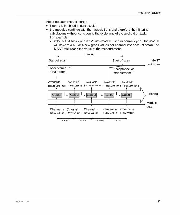
About measurement filtering : filtering is inhibited in quick cycle; the modules continue with their acquisitions and therefore their filtering
calculations without considering the cycle time of the application task.For example: if the MAST task cycle is 120 ms (module used in normal cycle), the module
will have taken 3 or 4 new gross values per channel into account before the MAST task reads the value of the measurement;
Start of scan Start of scan
Acceptance ofmeasurment
Acceptance ofmeasurment
Availablemeasurement
Filtering
Modulescan
MASTtask scan
Calcul CalculCalcul Calcul Calcul
Channel nRaw value
Availablemeasurement
Availablemeasurement
Availablemeasurement
Availablemeasurement
Channel nRaw value
Channel nRaw value
Channel nRaw value
Channel nRaw value
TSX DM 37 xx 33
TSX AEZ 801/802
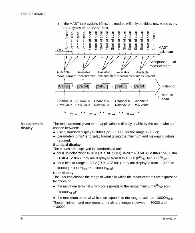
if the MAST task cycle is 10ms, the module will only provide a new value every 3 or 4 cycles of the MAST task.
Measurement display
The measurement given to the application is directly usable by the user who can choose between: using standard display 0-10000 (or +- 10000 for the range +- 10 V); parametering his/her display format giving the minimum and maximum values
required.Standard displayThe values are displayed in standardized units: for a unipolar range 0-10 V (TSX AEZ 801), 0-20 mA (TSX AEZ 802) or 4-20 mA
(TSX AEZ 802), they are displayed from 0 to 10000 (00/000 to 100000/000); for a bipolar range +- 10 V (TSX AEZ 801), they are displayed from - 10000 to +
10000 (- 100000/000 to + 100000/000).User displayThe user can choose the range of values in which the measurements are expressed by choosing:
the minimum terminal which corresponds to the range minimum 00/000 (or -
100000/000):
the maximum terminal which corresponds to the range maximum 100000/000.These minimum and maximum terminals are integers between - 30000 and + 30000.
Sta
rt o
f sca
n
Sta
rt o
f sca
n
Sta
rt o
f sca
n
Sta
rt o
f sca
n
Sta
rt o
f sca
n
Sta
rt o
f sca
n
Sta
rt o
f sca
n
Sta
rt o
f sca
n
Sta
rt o
f sca
n
Sta
rt o
f sca
n
Sta
rt o
f sca
n
Sta
rt o
f sca
n
Sta
rt o
f sca
n
Sta
rt o
f sca
n
Sta
rt o
f sca
n
Sta
rt o
f sca
n
MASTtask scan
Acceptance ofmeasurement
Modulescan
FilteringCalcul CalculCalcul Calcul Calcul
Availablemeasurement
Availablemeasurement
Availablemeasurement
Availablemeasurement
Availablemeasurement
Channel nRaw value
Channel nRaw value
Channel nRaw value
Channel nRaw value
Channel nRaw value
34 TSX DM 37 xx
TSX AEZ 801/802
Fault processing
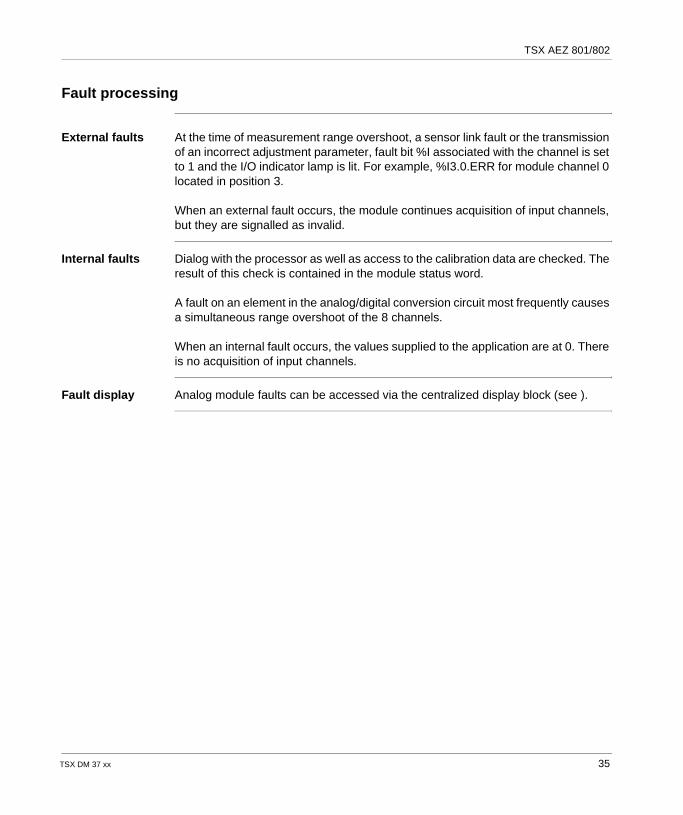
External faults At the time of measurement range overshoot, a sensor link fault or the transmission of an incorrect adjustment parameter, fault bit %I associated with the channel is set to 1 and the I/O indicator lamp is lit. For example, %I3.0.ERR for module channel 0 located in position 3.
When an external fault occurs, the module continues acquisition of input channels, but they are signalled as invalid.
Internal faults Dialog with the processor as well as access to the calibration data are checked. The result of this check is contained in the module status word.
A fault on an element in the analog/digital conversion circuit most frequently causes a simultaneous range overshoot of the 8 channels.
When an internal fault occurs, the values supplied to the application are at 0. There is no acquisition of input channels.
Fault display Analog module faults can be accessed via the centralized display block (see ).
TSX DM 37 xx 35
TSX AEZ 801/802
Characteristics of TSX AEZ 801/802 analog modules
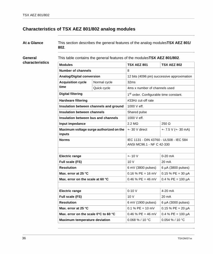
At a Glance This section describes the general features of the analog modulesTSX AEZ 801/802.
General characteristics
This table contains the general features of the modulesTSX AEZ 801/802.
Modules TSX AEZ 801 TSX AEZ 802
Number of channels 8
Analog/Digital conversion 12 bits (4096 pin) successive approximation
Acquisition cycle time
Normal cycle 32ms
Quick cycle 4ms x number of channels used
Digital filtering 1st order. Configurable time constant.
Hardware filtering #33Hz cut-off rate
Insulation between channels and ground 1000 V eff.
Insulation between channels Shared pulse
Insulation between bus and channels 1000 V eff.
Input impedance 2.2 MΩ 250 Ω
Maximum voltage surge authorized on the inputs
+- 30 V direct +- 7.5 V (+- 30 mA)
Norms IEC 1131 - DIN 43760 - UL508 - IEC 584 ANSI MC96.1 - NF C 42-330
Electric range +- 10 V 0-20 mA
Full scale (FS) 10 V 20 mA
Resolution 6 mV (3800 pulses) 6 µA (3800 pulses)
Max. error at 25 °C 0.16 % PE = 16 mV 0.15 % PE = 30 µA
Max. error on the scale at 60 °C 0.46 % PE = 46 mV 0.4 % PE = 100 µA
Electric range 0-10 V 4-20 mA
Full scale (FS) 10 V 20 mA
Resolution 6 mV (1900 pulses) 6 µA (3000 pulses)
Max. error at 25 °C 0.1 % PE = 10 mV 0.15 % PE = 20 µA
Max. error on the scale 0°C to 60 °C 0.46 % PE = 46 mV 0.4 % PE = 100 µA
Maximum temperature deviation 0.068 % / 10 °C 0.054 % / 10 °C
36 TSX DM 37 xx
TSX AEZ 801/802
Connections for TSX AEZ 801/802 analog modules
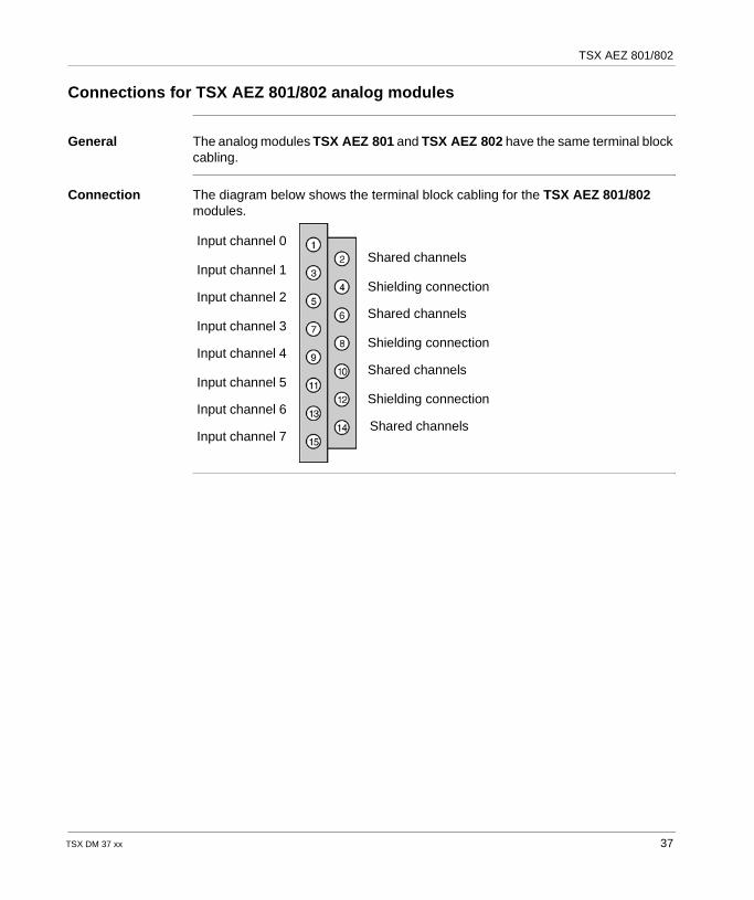
General The analog modules TSX AEZ 801 and TSX AEZ 802 have the same terminal block cabling.
Connection The diagram below shows the terminal block cabling for the TSX AEZ 801/802 modules.
Input channel 0
Input channel 1
Input channel 2
Input channel 3
Input channel 4
Input channel 5
Input channel 6
Input channel 7
Shared channels
Shielding connection
Shared channels
Shielding connection
Shared channels
Shielding connection
Shared channels
TSX DM 37 xx 37

TSX AEZ 801/802
38 TSX DM 37 xx
TSX DM 37 xx
4
The analog input module TSX AEZ 414At a Glance
Aim of this chapter
This chapter describes the TSX AEZ 414 analog input module, its features and its connection system.
What's in this Chapter?
This chapter contains the following topics:
Topic Page
Introduction to the module TSX AEZ 414 40
Input processing 42
Fault processing 48
Features of the analog module TSX AEZ 414 49
Connections for the analog module TSX AEZ 414 52
Cabling recommendations for thermoprobes Pt 100 and Ni1000 55
Cabling and installation recommendations for thermocouples 56
39

TSX AEZ 414
Introduction to the module TSX AEZ 414
General Module TSX AEZ 414.
The TSX AEZ 414 module is a multi-range acquisition string with 4 differential inputs. For each of its inputs and depending on the choice made in configuration, the TSX AEZ 414 module offers the range : thermocouple B, E, J, K, L, N, R, S, T or U ; thermoprobe Pt100 or Ni1000 in 2 or 4 yarns ; high level +- 10 V, 0-10 V, 0-5 V (0-20 mA with an external shunt) or 1-5 V (4-20
mA with an external shunt). It should be noted that external shunts are delivered with the product.
40 TSX DM 37 xx
TSX AEZ 414
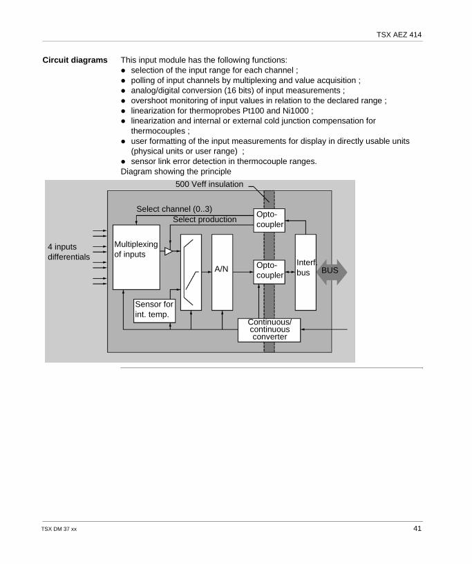
Circuit diagrams This input module has the following functions: selection of the input range for each channel ; polling of input channels by multiplexing and value acquisition ; analog/digital conversion (16 bits) of input measurements ; overshoot monitoring of input values in relation to the declared range ; linearization for thermoprobes Pt100 and Ni1000 ; linearization and internal or external cold junction compensation for
thermocouples ; user formatting of the input measurements for display in directly usable units
(physical units or user range) ; sensor link error detection in thermocouple ranges.Diagram showing the principle
4 inputsdifferentials
Continuous/continuous converter
Select channel (0..3)Opto-coupler
Interf.busA/N
Multiplexingof inputs
Select production
500 Veff insulation
BUSOpto-coupler
Sensor forint. temp.
TSX DM 37 xx 41
TSX AEZ 414
Input processing
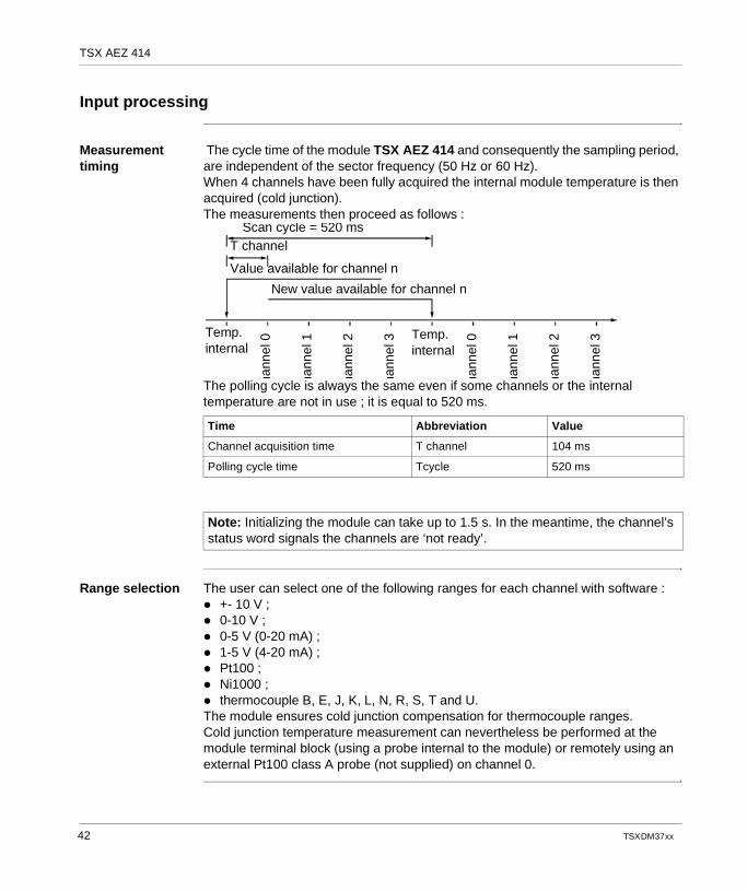
Measurement timing
The cycle time of the module TSX AEZ 414 and consequently the sampling period, are independent of the sector frequency (50 Hz or 60 Hz).When 4 channels have been fully acquired the internal module temperature is then acquired (cold junction).The measurements then proceed as follows :
The polling cycle is always the same even if some channels or the internal temperature are not in use ; it is equal to 520 ms.
Range selection The user can select one of the following ranges for each channel with software : +- 10 V ; 0-10 V ; 0-5 V (0-20 mA) ; 1-5 V (4-20 mA) ; Pt100 ; Ni1000 ; thermocouple B, E, J, K, L, N, R, S, T and U.The module ensures cold junction compensation for thermocouple ranges.Cold junction temperature measurement can nevertheless be performed at the module terminal block (using a probe internal to the module) or remotely using an external Pt100 class A probe (not supplied) on channel 0.
Time Abbreviation Value
Channel acquisition time T channel 104 ms
Polling cycle time Tcycle 520 ms
Note: Initializing the module can take up to 1.5 s. In the meantime, the channel’s status word signals the channels are ‘not ready’.
Scan cycle = 520 msT channel
Value available for channel n
New value available for channel n
hann
el 0
hann
el 1
hann
el 2
hann
el 3
hann
el 0
hann
el 1
hann
el 2
hann
el 3Temp.
internalTemp.internal
42 TSX DM 37 xx
TSX AEZ 414
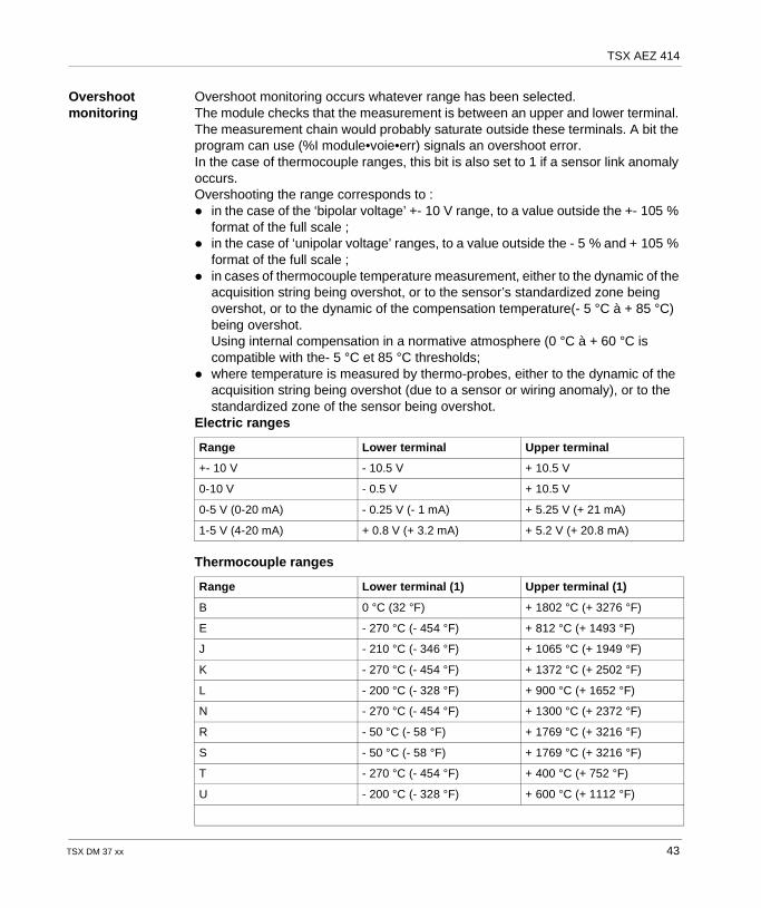
Overshoot monitoring
Overshoot monitoring occurs whatever range has been selected.The module checks that the measurement is between an upper and lower terminal. The measurement chain would probably saturate outside these terminals. A bit the program can use (%I module•voie•err) signals an overshoot error.In the case of thermocouple ranges, this bit is also set to 1 if a sensor link anomaly occurs.Overshooting the range corresponds to : in the case of the ‘bipolar voltage’ +- 10 V range, to a value outside the +- 105 %
format of the full scale ; in the case of ‘unipolar voltage’ ranges, to a value outside the - 5 % and + 105 %
format of the full scale ; in cases of thermocouple temperature measurement, either to the dynamic of the
acquisition string being overshot, or to the sensor’s standardized zone being overshot, or to the dynamic of the compensation temperature(- 5 °C à + 85 °C) being overshot.Using internal compensation in a normative atmosphere (0 °C à + 60 °C is compatible with the- 5 °C et 85 °C thresholds;
where temperature is measured by thermo-probes, either to the dynamic of the acquisition string being overshot (due to a sensor or wiring anomaly), or to the standardized zone of the sensor being overshot.
Electric ranges
Thermocouple ranges
Range Lower terminal Upper terminal
+- 10 V - 10.5 V + 10.5 V
0-10 V - 0.5 V + 10.5 V
0-5 V (0-20 mA) - 0.25 V (- 1 mA) + 5.25 V (+ 21 mA)
1-5 V (4-20 mA) + 0.8 V (+ 3.2 mA) + 5.2 V (+ 20.8 mA)
Range Lower terminal (1) Upper terminal (1)
B 0 °C (32 °F) + 1802 °C (+ 3276 °F)
E - 270 °C (- 454 °F) + 812 °C (+ 1493 °F)
J - 210 °C (- 346 °F) + 1065 °C (+ 1949 °F)
K - 270 °C (- 454 °F) + 1372 °C (+ 2502 °F)
L - 200 °C (- 328 °F) + 900 °C (+ 1652 °F)
N - 270 °C (- 454 °F) + 1300 °C (+ 2372 °F)
R - 50 °C (- 58 °F) + 1769 °C (+ 3216 °F)
S - 50 °C (- 58 °F) + 1769 °C (+ 3216 °F)
T - 270 °C (- 454 °F) + 400 °C (+ 752 °F)
U - 200 °C (- 328 °F) + 600 °C (+ 1112 °F)
TSX DM 37 xx 43
TSX AEZ 414
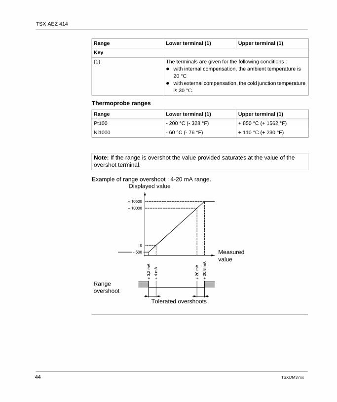
Thermoprobe ranges
Example of range overshoot : 4-20 mA range.
Key
(1) The terminals are given for the following conditions : with internal compensation, the ambient temperature is
20 °C with external compensation, the cold junction temperature
is 30 °C.
Range Lower terminal (1) Upper terminal (1)
Pt100 - 200 °C (- 328 °F) + 850 °C (+ 1562 °F)
Ni1000 - 60 °C (- 76 °F) + 110 °C (+ 230 °F)
Note: If the range is overshot the value provided saturates at the value of the overshot terminal.
Range Lower terminal (1) Upper terminal (1)
Displayed value
Measuredvalue
Tolerated overshoots
Rangeovershoot
44 TSX DM 37 xx
TSX AEZ 414
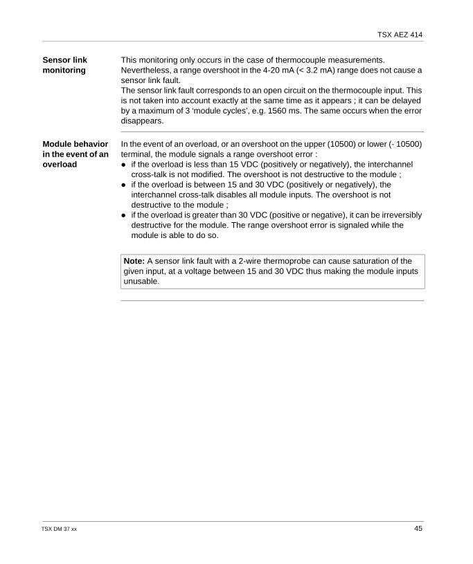
Sensor link monitoring
This monitoring only occurs in the case of thermocouple measurements. Nevertheless, a range overshoot in the 4-20 mA (< 3.2 mA) range does not cause a sensor link fault.The sensor link fault corresponds to an open circuit on the thermocouple input. This is not taken into account exactly at the same time as it appears ; it can be delayed by a maximum of 3 ‘module cycles’, e.g. 1560 ms. The same occurs when the error disappears.
Module behavior in the event of an overload
In the event of an overload, or an overshoot on the upper (10500) or lower (- 10500) terminal, the module signals a range overshoot error : if the overload is less than 15 VDC (positively or negatively), the interchannel
cross-talk is not modified. The overshoot is not destructive to the module ; if the overload is between 15 and 30 VDC (positively or negatively), the
interchannel cross-talk disables all module inputs. The overshoot is not destructive to the module ;
if the overload is greater than 30 VDC (positive or negative), it can be irreversibly destructive for the module. The range overshoot error is signaled while the module is able to do so.
Note: A sensor link fault with a 2-wire thermoprobe can cause saturation of the given input, at a voltage between 15 and 30 VDC thus making the module inputs unusable.
TSX DM 37 xx 45
TSX AEZ 414
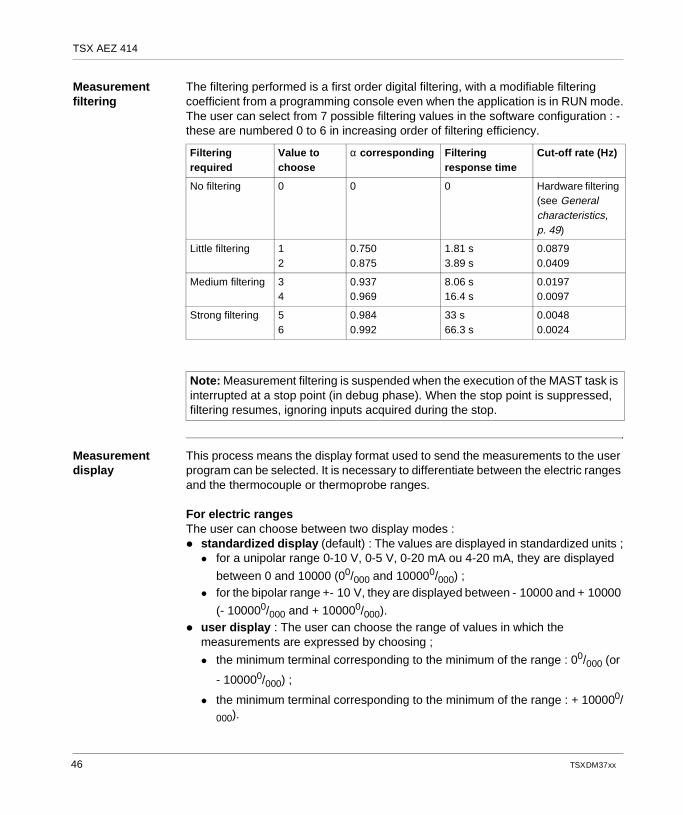
Measurement filtering
The filtering performed is a first order digital filtering, with a modifiable filtering coefficient from a programming console even when the application is in RUN mode.The user can select from 7 possible filtering values in the software configuration : - these are numbered 0 to 6 in increasing order of filtering efficiency.
Measurement display
This process means the display format used to send the measurements to the user program can be selected. It is necessary to differentiate between the electric ranges and the thermocouple or thermoprobe ranges.
For electric rangesThe user can choose between two display modes : standardized display (default) : The values are displayed in standardized units ;
for a unipolar range 0-10 V, 0-5 V, 0-20 mA ou 4-20 mA, they are displayed
between 0 and 10000 (00/000 and 100000/000) ; for the bipolar range +- 10 V, they are displayed between - 10000 and + 10000
(- 100000/000 and + 100000/000). user display : The user can choose the range of values in which the
measurements are expressed by choosing ;
the minimum terminal corresponding to the minimum of the range : 00/000 (or
- 100000/000) ;
the minimum terminal corresponding to the minimum of the range : + 100000/
000).
Filtering required
Value to choose
α corresponding Filtering response time
Cut-off rate (Hz)
No filtering 0 0 0 Hardware filtering (see General characteristics, p. 49)
Little filtering 12
0.7500.875
1.81 s3.89 s
0.08790.0409
Medium filtering 34
0.9370.969
8.06 s16.4 s
0.01970.0097
Strong filtering 56
0.9840.992
33 s66.3 s
0.00480.0024
Note: Measurement filtering is suspended when the execution of the MAST task is interrupted at a stop point (in debug phase). When the stop point is suppressed, filtering resumes, ignoring inputs acquired during the stop.
46 TSX DM 37 xx
TSX AEZ 414
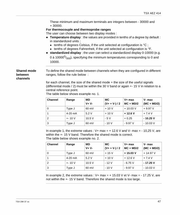
These minimum and maximum terminals are integers between - 30000 and + 30000.
For thermocouple and thermoprobe rangesThe user can choose between two display modes : Temperature display : the values are provided in tenths of a degree by default :
in standardized units ; tenths of degrees Celsius, if the unit selected at configuration is °C ; tenths of degrees Fahrenheit, if the unit selected at configuration is °F.
standardized display : the user can select a standardized display 0-10000 (e.g.
0 à 100000/000), specifying the minimum temperatures corresponding to 0 and 10000.
Shared mode between channels
To define the shared mode between channels when they are configured in different ranges, follow the rule below :
for each channel, the size of the shared mode + the size of the useful signals (differential mode / 2) must be within the 30 V band or again +- 15 V in relation to a central reference point.The table below shows example no. 1.
In example 1, the extreme values : V+ max = + 12.6 V and V- max = - 10,25 V, are within the +- 15 V band. Therefore the shared mode is correct.The table below shows example no. 2.
In example 2, the extreme values : V+ max = + 15.03 V et V- max = - 17.25 V, are not within the +- 15 V band. Therefore the shared mode is too large.
Channel Range MDV+ V-
MC(V+ + V-) / 2
V+ maxMC + MD/2
V- max(MC + MD/2)
0 Type J 60 mV + 10 V + 10.03 V + 9.97 V
1 4-20 mA 5.2 V + 10 V + 12.6 V + 7.4 V
2 +- 10 V 10.5 V - 5 V + 0.25 - 10.25 V
3 Type J 60 mV - 10 V - 9.97 V - 10.03 V
Channel Range MDV+ V-
MC(V+ + V-) / 2
V+ maxMC + MD/2
V- max(MC + MD/2)
0 Type J 60 mV + 15 V + 15.03 V + 14.97 V
1 4-20 mA 5.2 V + 10 V + 12.6 V + 7.4 V
2 +- 10 V 10.5 V - 12 V - 6.75 V - 17.25 V
3 Type J 60 mV - 10 V - 9.97 V - 10.03 V
TSX DM 37 xx 47
TSX AEZ 414
Fault processing
External faults These faults correspond to a range overshoot fault (cold junction temperature input channel) or to a sensor link fault in thermocouple range.When a fault of this type appears, the module status does not change. The channel(s) involved are always acknowledged. However, they are signalled as invalid by the fault bit %I associated with the channel.
Internal faults These faults are the result of the module test performed on initilization or of the test of the measurement system, performed every 5 acquisition scans during normal operation. When a fault of this type appears, the module is inoperative and remains so until it is powered off. The result of the monitoring is contained in the module status word.
Fault display Analog module faults can be accessed via the centralized display block (see ).
Note: The absence of the 24 VR voltage on the "backplane" is translated as an external fault on the TSX AEZ 414 module.
48 TSX DM 37 xx
TSX AEZ 414
Features of the analog module TSX AEZ 414
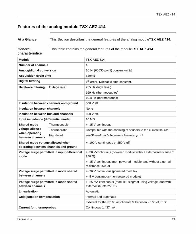
At a Glance This Section describes the general features of the analog moduleTSX AEZ 414.
General characteristics
This table contains the general features of the moduleTSX AEZ 414.
Module TSX AEZ 414
Number of channels 4
Analog/digital conversion 16 bit (65535 point) conversion Σ∆
Acquisition cycle time 520ms
Digital filtering 1st order. Definable time constant.
Hardware filtering Outage rate 255 Hz (high level)
169 Hz (thermocouples)
10.8 Hz (thermoprobes)
Insulation between channels and ground 500 V eff.
Insulation between channels None
Insulation between bus and channels 500 V eff.
Input impedance (differential mode) 10 MΩ
Shared mode voltage allowed when operating between channels
Thermocouple +- 15 V continuous
Thermoprobe Compatible with the chaining of sensors to the current source.
High-level seeShared mode between channels, p. 47
Shared mode voltage allowed when operating between channels and ground
+- 100 V continuous or 250 V eff.
Voltage surge permitted in input differential mode
+- 30 V continuous (powered module without external resistance of 250 Ω)
+- 15 V continuous (non powered module, and without external resistance 250 Ω)
Voltage surge permitted in mode shared between channels
+- 20 V continuous (powered module)
+- 5 V continuous (non powered module)
Voltage surge permitted in mode shared between channels
+- 25 mA continuous (module using/not using voltage, and with external shunts 250 Ω)
Linearization Automatic
Cold junction compensation Internal and automatic
External for the Pt100 on channel 0, between - 5 °C et 85 °C
Current for thermoprobes Continuous 1.437 mA
TSX DM 37 xx 49
TSX AEZ 414
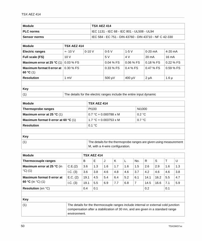
PLC norms IEC 1131 - IEC 68 - IEC 801 - UL508 - UL94
Sensor norms IEC 584 - EC 751 - DIN 43760 - DIN 43710 - NF C 42-330
Module TSX AEZ 414
Electric ranges +- 10 V 0-10 V 0-5 V 1-5 V 0-20 mA 4-20 mA
Full scale (FS) 10 V 5 V 4 V 20 mA 16 mA
Maximum error at 25 °C (1) 0.03 % FS 0.04 % FS 0.06 % FS 0.18 % FS 0.22 % FS
Maximum format 0 error at 60 °C (1)
0.30 % FS 0.33 % FS 0.4 % FS 0.47 % FS 0.59 % FS
Resolution 1 mV 500 µV 400 µV 2 µA 1.6 µ
Key
(1) The details for the electric ranges include the entire input dynamic
Module TSX AEZ 414
Thermoprobe ranges Pt100 Ni1000
Maximum error at 25 °C (1) 0.7 °C + 0.000788 x M 0.2 °C
Maximum format 0 error at 60 °C (1) 1.7 °C + 0.003753 x M 0.7 °C
Resolution 0.1 °C
Key
(1) The details for the thermoprobe ranges are given using measurement M, with a 4-wire configuration.
Module TSX AEZ 414
Thermocouple ranges B E J K L No. R S T U
Maximum error at 25 °C (in °C) (1)
C.E.(2) 3.6 1.3 1.6 1.7 1.6 1.5 2.6 2.9 1.6 1.3
I.C. (3) 3.6 3.8 4.6 4.8 4.6 3.7 4.2 4.6 4.6 3.8
Maximum format 0 error at 60 °C (in °C) (1)
E.C. (2) 19.1 4.5 5.4 6.4 5.2 6.1 14.1 16.2 5.5 4.7
I.C. (3) 19.1 5.5 6.9 7.7 6.8 7 14.5 16.6 7.1 5.9
Resolution (en °C) 0.4 0.1 0.2 0.1
Key
(1) The details for the thermocouple ranges include internal or external cold junction compensation after a stabilization of 30 mn, and are given in a standard range environment.
Module TSX AEZ 414
50 TSX DM 37 xx
TSX AEZ 414
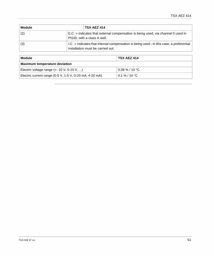
(2) E.C. = indicates that external compensation is being used, via channel 0 used in Pt100, with a class A well.
(3) I.C. = indicates that internal compensation is being used ; in this case, a preferential installation must be carried out.
Module TSX AEZ 414
Maximum temperature deviation
Electric voltage range (+- 10 V, 0-10 V, ...) 0.08 % / 10 °C
Electric current range (0-5 V, 1-5 V, 0-20 mA, 4-20 mA) 0.1 % / 10 °C
Module TSX AEZ 414
TSX DM 37 xx 51
TSX AEZ 414
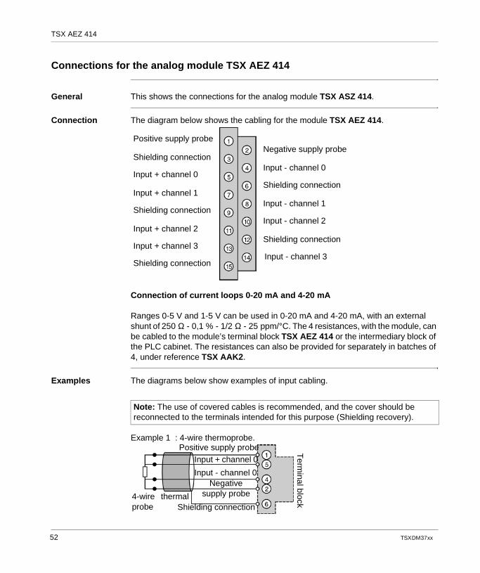
Connections for the analog module TSX AEZ 414
General This shows the connections for the analog module TSX ASZ 414.
Connection The diagram below shows the cabling for the module TSX AEZ 414.
Connection of current loops 0-20 mA and 4-20 mA
Ranges 0-5 V and 1-5 V can be used in 0-20 mA and 4-20 mA, with an external shunt of 250 Ω - 0,1 % - 1/2 Ω - 25 ppm/°C. The 4 resistances, with the module, can be cabled to the module’s terminal block TSX AEZ 414 or the intermediary block of the PLC cabinet. The resistances can also be provided for separately in batches of 4, under reference TSX AAK2.
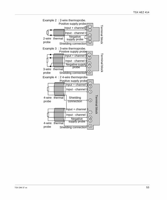
Examples The diagrams below show examples of input cabling.
Example 1 : 4-wire thermoprobe.
Positive supply probe
Shielding connection
Input + channel 0
Input + channel 1
Shielding connection
Input + channel 2
Input + channel 3
Shielding connection
Negative supply probe
Input - channel 0
Shielding connection
Input - channel 1
Input - channel 2
Shielding connection
Input - channel 3
Note: The use of covered cables is recommended, and the cover should be reconnected to the terminals intended for this purpose (Shielding recovery).
Positive supply probeInput + channel 0
Input - channel 0Negative
supply probe
Shielding connection4-wire thermalprobe
Term
inal block
52 TSX DM 37 xx
TSX AEZ 414
Example 2 : 2-wire thermoprobe.
Example 3 : 3-wire thermoprobe.
Example 4 : 2 4-wire thermoprobe.
Positive supply probeInput + channel 0
Input - channel 0Negative
supply probe
Shielding connection
2-wire thermalprobe
Term
inal block
Positive supply probeInput + channel 0
Input - channel 0Negative supply
probe
Shielding connection3-wire thermalprobe
Term
inal block
Positive supply probeInput + channel 0
Input - channel 0
Shieldingconnection
4-wire thermalprobe
Term
inal block
4-wire thermalprobe
Negativesupply probe
Input + channel 1
Input - channel 1
Shielding connection
TSX DM 37 xx 53
TSX AEZ 414
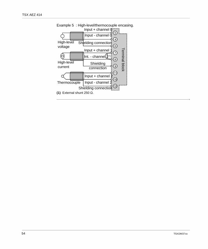
Example 5 : High-level/thermocouple encasing.
(1) External shunt 250 Ω.
Input + channel 0
Input - channel 0
Shielding connection
ThermocoupleT
erminal block
High-levelcurrent
High-levelvoltage
Input + channel 1
Int. - channel 1
Shieldingconnection
Input + channel 2
Input - channel 2
Shielding connection
54 TSX DM 37 xx
TSX AEZ 414
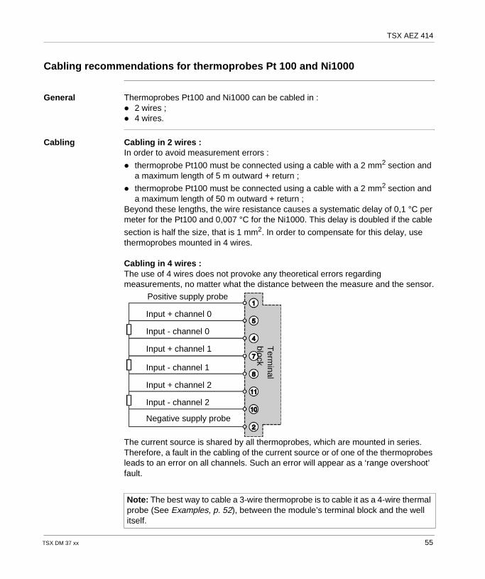
Cabling recommendations for thermoprobes Pt 100 and Ni1000
General Thermoprobes Pt100 and Ni1000 can be cabled in : 2 wires ; 4 wires.
Cabling Cabling in 2 wires :In order to avoid measurement errors :
thermoprobe Pt100 must be connected using a cable with a 2 mm2 section and a maximum length of 5 m outward + return ;
thermoprobe Pt100 must be connected using a cable with a 2 mm2 section and a maximum length of 50 m outward + return ;
Beyond these lengths, the wire resistance causes a systematic delay of 0,1 °C per meter for the Pt100 and 0,007 °C for the Ni1000. This delay is doubled if the cable
section is half the size, that is 1 mm2. In order to compensate for this delay, use thermoprobes mounted in 4 wires.
Cabling in 4 wires :The use of 4 wires does not provoke any theoretical errors regarding measurements, no matter what the distance between the measure and the sensor.
The current source is shared by all thermoprobes, which are mounted in series. Therefore, a fault in the cabling of the current source or of one of the thermoprobes leads to an error on all channels. Such an error will appear as a ‘range overshoot’ fault.
Note: The best way to cable a 3-wire thermoprobe is to cable it as a 4-wire thermal probe (See Examples, p. 52), between the module’s terminal block and the well itself.
Positive supply probe
Negative supply probe
Input + channel 0
Input - channel 0
Input - channel 2
Input + channel 2
Input + channel 1
Input - channel 1
Term
inalblock
TSX DM 37 xx 55
TSX AEZ 414
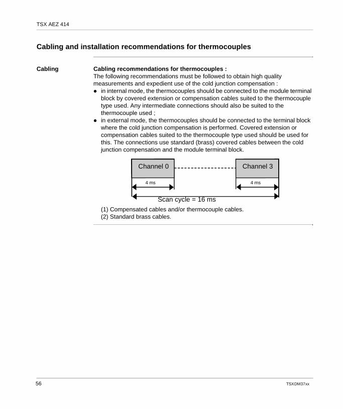
Cabling and installation recommendations for thermocouples
Cabling Cabling recommendations for thermocouples :The following recommendations must be followed to obtain high quality measurements and expedient use of the cold junction compensation : in internal mode, the thermocouples should be connected to the module terminal
block by covered extension or compensation cables suited to the thermocouple type used. Any intermediate connections should also be suited to the thermocouple used ;
in external mode, the thermocouples should be connected to the terminal block where the cold junction compensation is performed. Covered extension or compensation cables suited to the thermocouple type used should be used for this. The connections use standard (brass) covered cables between the cold junction compensation and the module terminal block.
(1) Compensated cables and/or thermocouple cables.(2) Standard brass cables.
Channel 0 Channel 3
4 ms4 ms
Scan cycle = 16 ms
56 TSX DM 37 xx
TSX AEZ 414
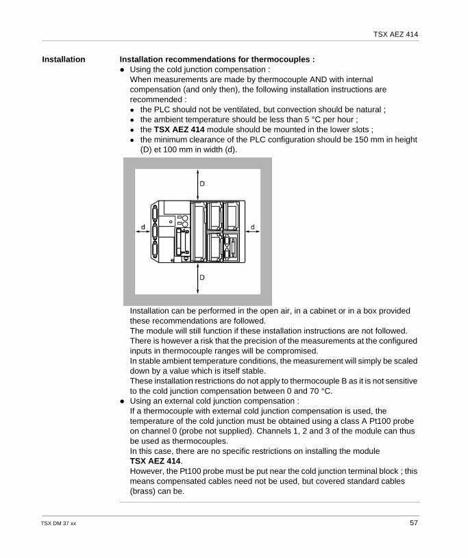
Installation Installation recommendations for thermocouples : Using the cold junction compensation :
When measurements are made by thermocouple AND with internal compensation (and only then), the following installation instructions are recommended : the PLC should not be ventilated, but convection should be natural ; the ambient temperature should be less than 5 °C per hour ; the TSX AEZ 414 module should be mounted in the lower slots ; the minimum clearance of the PLC configuration should be 150 mm in height
(D) et 100 mm in width (d).
Installation can be performed in the open air, in a cabinet or in a box provided these recommendations are followed.The module will still function if these installation instructions are not followed. There is however a risk that the precision of the measurements at the configured inputs in thermocouple ranges will be compromised.In stable ambient temperature conditions, the measurement will simply be scaled down by a value which is itself stable.These installation restrictions do not apply to thermocouple B as it is not sensitive to the cold junction compensation between 0 and 70 °C.
Using an external cold junction compensation :If a thermocouple with external cold junction compensation is used, the temperature of the cold junction must be obtained using a class A Pt100 probe on channel 0 (probe not supplied). Channels 1, 2 and 3 of the module can thus be used as thermocouples.In this case, there are no specific restrictions on installing the module TSX AEZ 414. However, the Pt100 probe must be put near the cold junction terminal block ; this means compensated cables need not be used, but covered standard cables (brass) can be.
TSX DM 37 xx 57

TSX AEZ 414
58 TSX DM 37 xx

TSX DM 37 xx
5
The analog output module TSX ASZ 401At a Glance
Aim of this chapter
This chapter describes the TSX ASZ 401 analog output module, its features and its connection system.
What's in this Chapter?
This chapter contains the following topics:
Topic Page
Introduction to the TSX ASZ 401 module 60
Output processing 61
Fault processing 62
Features of the analog module TSX ASZ 401 63
Connections for the analog module TSX ASZ 401 64
59
TSX ASZ 401
Introduction to the TSX ASZ 401 module
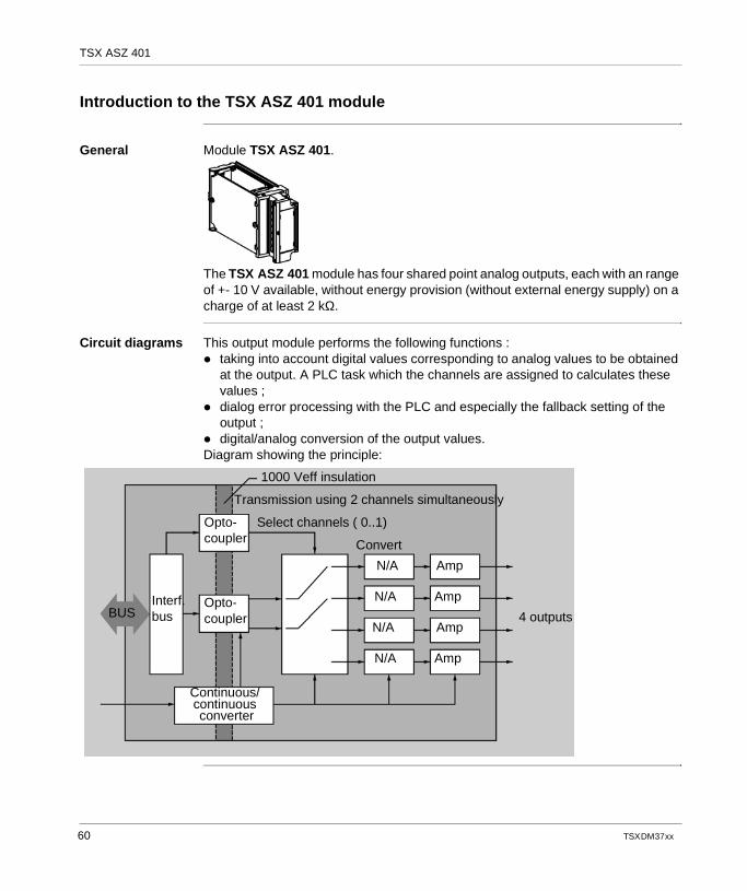
General Module TSX ASZ 401.
The TSX ASZ 401 module has four shared point analog outputs, each with an range of +- 10 V available, without energy provision (without external energy supply) on a charge of at least 2 kΩ.
Circuit diagrams This output module performs the following functions : taking into account digital values corresponding to analog values to be obtained
at the output. A PLC task which the channels are assigned to calculates these values ;
dialog error processing with the PLC and especially the fallback setting of the output ;
digital/analog conversion of the output values.Diagram showing the principle:
4 outputs
Continuous/continuous converter
Select channels ( 0..1)Opto-coupler
Interf.bus
N/A
Transmission using 2 channels simultaneously
1000 Veff insulation
BUSOpto-coupler
N/A
N/A
N/A
Convert
Amp
Amp
Amp
Amp
60 TSX DM 37 xx
TSX ASZ 401
Output processing
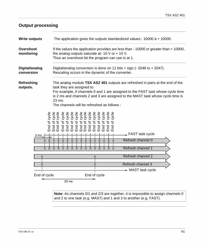
Write outputs The application gives the outputs standardized values:- 10000 à + 10000.
Overshoot monitoring
If the values the application provides are less than - 10000 or greater than + 10000, the analog outputs saturate at- 10 V or + 10 V.Thus an overshoot bit the program can use is at 1.
Digital/analog conversion
Digital/analog conversion is done on 11 bits + sign (- 2048 to + 2047).Rescaling occurs in the dynamic of the converter.
Refreshing outputs.
The analog module TSX ASZ 401 outputs are refreshed in pairs at the end of the task they are assigned to.For example, if channels 0 and 1 are assigned to the FAST task whose cycle time is 2 ms and channels 2 and 3 are assigned to the MAST task whose cycle time is 23 ms:The channels will be refreshed as follows :
End
of c
ycle
End
of c
ycle
End
of c
ycle
End
of c
ycle
End
of c
ycle
End
of c
ycle
End
of c
ycle
End
of c
ycle
End
of c
ycle
End
of c
ycle
End
of c
ycle
End
of c
ycle
End
of c
ycle
End
of c
ycle
End
of c
ycle
FAST task cycle
MAST task cycle
Refresh channel 0
Refresh channel 3
Refresh channel 2
Refresh channel 1
End of cycle End of cycle
Note: As channels 0/1 and 2/3 are together, it is impossible to assign channels 0 and 2 to one task (e.g. MAST) and 1 and 3 to another (e.g. FAST).
TSX DM 37 xx 61
TSX ASZ 401
Fault processing
Output fallback state
When the PLC stops, outputs take the fallback value 0 (4 mA in the range 4-20 mA) or are maintained at the last value transmitted according to the choice made during configuration of the module.
Fault display Analog module faults can be accessed via the central display block (see ).
62 TSX DM 37 xx
TSX ASZ 401
Features of the analog module TSX ASZ 401
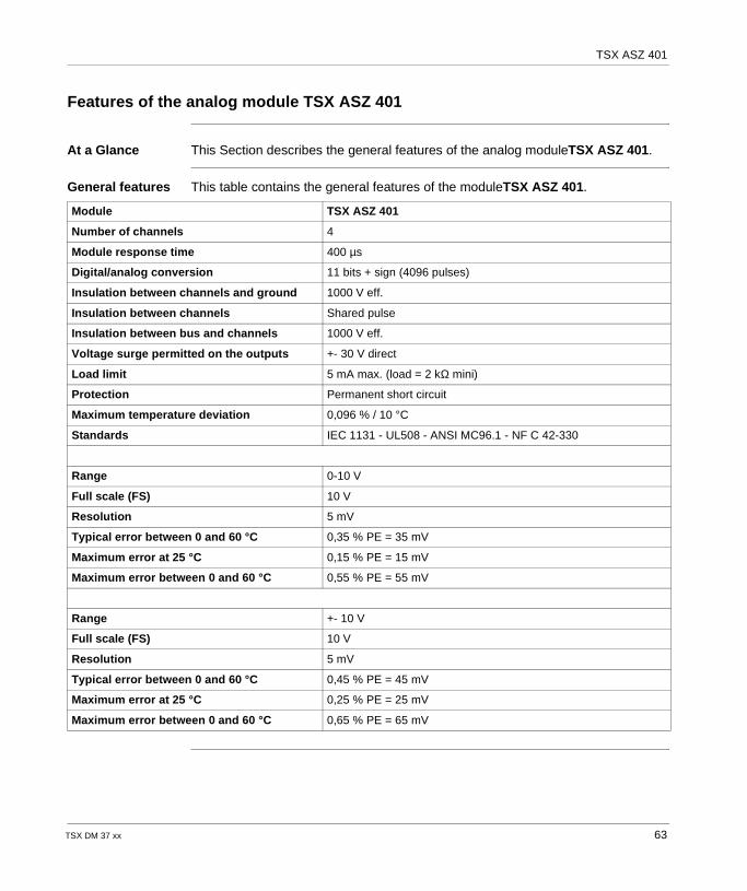
At a Glance This Section describes the general features of the analog moduleTSX ASZ 401.
General features This table contains the general features of the moduleTSX ASZ 401.
Module TSX ASZ 401
Number of channels 4
Module response time 400 µs
Digital/analog conversion 11 bits + sign (4096 pulses)
Insulation between channels and ground 1000 V eff.
Insulation between channels Shared pulse
Insulation between bus and channels 1000 V eff.
Voltage surge permitted on the outputs +- 30 V direct
Load limit 5 mA max. (load = 2 kΩ mini)
Protection Permanent short circuit
Maximum temperature deviation 0,096 % / 10 °C
Standards IEC 1131 - UL508 - ANSI MC96.1 - NF C 42-330
Range 0-10 V
Full scale (FS) 10 V
Resolution 5 mV
Typical error between 0 and 60 °C 0,35 % PE = 35 mV
Maximum error at 25 °C 0,15 % PE = 15 mV
Maximum error between 0 and 60 °C 0,55 % PE = 55 mV
Range +- 10 V
Full scale (FS) 10 V
Resolution 5 mV
Typical error between 0 and 60 °C 0,45 % PE = 45 mV
Maximum error at 25 °C 0,25 % PE = 25 mV
Maximum error between 0 and 60 °C 0,65 % PE = 65 mV
TSX DM 37 xx 63
TSX ASZ 401
Connections for the analog module TSX ASZ 401
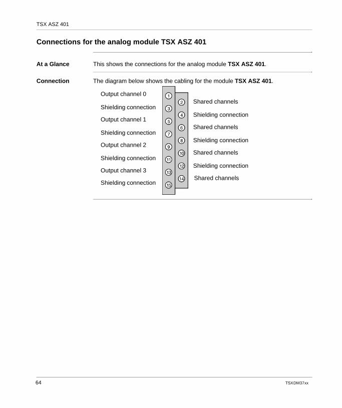
At a Glance This shows the connections for the analog module TSX ASZ 401.
Connection The diagram below shows the cabling for the module TSX ASZ 401.
Output channel 0
Shielding connection
Output channel 1
Shielding connection
Output channel 2
Shielding connection
Output channel 3
Shielding connection
Shared channels
Shielding connection
Shared channels
Shielding connection
Shared channels
Shielding connection
Shared channels
64 TSX DM 37 xx
TSX DM 37 xx
6
The analog output module TSX ASZ 200At a Glance
Aim of this chapter
This chapter describes the TSX ASZ 200 analog output module, its features and its connection system.
What's in this Chapter?
This chapter contains the following topics:
Topic Page
Introduction to the module TSX ASZ 200 66
Output Processing 67
Fault processing 68
Features of the analog module TSX ASZ 200 69
Connections for the analog module TSX ASZ 200 70
65
TSX ASZ 200
Introduction to the module TSX ASZ 200
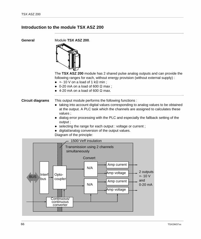
General Module TSX ASZ 200.
The TSX ASZ 200 module has 2 shared pulse analog outputs and can provide the following ranges for each, without energy provision (without external supply) : +- 10 V on a load of 1 kΩ min ; 0-20 mA on a load of 600 Ω max ; 4-20 mA on a load of 600 Ω max.
Circuit diagrams This output module performs the following functions : taking into account digital values corresponding to analog values to be obtained
at the output. A PLC task which the channels are assigned to calculates these values ;
dialog error processing with the PLC and especially the fallback setting of the output ;
selecting the range for each output : voltage or current ; digital/analog conversion of the output values.Diagram of the principle:
2 outputs+- 10 Vand0-20 mA
Continuous/continuous converter
Interf.bus
Transmission using 2 channels simultaneously
1500 Veff insulation
BUSOpto-coupler
N/A
N/A
Convert
Amp current
Amp voltage
Amp current
Amp voltage
66 TSX DM 37 xx
TSX ASZ 200
Output Processing
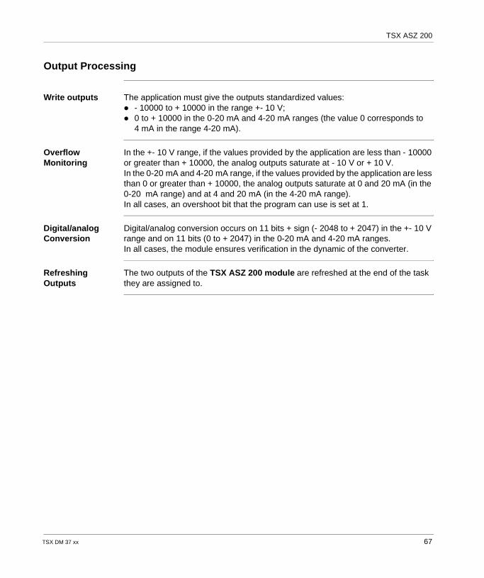
Write outputs The application must give the outputs standardized values: - 10000 to + 10000 in the range +- 10 V; 0 to + 10000 in the 0-20 mA and 4-20 mA ranges (the value 0 corresponds to
4 mA in the range 4-20 mA).
Overflow Monitoring
In the +- 10 V range, if the values provided by the application are less than - 10000 or greater than + 10000, the analog outputs saturate at - 10 V or + 10 V.In the 0-20 mA and 4-20 mA range, if the values provided by the application are less than 0 or greater than + 10000, the analog outputs saturate at 0 and 20 mA (in the 0-20 mA range) and at 4 and 20 mA (in the 4-20 mA range).In all cases, an overshoot bit that the program can use is set at 1.
Digital/analog Conversion
Digital/analog conversion occurs on 11 bits + sign (- 2048 to + 2047) in the +- 10 V range and on 11 bits (0 to + 2047) in the 0-20 mA and 4-20 mA ranges.In all cases, the module ensures verification in the dynamic of the converter.
Refreshing Outputs
The two outputs of the TSX ASZ 200 module are refreshed at the end of the task they are assigned to.
TSX DM 37 xx 67
TSX ASZ 200
Fault processing
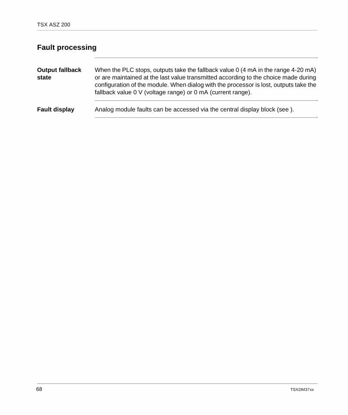
Output fallback state
When the PLC stops, outputs take the fallback value 0 (4 mA in the range 4-20 mA) or are maintained at the last value transmitted according to the choice made during configuration of the module. When dialog with the processor is lost, outputs take the fallback value 0 V (voltage range) or 0 mA (current range).
Fault display Analog module faults can be accessed via the central display block (see ).
68 TSX DM 37 xx
TSX ASZ 200
Features of the analog module TSX ASZ 200
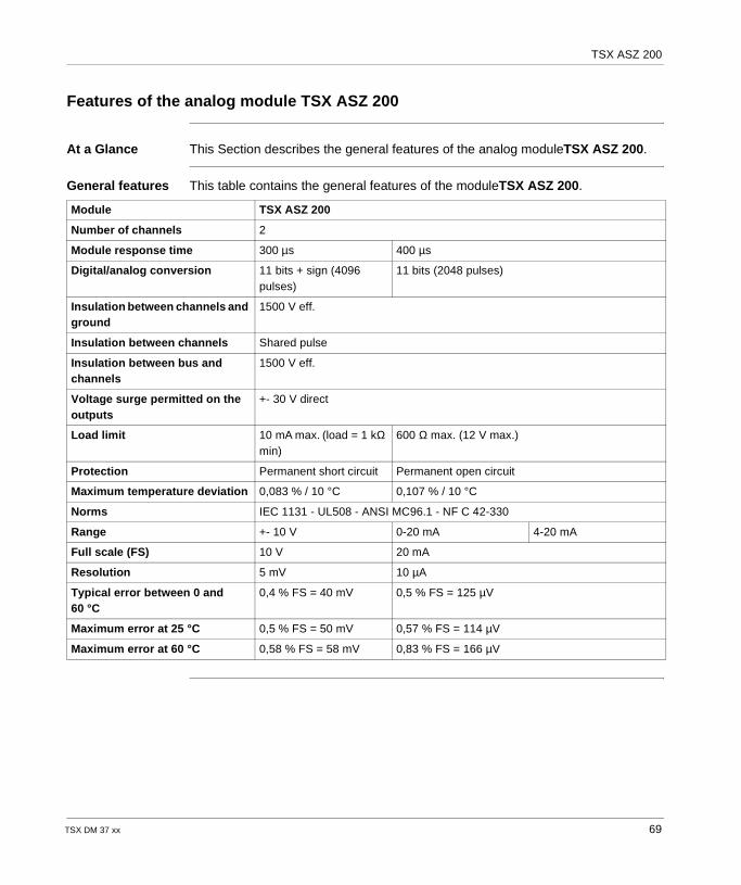
At a Glance This Section describes the general features of the analog moduleTSX ASZ 200.
General features This table contains the general features of the moduleTSX ASZ 200.
Module TSX ASZ 200
Number of channels 2
Module response time 300 µs 400 µs
Digital/analog conversion 11 bits + sign (4096 pulses)
11 bits (2048 pulses)
Insulation between channels and ground
1500 V eff.
Insulation between channels Shared pulse
Insulation between bus and channels
1500 V eff.
Voltage surge permitted on the outputs
+- 30 V direct
Load limit 10 mA max. (load = 1 kΩ min)
600 Ω max. (12 V max.)
Protection Permanent short circuit Permanent open circuit
Maximum temperature deviation 0,083 % / 10 °C 0,107 % / 10 °C
Norms IEC 1131 - UL508 - ANSI MC96.1 - NF C 42-330
Range +- 10 V 0-20 mA 4-20 mA
Full scale (FS) 10 V 20 mA
Resolution 5 mV 10 µA
Typical error between 0 and 60 °C
0,4 % FS = 40 mV 0,5 % FS = 125 µV
Maximum error at 25 °C 0,5 % FS = 50 mV 0,57 % FS = 114 µV
Maximum error at 60 °C 0,58 % FS = 58 mV 0,83 % FS = 166 µV
TSX DM 37 xx 69
TSX ASZ 200
Connections for the analog module TSX ASZ 200
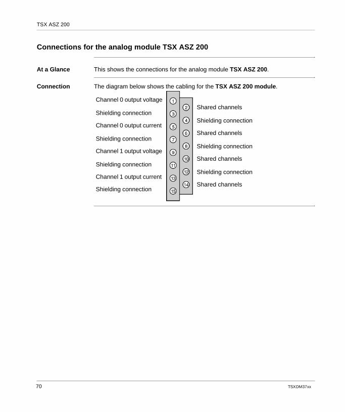
At a Glance This shows the connections for the analog module TSX ASZ 200.
Connection The diagram below shows the cabling for the TSX ASZ 200 module.
Channel 0 output voltage
Shielding connection
Channel 0 output current
Shielding connection
Channel 1 output voltage
Shielding connection
Channel 1 output current
Shielding connection
Shared channels
Shielding connection
Shared channels
Shielding connection
Shared channels
Shielding connection
Shared channels
70 TSX DM 37 xx
TSX DM 37 xx
7
TSX AMZ 600 Analog Input ModulesAt a Glance
Aim of this Chapter
This chapter describes the TSX AMZ 600 analog input module, as well as its characteristics and its connection system.
What's in this Chapter?
This chapter contains the following topics:
Topic Page
Introduction to the TSX AMZ 600 Module 72
Input Processing 74
Output Processing 80
Characteristics of the TSX AMZ 600 Module 81
Connecting the TSX AMZ 600 Analog Module 83
71
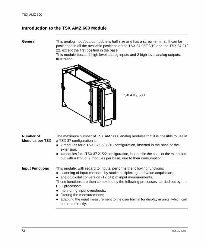
TSX AMZ 600
Introduction to the TSX AMZ 600 Module
General This analog input/output module is half size and has a screw terminal. It can be positioned in all the available positions of the TSX 37 05/08/10 and the TSX 37 21/22, except the first position in the base.This module boasts 4 high level analog inputs and 2 high level analog outputs. Illustration:
Number of Modules per TSX
The maximum number of TSX AMZ 600 analog modules that it is possible to use in a TSX 37 configuration is: 2 modules for a TSX 37 05/08/10 configuration, inserted in the base or the
extension, 4 modules for a TSX 37 21/22 configuration, inserted in the base or the extension,
but with a limit of 2 modules per base, due to their consumption.
Input Functions This module, with regard to inputs, performs the following functions: scanning of input channels by static multiplexing and value acquisition; analog/digital conversion (12 bits) of input measurements.These functions are then completed by the following processes; carried out by the PLC processor: monitoring input overshoots; filtering the measurements; adapting the input measurement to the user format for display in units, which can
be used directly.
TSX AMZ 600
72 TSX DM 37 xx
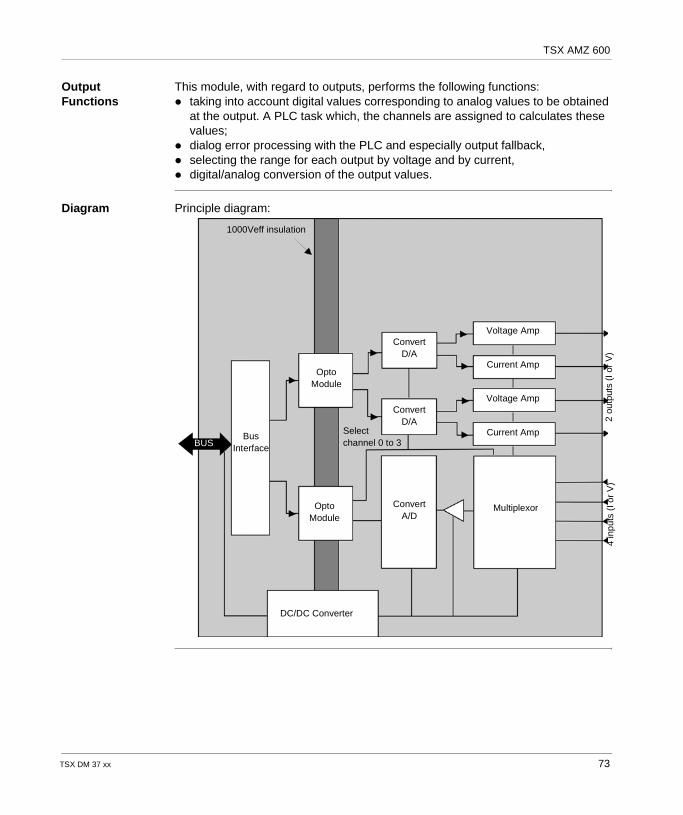
TSX AMZ 600
Output Functions
This module, with regard to outputs, performs the following functions: taking into account digital values corresponding to analog values to be obtained
at the output. A PLC task which, the channels are assigned to calculates these values;
dialog error processing with the PLC and especially output fallback, selecting the range for each output by voltage and by current, digital/analog conversion of the output values.
Diagram Principle diagram:
1000Veff insulation
BUSBus
Interface
OptoModule
ConvertD/A
ConvertA/D
Multiplexor
Selectchannel 0 to 3
Voltage Amp
Current Amp
4 in
puts
(I o
r V
)2
outp
uts
(I o
r V
)
ConvertD/A
OptoModule
DC/DC Converter
Current Amp
Voltage Amp
TSX DM 37 xx 73
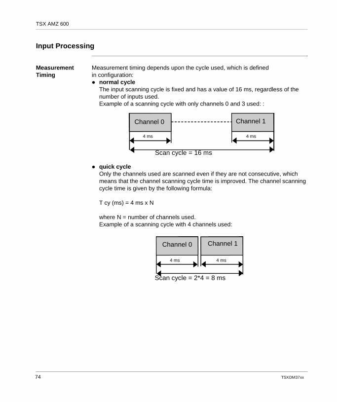
TSX AMZ 600
Input Processing
Measurement Timing
Measurement timing depends upon the cycle used, which is defined in configuration: normal cycle
The input scanning cycle is fixed and has a value of 16 ms, regardless of the number of inputs used.Example of a scanning cycle with only channels 0 and 3 used: :
quick cycleOnly the channels used are scanned even if they are not consecutive, which means that the channel scanning cycle time is improved. The channel scanning cycle time is given by the following formula:
T cy (ms) = 4 ms x N
where N = number of channels used.Example of a scanning cycle with 4 channels used:
Channel 0 Channel 1
4 ms4 ms
Scan cycle = 16 ms
Channel 0 Channel 1
4 ms 4 ms
Scan cycle = 2*4 = 8 ms
74 TSX DM 37 xx
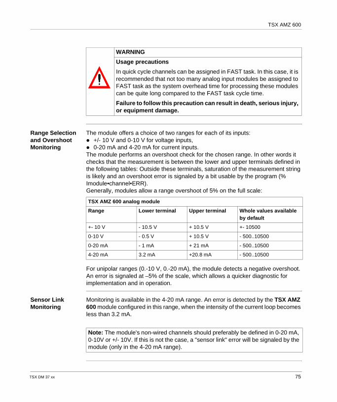
TSX AMZ 600
Range Selection and Overshoot Monitoring
The module offers a choice of two ranges for each of its inputs: +/- 10 V and 0-10 V for voltage inputs, 0-20 mA and 4-20 mA for current inputs.The module performs an overshoot check for the chosen range. In other words it checks that the measurement is between the lower and upper terminals defined in the following tables: Outside these terminals, saturation of the measurement string is likely and an overshoot error is signaled by a bit usable by the program (% Imodule•channel•ERR).Generally, modules allow a range overshoot of 5% on the full scale:
For unipolar ranges (0.-10 V, 0.-20 mA), the module detects a negative overshoot. An error is signaled at –5% of the scale, which allows a quicker diagnostic for implementation and in operation.
Sensor Link Monitoring
Monitoring is available in the 4-20 mA range. An error is detected by the TSX AMZ 600 module configured in this range, when the intensity of the current loop becomes less than 3.2 mA.
WARNING
Usage precautions
In quick cycle channels can be assigned in FAST task. In this case, it is recommended that not too many analog input modules be assigned to FAST task as the system overhead time for processing these modules can be quite long compared to the FAST task cycle time.
Failure to follow this precaution can result in death, serious injury, or equipment damage.
TSX AMZ 600 analog module
Range Lower terminal Upper terminal Whole values available by default
+- 10 V - 10.5 V + 10.5 V +- 10500
0-10 V - 0.5 V + 10.5 V - 500..10500
0-20 mA - 1 mA + 21 mA - 500..10500
4-20 mA 3.2 mA +20.8 mA - 500..10500
Note: The module's non-wired channels should preferably be defined in 0-20 mA, 0-10V or +/- 10V. If this is not the case, a "sensor link" error will be signaled by the module (only in the 4-20 mA range).
TSX DM 37 xx 75
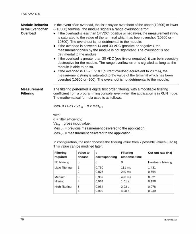
TSX AMZ 600
Module Behavior in the Event of an Overload
In the event of an overload, that is to say an overshoot of the upper (10500) or lower (- 10500) terminal, the module signals a range overshoot error: if the overload is less than 14 VDC (positive or negative), the measurement string
is saturated to the value of the terminal which has been overshot (10500 or –10500). The overshoot is not detrimental to the module;
if the overload is between 14 and 30 VDC (positive or negative), the measurement given by the module is not significant. The overshoot is not detrimental to the module;
if the overload is greater than 30 VDC (positive or negative), it can be irreversibly destructive for the module. The range overflow error is signaled as long as the module is able to do so.
if the overload is +/ -7.5 VDC (current overload equivalent to 20 mA), the measurement string is saturated to the value of the terminal which has been overshot (10500 or -500). The overshoot is not detrimental to the module.
Measurement Filtering
The filtering performed is digital first order filtering, with a modifiable filtering coefficient from a programming console, even when the application is in RUN mode. The mathematical formula used is as follows:
Mesn = (1-α) x Valn + α x Mesn-1
with :α = filter efficiency;Valn = gross input value;Mesn-1 = previous measurement delivered to the application;Mesn-1 = measurement delivered to the application.
In configuration, the user chooses the filtering value from 7 possible values (0 to 6). This value can be modified later.
Filtering required
Value to choose
α corresponding
Filtering response time
Cut-out rate (Hz)
No filtering 0 0 0 Hardware filtering
Little filtering 12
0,7500,875
111 ms240 ms
1,4310,664
Medium filtering
34
0,9370,969
496 ms1.01 s
0,3210,158
High filtering 56
0,9840,992
2.03 s4,08 s
0,0780,039
76 TSX DM 37 xx
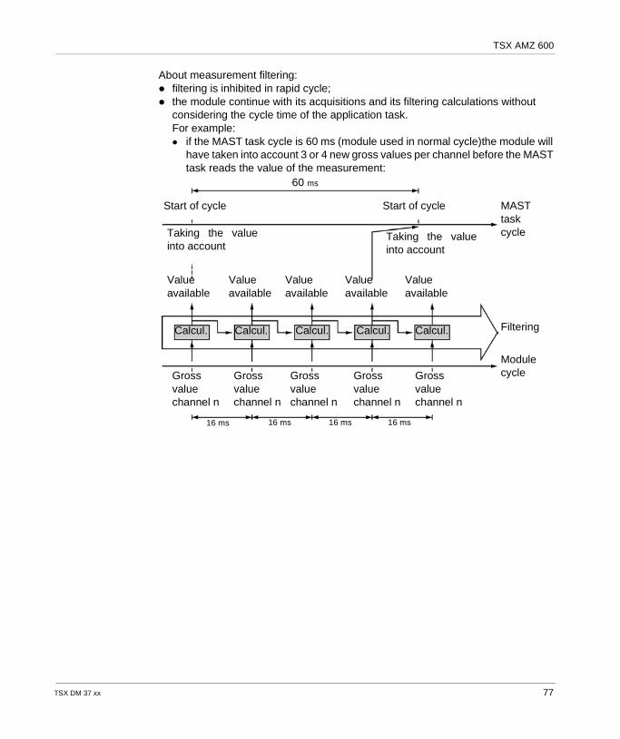
TSX AMZ 600
About measurement filtering: filtering is inhibited in rapid cycle; the module continue with its acquisitions and its filtering calculations without
considering the cycle time of the application task.For example: if the MAST task cycle is 60 ms (module used in normal cycle)the module will
have taken into account 3 or 4 new gross values per channel before the MAST task reads the value of the measurement:
Start of cycle Start of cycle
Taking the valueinto account
Taking the valueinto account
Valueavailable
Valueavailable
Valueavailable
Valueavailable
Valueavailable
Filtering
Modulecycle
MASTtaskcycle
Calcul. Calcul.Calcul. Calcul. Calcul.
Grossvaluechannel n
Grossvaluechannel n
Grossvaluechannel n
Grossvaluechannel n
Grossvaluechannel n
16 ms 16 ms 16 ms 16 ms
60 ms
TSX DM 37 xx 77
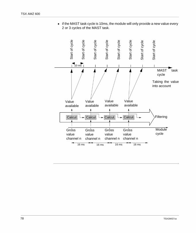
TSX AMZ 600
if the MAST task cycle is 10ms, the module will only provide a new value every 2 or 3 cycles of the MAST task.
Sta
rt o
f cyc
le
Sta
rt o
f cyc
le
Sta
rt o
f cyc
le
Sta
rt o
f cyc
le
Sta
rt o
f cyc
le
Sta
rt o
f cyc
le
Sta
rt o
f cyc
le
Sta
rt o
f cyc
le
MAST taskcycle
Taking the valueinto account
Module cycle
Filtering
Valueavailable
Valueavailable
Valueavailable
Valueavailable
Calcul. Calcul. Calcul. Calcul.
Grossvaluechannel n
Grossvaluechannel n
Grossvaluechannel n
Grossvaluechannel n
16 ms 16 ms 16 ms 16 ms
10 ms
78 TSX DM 37 xx
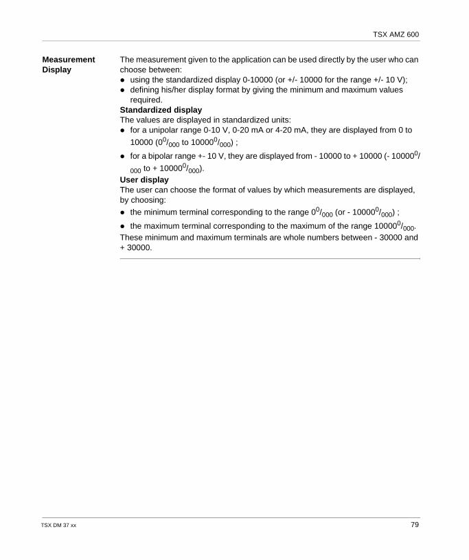
TSX AMZ 600
Measurement Display
The measurement given to the application can be used directly by the user who can choose between: using the standardized display 0-10000 (or +/- 10000 for the range +/- 10 V); defining his/her display format by giving the minimum and maximum values
required.Standardized displayThe values are displayed in standardized units: for a unipolar range 0-10 V, 0-20 mA or 4-20 mA, they are displayed from 0 to
10000 (00/000 to 100000/000) ;
for a bipolar range +- 10 V, they are displayed from - 10000 to + 10000 (- 100000/
000 to + 100000/000).User displayThe user can choose the format of values by which measurements are displayed, by choosing:
the minimum terminal corresponding to the range 00/000 (or - 100000/000) ;
the maximum terminal corresponding to the maximum of the range 100000/000.These minimum and maximum terminals are whole numbers between - 30000 and + 30000.
TSX DM 37 xx 79
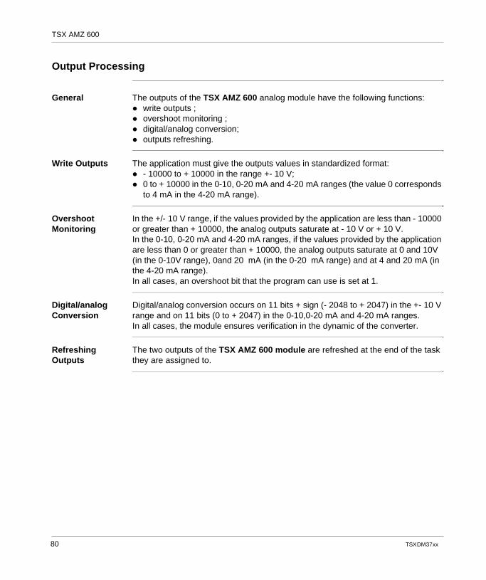
TSX AMZ 600
Output Processing
General The outputs of the TSX AMZ 600 analog module have the following functions: write outputs ; overshoot monitoring ; digital/analog conversion; outputs refreshing.
Write Outputs The application must give the outputs values in standardized format: - 10000 to + 10000 in the range +- 10 V; 0 to + 10000 in the 0-10, 0-20 mA and 4-20 mA ranges (the value 0 corresponds
to 4 mA in the 4-20 mA range).
Overshoot Monitoring
In the +/- 10 V range, if the values provided by the application are less than - 10000 or greater than + 10000, the analog outputs saturate at - 10 V or + 10 V.In the 0-10, 0-20 mA and 4-20 mA ranges, if the values provided by the application are less than 0 or greater than + 10000, the analog outputs saturate at 0 and 10V (in the 0-10V range), 0and 20 mA (in the 0-20 mA range) and at 4 and 20 mA (in the 4-20 mA range).In all cases, an overshoot bit that the program can use is set at 1.
Digital/analog Conversion
Digital/analog conversion occurs on 11 bits + sign (- 2048 to + 2047) in the +- 10 V range and on 11 bits (0 to + 2047) in the 0-10,0-20 mA and 4-20 mA ranges.In all cases, the module ensures verification in the dynamic of the converter.
Refreshing Outputs
The two outputs of the TSX AMZ 600 module are refreshed at the end of the task they are assigned to.
80 TSX DM 37 xx
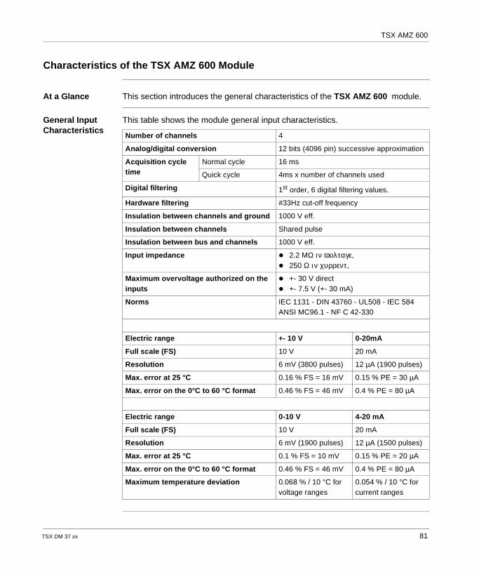
TSX AMZ 600
Characteristics of the TSX AMZ 600 Module
At a Glance This section introduces the general characteristics of the TSX AMZ 600 module.
General Input Characteristics
This table shows the module general input characteristics.
Number of channels 4
Analog/digital conversion 12 bits (4096 pin) successive approximation
Acquisition cycle time
Normal cycle 16 ms
Quick cycle 4ms x number of channels used
Digital filtering 1st order, 6 digital filtering values.
Hardware filtering #33Hz cut-off frequency
Insulation between channels and ground 1000 V eff.
Insulation between channels Shared pulse
Insulation between bus and channels 1000 V eff.
Input impedance 2.2 MΩ ιν ϖολταγε, 250 Ω ιν χυρρεντ ,
Maximum overvoltage authorized on the inputs
+- 30 V direct +- 7.5 V (+- 30 mA)
Norms IEC 1131 - DIN 43760 - UL508 - IEC 584 ANSI MC96.1 - NF C 42-330
Electric range +- 10 V 0-20mA
Full scale (FS) 10 V 20 mA
Resolution 6 mV (3800 pulses) 12 µA (1900 pulses)
Max. error at 25 °C 0.16 % FS = 16 mV 0.15 % PE = 30 µA
Max. error on the 0°C to 60 °C format 0.46 % FS = 46 mV 0.4 % PE = 80 µA
Electric range 0-10 V 4-20 mA
Full scale (FS) 10 V 20 mA
Resolution 6 mV (1900 pulses) 12 µA (1500 pulses)
Max. error at 25 °C 0.1 % FS = 10 mV 0.15 % PE = 20 µA
Max. error on the 0°C to 60 °C format 0.46 % FS = 46 mV 0.4 % PE = 80 µA
Maximum temperature deviation 0.068 % / 10 °C for voltage ranges
0.054 % / 10 °C for current ranges
TSX DM 37 xx 81
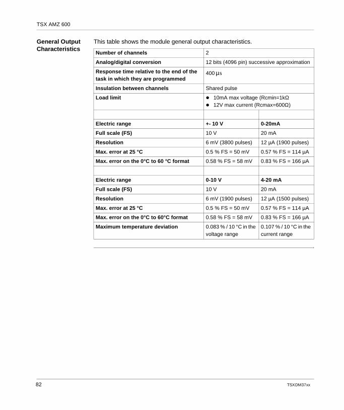
TSX AMZ 600
General Output Characteristics
This table shows the module general output characteristics.
Number of channels 2
Analog/digital conversion 12 bits (4096 pin) successive approximation
Response time relative to the end of the task in which they are programmed
400
Insulation between channels Shared pulse
Load limit 10mA max voltage (Rcmin=1kΩ 12V max current (Rcmax=600Ω)
Electric range +- 10 V 0-20mA
Full scale (FS) 10 V 20 mA
Resolution 6 mV (3800 pulses) 12 µA (1900 pulses)
Max. error at 25 °C 0.5 % FS = 50 mV 0.57 % FS = 114 µA
Max. error on the 0°C to 60 °C format 0.58 % FS = 58 mV 0.83 % FS = 166 µA
Electric range 0-10 V 4-20 mA
Full scale (FS) 10 V 20 mA
Resolution 6 mV (1900 pulses) 12 µA (1500 pulses)
Max. error at 25 °C 0.5 % FS = 50 mV 0.57 % FS = 114 µA
Max. error on the 0°C to 60°C format 0.58 % FS = 58 mV 0.83 % FS = 166 µA
Maximum temperature deviation 0.083 % / 10 °C in the voltage range
0.107 % / 10 °C in the current range
µs
82 TSX DM 37 xx
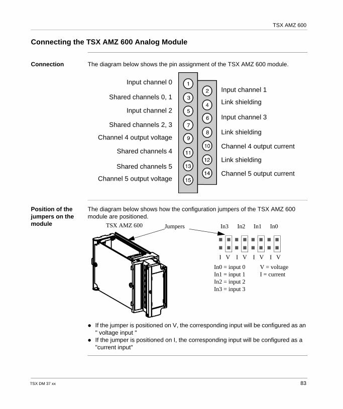
TSX AMZ 600
Connecting the TSX AMZ 600 Analog Module
Connection The diagram below shows the pin assignment of the TSX AMZ 600 module.
Position of the jumpers on the module
The diagram below shows how the configuration jumpers of the TSX AMZ 600 module are positioned.
If the jumper is positioned on V, the corresponding input will be configured as an " voltage input "
If the jumper is positioned on I, the corresponding input will be configured as a "current input"
Input channel 1Input channel 0
Input channel 2Input channel 3
Shared channels 4
Shared channels 0, 1
Shared channels 2, 3
Shared channels 5
Link shielding
Link shielding
Link shielding
Channel 4 output current
Channel 5 output currentChannel 5 output voltage
Channel 4 output voltage
In3 In2 In1 In0
I V I V I V I V
In0 = input 0In1 = input 1In2 = input 2In3 = input 3
V = voltageI = current
TSX AMZ 600 Jumpers
TSX DM 37 xx 83

TSX AMZ 600
84 TSX DM 37 xx
TSX DM 37 xx
II
Counter modulesAt a Glance
General This chapter is about counter modules.
What's in this Part?
This part contains the following chapters:
Chapter Chapter Name Page
8 Counter modules: Introduction 87
9 Counter modules: Standard functions 93
10 Implementing up counting 109
11 TELEFAST 2 connection base: ABE-7CPA01 137
12 TELEFAST 2 connection base: ABE-7H08R10/7H16R20 145
13 Wiring accessories for incremental encoder: TSX TAP S15•• 151
85

Counter modules
86 TSX DM 37 xx
TSX DM 37 xx
8
Counter modules: IntroductionAt a Glance
Aim of this chapter
This chapter serves as a general introduction to TSX CTZ counter modules... .
What's in this Chapter?
This chapter contains the following topics:
Topic Page
Counter modules: General 88
Physical description 90
Installation and assembly of the TSX CTZ 1A/2A/2AA modules 91
87
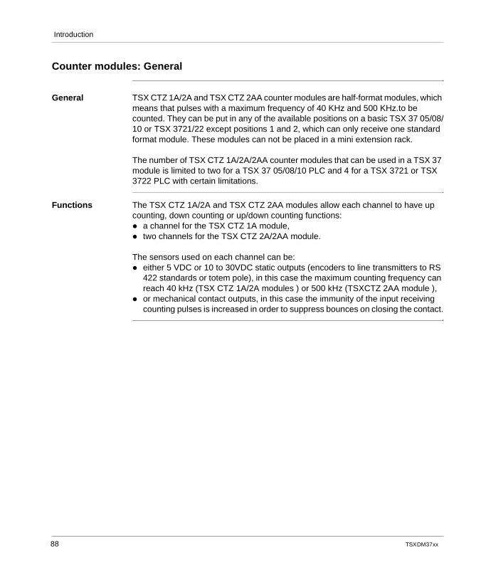
Introduction
Counter modules: General
General TSX CTZ 1A/2A and TSX CTZ 2AA counter modules are half-format modules, which means that pulses with a maximum frequency of 40 KHz and 500 KHz.to be counted. They can be put in any of the available positions on a basic TSX 37 05/08/10 or TSX 3721/22 except positions 1 and 2, which can only receive one standard format module. These modules can not be placed in a mini extension rack.
The number of TSX CTZ 1A/2A/2AA counter modules that can be used in a TSX 37 module is limited to two for a TSX 37 05/08/10 PLC and 4 for a TSX 3721 or TSX 3722 PLC with certain limitations.
Functions The TSX CTZ 1A/2A and TSX CTZ 2AA modules allow each channel to have up counting, down counting or up/down counting functions: a channel for the TSX CTZ 1A module, two channels for the TSX CTZ 2A/2AA module.
The sensors used on each channel can be: either 5 VDC or 10 to 30VDC static outputs (encoders to line transmitters to RS
422 standards or totem pole), in this case the maximum counting frequency can reach 40 kHz (TSX CTZ 1A/2A modules ) or 500 kHz (TSXCTZ 2AA module ),
or mechanical contact outputs, in this case the immunity of the input receiving counting pulses is increased in order to suppress bounces on closing the contact.
88 TSX DM 37 xx
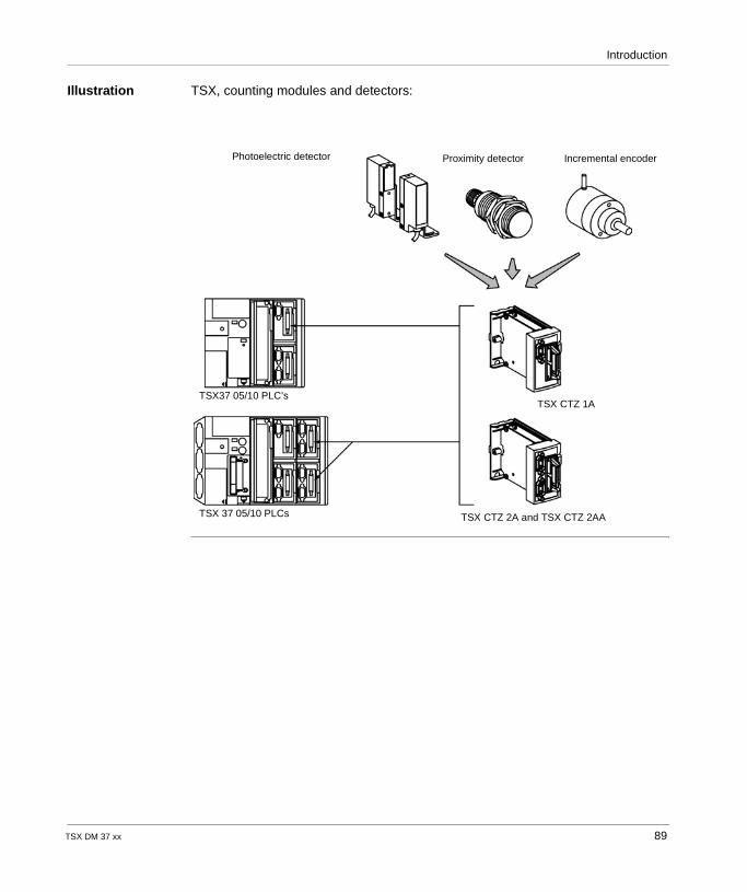
Introduction
Illustration TSX, counting modules and detectors:
Proximity detectorPhotoelectric detector
TSX CTZ 2A and TSX CTZ 2AA
TSX37 05/10 PLC’s
TSX 37 05/10 PLCs
Incremental encoder
TSX CTZ 1A
TSX DM 37 xx 89
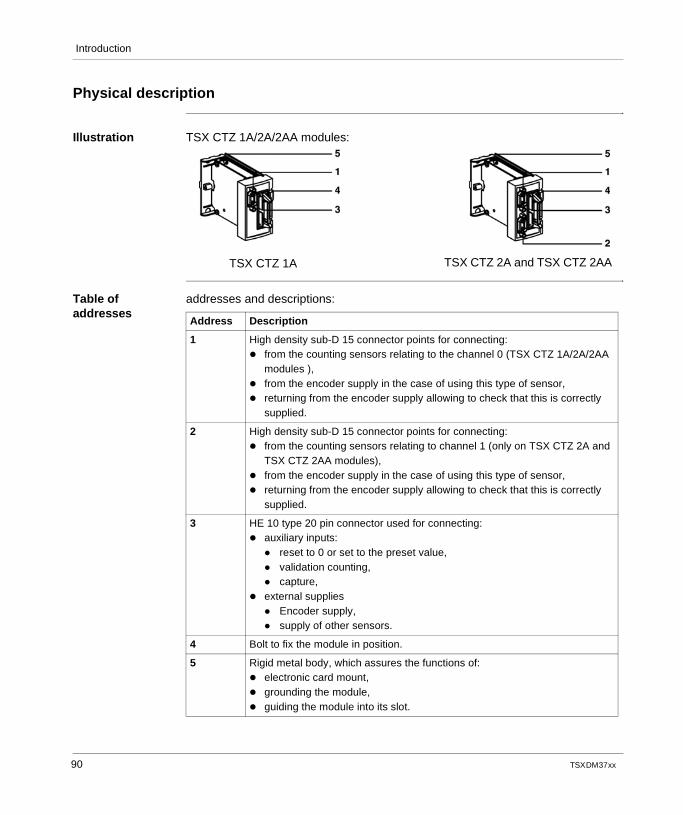
Introduction
Physical description
Illustration TSX CTZ 1A/2A/2AA modules:
Table of addresses
addresses and descriptions:
TSX CTZ 1A TSX CTZ 2A and TSX CTZ 2AA
Address Description
1 High density sub-D 15 connector points for connecting: from the counting sensors relating to the channel 0 (TSX CTZ 1A/2A/2AA
modules ), from the encoder supply in the case of using this type of sensor, returning from the encoder supply allowing to check that this is correctly
supplied.
2 High density sub-D 15 connector points for connecting: from the counting sensors relating to channel 1 (only on TSX CTZ 2A and
TSX CTZ 2AA modules), from the encoder supply in the case of using this type of sensor, returning from the encoder supply allowing to check that this is correctly
supplied.
3 HE 10 type 20 pin connector used for connecting: auxiliary inputs:
reset to 0 or set to the preset value, validation counting, capture,
external supplies Encoder supply, supply of other sensors.
4 Bolt to fix the module in position.
5 Rigid metal body, which assures the functions of: electronic card mount, grounding the module, guiding the module into its slot.
90 TSX DM 37 xx
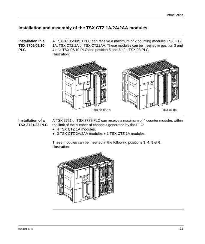
Introduction
Installation and assembly of the TSX CTZ 1A/2A/2AA modules
Installation in a TSX 3705/08/10 PLC
A TSX 37 05/08/10 PLC can receive a maximum of 2 counting modules TSX CTZ 1A, TSX CTZ 2A or TSX CTZ2AA. These modules can be inserted in position 3 and 4 of a TSX 05/10 PLC and position 5 and 6 of a TSX 08 PLC.Illustration:
Installation of a TSX 3721/22 PLC
A TSX 3721 or TSX 3722 PLC can receive a maximum of 4 counter modules within the limit of the number of channels generated by the PLC: 4 TSX CTZ 1A modules, 3 TSX CTZ 2A/2AA modules + 1 TSX CTZ 1A modules.
These modules can be inserted in the following positions 3, 4, 5 et 6.Illustration:
TSX DM 37 xx 91
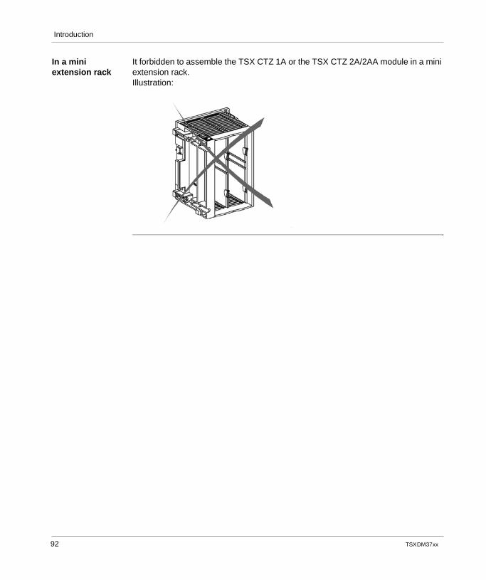
Introduction
In a mini extension rack
It forbidden to assemble the TSX CTZ 1A or the TSX CTZ 2A/2AA module in a mini extension rack.Illustration:
92 TSX DM 37 xx
TSX DM 37 xx
9
Counter modules: Standard functionsAt a Glance
Aim of this chapter
This chapter introduces the different standard features of the TSX CTZ 1A/2A/2AA counter module.
What's in this Chapter?
This chapter contains the following topics:
Topic Page
Down-counter function 94
Up-counting function 95
Up/down counting function 96
Up/down counting on TSX CTZ 1A/2A/2AA modules 97
Principle Diagram 99
Up/down counting on TSX CTZ 1A/2A/2AA modules 100
Provisional diagram 1 103
Provisional diagram 2 104
Provisional diagram 3 105
Provisional diagram 4 106
How the EPSR is connected 107
93
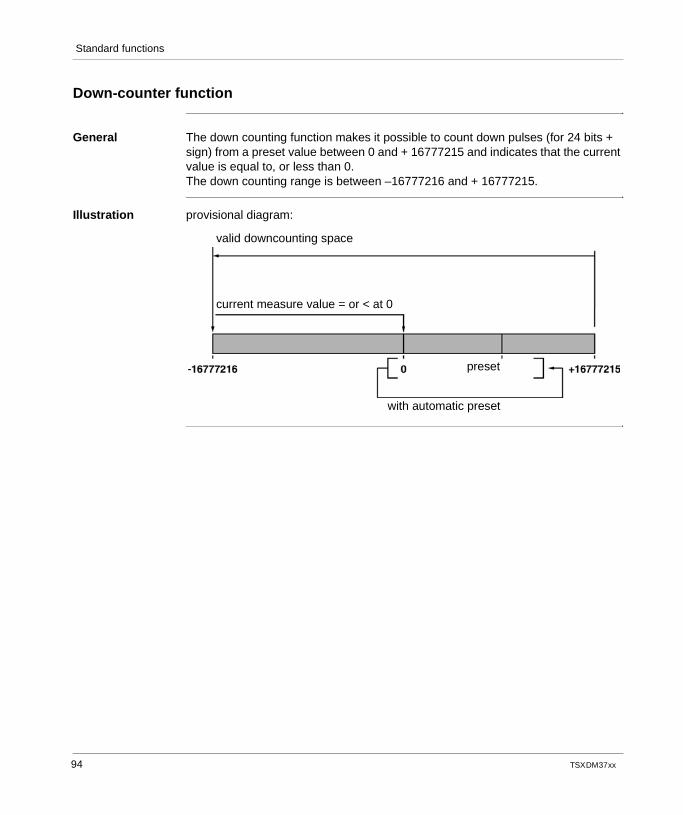
Standard functions
Down-counter function
General The down counting function makes it possible to count down pulses (for 24 bits + sign) from a preset value between 0 and + 16777215 and indicates that the current value is equal to, or less than 0.The down counting range is between –16777216 and + 16777215.
Illustration provisional diagram:
valid downcounting space
current measure value = or < at 0
preset
with automatic preset
94 TSX DM 37 xx
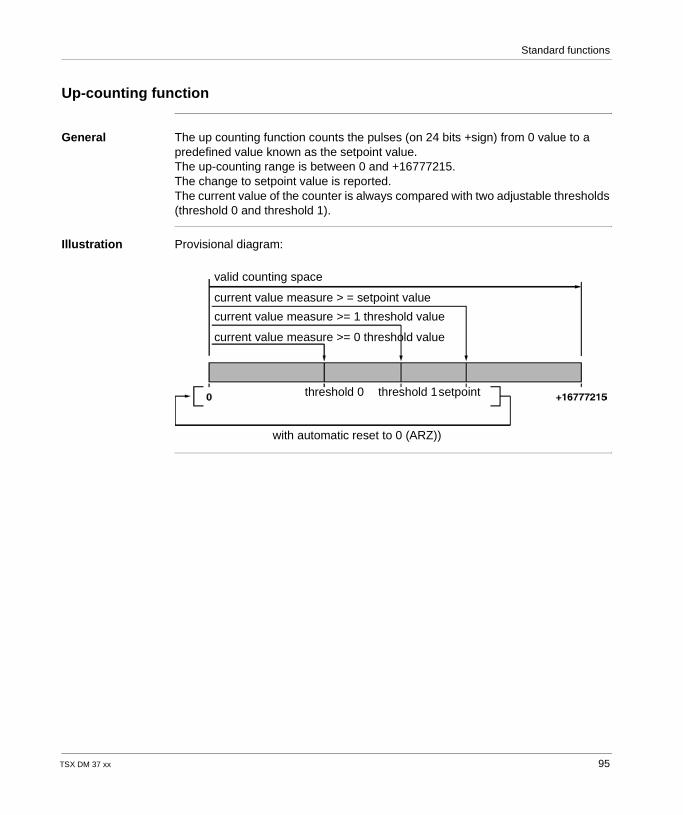
Standard functions
Up-counting function
General The up counting function counts the pulses (on 24 bits +sign) from 0 value to a predefined value known as the setpoint value.The up-counting range is between 0 and +16777215.The change to setpoint value is reported. The current value of the counter is always compared with two adjustable thresholds (threshold 0 and threshold 1).
Illustration Provisional diagram:
valid counting space
current value measure > = setpoint value
current value measure >= 1 threshold value
current value measure >= 0 threshold value
threshold 0 threshold 1setpoint
with automatic reset to 0 (ARZ))
TSX DM 37 xx 95
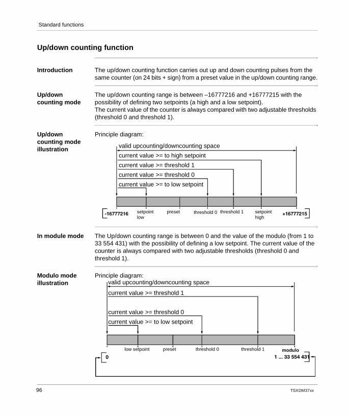
Standard functions
Up/down counting function
Introduction The up/down counting function carries out up and down counting pulses from the same counter (on 24 bits + sign) from a preset value in the up/down counting range.
Up/down counting mode
The up/down counting range is between –16777216 and +16777215 with the possibility of defining two setpoints (a high and a low setpoint).The current value of the counter is always compared with two adjustable thresholds (threshold 0 and threshold 1).
Up/down counting mode illustration
Principle diagram:
In module mode The Up/down counting range is between 0 and the value of the modulo (from 1 to 33 554 431) with the possibility of defining a low setpoint. The current value of the counter is always compared with two adjustable thresholds (threshold 0 and threshold 1).
Modulo mode illustration
Principle diagram:
valid upcounting/downcounting space
current value >= to high setpoint
current value >= threshold 1
current value >= threshold 0
current value >= to low setpoint
setpointlow
preset threshold 0 threshold 1 setpointhigh
valid upcounting/downcounting space
current value >= threshold 1
current value >= threshold 0
current value >= to low setpoint
low setpoint preset threshold 0 modulothreshold 1
96 TSX DM 37 xx
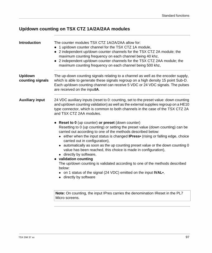
Standard functions
Up/down counting on TSX CTZ 1A/2A/2AA modules
Introduction The counter modules TSX CTZ 1A/2A/2AA allow for: 1 up/down counter channel for the TSX CTZ 1A module, 2 independent up/down counter channels for the TSX CTZ 2A module; the
maximum counting frequency on each channel being 40 khz, 2 independent up/down counter channels for the TSX CTZ 2AA module; the
maximum counting frequency on each channel being 500 khz,
Up/down counting signals
The up-down counting signals relating to a channel as well as the encoder supply, which is able to generate these signals regroup on a high density 15 point Sub-D. Each up/down counting channel can receive 5 VDC or 24 VDC signals. The pulses are received on the inputIA.
Auxiliary input 24 VDC auxiliary inputs (reset to 0: counting, set to the preset value: down counting and up/down counting validation) as well as the external supplies regroup on a HE10 type connector, which is common to both channels in the case of the TSX CTZ 2A and TSX CTZ 2AA modules.
Reset to 0 (up counter) or preset (down counter)Resetting to 0 (up counting) or setting the preset value (down counting) can be carried out according to one of the methods described below: either when the input status is changed IPress• (rising or falling edge, choice
carried out in configuration), automatically as soon as the up counting preset value or the down counting 0
value has been reached, this choice is made in configuration), directly by software,
validation countingThe up/down counting is validated according to one of the methods described below: on 1 status of the signal (24 VDC) emitted on the input IVAL•, directly by software
Note: On counting, the input IPres carries the denomination IReset in the PL7 Micro screens.
TSX DM 37 xx 97
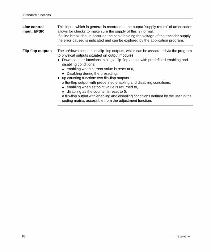
Standard functions
Line control input: EPSR
This input, which in general is recorded at the output "supply return" of an encoder allows for checks to make sure the supply of this is normal.If a line break should occur on the cable holding the voltage of the encoder supply, the error caused is indicated and can be explored by the application program.
Flip-flop outputs The up/down counter has flip-flop outputs, which can be associated via the program to physical outputs situated on output modules. Down counter functions: a single flip-flop output with predefined enabling and
disabling conditions: enabling when current value is reset to 0, Disabling during the presetting,
up counting function: two flip-flop outputsa flip-flop output with predefined enabling and disabling conditions: enabling when setpoint value is returned to, disabling as the counter is reset to 0,a flip-flop output with enabling and disabling conditions defined by the user in the coding matrix, accessible from the adjustment function.
98 TSX DM 37 xx
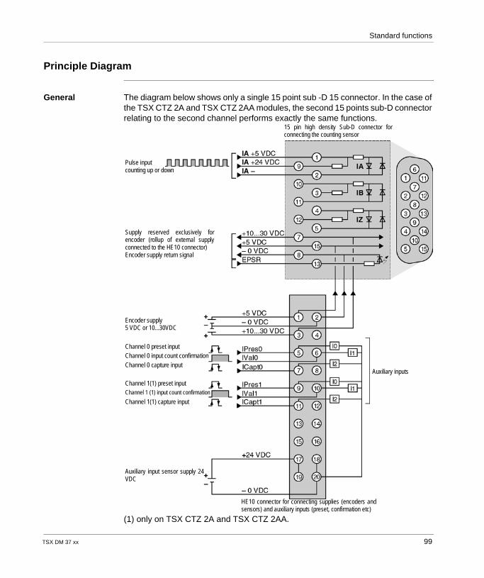
Standard functions
Principle Diagram
General The diagram below shows only a single 15 point sub -D 15 connector. In the case of the TSX CTZ 2A and TSX CTZ 2AA modules, the second 15 points sub-D connector relating to the second channel performs exactly the same functions.
(1) only on TSX CTZ 2A and TSX CTZ 2AA.
15 pin high density Sub-D connector forconnecting the counting sensor
Pulse inputcounting up or down
Supply reserved exclusively forencoder (rollup of external supplyconnected to the HE10 connector)Encoder supply return signal
Encoder supply5 VDC or 10...30VDC
Channel 0 preset inputChannel 0 input count confirmationChannel 0 capture input
Channel 1(1) preset inputChannel 1 (1) input count confirmation
Channel 1(1) capture input
Auxiliary input sensor supply 24VDC
HE10 connector for connecting supplies (encoders andsensors) and auxiliary inputs (preset, confirmation etc)
Auxiliary inputs
TSX DM 37 xx 99
Standard functions
Up/down counting on TSX CTZ 1A/2A/2AA modules
Introduction The counter modules TSX CTZ 1A/2A/2AA allow for: 1 up/down counter channel for the TSX CTZ 1A module, 2 independent up/down counter channels for the TSX CTZ 2A module,
the maximum frequency on each channel is 40 kHz, 2 independent up/down counter channels for the TSX CTZ 2AA module,
the maximum frequency on each channel is 500 kHz.
Up/down counting signals
There are several possibilities, which can be used on each channel: First possibility: (See Provisional diagram 1, p. 103)
When using a single physical up/down counting input, the direction (up or down counting) is defined by the application by positioning a status 0 or 1 bit object Each up/down counting channel can receive 5VDC or 24VDC signals. The up/down counting pulses are received on the inputIA:
Second possibility: (See Provisional diagram 2, p. 104)When using a single up/down counting physical input, the direction (up or down counting) is defined by positioning the second input in status 0 or 1. The up/down counting pulses are received on the inputIA:
Third possibility: (See Provisional diagram 3, p. 105)Using two physical inputs, an up-counting input and a down-counting input: the up counting pulses are received on the IAinput, the down counting pulses are received on the IBinput.
Fourth possibility: (See Provisional diagram 4, p. 106)Using two physical inputs with shifted signals Pi/2 (incremental encoder signals): the up counting signals are received on the IA input for the A signals and on IB for the B signals.In this case, it is possible to choose a function in configuration, which can be multiplied by 1 or 4: for the TSX CTZ 1A/2A modules the maximum frequency of the physical
counting inputs is 40 kHz (multiplied by 1) and 40 kHz (multiplied by 4), for the TSX CTZ2AA modules the maximum frequency of the physical
counting inputs is 500 kHz (multiplied by 1) and 125 kHz (multiplied by 4).
Note: The pulses on the IA input will be up counted if the IB input has been at 1 for more than 3 micro-seconds, the pulses on the IA input will be down counted if the input IB has been at 0 for more than 3 micro-seconds.
Note: All pulses on IA and IB are up counted whatever the synchronism of the signals.
100 TSX DM 37 xx
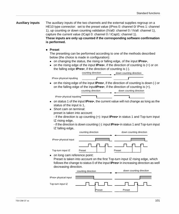
Standard functions
Auxiliary inputs The auxiliary inputs of the two channels and the external supplies regroup on a HE10 type connector: set to the preset value (IPres 0: channel 0/ IPres 1: channel 1), up counting or down counting validation (IVal0: channel 0 / IVall: channel 1), capture the current value (ICapt 0: channel 0 / ICapt1: channel 1).These inputs are only up counted if the corresponding software confirmation is performed.
PresetThe presetting can be performed according to one of the methods described below (the choice is made in configuration): on changing the status, the rising or falling edge, of the input IPres•, on the rising edge of the input IPres•, if the direction of counting is (+) or on
the falling edge IPres•, if the direction of counting is (-).
on the rising edge of the input IPres•, if the direction of counting is down (-) or on the falling edge of the inputIPres•, if the direction of counting is (+).
on status 1 of the input IPres•, the current value will not change as long as the status of the input is 1,
Short cam on terminal:preset is taken into account:- if the direction is up counting (+): input IPres• in status 1 and Top-turn input IZ rising edge,- if the direction is down counting (-): input IPres• in status 1 and Top-turn input IZ falling edge,
on long cam reference point:Preset is taken into account on the first Top-turn input IZ rising edge, which follows the change to status 0 of the input IPres• in increasing direction as well decreasing direction.
counting direction down counting direction
IPres• physical inputting
counting direction down counting direction
IPres• physical inputting
counting direction down counting direction
Preset Preset
IPres• physical input
Top-turn input IZ
counting direction down counting direction
Preset Preset
IPres• physical input
Top-turn input IZ
TSX DM 37 xx 101
Standard functions
directly by software, up/down counting validation
The up/down counting is validated according to one of the methods described below: either on status 1 of the signal emitted on input IVal•, or directly by software,
CaptureThe capture command of the current value is given according to one of the methods described below: on changing the status:
- rising edge of the input ICapt,- falling edge of the input ICapt (only for the TSX CTZ 2AA module),
or directly by software, either during the presetting on the physical entry IPres (mode: capture before
preset on IPres).
Line control input: EPSR
This input, which is generally connected to the "supply return" output of an encoder, allows for checks to make sure that the encoder’s supply is normal.If a line break should occur on the cable holding the voltage of the encoder supply, the error caused is indicated and can be explored by the application program.
Counter outputs The up/down counter has two counter outputs, which can be associated via the program to physical outputs situated on output modules.These two counter outputs with enabling and deenabling conditions defined by the user in the coding matrix, accessible from the adjustment function.
Note: the provisional diagrams in the following pages are not shown in their entirety: in the case of TSX CTZ 2A/2AA modules, a second high density 15 point sub-D
connector allows connection to the counting sensor relating to channel 1, it is shown in exactly the same way,
on the provisional diagrams 2, 3 and 4 the HE10 connector is not shown, see provisional diagram 1.
102 TSX DM 37 xx
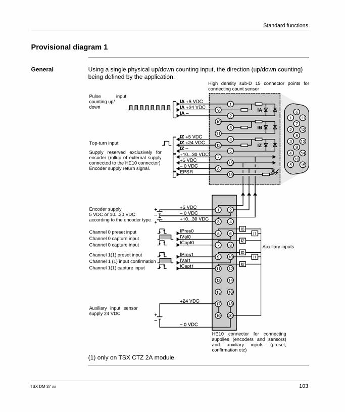
Standard functions
Provisional diagram 1
General Using a single physical up/down counting input, the direction (up/down counting) being defined by the application:
(1) only on TSX CTZ 2A module.
High density sub-D 15 connector points forconnecting count sensor
Pulse inputcounting up/down
Top-turn input
Supply reserved exclusively forencoder (rollup of external supplyconnected to the HE10 connector)Encoder supply return signal.
Encoder supply5 VDC or 10...30 VDCaccording to the encoder type
Channel 0 preset inputChannel 0 capture inputChannel 0 capture input
Channel 1(1) preset inputChannel 1 (1) input confirmationChannel 1(1) capture input
Auxiliary input sensorsupply 24 VDC
HE10 connector for connectingsupplies (encoders and sensors)and auxiliary inputs (preset,confirmation etc)
Auxiliary inputs
TSX DM 37 xx 103
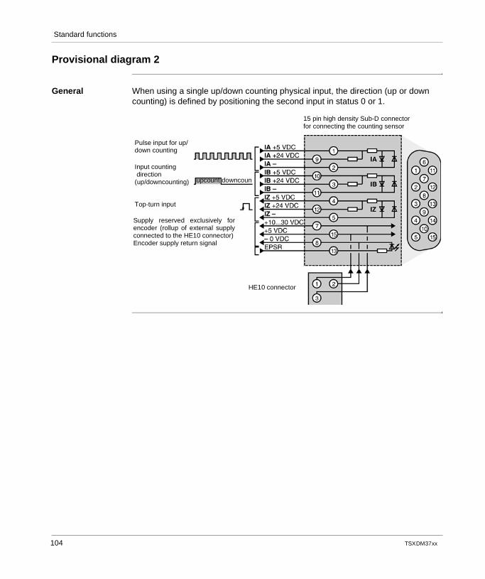
Standard functions
Provisional diagram 2
General When using a single up/down counting physical input, the direction (up or down counting) is defined by positioning the second input in status 0 or 1.
15 pin high density Sub-D connectorfor connecting the counting sensor
Pulse input for up/down counting
Input counting direction(up/downcounting)
Top-turn input
Supply reserved exclusively forencoder (rollup of external supplyconnected to the HE10 connector)Encoder supply return signal
HE10 connector
upcount downcoun
104 TSX DM 37 xx
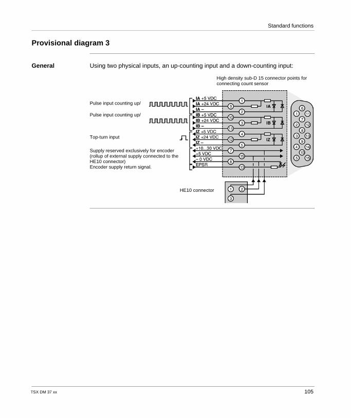
Standard functions
Provisional diagram 3
General Using two physical inputs, an up-counting input and a down-counting input:
High density sub-D 15 connector points for connecting count sensor
Pulse input counting up/
Pulse input counting up/
Top-turn input
Supply reserved exclusively for encoder (rollup of external supply connected to the HE10 connector)Encoder supply return signal.
HE10 connector
TSX DM 37 xx 105
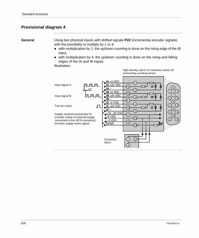
Standard functions
Provisional diagram 4
General Using two physical inputs with shifted signals Pi/2 (incremental encoder signals) with the possibility to multiply by 1 or 4: with multiplication by 1: the up/down counting is done on the rising edge of the IB
input, with multiplication by 4: the up/down counting is done on the rising and falling
edges of the IA and IB inputs.Illustration:
High density sub-D 15 connector points for connecting counting sensor
Input signal A
Input signal B
Top-turn input
Supply reserved exclusively for encoder (rollup of external supply connected to the HE10 connector)Encoder supply return signal.
Connector HE10
106 TSX DM 37 xx
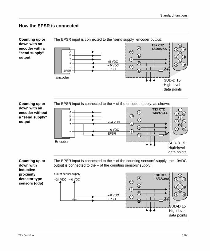
Standard functions
How the EPSR is connected
Counting up or down with an encoder with a "send supply" output
The EPSR input is connected to the "send supply" encoder output:
Counting up or down with an encoder without a "send supply" output
The EPSR input is connected to the + of the encoder supply, as shown:
Counting up or down with inductive proximity detector type sensors (ddp)
The EPSR input is connected to the + of the counting sensors’ supply; the –0VDC output is connected to the – of the counting sensors’ supply:
SUD-D 15 High-leveldata points
Encoder
SUD-D 15 High-leveldata points
Encoder
SUD-D 15 High-leveldata points
Count sensor supply
TSX DM 37 xx 107

Standard functions
108 TSX DM 37 xx
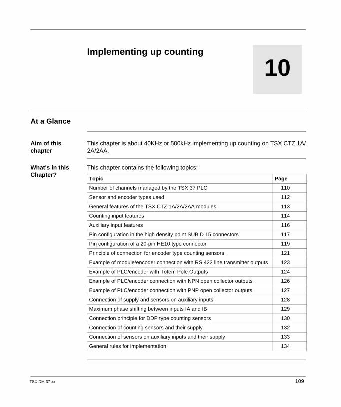
TSX DM 37 xx
10
Implementing up countingAt a Glance
Aim of this chapter
This chapter is about 40KHz or 500kHz implementing up counting on TSX CTZ 1A/2A/2AA.
What's in this Chapter?
This chapter contains the following topics:
Topic Page
Number of channels managed by the TSX 37 PLC 110
Sensor and encoder types used 112
General features of the TSX CTZ 1A/2A/2AA modules 113
Counting input features 114
Auxiliary input features 116
Pin configuration in the high density point SUB D 15 connectors 117
Pin configuration of a 20-pin HE10 type connector 119
Principle of connection for encoder type counting sensors 121
Example of module/encoder connection with RS 422 line transmitter outputs 123
Example of PLC/encoder with Totem Pole Outputs 124
Example of PLC/encoder connection with NPN open collector outputs 126
Example of PLC/encoder connection with PNP open collector outputs 127
Connection of supply and sensors on auxiliary inputs 128
Maximum phase shifting between inputs IA and IB 129
Connection principle for DDP type counting sensors 130
Connection of counting sensors and their supply 132
Connection of sensors on auxiliary inputs and their supply 133
General rules for implementation 134
109
Implementing up counting
Number of channels managed by the TSX 37 PLC
General All the TSX 37 (TSX 37 05/08/10/21/22) PLCs can manage several counting channels, and according to the TSX 37 PLC type, they can have: two 500 Hz counting channels on discrete inputs, two built-in 10 kHz counting channels, one or more counting channels on the TSX CTZ 1A/2A 40 kHz or TSX CTZ 2AA
500 kHz modules (module compatible with processors of a version above 2).
Maximum number of counting modules
The maximum number of counting modules which can be installed on a TSX 37 PLC depends on the number of channels used when counting 500 Hz and 10 kHz, not exceeding: 2 modules for a TSX 37 05/08/10 PLC, 4 modules for a TSX 37 21 or TSX 37 22 PLC.
110 TSX DM 37 xx
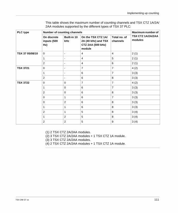
Implementing up counting
This table shows the maximum number of counting channels and TSX CTZ 1A/2A/2AA modules supported by the different types of TSX 37 PLC:
(1) 2 TSX CTZ 2A/2AA modules.(2) 3 TSX CTZ 2A/2AA modules + 1 TSX CTZ 1A module.(3) 3 TSX CTZ 2A/2AA modules.(4) 2 TSX CTZ 2A/2AA modules + 1 TSX CTZ 1A module.
PLC type Number of counting channels Maximum number of TSX CTZ 1A/2A/2AA modules
On discrete inputs (500 Hz)
Built-in 10 kHz
On the TSX CTZ 1A/2A (40 kHz) and TSX CTZ 2AA (500 kHz) module
Total no. of channels
TSX 37 05/08/10 0 - 4 4 2 (1)
1 - 4 5 2 (1)
2 - 4 6 2 (1)
TSX 3721 0 - 7 7 4 (2)
1 - 6 7 3 (3)
2 - 6 8 3 (3)
TSX 3722 0 0 7 7 4 (2)
1 0 6 7 3 (3)
2 0 6 8 3 (3)
0 1 6 7 3 (3)
0 2 6 8 3 (3)
1 1 6 8 3 (3)
2 1 5 8 3 (4)
1 2 5 8 3 (4)
2 2 5 9 3 (4)
TSX DM 37 xx 111
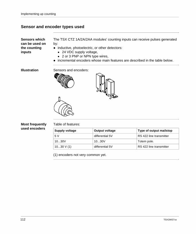
Implementing up counting
Sensor and encoder types used
Sensors which can be used on the counting inputs
The TSX CTZ 1A/2A/2AA modules’ counting inputs can receive pulses generated by: inductive, photoelectric, or other detectors:
24 VDC supply voltage, 2 or 3 PNP or NPN type wires,
incremental encoders whose main features are described in the table below.
Illustration Sensors and encoders:
Most frequently used encoders
Table of features:
(1) encoders not very common yet.
Supply voltage Output voltage Type of output mailstop
5 V differential 5V RS 422 line transmitter
10...30V 10...30V Totem pole.
10...30 V (1) differential 5V RS 422 line transmitter
112 TSX DM 37 xx
Implementing up counting
General features of the TSX CTZ 1A/2A/2AA modules
Table of features This chapter introduces the different features of the TSX CTZ 1A/2A/2AA modules.
Modules TSX CTZ 1A TSX CTZ 2A TSX CTZ 2AA
Maximum frequency on the counting inputs
40 kHz 40 kHz 500 kHz
Current used by the module
on the internal 5V 100 mA 120 mA 120 mA
on the internal 24 15 mA 15 mA 15 mA
Power dispersed in the module 2.6 W 4.5 W 4.5 W
Sensor supply check Yes Yes Yes
Operational temperature 0 to 60°C 0 to 60°C 0 to 60°C
Input/ground or input and internal logic dielectric strength
1000 V effective – 50/60 Hz – 1 mn
Insulation resistance > 10 MΩ under 500 VDC
Hygrometry 5% to 95% without condensation
Storage temperature -25° to +70°C
Operational altitude 0 to 2000 meters
TSX DM 37 xx 113
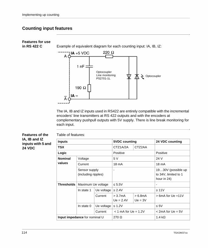
Implementing up counting
Counting input features
Features for use in RS 422 C Example of equivalent diagram for each counting input: IA, IB, IZ:
The IA, IB and IZ inputs used in RS422 are entirely compatible with the incremental encoders’ line transmitters at RS 422 outputs and with the encoders at complementary pushpull outputs with 5V supply. There is line break monitoring for each input.
Features of the IA, IB and IZ inputs with 5 and 24 VDC
Table of features:
OptocouplerLine monitoringPS2701-1L
Optocoupler
Inputs 5VDC counting 24 VDC counting
TSX CTZ1A/2A CTZ2AA
Logic Positive Positive
Nominal values
Voltage 5 V 24 V
Current 18 mA 18 mA
Sensor supply(including ripples)
- 19…30V (possible up to 34V, limited to 1 hour in 24)
Thresholds Maximum Ue voltage ≤ 5.5V -
In state 1 Ue voltage ≥ 2.4V ≥ 11V
Current > 3.7mAUe = 2.4V
> 6.8mAUe = 3V
> 6mA for Ue =11V
In state 0 Ue voltage ≤ 1.2V ≤ 5V
Current < 1 mA for Ue = 1.2V < 2mA for Ue = 5V
Input impedance for nominal U 270 Ω 1.4 kΩ
114 TSX DM 37 xx
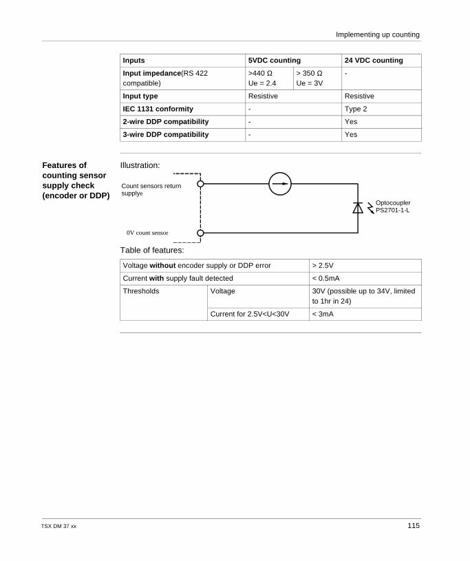
Implementing up counting
Features of counting sensor supply check (encoder or DDP)
Illustration:
Table of features:
Input impedance(RS 422 compatible)
>440 ΩUe = 2.4
> 350 ΩUe = 3V
-
Input type Resistive Resistive
IEC 1131 conformity - Type 2
2-wire DDP compatibility - Yes
3-wire DDP compatibility - Yes
Inputs 5VDC counting 24 VDC counting
Voltage without encoder supply or DDP error > 2.5V
Current with supply fault detected < 0.5mA
Thresholds Voltage 30V (possible up to 34V, limited to 1hr in 24)
Current for 2.5V<U<30V < 3mA
Count sensors return supplye
0V count sensor
OptocouplerPS2701-1-L
TSX DM 37 xx 115
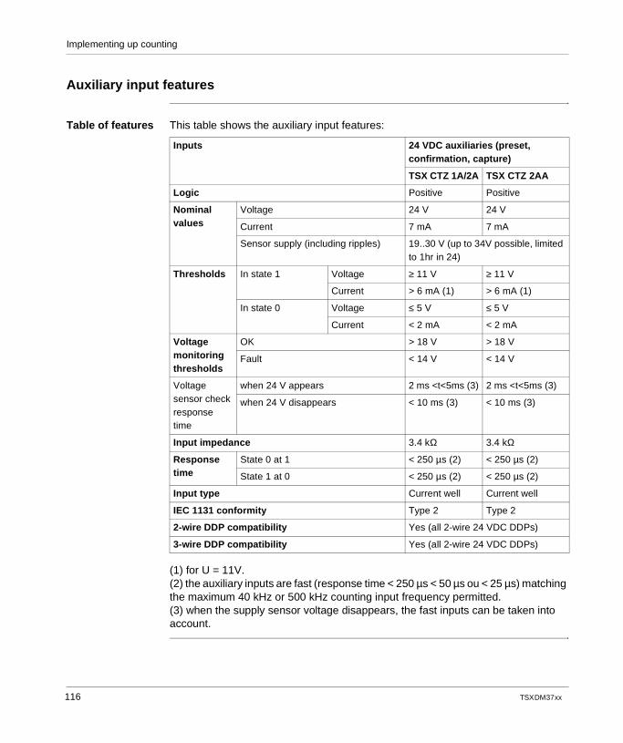
Implementing up counting
Auxiliary input features
Table of features This table shows the auxiliary input features:
(1) for U = 11V.(2) the auxiliary inputs are fast (response time < 250 µs < 50 µs ou < 25 µs) matching the maximum 40 kHz or 500 kHz counting input frequency permitted.(3) when the supply sensor voltage disappears, the fast inputs can be taken into account.
Inputs 24 VDC auxiliaries (preset, confirmation, capture)
TSX CTZ 1A/2A TSX CTZ 2AA
Logic Positive Positive
Nominal values
Voltage 24 V 24 V
Current 7 mA 7 mA
Sensor supply (including ripples) 19..30 V (up to 34V possible, limited to 1hr in 24)
Thresholds In state 1 Voltage ≥ 11 V ≥ 11 V
Current > 6 mA (1) > 6 mA (1)
In state 0 Voltage ≤ 5 V ≤ 5 V
Current < 2 mA < 2 mA
Voltage monitoring thresholds
OK > 18 V > 18 V
Fault < 14 V < 14 V
Voltage sensor check response time
when 24 V appears 2 ms <t<5ms (3) 2 ms <t<5ms (3)
when 24 V disappears < 10 ms (3) < 10 ms (3)
Input impedance 3.4 kΩ 3.4 kΩ
Response time
State 0 at 1 < 250 µs (2) < 250 µs (2)
State 1 at 0 < 250 µs (2) < 250 µs (2)
Input type Current well Current well
IEC 1131 conformity Type 2 Type 2
2-wire DDP compatibility Yes (all 2-wire 24 VDC DDPs)
3-wire DDP compatibility Yes (all 2-wire 24 VDC DDPs)
116 TSX DM 37 xx
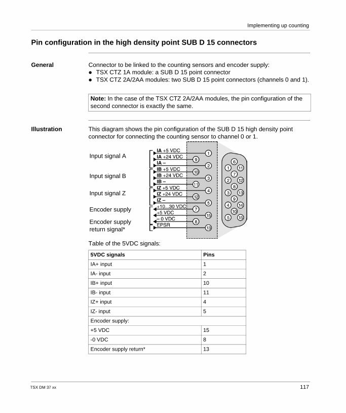
Implementing up counting
Pin configuration in the high density point SUB D 15 connectors
General Connector to be linked to the counting sensors and encoder supply: TSX CTZ 1A module: a SUB D 15 point connector TSX CTZ 2A/2AA modules: two SUB D 15 point connectors (channels 0 and 1).
Illustration This diagram shows the pin configuration of the SUB D 15 high density point connector for connecting the counting sensor to channel 0 or 1.
Table of the 5VDC signals:
Note: In the case of the TSX CTZ 2A/2AA modules, the pin configuration of the second connector is exactly the same.
5VDC signals Pins
IA+ input 1
IA- input 2
IB+ input 10
IB- input 11
IZ+ input 4
IZ- input 5
Encoder supply:
+5 VDC 15
-0 VDC 8
Encoder supply return* 13
Input signal A
Input signal B
Input signal Z
Encoder supply
Encoder supply return signal*
TSX DM 37 xx 117
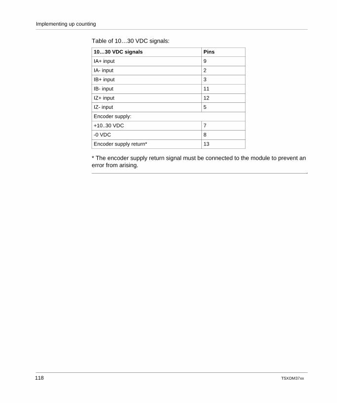
Implementing up counting
Table of 10…30 VDC signals:
* The encoder supply return signal must be connected to the module to prevent an error from arising.
10…30 VDC signals Pins
IA+ input 9
IA- input 2
IB+ input 3
IB- input 11
IZ+ input 12
IZ- input 5
Encoder supply:
+10..30 VDC 7
-0 VDC 8
Encoder supply return* 13
118 TSX DM 37 xx
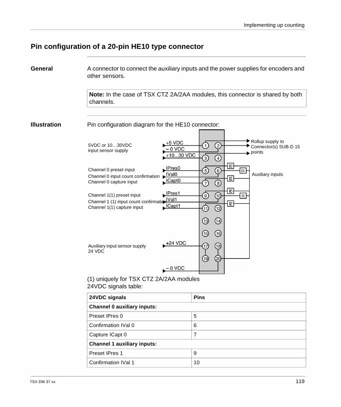
Implementing up counting
Pin configuration of a 20-pin HE10 type connector
General A connector to connect the auxiliary inputs and the power supplies for encoders and other sensors.
Illustration Pin configuration diagram for the HE10 connector:
(1) uniquely for TSX CTZ 2A/2AA modules24VDC signals table:
Note: In the case of TSX CTZ 2A/2AA modules, this connector is shared by both channels.
24VDC signals Pins
Channel 0 auxiliary inputs:
Preset IPres 0 5
Confirmation IVal 0 6
Capture ICapt 0 7
Channel 1 auxiliary inputs:
Preset IPres 1 9
Confirmation IVal 1 10
Rollup supply toConnector(s) SUB-D 15 points
Auxiliary inputs
5VDC or 10…30VDC input sensor supply
Channel 0 preset inputChannel 0 input count confirmationChannel 0 capture input
Channel 1(1) preset inputChannel 1 (1) input count confirmationChannel 1(1) capture input
Auxiliary input sensor supply24 VDC
TSX DM 37 xx 119
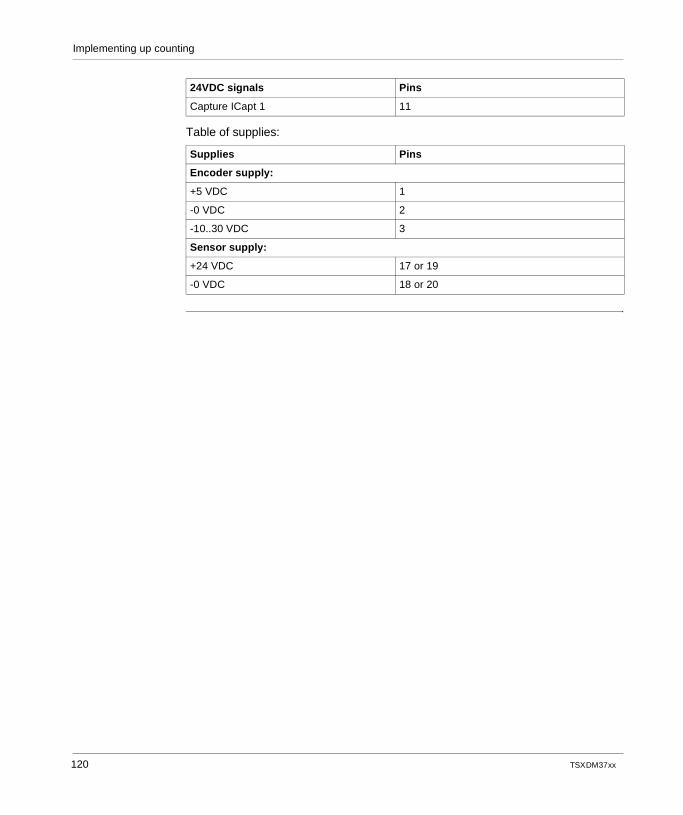
Implementing up counting
Table of supplies:
Capture ICapt 1 11
Supplies Pins
Encoder supply:
+5 VDC 1
-0 VDC 2
-10..30 VDC 3
Sensor supply:
+24 VDC 17 or 19
-0 VDC 18 or 20
24VDC signals Pins
120 TSX DM 37 xx
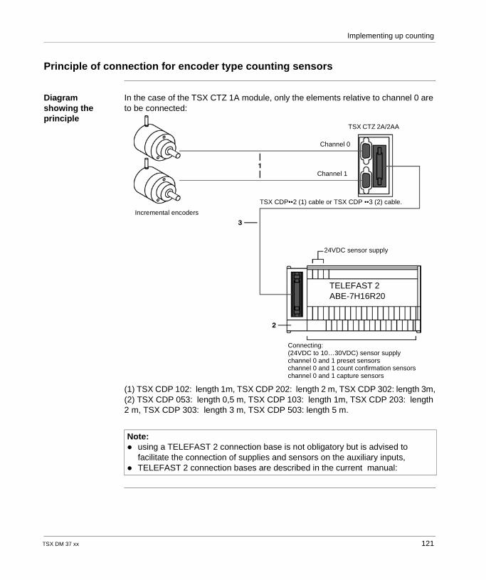
Implementing up counting
Principle of connection for encoder type counting sensors
Diagram showing the principle
In the case of the TSX CTZ 1A module, only the elements relative to channel 0 are to be connected:
(1) TSX CDP 102: length 1m, TSX CDP 202: length 2 m, TSX CDP 302: length 3m,(2) TSX CDP 053: length 0,5 m, TSX CDP 103: length 1m, TSX CDP 203: length 2 m, TSX CDP 303: length 3 m, TSX CDP 503: length 5 m.
Note: using a TELEFAST 2 connection base is not obligatory but is advised to
facilitate the connection of supplies and sensors on the auxiliary inputs, TELEFAST 2 connection bases are described in the current manual:
TSX CTZ 2A/2AA
Channel 0
Channel 1
TSX CDP••2 (1) cable or TSX CDP ••3 (2) cable.
Incremental encoders
24VDC sensor supply
TELEFAST 2ABE-7H16R20
Connecting:(24VDC to 10…30VDC) sensor supplychannel 0 and 1 preset sensorschannel 0 and 1 count confirmation sensorschannel 0 and 1 capture sensors
TSX DM 37 xx 121

Implementing up counting
Description of the different connection elements
1 Connection of an encoder to the high density 15-pin SUB-D connector found on the TSX CTZ 1A/2A/2AA modules. Taking into account the different encoder types, this connection is your responsibility and is made up of: a connector to be connected to the encoder (generally a 12-pin female DIN
connector, but to be defined according to the encoder connection used), a high density 15-pin SUB-D male connector to connect to the 15-pin SUB-D
female connector of the TSX CTZ 1A/2A/2AA modules. A component provided separately under the reference TSX CAP H15,
a cable:- with twisted pairs(gage 26) and shielding for an encoder with RS 422 standard line sender outputs,- multi-conductors (gauge 24) with shielding for an encoder with Totem Pole outputs.The cable shielding will be "tress and steel strip"; the "tress and steel strip" contact with each connector’s ground must be ensured by tightening across the whole diameter of the cable.The connection of this cable to these two connectors varies according to the encoder supply type (5 VDC or 10…30 VDC) and the output type (RS 422, Totem Pole). For example, some connection types are described in the present chapter.
2 TELEFAST 2 connection base: ABE-7H08R10 or ABE-7H16R20.This base is used for a quick connection of: the 24 VDC supply for sensors other than the encoder, the encoder supply the sensors on the auxiliary inputs (preset, confirmation, capture).Type of base to use according to the counting module: TSX CTZ 1A module: use the reference ABE-7H8R10 or ABE-7H16R20, TSX CTZ 2A module: use the reference ABE-7H16R20, TSX CTZ 2AA module: use the reference ABE-7H16R20.
3 TSX CDP••3 connection cable or a TSX CDP••2 multi-stranded sheathed cable.
122 TSX DM 37 xx
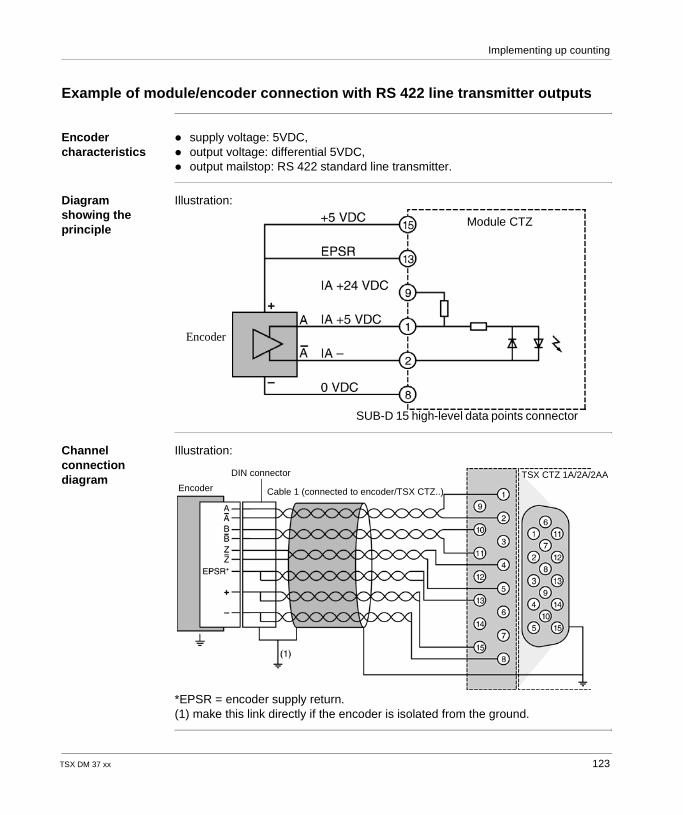
Implementing up counting
Example of module/encoder connection with RS 422 line transmitter outputs
Encoder characteristics
supply voltage: 5VDC, output voltage: differential 5VDC, output mailstop: RS 422 standard line transmitter.
Diagram showing the principle
Illustration:
Channel connection diagram
Illustration:
*EPSR = encoder supply return.(1) make this link directly if the encoder is isolated from the ground.
SUB-D 15 high-level data points connector
Encoder
Module CTZ
TSX CTZ 1A/2A/2AAEncoder
DIN connector
Cable 1 (connected to encoder/TSX CTZ..)
TSX DM 37 xx 123
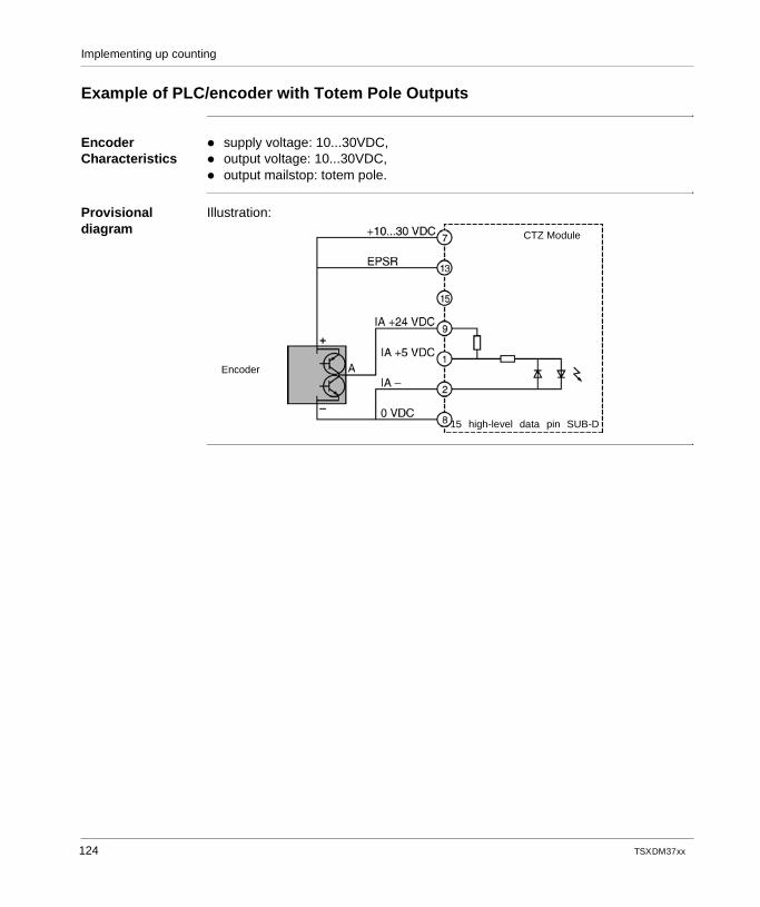
Implementing up counting
Example of PLC/encoder with Totem Pole Outputs
Encoder Characteristics
supply voltage: 10...30VDC, output voltage: 10...30VDC, output mailstop: totem pole.
Provisional diagram
Illustration:
Encoder
15 high-level data pin SUB-D
CTZ Module
124 TSX DM 37 xx
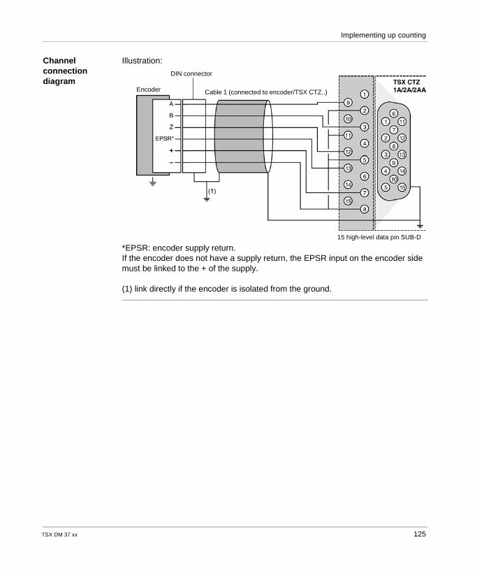
Implementing up counting
Channel connection diagram
Illustration:
*EPSR: encoder supply return.If the encoder does not have a supply return, the EPSR input on the encoder side must be linked to the + of the supply.
(1) link directly if the encoder is isolated from the ground.
Encoder
DIN connector
Cable 1 (connected to encoder/TSX CTZ..)
15 high-level data pin SUB-D
TSX DM 37 xx 125
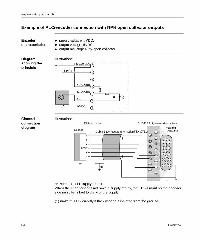
Implementing up counting
Example of PLC/encoder connection with NPN open collector outputs
Encoder characteristics
supply voltage: 5VDC, output voltage: 5VDC, output mailstop: NPN open collector.
Diagram showing the principle
Illustration:
Channel connection diagram
Illustration:
*EPSR: encoder supply return.When the encoder does not have a supply return, the EPSR input on the encoder side must be linked to the + of the supply.
(1) make this link directly if the encoder is isolated from the ground.
SUB-D 15 high-level data pointsDIN connector
EncoderCable 1 (connected to encoder/TSX CTZ..)
126 TSX DM 37 xx
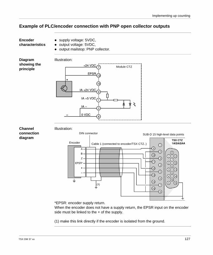
Implementing up counting
Example of PLC/encoder connection with PNP open collector outputs
Encoder characteristics
supply voltage: 5VDC, output voltage: 5VDC, output mailstop: PNP collector.
Diagram showing the principle
Illustration:
Channel connection diagram
Illustration:
*EPSR: encoder supply return.When the encoder does not have a supply return, the EPSR input on the encoder side must be linked to the + of the supply.
(1) make this link directly if the encoder is isolated from the ground.
Module CTZ
SUB-D 15 high-level data pointsDIN connector
Encoder Cable 1 (connected to encoder/TSX CTZ..)
TSX DM 37 xx 127
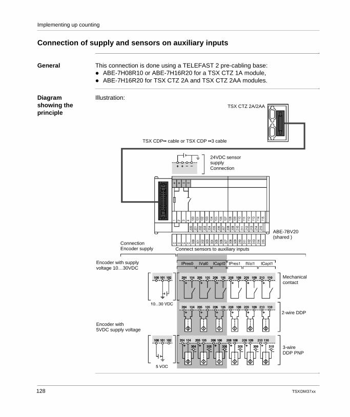
Implementing up counting
Connection of supply and sensors on auxiliary inputs
General This connection is done using a TELEFAST 2 pre-cabling base: ABE-7H08R10 or ABE-7H16R20 for a TSX CTZ 1A module, ABE-7H16R20 for TSX CTZ 2A and TSX CTZ 2AA modules.
Diagram showing the principle
Illustration:
TSX CDP•• cable or TSX CDP ••3 cable
TSX CTZ 2A/2AA
ConnectionEncoder supply Connect sensors to auxiliary inputs
ABE-7BV20(shared )
Encoder with supplyvoltage 10…30VDC
Encoder with 5VDC supply voltage
Mechanical contact
2-wire DDP
3-wireDDP PNP
24VDC sensor supplyConnection
128 TSX DM 37 xx
Implementing up counting
Maximum phase shifting between inputs IA and IB
General An incremental encoder connected to a TSX CTZ 1A/2A/2AA module gives counting pulses which are separated by 90°.The module input signals are not rigorously separated by 90° according to the length of the connection cables. The maximum separation limits allowed between signals IA and IB are +/- 45°.
TSX DM 37 xx 129
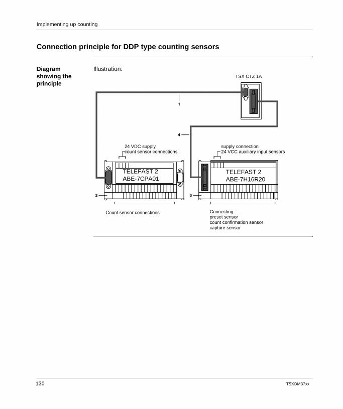
Implementing up counting
Connection principle for DDP type counting sensors
Diagram showing the principle
Illustration: TSX CTZ 1A
24 VDC supplycount sensor connections
supply connection24 VCC auxiliary input sensors
TELEFAST 2ABE-7CPA01
TELEFAST 2ABE-7H16R20
Count sensor connections Connecting:preset sensorcount confirmation sensorcapture sensor
130 TSX DM 37 xx
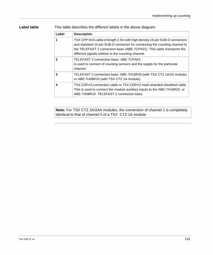
Implementing up counting
Label table This table describes the different labels in the above diagram:
Label Description
1 TSX CPP H15 cable of length 2.5m with high density 15-pin SUB-D connectors and standard 15-pin SUB-D connector for connecting the counting channel to the TELEFAST 2 connection base (ABE-7CPA01). This cable transports the different signals relative to the counting channel.
2 TELEFAST 2 connection base: ABE-7CPA01:is used to connect of counting sensors and the supply for the particular channel.
3 TELEFAST 2 connection base: ABE-7H16R20 (with TSX CTZ 1A/2A module) or ABE-7H08R10 (with TSX CTZ 1A module).
4 TSX CDP••3 connection cable or TSX CDP••2 multi-stranded sheathed cable. This is used to connect the module auxiliary inputs to the ABE-7H16R20. or ABE-7H08R10. TELEFAST 2 connection base.
Note: For TSX CTZ 2A/2AA modules, the connection of channel 1 is completely identical to that of channel 0 of a TSX CTZ 1A module.
TSX DM 37 xx 131
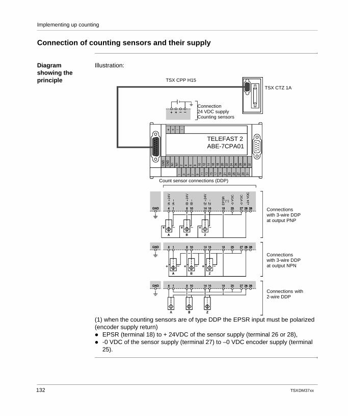
Implementing up counting
Connection of counting sensors and their supply
Diagram showing the principle
Illustration:
(1) when the counting sensors are of type DDP the EPSR input must be polarized (encoder supply return) EPSR (terminal 18) to + 24VDC of the sensor supply (terminal 26 or 28), -0 VDC of the sensor supply (terminal 27) to –0 VDC encoder supply (terminal
25).
TSX CPP H15
TSX CTZ 1A
Connection24 VDC supplyCounting sensors
TELEFAST 2ABE-7CPA01
Count sensor connections (DDP)
Connectionswith 3-wire DDP at output PNP
Connectionswith 3-wire DDP at output NPN
Connections with2-wire DDP
132 TSX DM 37 xx
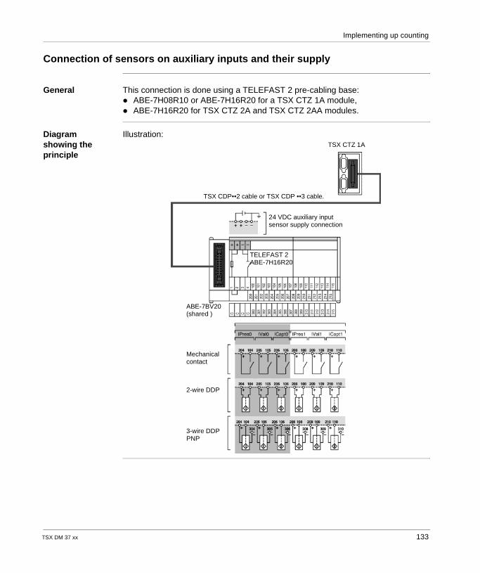
Implementing up counting
Connection of sensors on auxiliary inputs and their supply
General This connection is done using a TELEFAST 2 pre-cabling base: ABE-7H08R10 or ABE-7H16R20 for a TSX CTZ 1A module, ABE-7H16R20 for TSX CTZ 2A and TSX CTZ 2AA modules.
Diagram showing the principle
Illustration: TSX CTZ 1A
TSX CDP••2 cable or TSX CDP ••3 cable.
TELEFAST 2ABE-7H16R20
ABE-7BV20(shared )
Mechanical contact
2-wire DDP
3-wire DDPPNP
24 VDC auxiliary inputsensor supply connection
TSX DM 37 xx 133
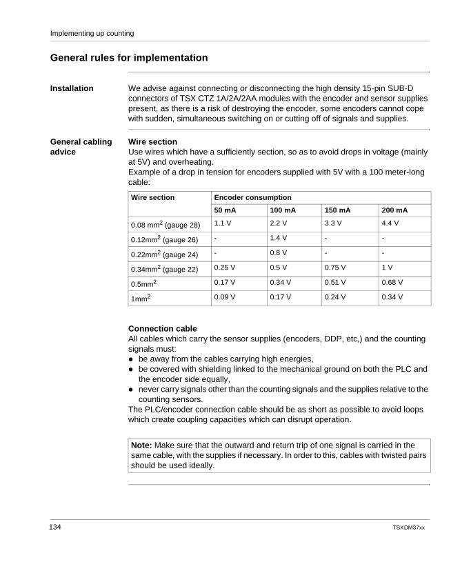
Implementing up counting
General rules for implementation
Installation We advise against connecting or disconnecting the high density 15-pin SUB-D connectors of TSX CTZ 1A/2A/2AA modules with the encoder and sensor supplies present, as there is a risk of destroying the encoder, some encoders cannot cope with sudden, simultaneous switching on or cutting off of signals and supplies.
General cabling advice
Wire sectionUse wires which have a sufficiently section, so as to avoid drops in voltage (mainly at 5V) and overheating.Example of a drop in tension for encoders supplied with 5V with a 100 meter-long cable:
Connection cableAll cables which carry the sensor supplies (encoders, DDP, etc,) and the counting signals must: be away from the cables carrying high energies, be covered with shielding linked to the mechanical ground on both the PLC and
the encoder side equally, never carry signals other than the counting signals and the supplies relative to the
counting sensors.The PLC/encoder connection cable should be as short as possible to avoid loops which create coupling capacities which can disrupt operation.
Wire section Encoder consumption
50 mA 100 mA 150 mA 200 mA
0.08 mm2 (gauge 28) 1.1 V 2.2 V 3.3 V 4.4 V
0.12mm2 (gauge 26) - 1.4 V - -
0.22mm2 (gauge 24) - 0.8 V - -
0.34mm2 (gauge 22) 0.25 V 0.5 V 0.75 V 1 V
0.5mm2 0.17 V 0.34 V 0.51 V 0.68 V
1mm2 0.09 V 0.17 V 0.24 V 0.34 V
Note: Make sure that the outward and return trip of one signal is carried in the same cable, with the supplies if necessary. In order to this, cables with twisted pairs should be used ideally.
134 TSX DM 37 xx
Implementing up counting
Encoder and auxiliary sensor supply
Encoder supplyThe encoder must: be reserved exclusively for supplying the encoder, to cut off parasitic pulses
which could disrupt the encoders which contain sensitive electronics, be placed as near as possible to the TELEFAST 2 base to reduce drops in
voltage and couplings with other cables, be protected against short-circuits and overloading by fast-blow fuses, have a good level of endurance to be able to cut off micro outages.
ImportantThe polarity – 0VDC of encoder and auxiliary sensor supplies must be grounded as close to the supplies as possible.The cables carrying supply voltages should have their shielding grounded.
TSX DM 37 xx 135

Implementing up counting
136 TSX DM 37 xx
TSX DM 37 xx
11
TELEFAST 2 connection base: ABE-7CPA01At a Glance
Aim of this chapter
This chapter aims to introduce the TELEFAST 2 connection base: ABE-7CPA01.
What's in this Chapter?
This chapter contains the following topics:
Topic Page
Introduction 138
Cabling layout 139
Construction and mounting 140
Availability of the counting signals on the TELEFAST screw terminal block 141
Matching TELEFAST terminal blocks and 15-pin SUB-D connector 142
137
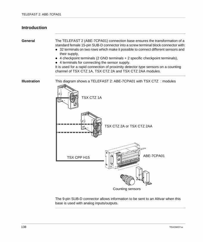
TELEFAST 2: ABE-7CPA01
Introduction
General The TELEFAST 2 (ABE-7CPA01) connection base ensures the transformation of a standard female 15-pin SUB-D connector into a screw terminal block connector with: 32 terminals on two rows which make it possible to connect different sensors and
their supply, 4 checkpoint terminals (2 GND terminals + 2 specific checkpoint terminals), 4 terminals for connecting the sensor supply.It is used for a rapid connection of proximity detector type sensors on a counting channel of TSX CTZ 1A, TSX CTZ 2A and TSX CTZ 2AA modules.
Illustration This diagram shows a TELEFAST 2: ABE-7CPA01 with TSX CTZ : modules
The 9-pin SUB-D connector allows information to be sent to an Altivar when this base is used with analog inputs/outputs.
TSX CTZ 1A
TSX CTZ 2A or TSX CTZ 2AA
TSX CPP H15
Counting sensors
ABE-7CPA01
138 TSX DM 37 xx
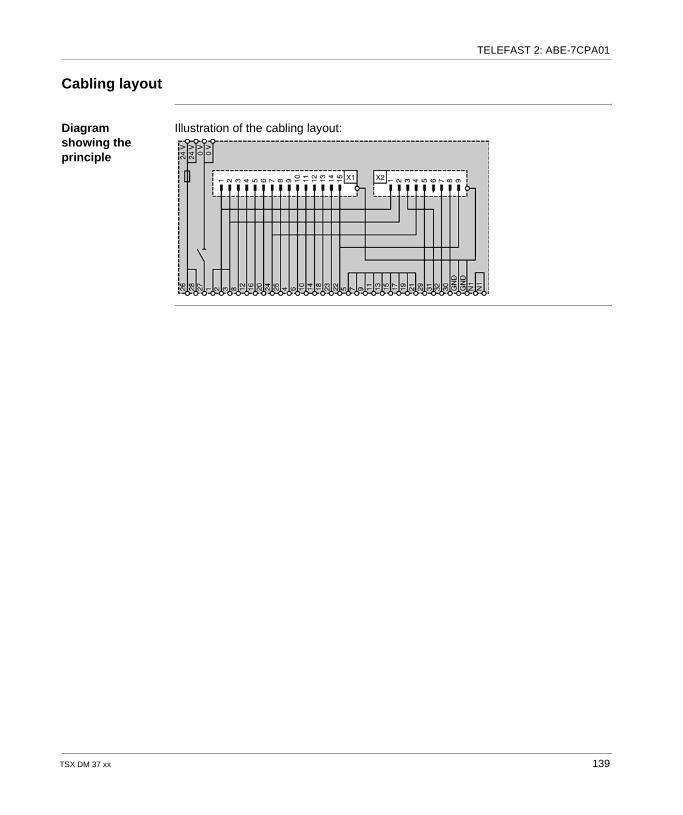
TELEFAST 2: ABE-7CPA01
Cabling layout
Diagram showing the principle
Illustration of the cabling layout:
TSX DM 37 xx 139
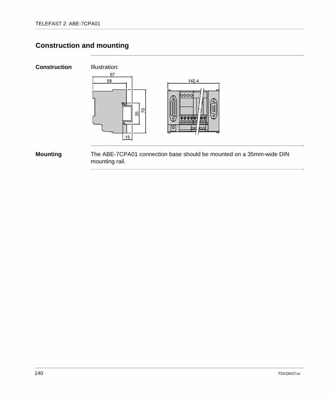
TELEFAST 2: ABE-7CPA01
Construction and mounting
Construction Illustration:
Mounting The ABE-7CPA01 connection base should be mounted on a 35mm-wide DIN mounting rail.
140 TSX DM 37 xx
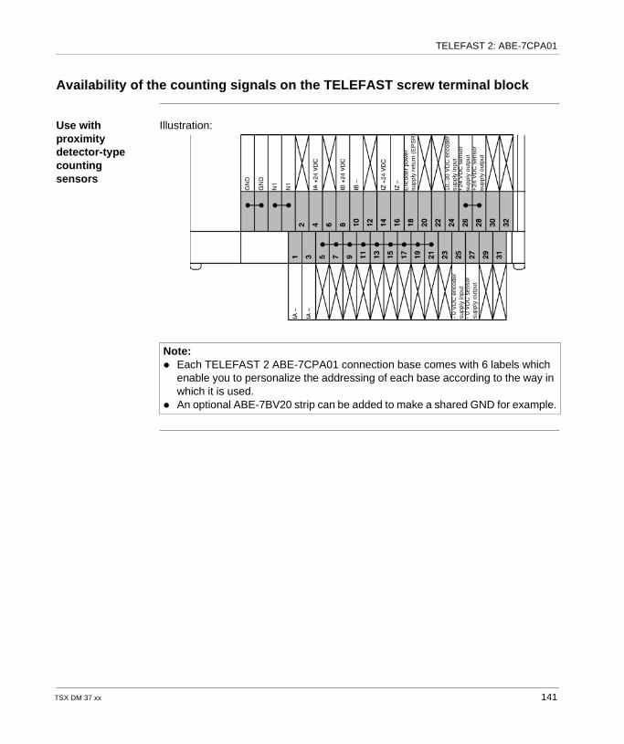
TELEFAST 2: ABE-7CPA01
Availability of the counting signals on the TELEFAST screw terminal block
Use with proximity detector-type counting sensors
Illustration:
Note: Each TELEFAST 2 ABE-7CPA01 connection base comes with 6 labels which
enable you to personalize the addressing of each base according to the way in which it is used.
An optional ABE-7BV20 strip can be added to make a shared GND for example.
- 0
VD
C e
ncod
ersu
pply
inp
ut-
0 V
DC
sen
sor
supp
ly o
utpu
t
Enc
oder
pow
ersu
ppl
y re
turn
(E
PS
R)
+24
VD
C s
enso
rsu
pply
out
put
+24
VD
C s
enso
rsu
pply
out
put
10.
.30
VD
C e
ncod
ersu
ppl
y in
put
TSX DM 37 xx 141
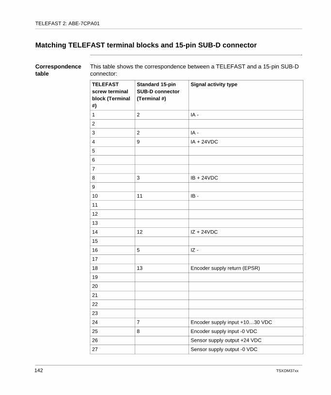
TELEFAST 2: ABE-7CPA01
Matching TELEFAST terminal blocks and 15-pin SUB-D connector
Correspondence table
This table shows the correspondence between a TELEFAST and a 15-pin SUB-D connector:
TELEFAST screw terminal block (Terminal #)
Standard 15-pin SUB-D connector (Terminal #)
Signal activity type
1 2 IA -
2
3 2 IA -
4 9 IA + 24VDC
5
6
7
8 3 IB + 24VDC
9
10 11 IB -
11
12
13
14 12 IZ + 24VDC
15
16 5 IZ -
17
18 13 Encoder supply return (EPSR)
19
20
21
22
23
24 7 Encoder supply input +10…30 VDC
25 8 Encoder supply input -0 VDC
26 Sensor supply output +24 VDC
27 Sensor supply output -0 VDC
142 TSX DM 37 xx
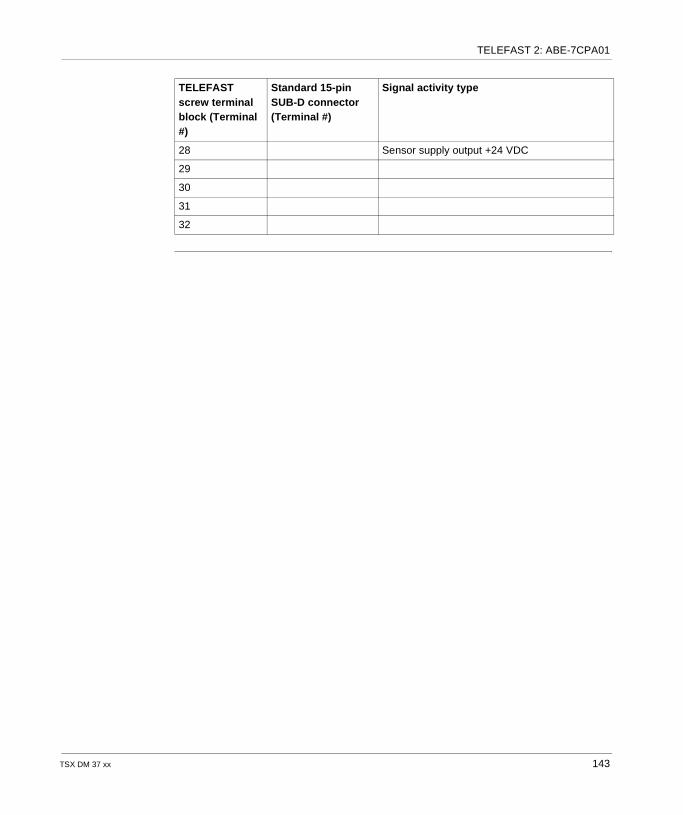
TELEFAST 2: ABE-7CPA01
28 Sensor supply output +24 VDC
29
30
31
32
TELEFAST screw terminal block (Terminal #)
Standard 15-pin SUB-D connector (Terminal #)
Signal activity type
TSX DM 37 xx 143

TELEFAST 2: ABE-7CPA01
144 TSX DM 37 xx
TSX DM 37 xx
12
TELEFAST 2 connection base: ABE-7H08R10/7H16R20At a Glance
Aim of this chapter
This chapter aims to introduce the TELEFAST 2 connection base: ABE-7H08R10/7H16R20.
What's in this Chapter?
This chapter contains the following topics:
Topic Page
At a Glance 146
Availability of the signals on the TELEFAST screw terminal block 147
Correspondences between TELEFAST terminal blocks and HE10 connector 148
145
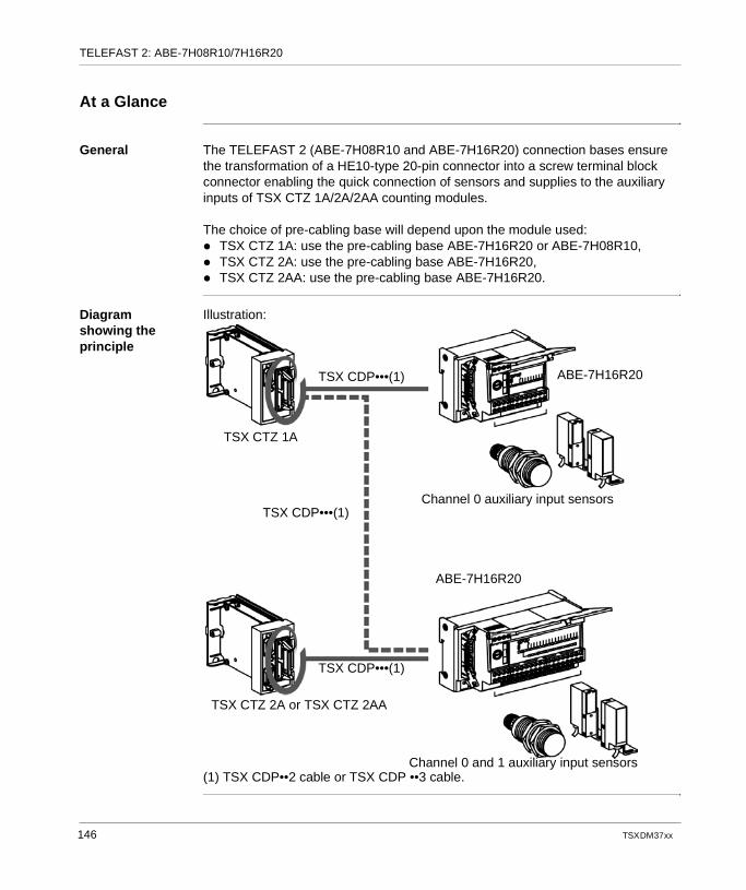
TELEFAST 2: ABE-7H08R10/7H16R20
At a Glance
General The TELEFAST 2 (ABE-7H08R10 and ABE-7H16R20) connection bases ensure the transformation of a HE10-type 20-pin connector into a screw terminal block connector enabling the quick connection of sensors and supplies to the auxiliary inputs of TSX CTZ 1A/2A/2AA counting modules.
The choice of pre-cabling base will depend upon the module used: TSX CTZ 1A: use the pre-cabling base ABE-7H16R20 or ABE-7H08R10, TSX CTZ 2A: use the pre-cabling base ABE-7H16R20, TSX CTZ 2AA: use the pre-cabling base ABE-7H16R20.
Diagram showing the principle
Illustration:
(1) TSX CDP••2 cable or TSX CDP ••3 cable.
TSX CDP•••(1)
TSX CDP•••(1)
TSX CDP•••(1)
TSX CTZ 1A
TSX CTZ 2A or TSX CTZ 2AA
Channel 0 and 1 auxiliary input sensors
ABE-7H16R20
Channel 0 auxiliary input sensors
ABE-7H16R20
146 TSX DM 37 xx
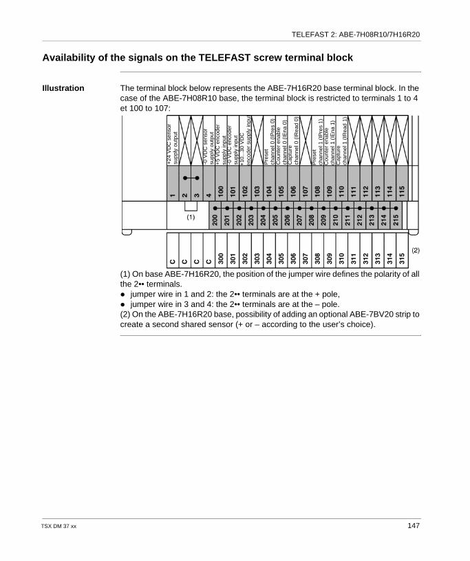
TELEFAST 2: ABE-7H08R10/7H16R20
Availability of the signals on the TELEFAST screw terminal block
Illustration The terminal block below represents the ABE-7H16R20 base terminal block. In the case of the ABE-7H08R10 base, the terminal block is restricted to terminals 1 to 4 et 100 to 107:
(1) On base ABE-7H16R20, the position of the jumper wire defines the polarity of all the 2•• terminals. jumper wire in 1 and 2: the 2•• terminals are at the + pole, jumper wire in 3 and 4: the 2•• terminals are at the – pole.(2) On the ABE-7H16R20 base, possibility of adding an optional ABE-7BV20 strip to create a second shared sensor (+ or – according to the user’s choice).
+24
VD
C s
enso
rsu
pply
out
put
-0 V
DC
sen
sor
supp
ly o
utpu
t+
5 V
DC
enc
oder
supp
ly in
put
-0 V
DC
enc
oder
supp
ly in
put
+10
...30
VD
Cen
code
r su
pply
inpu
t
Pre
set
chan
nel 0
(IP
res
0)C
ount
er e
nabl
ech
anne
l 0 (
IEna
0)
Cap
ture
chan
nel 0
(IR
ead
0)
Pre
set
chan
nel 1
(IP
res
1)C
ount
er e
nabl
ech
anne
l 1 (
IEna
1)
Cap
ture
chan
nel 1
(IR
ead
1)
TSX DM 37 xx 147
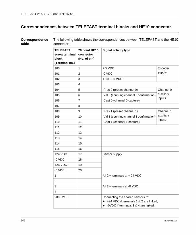
TELEFAST 2: ABE-7H08R10/7H16R20
Correspondences between TELEFAST terminal blocks and HE10 connector
Correspondence table
The following table shows the correspondences between TELEFAST and the HE10 connector:
TELEFAST screw terminal block (Terminal no.)
20 point HE10 connector(No. of pin)
Signal activity type
100 1 + 5 VDC Encoder supply101 2 -0 VDC
102 3 + 10…30 VDC
103 4
104 5 IPres 0 (preset channel 0) Channel 0 auxiliary inputs
105 6 IVal 0 (counting channel 0 confirmation)
106 7 ICapt 0 (channel 0 capture)
107 8
108 9 IPres 1 (preset channel 1) Channel 1 auxiliary inputs
109 10 IVal 1 (counting channel 1 confirmation)
110 11 ICapt 1 (channel 1 capture)
111 12
112 13
113 14
114 15
115 16
+24 VDC 17 Sensor supply
-0 VDC 18
+24 VDC 19
-0 VDC 20
1 All 2•• terminals at + 24 VDC
2
3 All 2•• terminals at -0 VDC
4
200...215 Connecting the shared sensors to: +24 VDC if terminals 1 & 2 are linked, -0VDC if terminals 3 & 4 are linked.
148 TSX DM 37 xx
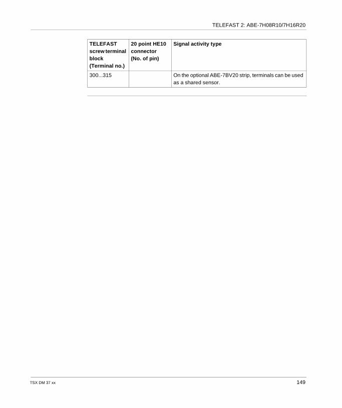
TELEFAST 2: ABE-7H08R10/7H16R20
300...315 On the optional ABE-7BV20 strip, terminals can be used as a shared sensor.
TELEFAST screw terminal block (Terminal no.)
20 point HE10 connector(No. of pin)
Signal activity type
TSX DM 37 xx 149

TELEFAST 2: ABE-7H08R10/7H16R20
150 TSX DM 37 xx
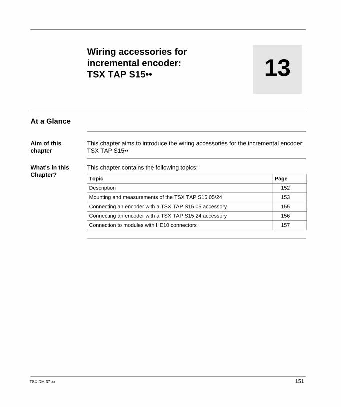
TSX DM 37 xx
13
Wiring accessories for incremental encoder: TSX TAP S15••At a Glance
Aim of this chapter
This chapter aims to introduce the wiring accessories for the incremental encoder: TSX TAP S15••
What's in this Chapter?
This chapter contains the following topics:
Topic Page
Description 152
Mounting and measurements of the TSX TAP S15 05/24 153
Connecting an encoder with a TSX TAP S15 05 accessory 155
Connecting an encoder with a TSX TAP S15 24 accessory 156
Connection to modules with HE10 connectors 157
151
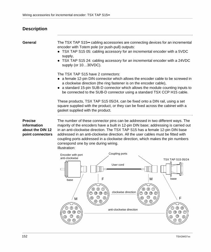
Wiring accessories for incremental encoder: TSX TAP S15••
Description
General The TSX TAP S15•• cabling accessories are connecting devices for an incremental encoder with Totem pole (or push-pull) outputs: TSX TAP S15 05: cabling accessory for an incremental encoder with a 5VDC
supply, TSX TAP S15 24: cabling accessory for an incremental encoder with a 24VDC
supply (or 10…30VDC).
The TSX TAP S15 have 2 connectors: a female 12-pin DIN connector which allows the encoder cable to be screwed in
a clockwise direction (the ring fastener is on the encoder cable), a standard 15-pin SUB-D connector which allows the module counting inputs to
be connected to the SUB-D connector using a standard TSX CCP H15 cable.
These products, TSX TAP S15 05/24, can be fixed onto a DIN rail, using a set square supplied with the product, or they can be fixed across the cabinet with a gasket supplied with the product.
Precise information about the DIN 12 point connectors
The number of these connector pins can be addressed in two different ways. The majority of the encoders have a built in 12-pin DIN base; addressing is carried out in an anti-clockwise direction. The TSX TAP S15 has a female 12-pin DIN base addressed in an anti-clockwise direction. All the user cables must be fitted with coupling ports addressed in a clockwise direction, which makes the pin numbers correspond one by one during wiring.Illustration:
Coupling portsEncoder with portanti-clockwise TSX TAP S15 05/24
base
clockwise direction
anti-clockwise direction
M
F
F
M
User cord
base
152 TSX DM 37 xx
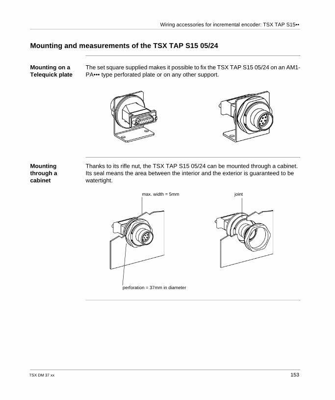
Wiring accessories for incremental encoder: TSX TAP S15••
Mounting and measurements of the TSX TAP S15 05/24
Mounting on a Telequick plate
The set square supplied makes it possible to fix the TSX TAP S15 05/24 on an AM1-PA••• type perforated plate or on any other support.
Mounting through a cabinet
Thanks to its rifle nut, the TSX TAP S15 05/24 can be mounted through a cabinet. Its seal means the area between the interior and the exterior is guaranteed to be watertight.
max. width = 5mm joint
perforation = 37mm in diameter
TSX DM 37 xx 153
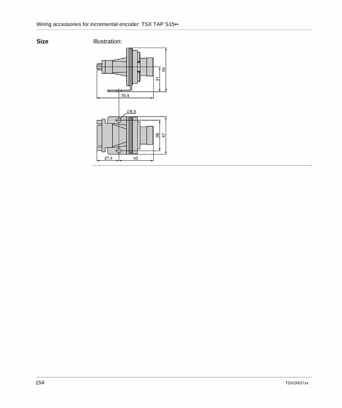
Wiring accessories for incremental encoder: TSX TAP S15••
Size Illustration:
154 TSX DM 37 xx
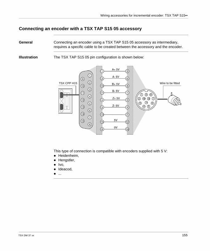
Wiring accessories for incremental encoder: TSX TAP S15••
Connecting an encoder with a TSX TAP S15 05 accessory
General Connecting an encoder using a TSX TAP S15 05 accessory as intermediary, requires a specific cable to be created between the accessory and the encoder.
Illustration The TSX TAP S15 05 pin configuration is shown below:
This type of connection is compatible with encoders supplied with 5 V: Heidenheim, Hengstler, Ivo, Ideacod, ...
TSX CPP H15 Wire to be fitted
TSX DM 37 xx 155
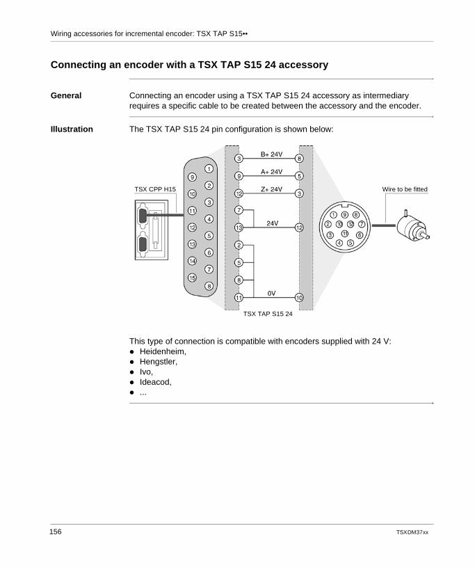
Wiring accessories for incremental encoder: TSX TAP S15••
Connecting an encoder with a TSX TAP S15 24 accessory
General Connecting an encoder using a TSX TAP S15 24 accessory as intermediary requires a specific cable to be created between the accessory and the encoder.
Illustration The TSX TAP S15 24 pin configuration is shown below:
This type of connection is compatible with encoders supplied with 24 V: Heidenheim, Hengstler, Ivo, Ideacod, ...
TSX CPP H15 Wire to be fitted
TSX TAP S15 24
156 TSX DM 37 xx
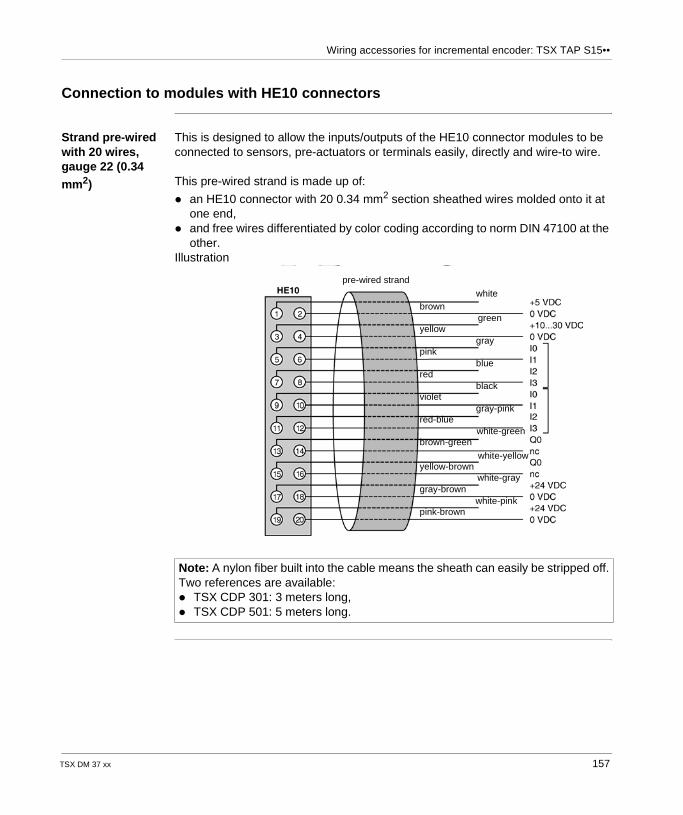
Wiring accessories for incremental encoder: TSX TAP S15••
Connection to modules with HE10 connectors
Strand pre-wired with 20 wires, gauge 22 (0.34
mm2)
This is designed to allow the inputs/outputs of the HE10 connector modules to be connected to sensors, pre-actuators or terminals easily, directly and wire-to wire.
This pre-wired strand is made up of:
an HE10 connector with 20 0.34 mm2 section sheathed wires molded onto it at one end,
and free wires differentiated by color coding according to norm DIN 47100 at the other.
Illustration
Note: A nylon fiber built into the cable means the sheath can easily be stripped off.Two references are available: TSX CDP 301: 3 meters long, TSX CDP 501: 5 meters long.
pre-wired strand
brown
yellow
pink
red
violet
red-blue
brown-green
yellow-brown
gray-brown
pink-brown
white
green
gray
blue
black
gray-pink
white-green
white-yellow
white-gray
white-pink
TSX DM 37 xx 157
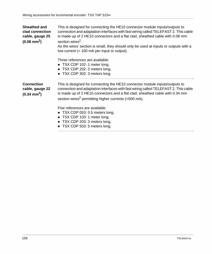
Wiring accessories for incremental encoder: TSX TAP S15••
Sheathed and clad connection cable, gauge 25 (0.08 mm2)
This is designed for connecting the HE10 connector module inputs/outputs to connection and adaptation interfaces with fast wiring called TELEFAST 2. This cable is made up of 2 HE10 connectors and a flat clad, sheathed cable with 0.08 mm
section wires2.As the wires’ section is small, they should only be used at inputs or outputs with a low current (< 100 mA per input or output).
Three references are available: TSX CDP 102: 1 meter long, TSX CDP 202: 2 meters long, TSX CDP 302: 3 meters long.
Connection cable, gauge 22
(0.34 mm2)
This is designed for connecting the HE10 connector module inputs/outputs to connection and adaptation interfaces with fast wiring called TELEFAST 2. This cable is made up of 2 HE10 connectors and a flat clad, sheathed cable with 0.34 mm
section wires2 permitting higher currents (<500 mA).
Five references are available: TSX CDP 053: 0.5 meters long, TSX CDP 103: 1 meter long, TSX CDP 203: 3 meters long, TSX CDP 503: 5 meters long.
158 TSX DM 37 xx
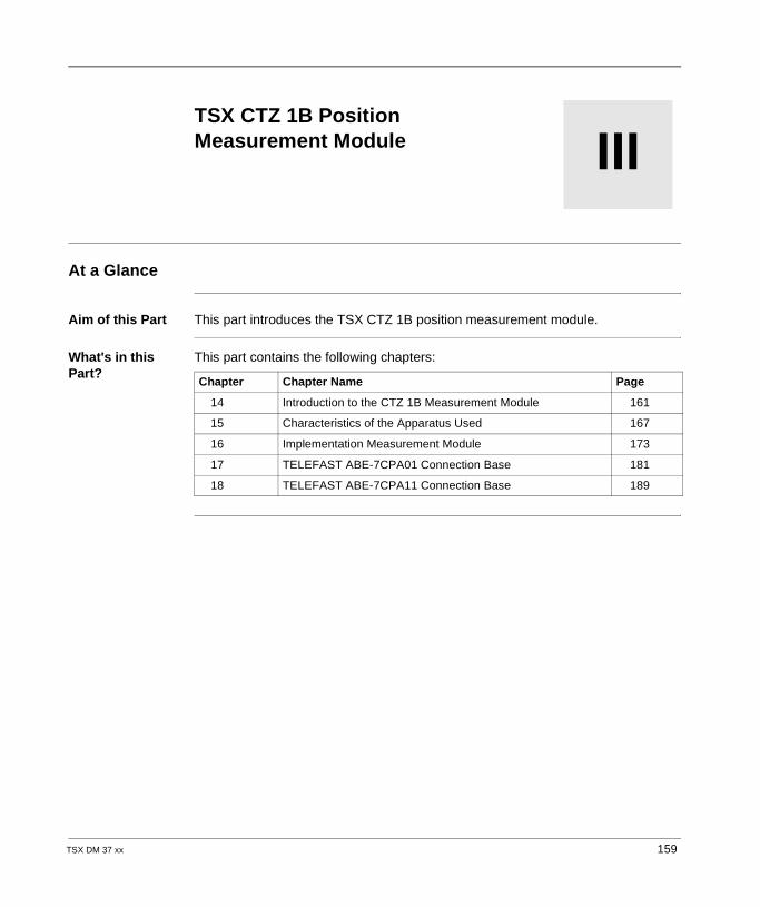
TSX DM 37 xx
III
TSX CTZ 1B Position Measurement ModuleAt a Glance
Aim of this Part This part introduces the TSX CTZ 1B position measurement module.
What's in this Part?
This part contains the following chapters:
Chapter Chapter Name Page
14 Introduction to the CTZ 1B Measurement Module 161
15 Characteristics of the Apparatus Used 167
16 Implementation Measurement Module 173
17 TELEFAST ABE-7CPA01 Connection Base 181
18 TELEFAST ABE-7CPA11 Connection Base 189
159

TSX CTZ 1B Position Measurement Module
160 TSX DM 37 xx
TSX DM 37 xx
14
Introduction to the CTZ 1B Measurement ModuleAt a Glance
Aim of this Chapter
This chapter deals with the TSX CTZ 1B measurement module associated with the absolute SSI encoder.
What's in this Chapter?
This chapter contains the following topics:
Topic Page
General Information on the Measurement Module 162
Physical Description of the Module 163
Number of Channels Managed by a TSX 37 164
Installation and Assembly of TSX CTZ 1B Modules 165
161
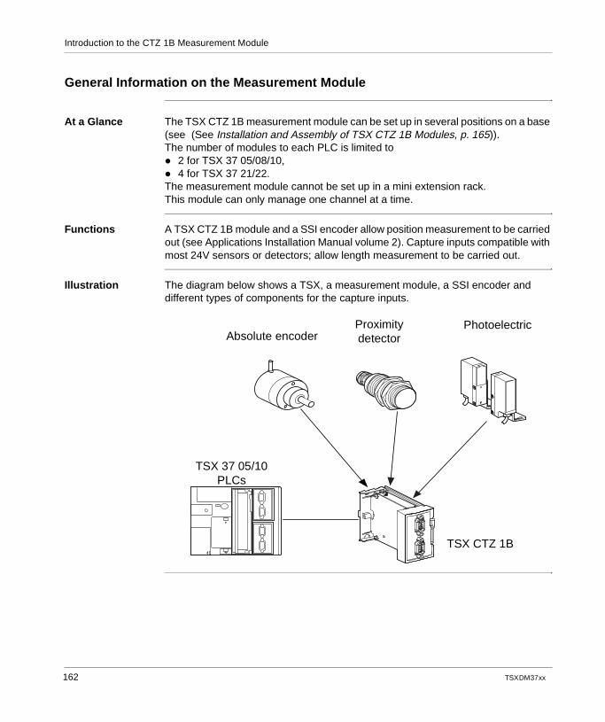
Introduction to the CTZ 1B Measurement Module
General Information on the Measurement Module
At a Glance The TSX CTZ 1B measurement module can be set up in several positions on a base (see (See Installation and Assembly of TSX CTZ 1B Modules, p. 165)).The number of modules to each PLC is limited to 2 for TSX 37 05/08/10, 4 for TSX 37 21/22.The measurement module cannot be set up in a mini extension rack.This module can only manage one channel at a time.
Functions A TSX CTZ 1B module and a SSI encoder allow position measurement to be carried out (see Applications Installation Manual volume 2). Capture inputs compatible with most 24V sensors or detectors; allow length measurement to be carried out.
Illustration The diagram below shows a TSX, a measurement module, a SSI encoder and different types of components for the capture inputs.
TSX 37 05/10PLCs
TSX CTZ 1B
PhotoelectricProximitydetectorAbsolute encoder
162 TSX DM 37 xx
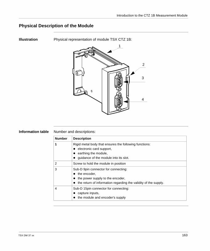
Introduction to the CTZ 1B Measurement Module
Physical Description of the Module
Illustration Physical representation of module TSX CTZ 1B:
Information table Number and descriptions:
1
2
3
4
Number Description
1 Rigid metal body that ensures the following functions: electronic card support, earthing the module, guidance of the module into its slot.
2 Screw to hold the module in position
3 Sub-D 9pin connector for connecting: the encoder, the power supply to the encoder, the return of information regarding the validity of the supply.
4 Sub-D 15pin connector for connecting: capture inputs, the module and encoder's supply
TSX DM 37 xx 163
Introduction to the CTZ 1B Measurement Module
Number of Channels Managed by a TSX 37
At a Glance This module occupies the equivalent of one type CTZ1A counting channel.
All the TSX 37 (05/08/10/10/21/22) PLCs can manage several counting or measurement channels, and depending on the type of TSX 37 PLC, they can have: two 500 Hz counting channels on discrete inputs, two built-in 10 kHz counting channels, one or more counting channels on module TSX CTZ1A/2A 40kHz or 2AA
500kHz, one or more absolute SSI encoder channels on module TSX CTZ1B.The maximum number of modules, which can be installed on a TSX 37 PLC, will depend on the number of channels already used in counting 500Hz, 10kHz, 40kHz or 500kHz.
The limit for the number of CTZ modules is: 2 TSX CTZ modules for a TSX 37 05/08/10 PLC, 4 TSX CTZ modules for a TSX 37 21/22 PLC.
The limit for the number of channels from CTZ modules is: 7 channels if base or discrete counting is not used, 6 channels if base counting or discrete input is used, 5 channels if base counting or discrete input is used,
164 TSX DM 37 xx
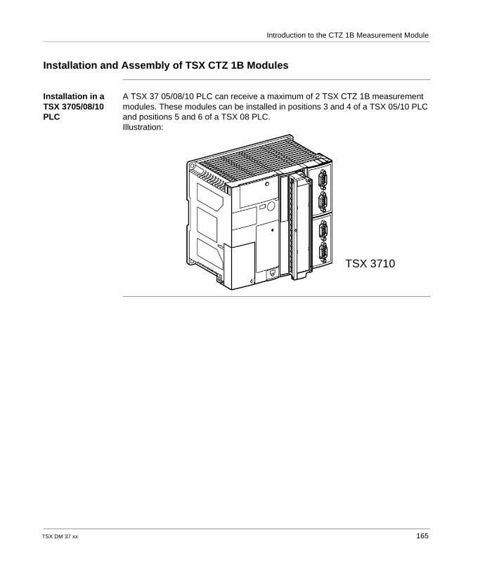
Introduction to the CTZ 1B Measurement Module
Installation and Assembly of TSX CTZ 1B Modules
Installation in a TSX 3705/08/10 PLC
A TSX 37 05/08/10 PLC can receive a maximum of 2 TSX CTZ 1B measurement modules. These modules can be installed in positions 3 and 4 of a TSX 05/10 PLC and positions 5 and 6 of a TSX 08 PLC.Illustration:
TSX 3710
TSX DM 37 xx 165
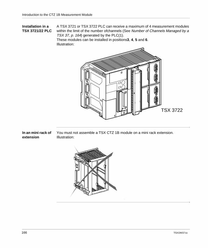
Introduction to the CTZ 1B Measurement Module
Installation in a TSX 3721/22 PLC
A TSX 3721 or TSX 3722 PLC can receive a maximum of 4 measurement modules within the limit of the number ofchannels (See Number of Channels Managed by a TSX 37, p. 164) generated by the PLC(1).These modules can be installed in positions3, 4, 5 and 6.Illustration:
In an mini rack of extension
You must not assemble a TSX CTZ 1B module on a mini rack extension.Illustration:
TSX 3722
166 TSX DM 37 xx
TSX DM 37 xx
15
Characteristics of the Apparatus UsedAt a Glance
Aim of this Chapter
This chapter aims to introduce the encoder module characteristics.
What's in this Chapter?
This chapter contains the following topics:
Topic Page
Encoder Selection 168
Selection and Protection of the Encoder Power Supply 170
General Characteristics of the TSX CTZ 1B Module 171
Capture Input Characteristics 172
167
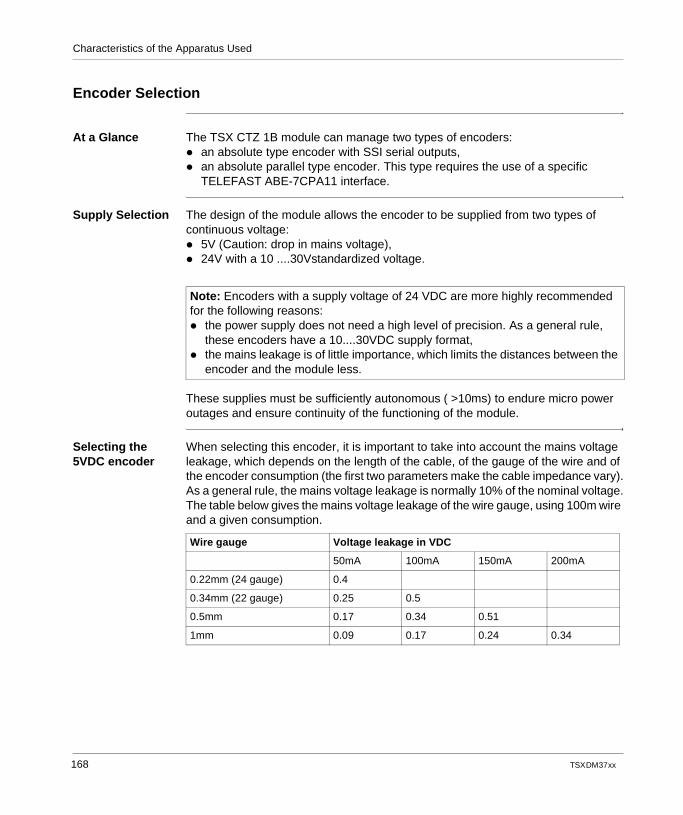
Characteristics of the Apparatus Used
Encoder Selection
At a Glance The TSX CTZ 1B module can manage two types of encoders: an absolute type encoder with SSI serial outputs, an absolute parallel type encoder. This type requires the use of a specific
TELEFAST ABE-7CPA11 interface.
Supply Selection The design of the module allows the encoder to be supplied from two types of continuous voltage: 5V (Caution: drop in mains voltage), 24V with a 10 ....30Vstandardized voltage.
These supplies must be sufficiently autonomous ( >10ms) to endure micro power outages and ensure continuity of the functioning of the module.
Selecting the 5VDC encoder
When selecting this encoder, it is important to take into account the mains voltage leakage, which depends on the length of the cable, of the gauge of the wire and of the encoder consumption (the first two parameters make the cable impedance vary).As a general rule, the mains voltage leakage is normally 10% of the nominal voltage.The table below gives the mains voltage leakage of the wire gauge, using 100m wire and a given consumption.
Note: Encoders with a supply voltage of 24 VDC are more highly recommended for the following reasons: the power supply does not need a high level of precision. As a general rule,
these encoders have a 10....30VDC supply format, the mains leakage is of little importance, which limits the distances between the
encoder and the module less.
Wire gauge Voltage leakage in VDC
50mA 100mA 150mA 200mA
0.22mm (24 gauge) 0.4
0.34mm (22 gauge) 0.25 0.5
0.5mm 0.17 0.34 0.51
1mm 0.09 0.17 0.24 0.34
168 TSX DM 37 xx
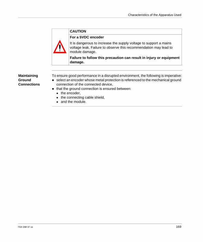
Characteristics of the Apparatus Used
Maintaining Ground Connections
To ensure good performance in a disrupted environment, the following is imperative: select an encoder whose metal protection is referenced to the mechanical ground
connection of the connected device, that the ground connection is ensured between:
the encoder, the connecting cable shield, and the module.
CAUTION
For a 5VDC encoder
It is dangerous to increase the supply voltage to support a mains voltage leak. Failure to observe this recommendation may lead to module damage.
Failure to follow this precaution can result in injury or equipment damage.
TSX DM 37 xx 169
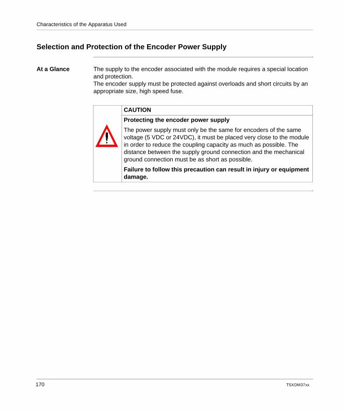
Characteristics of the Apparatus Used
Selection and Protection of the Encoder Power Supply
At a Glance The supply to the encoder associated with the module requires a special location and protection.The encoder supply must be protected against overloads and short circuits by an appropriate size, high speed fuse.
CAUTION
Protecting the encoder power supply
The power supply must only be the same for encoders of the same voltage (5 VDC or 24VDC), it must be placed very close to the module in order to reduce the coupling capacity as much as possible. The distance between the supply ground connection and the mechanical ground connection must be as short as possible.
Failure to follow this precaution can result in injury or equipment damage.
170 TSX DM 37 xx
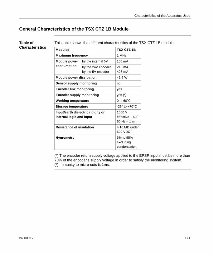
Characteristics of the Apparatus Used
General Characteristics of the TSX CTZ 1B Module
Table of Characteristics
This table shows the different characteristics of the TSX CTZ 1B module:
(*) The encoder return supply voltage applied to the EPSR input must be more than 70% of the encoder's supply voltage in order to satisfy the monitoring system.(*) Immunity to micro-cuts is 1ms.
Modules TSX CTZ 1B
Maximum frequency 1 MHz
Module power consumption
by the internal 5V 100 mA
by the 24V encoderby the 5V encoder
<15 mA<25 mA
Module power dissipation <1.5 W
Sensor supply monitoring no
Encoder link monitoring yes
Encoder supply monitoring yes (*)
Working temperature 0 to 60°C
Storage temperature -25° to +70°C
Input/earth dielectric rigidity or internal logic and input
1000 V effective – 50/60 Hz – 1 mn
Resistance of insulation > 10 MΩ under 500 VDC
Hygrometry 5% to 95% excluding condensation
TSX DM 37 xx 171
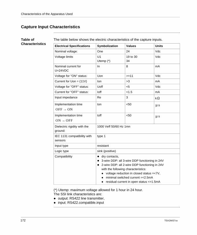
Characteristics of the Apparatus Used
Capture Input Characteristics
Table of Characteristics
The table below shows the electric characteristics of the capture inputs.
(*) Utemp: maximum voltage allowed for 1 hour in 24 hour.The SSI link characteristics are: output: RS422 line transmitter, input: RS422.compatible.input
Electrical Specifications Symbolization Values Units
Nominal voltage: One 24 Vdc
Voltage limits U1Utemp (*)
19 to 3034
Vdc
Nominal current for U=24VDC
In 8 mA
Voltage for "ON" status: Uon >=11 Vdc
Current for Uon = (11V) Ion >3 mA
Voltage for "OFF" status: Uoff <5 Vdc
Current for "OFF" status: Ioff <1.5 mA
Input impedance Re 3 k
Implementation time
ton <50 s
Implementation time toff <50 s
Dielectric rigidity with the ground:
1000 Veff 50/60 Hz 1mn
IEC 1131 compatibility with sensors
type 1
Input type resistant
Logic type sink (positive)
Compatibility dry contacts, 3-wire DDP: all 3-wire DDP functioning in 24V 2-wire DDP: all 2-wire DDP functioning in 24V
with the following characteristics: voltage reduction in closed status =<7V, minimal switched current =<2.5mA residual current in open status =>1.5mA
Ω
OFF ON→µ
ON OFF→µ
172 TSX DM 37 xx
TSX DM 37 xx
16
Implementation Measurement ModuleAt a Glance
Aim of this Chapter
This chapter deals with the implementation of module TSX CTZ 1B.
What's in this Chapter?
This chapter contains the following topics:
Topic Page
Installation Precautions 174
Wiring Precautions 175
Link between an Encoder and the TSX CTZ 1B Module 176
Linking the Encoder Supply and Capture Inputs 179
173
Implementation Measurement Module
Installation Precautions
At a glance In order to ensure good working order, certain precautions must be taken during the implementation and removal of the module, connection and disconnection of the connectors on the front face of the module and the (dis)connection of the module and connector's clamping screws.
Implementation and removal of the module
The implementation and removal of the module must only take place while the PLC is not connected to the power supply (this gives physical and hardware protection).
Connection and Disconnection of the Connectors
Connection or disconnection of a connector on the front face of the module should always take place when the encoder power supply is off.Encoders cannot endure a start-up or a simultaneous cut-out of signals and power supply.
Screw Tightening
In order to maintain a ground connection and to reduce electromagnetic disturbances, you should screw the clamping screws in correctly (clamping torque = 0.5Nm).
174 TSX DM 37 xx

Implementation Measurement Module
Wiring Precautions
At a Glance In order to guarantee the good working order of the PLC, you should respect certain basic rules, which will be explained below.
Wire Gauge The gauge of the wire should be enough to reduce mains leakages and the heat of the cable. In fact, the cable's impedance being inversely proportional to the gauge, if you use larger gauge wire, mains leakage will be reduced.
Wire Location Linking cables must be kept away from any source of radiation generated by the commutation of electric power circuits, which could provoke electromagnetic disturbances. In fact, this could cause an error in the position measurement
Encoder Signals Linking Cables
Linking cables should conform to the following electric rules: they should be shielded, the whole connection should always be grounded, shielding should be linked to the mechanical ground connection on the module
side and the encoder side, the encoder cable should only convey signals relating to the encoder
TSX DM 37 xx 175
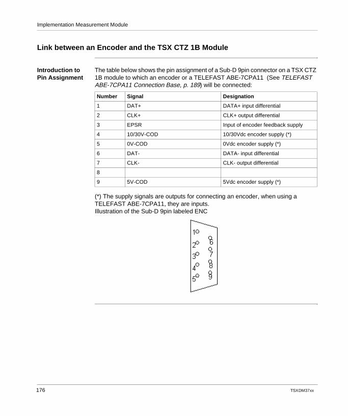
Implementation Measurement Module
Link between an Encoder and the TSX CTZ 1B Module
Introduction to Pin Assignment
The table below shows the pin assignment of a Sub-D 9pin connector on a TSX CTZ 1B module to which an encoder or a TELEFAST ABE-7CPA11 (See TELEFAST ABE-7CPA11 Connection Base, p. 189) will be connected:
(*) The supply signals are outputs for connecting an encoder, when using a TELEFAST ABE-7CPA11, they are inputs.Illustration of the Sub-D 9pin labeled ENC
Number Signal Designation
1 DAT+ DATA+ input differential
2 CLK+ CLK+ output differential
3 EPSR Input of encoder feedback supply
4 10/30V-COD 10/30Vdc encoder supply (*)
5 0V-COD 0Vdc encoder supply (*)
6 DAT- DATA- input differential
7 CLK- CLK- output differential
8
9 5V-COD 5Vdc encoder supply (*)
176 TSX DM 37 xx
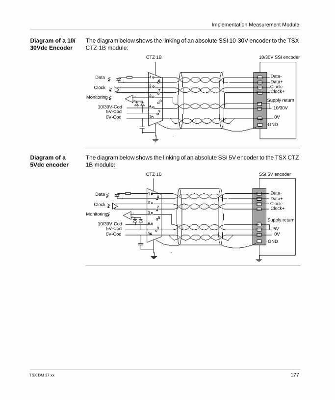
Implementation Measurement Module
Diagram of a 10/30Vdc Encoder
The diagram below shows the linking of an absolute SSI 10-30V encoder to the TSX CTZ 1B module:
Diagram of a 5Vdc encoder
The diagram below shows the linking of an absolute SSI 5V encoder to the TSX CTZ 1B module:
Data
Clock
Monitoring
10/30V-Cod5V-Cod0V-Cod
CTZ 1B 10/30V SSI encoder
Data-Data+Clock-Clock+
Supply return
10/30V
0V
GND
Data
Clock
Monitoring
10/30V-Cod5V-Cod0V-Cod
CTZ 1B SSI 5V encoder
Data-Data+Clock-Clock+
Supply return
5V0V
GND
TSX DM 37 xx 177
Implementation Measurement Module
Recommen-dations
Below are a few recommendations for linking the encoder: The signals DATA +/- and CLK +/- must be linked with a twisted pair, the cable shielding must be linked to the mechanical ground connection at each
end, the EPSR input must be linked to the "+" module of the encoder side supply, if
this does not have a "+" feedback output supply. it is advisable to connect a 0V twisted pair to limit the common mode between the
module and the encoder by doubling the gauge.
CAUTION
Recommendations on input/output pin assignment
Before making any connection between the encoder and the module, check the pin assignment recommended by the encoder manufacturer.
Failure to follow this precaution can result in injury or equipment damage.
178 TSX DM 37 xx
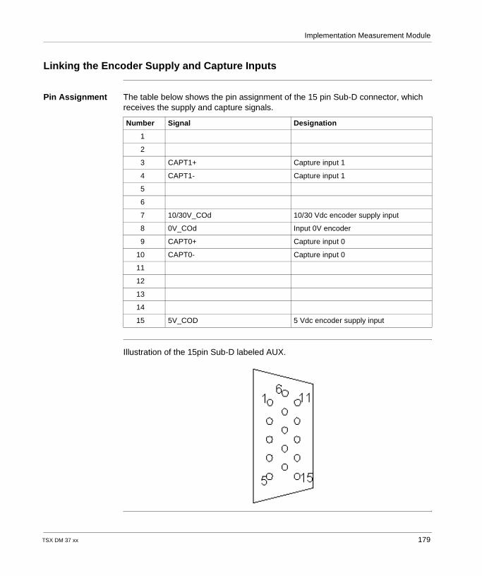
Implementation Measurement Module
Linking the Encoder Supply and Capture Inputs
Pin Assignment The table below shows the pin assignment of the 15 pin Sub-D connector, which receives the supply and capture signals.
Illustration of the 15pin Sub-D labeled AUX.
Number Signal Designation
1
2
3 CAPT1+ Capture input 1
4 CAPT1- Capture input 1
5
6
7 10/30V_COd 10/30 Vdc encoder supply input
8 0V_COd Input 0V encoder
9 CAPT0+ Capture input 0
10 CAPT0- Capture input 0
11
12
13
14
15 5V_COD 5 Vdc encoder supply input
TSX DM 37 xx 179

Implementation Measurement Module
180 TSX DM 37 xx
TSX DM 37 xx
17
TELEFAST ABE-7CPA01 Connection BaseAt a Glance
Aim of this Chapter
This chapter describes the use of TELEFAST for the TSX CTZ 1B module using connection diagrams.
What's in this Chapter?
This chapter contains the following topics:
Topic Page
Connecting TELEFAST 2: ABE-7CPA01 182
Connection diagram for the TELEFAST ABE-7CPA01 184
Description of the Screw Terminal Blocks for the TELEFAST ABE-7CPA01 186
181
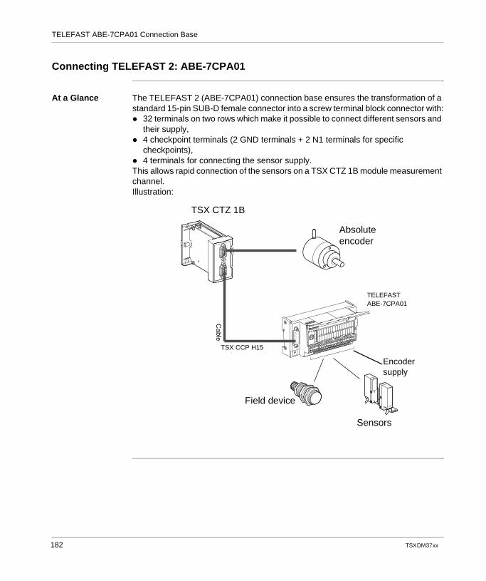
TELEFAST ABE-7CPA01 Connection Base
Connecting TELEFAST 2: ABE-7CPA01
At a Glance The TELEFAST 2 (ABE-7CPA01) connection base ensures the transformation of a standard 15-pin SUB-D female connector into a screw terminal block connector with: 32 terminals on two rows which make it possible to connect different sensors and
their supply, 4 checkpoint terminals (2 GND terminals + 2 N1 terminals for specific
checkpoints), 4 terminals for connecting the sensor supply.This allows rapid connection of the sensors on a TSX CTZ 1B module measurement channel.Illustration:
TSX CTZ 1B
Absoluteencoder
Field device
Sensors
TELEFAST ABE-7CPA01
Cable
TSX CCP H15
Encodersupply
182 TSX DM 37 xx
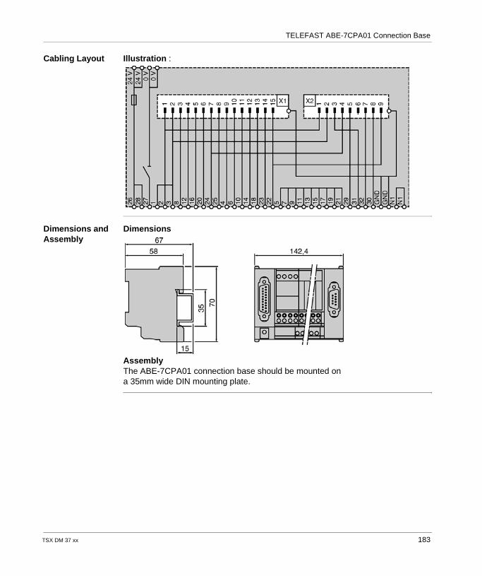
TELEFAST ABE-7CPA01 Connection Base
Cabling Layout Illustration :
Dimensions and Assembly
Dimensions
AssemblyThe ABE-7CPA01 connection base should be mounted on a 35mm wide DIN mounting plate.
TSX DM 37 xx 183
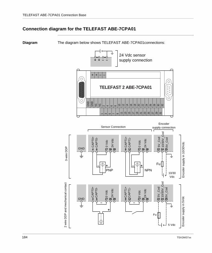
TELEFAST ABE-7CPA01 Connection Base
Connection diagram for the TELEFAST ABE-7CPA01
Diagram The diagram below shows TELEFAST ABE-7CPA01connections:
––++
GN
DG
ND
N1
N1
2 4 6 8 10 12 14 16 18 20 22 24 26 28 30 32
1 3 5 7 9 11 13 15 17 19 21 23 25 27 29 31
4 6 27 26 28
– +PNP
8 12 27 26 28
– +NPN
22 24 25
4 6 27 26 28–
+
8 12 27 26 28 22 24 25–
+ + – –
Fu
TELEFAST 2 ABE-7CPA01
24 Vdc sensorsupply connection
Sensor ConnectionEncoder
supply connection
3-w
ire D
DP
2 w
ire D
DP
and
mec
hani
cal c
onta
ct
Enc
oder
sup
ply
in 1
0/30
Vdc
Enc
oder
sup
ply
in 5
Vdc
CA
PT
0+C
AP
T0-
CA
PT
1+C
AP
T1-
0 V
dc
24 V
dc
0 V
dc
24 V
dc
CA
PT
0+C
AP
T0-
CA
PT
1+C
AP
T1-
0 V
dc
24 V
dc
0 V
dc
24 V
dcGND
GND
5V_C
od
0V_C
od10
/30V
_Cod
10/30 Vdc
5 Vdc
Fu
5V_C
od
0V_C
od10
/30V
_Cod
184 TSX DM 37 xx
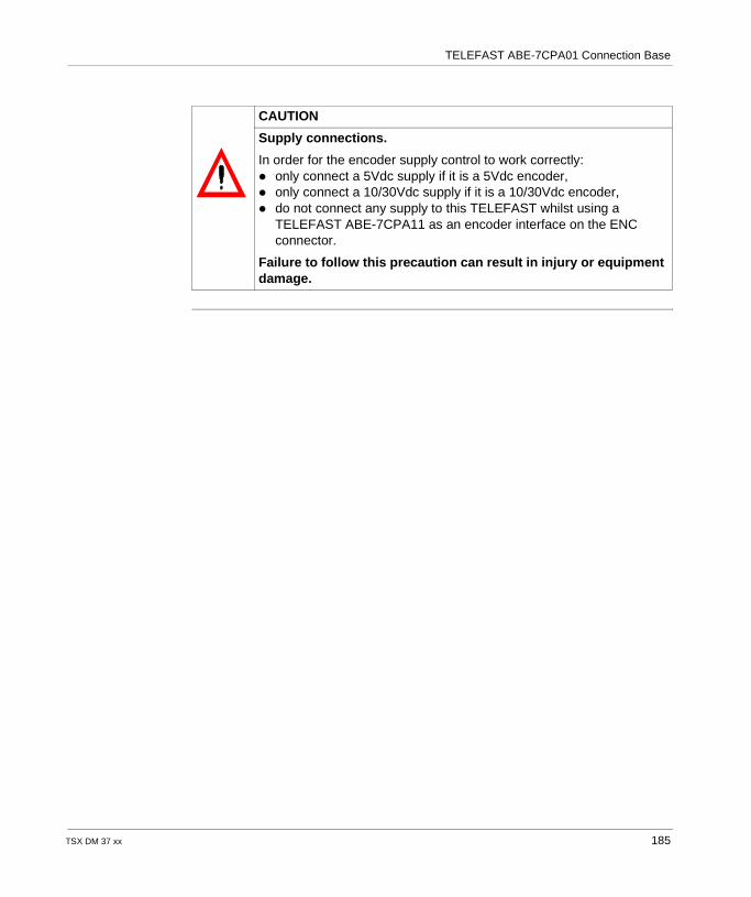
TELEFAST ABE-7CPA01 Connection Base
CAUTION
Supply connections.
In order for the encoder supply control to work correctly: only connect a 5Vdc supply if it is a 5Vdc encoder, only connect a 10/30Vdc supply if it is a 10/30Vdc encoder, do not connect any supply to this TELEFAST whilst using a
TELEFAST ABE-7CPA11 as an encoder interface on the ENC connector.
Failure to follow this precaution can result in injury or equipment damage.
TSX DM 37 xx 185
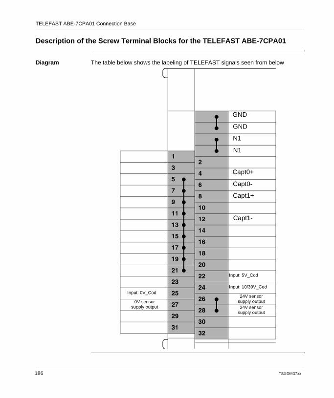
TELEFAST ABE-7CPA01 Connection Base
Description of the Screw Terminal Blocks for the TELEFAST ABE-7CPA01
Diagram The table below shows the labeling of TELEFAST signals seen from below
GND
GND
N1
N1
Capt0+
Capt0-
Capt1+
Capt1-
Input: 5V_Cod
Input: 10/30V_CodInput: 0V_Cod
0V sensor supply output
24V sensor supply output24V sensor
supply output
186 TSX DM 37 xx
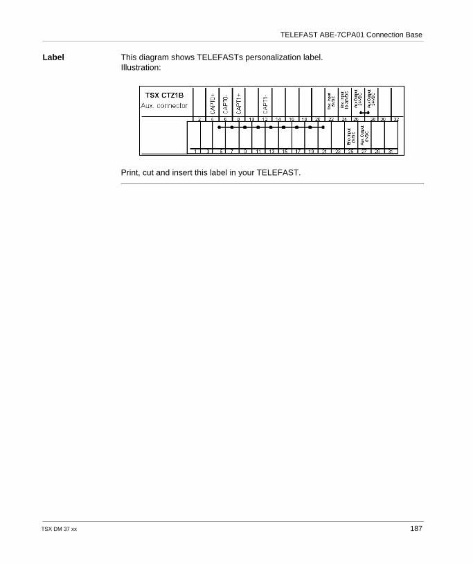
TELEFAST ABE-7CPA01 Connection Base
Label This diagram shows TELEFASTs personalization label.Illustration:
Print, cut and insert this label in your TELEFAST.
TSX DM 37 xx 187

TELEFAST ABE-7CPA01 Connection Base
188 TSX DM 37 xx
TSX DM 37 xx
18
TELEFAST ABE-7CPA11 Connection BaseAt a Glance
Aim of this Chapter
This chapter, using diagrams, describes connections and examples of usage of the TELEFAST ABE-7CPA11
What's in this Chapter?
This chapter contains the following topics:
Topic Page
TELEFAST 2 Connection and Adaptation Base: ABE-7CPA11 190
Connecting the TELEFAST ABE-7CPA11 to the TSX CTZ 1B Module 192
Physical Description of the TELEFAST 2: ABE-7CPA11 193
TELEFAST 2 Connection Base Characteristics: ABE-7CPA11 194
Connecting the TELEFAST 2 Base: ABE-7CPA11 197
Connecting Encoders Supplied with 10...30 V 199
Connecting Encoders Supplied with 5 V 201
Example of Multiplexing of Encoders Supplied with 5V 203
Example of a connection: an encoder connected by a TELEFAST to the TSX CTZ 1B ENC connector
204
Example of a connection: 4 encoders connected by 2 TELEFASTs to the TSX CTZ 1B ENC connector
205
Example of a connection: 4 encoders connected by 3 TELEFASTs to the TSX CTZ 1B ENC connector
208
Example of a connection: 4 encoders connected by 4 TELEFASTs to the TSX CTZ 1B ENC connector
210
Wiring Rules and Precautions 212
Configuration of the TELEFAST Connection Base 215
189
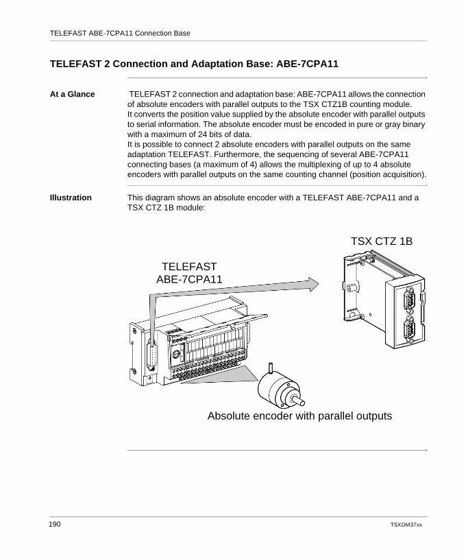
TELEFAST ABE-7CPA11 Connection Base
TELEFAST 2 Connection and Adaptation Base: ABE-7CPA11
At a Glance TELEFAST 2 connection and adaptation base: ABE-7CPA11 allows the connection of absolute encoders with parallel outputs to the TSX CTZ1B counting module.It converts the position value supplied by the absolute encoder with parallel outputs to serial information. The absolute encoder must be encoded in pure or gray binary with a maximum of 24 bits of data.It is possible to connect 2 absolute encoders with parallel outputs on the same adaptation TELEFAST. Furthermore, the sequencing of several ABE-7CPA11 connecting bases (a maximum of 4) allows the multiplexing of up to 4 absolute encoders with parallel outputs on the same counting channel (position acquisition).
Illustration This diagram shows an absolute encoder with a TELEFAST ABE-7CPA11 and a TSX CTZ 1B module:
TELEFAST ABE-7CPA11
TSX CTZ 1B
Absolute encoder with parallel outputs
190 TSX DM 37 xx
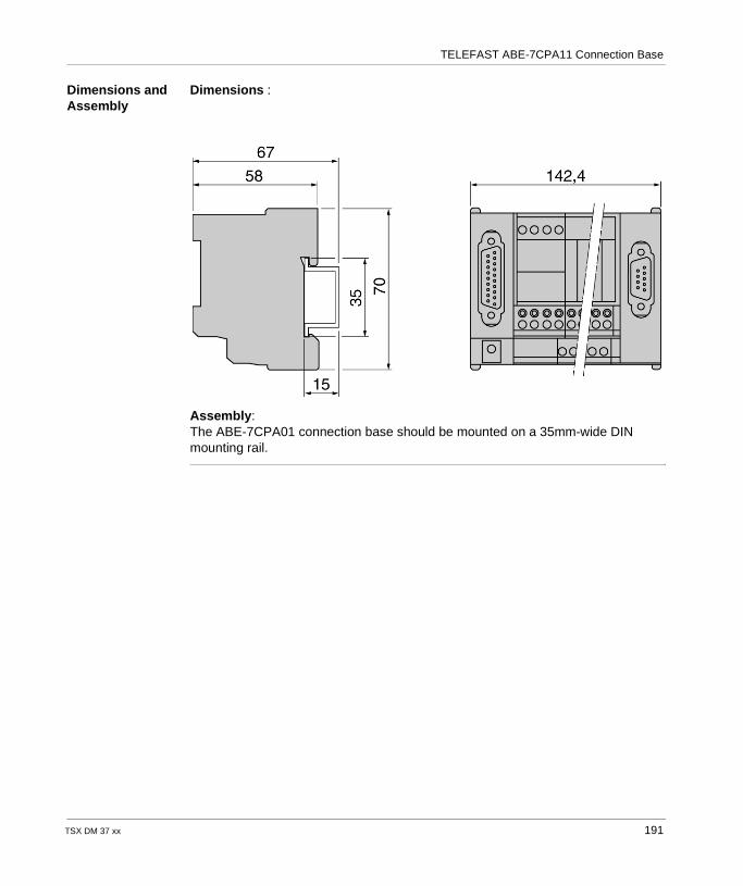
TELEFAST ABE-7CPA11 Connection Base
Dimensions and Assembly
Dimensions :
Assembly:The ABE-7CPA01 connection base should be mounted on a 35mm-wide DIN mounting rail.
TSX DM 37 xx 191
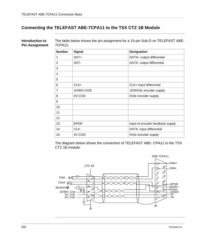
TELEFAST ABE-7CPA11 Connection Base
Connecting the TELEFAST ABE-7CPA11 to the TSX CTZ 1B Module
Introduction to Pin Assignment
The table below shows the pin assignment for a 15-pin Sub-D on TELEFAST ABE-7CPA11:
The diagram below shows the connection of TELEFAST ABE- CPA11 to the TSX CTZ 1B module:
Number Signal Designation
1 DAT+ DATA+ output differential
2 DAT- DATA- output differential
3
4
5
6 CLK+ CLK+ input differential
7 10/30V-COD 10/30Vdc encoder supply
8 0V-COD 0Vdc encoder supply
9
10
11
12
13 EPSR Input of encoder feedback supply
14 CLK- DATA- input differential
15 5V-COD 5Vdc encoder supply
CTZ 1B
Data
Clock
Monitoring
10/30V_Cod5V_Cod0V_Cod
ANE-7CPA11
Data+
Data-
Clock+Clock-10/30V5V0V
EPSR
192 TSX DM 37 xx
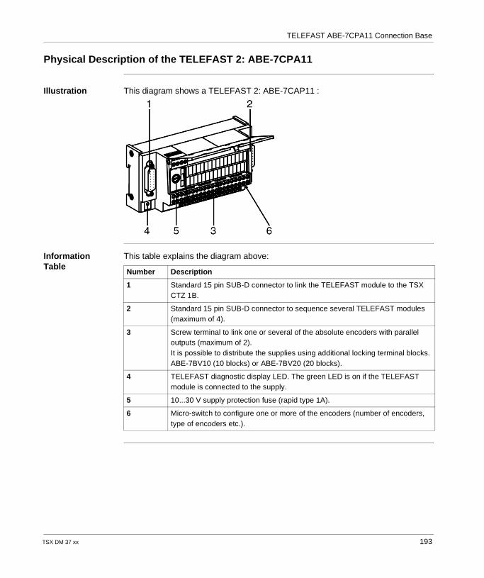
TELEFAST ABE-7CPA11 Connection Base
Physical Description of the TELEFAST 2: ABE-7CPA11
Illustration This diagram shows a TELEFAST 2: ABE-7CAP11 :
Information Table
This table explains the diagram above:
Number Description
1 Standard 15 pin SUB-D connector to link the TELEFAST module to the TSX CTZ 1B.
2 Standard 15 pin SUB-D connector to sequence several TELEFAST modules (maximum of 4).
3 Screw terminal to link one or several of the absolute encoders with parallel outputs (maximum of 2).It is possible to distribute the supplies using additional locking terminal blocks. ABE-7BV10 (10 blocks) or ABE-7BV20 (20 blocks).
4 TELEFAST diagnostic display LED. The green LED is on if the TELEFAST module is connected to the supply.
5 10...30 V supply protection fuse (rapid type 1A).
6 Micro-switch to configure one or more of the encoders (number of encoders, type of encoders etc.).
TSX DM 37 xx 193
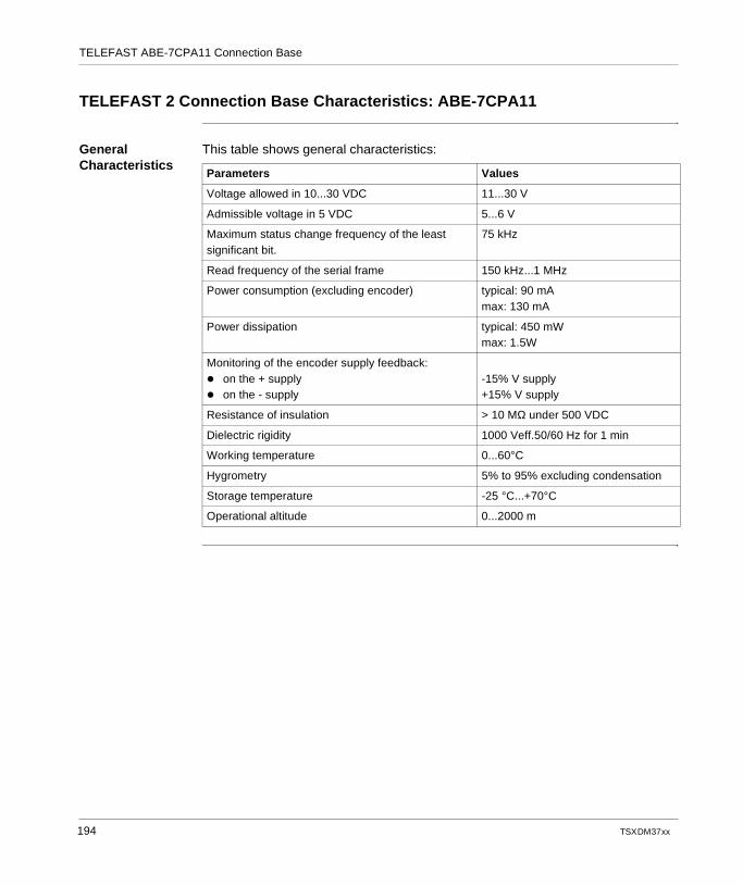
TELEFAST ABE-7CPA11 Connection Base
TELEFAST 2 Connection Base Characteristics: ABE-7CPA11
General Characteristics
This table shows general characteristics:
Parameters Values
Voltage allowed in 10...30 VDC 11...30 V
Admissible voltage in 5 VDC 5...6 V
Maximum status change frequency of the least significant bit.
75 kHz
Read frequency of the serial frame 150 kHz...1 MHz
Power consumption (excluding encoder) typical: 90 mAmax: 130 mA
Power dissipation typical: 450 mWmax: 1.5W
Monitoring of the encoder supply feedback: on the + supply on the - supply
-15% V supply+15% V supply
Resistance of insulation > 10 MΩ under 500 VDC
Dielectric rigidity 1000 Veff.50/60 Hz for 1 min
Working temperature 0...60°C
Hygrometry 5% to 95% excluding condensation
Storage temperature -25 °C...+70°C
Operational altitude 0...2000 m
194 TSX DM 37 xx
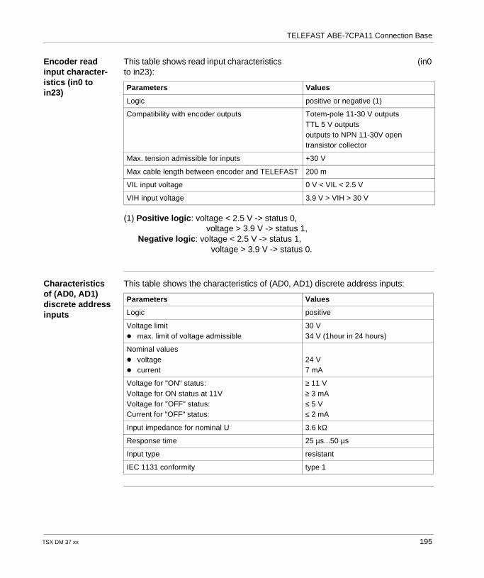
TELEFAST ABE-7CPA11 Connection Base
Encoder read input character-istics (in0 to in23)
This table shows read input characteristics (in0 to in23):
(1) Positive logic: voltage < 2.5 V -> status 0, voltage > 3.9 V -> status 1, Negative logic: voltage < 2.5 V -> status 1, voltage > 3.9 V -> status 0.
Characteristics of (AD0, AD1) discrete address inputs
This table shows the characteristics of (AD0, AD1) discrete address inputs:
Parameters Values
Logic positive or negative (1)
Compatibility with encoder outputs Totem-pole 11-30 V outputsTTL 5 V outputsoutputs to NPN 11-30V open transistor collector
Max. tension admissible for inputs +30 V
Max cable length between encoder and TELEFAST 200 m
VIL input voltage 0 V < VIL < 2.5 V
VIH input voltage 3.9 V > VIH > 30 V
Parameters Values
Logic positive
Voltage limit max. limit of voltage admissible
30 V34 V (1hour in 24 hours)
Nominal values voltage current
24 V7 mA
Voltage for "ON" status:Voltage for ON status at 11VVoltage for "OFF" status:Current for "OFF" status:
≥ 11 V≥ 3 mA≤ 5 V≤ 2 mA
Input impedance for nominal U 3.6 kΩ
Response time 25 µs...50 µs
Input type resistant
IEC 1131 conformity type 1
TSX DM 37 xx 195
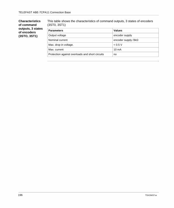
TELEFAST ABE-7CPA11 Connection Base
Characteristics of command outputs, 3 states of encoders (3STO, 3ST1)
This table shows the characteristics of command outputs, 3 states of encoders (3ST0, 3ST1)
Parameters Values
Output voltage encoder supply
Nominal current encoder supply /3kΩ
Max. drop in voltage. < 0.5 V
Max. current 10 mA
Protection against overloads and short circuits no
196 TSX DM 37 xx
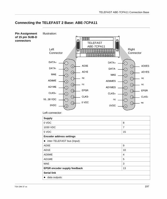
TELEFAST ABE-7CPA11 Connection Base
Connecting the TELEFAST 2 Base: ABE-7CPA11
Pin Assignment of 15 pin SUB-D connectors
Illustration:
Left connector:
Supply
0 VDC 8
1030 VDC 7
5 VDC 15
Encoder address settings
inter-TELEFAST bus (Input):
AD0E 9
AD1E 10
AD0ME 4
AD1ME 5
MAE 3
EPSR encoder supply feedback 13
Serial link
data outputs:
TELEFASTABE-7CPA11
LeftConnector
RightConnector
TSX DM 37 xx 197
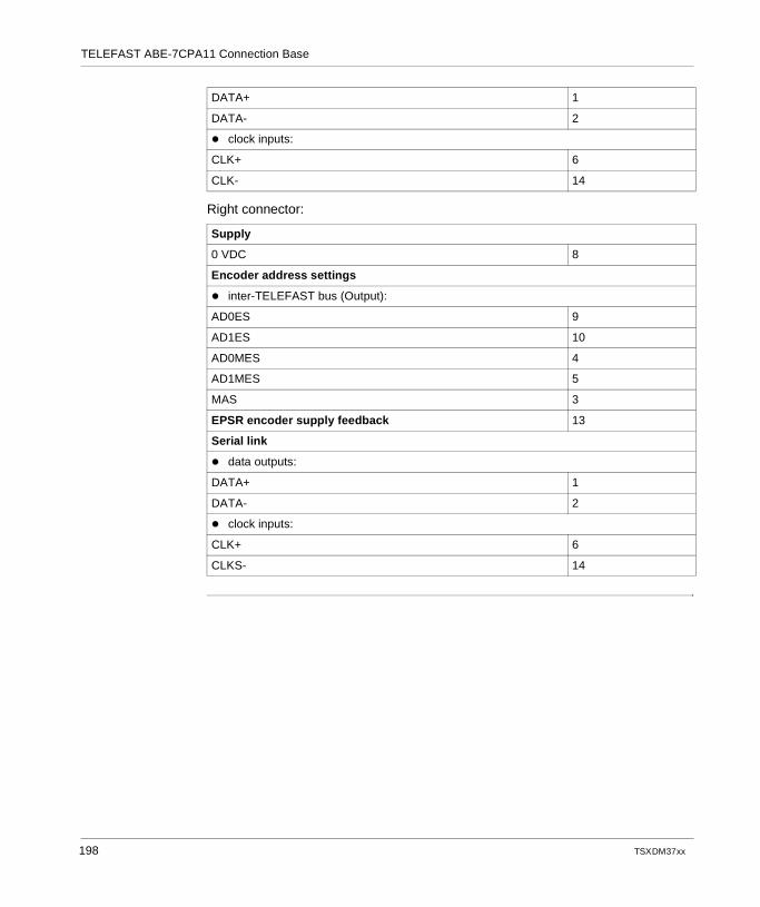
TELEFAST ABE-7CPA11 Connection Base
Right connector:
DATA+ 1
DATA- 2
clock inputs:
CLK+ 6
CLK- 14
Supply
0 VDC 8
Encoder address settings
inter-TELEFAST bus (Output):
AD0ES 9
AD1ES 10
AD0MES 4
AD1MES 5
MAS 3
EPSR encoder supply feedback 13
Serial link
data outputs:
DATA+ 1
DATA- 2
clock inputs:
CLK+ 6
CLKS- 14
198 TSX DM 37 xx
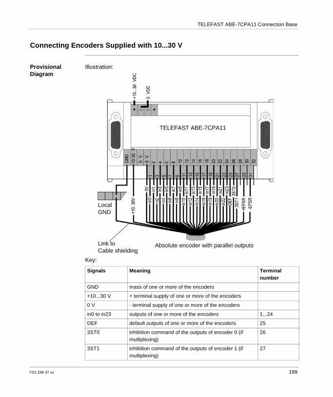
TELEFAST ABE-7CPA11 Connection Base
Connecting Encoders Supplied with 10...30 V
Provisional Diagram
Illustration:
Key:
Signals Meaning Terminal number
GND mass of one or more of the encoders
+10...30 V + terminal supply of one or more of the encoders
0 V - terminal supply of one or more of the encoders
in0 to in23 outputs of one or more of the encoders 1...24
DEF default outputs of one or more of the encoders 25
3ST0 inhibition command of the outputs of encoder 0 (if multiplexing)
26
3ST1 inhibition command of the outputs of encoder 1 (if multiplexing)
27
TELEFAST ABE-7CPA11
LocalGND
Link toCable shielding
Absolute encoder with parallel outputs
TSX DM 37 xx 199
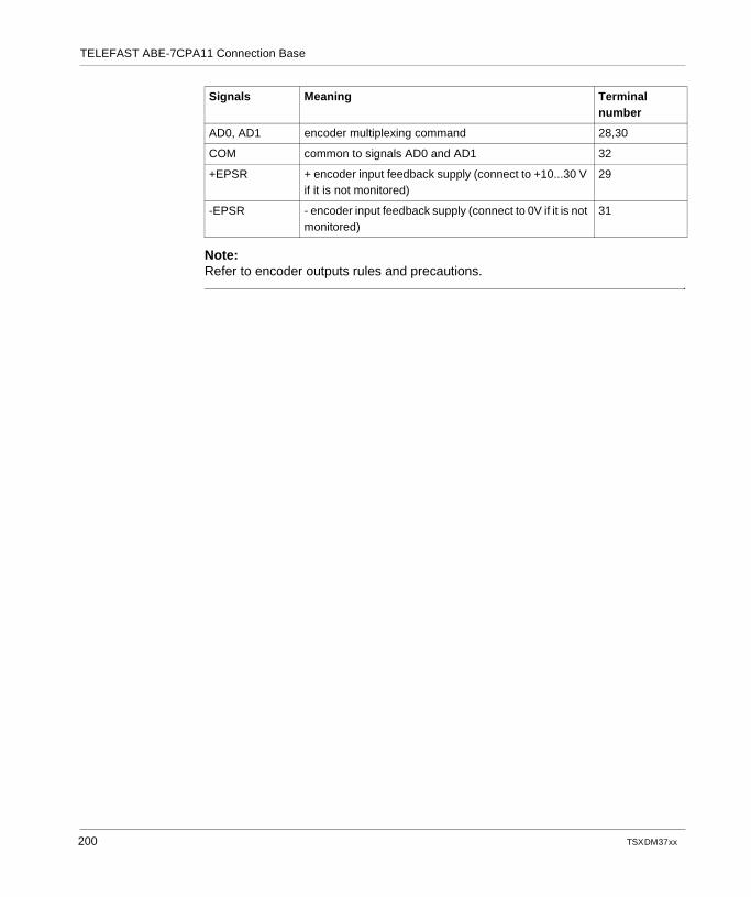
TELEFAST ABE-7CPA11 Connection Base
Note:Refer to encoder outputs rules and precautions.
AD0, AD1 encoder multiplexing command 28,30
COM common to signals AD0 and AD1 32
+EPSR + encoder input feedback supply (connect to +10...30 V if it is not monitored)
29
-EPSR - encoder input feedback supply (connect to 0V if it is not monitored)
31
Signals Meaning Terminal number
200 TSX DM 37 xx
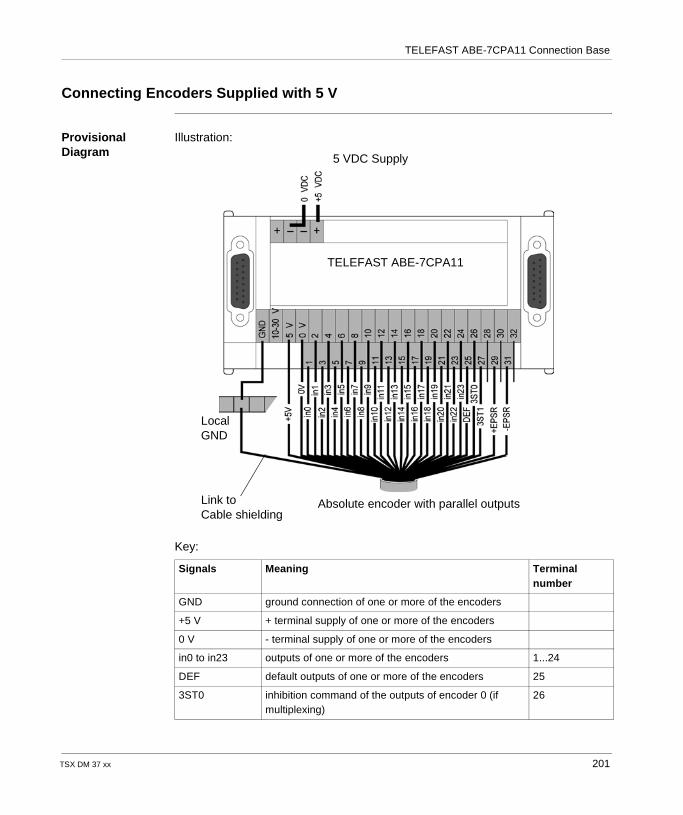
TELEFAST ABE-7CPA11 Connection Base
Connecting Encoders Supplied with 5 V
Provisional Diagram
Illustration:
Key:
Signals Meaning Terminal number
GND ground connection of one or more of the encoders
+5 V + terminal supply of one or more of the encoders
0 V - terminal supply of one or more of the encoders
in0 to in23 outputs of one or more of the encoders 1...24
DEF default outputs of one or more of the encoders 25
3ST0 inhibition command of the outputs of encoder 0 (if multiplexing)
26
TELEFAST ABE-7CPA11
LocalGND
Link toCable shielding
Absolute encoder with parallel outputs
5 VDC Supply
TSX DM 37 xx 201
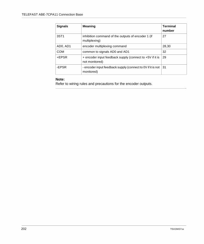
TELEFAST ABE-7CPA11 Connection Base
Note:Refer to wiring rules and precautions for the encoder outputs.
3ST1 inhibition command of the outputs of encoder 1 (if multiplexing)
27
AD0, AD1 encoder multiplexing command 28,30
COM common to signals AD0 and AD1 32
+EPSR + encoder input feedback supply (connect to +5V if it is not monitored)
29
-EPSR - encoder input feedback supply (connect to 0V if it is not monitored)
31
Signals Meaning Terminal number
202 TSX DM 37 xx
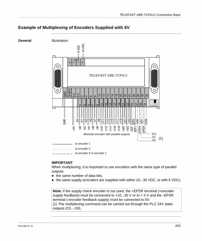
TELEFAST ABE-7CPA11 Connection Base
Example of Multiplexing of Encoders Supplied with 5V
General Illustration:
IMPORTANTWhen multiplexing, it is important to use encoders with the same type of parallel outputs: the same number of data bits, the same supply (encoders are supplied with either 10...30 VDC, or with 5 VDC).
Note: if the supply check encoder is not used, the +EPSR terminal (+encoder supply feedback) must be connected to +10...30 V or to + 5 V and the -EPSR terminal (-encoder feedback supply) must be connected to 0V.(1) The multiplexing command can be carried out through the PLC 24V static outputs (O1 - O0).
TELEFAST ABE-7CPA11
to encoder 1
to encoder 0
to encoder 0 or encoder 1
Absolute encoder with parallel outputsO1O0
(1)
TSX DM 37 xx 203
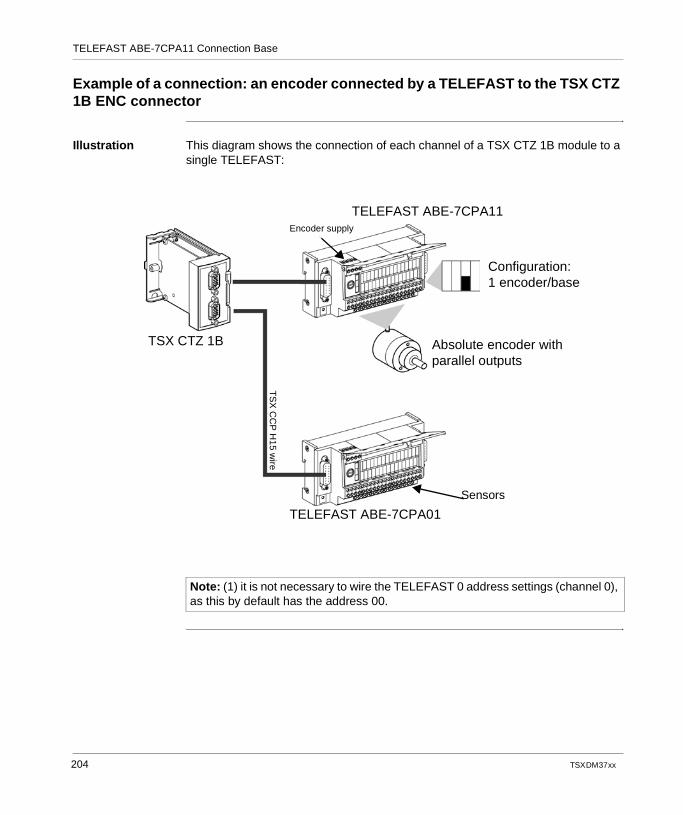
TELEFAST ABE-7CPA11 Connection Base
Example of a connection: an encoder connected by a TELEFAST to the TSX CTZ 1B ENC connector
Illustration This diagram shows the connection of each channel of a TSX CTZ 1B module to a single TELEFAST:
TELEFAST ABE-7CPA11Encoder supply
TSX CTZ 1B
Configuration:1 encoder/base
TELEFAST ABE-7CPA01
Absolute encoder with parallel outputs
TS
X C
CP
H15 w
ire
Sensors
Note: (1) it is not necessary to wire the TELEFAST 0 address settings (channel 0), as this by default has the address 00.
204 TSX DM 37 xx
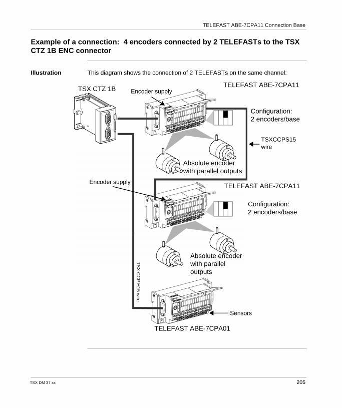
TELEFAST ABE-7CPA11 Connection Base
Example of a connection: 4 encoders connected by 2 TELEFASTs to the TSX CTZ 1B ENC connector
Illustration This diagram shows the connection of 2 TELEFASTs on the same channel:
TELEFAST ABE-7CPA11TSX CTZ 1B
Configuration:2 encoders/base
TELEFAST ABE-7CPA11
Absolute encoder with parallel outputs
TS
X C
CP
H15 w
ireConfiguration:2 encoders/base
Absolute encoder with parallel outputs
TELEFAST ABE-7CPA01
Encoder supply
Encoder supply
TSXCCPS15wire
Sensors
TSX DM 37 xx 205
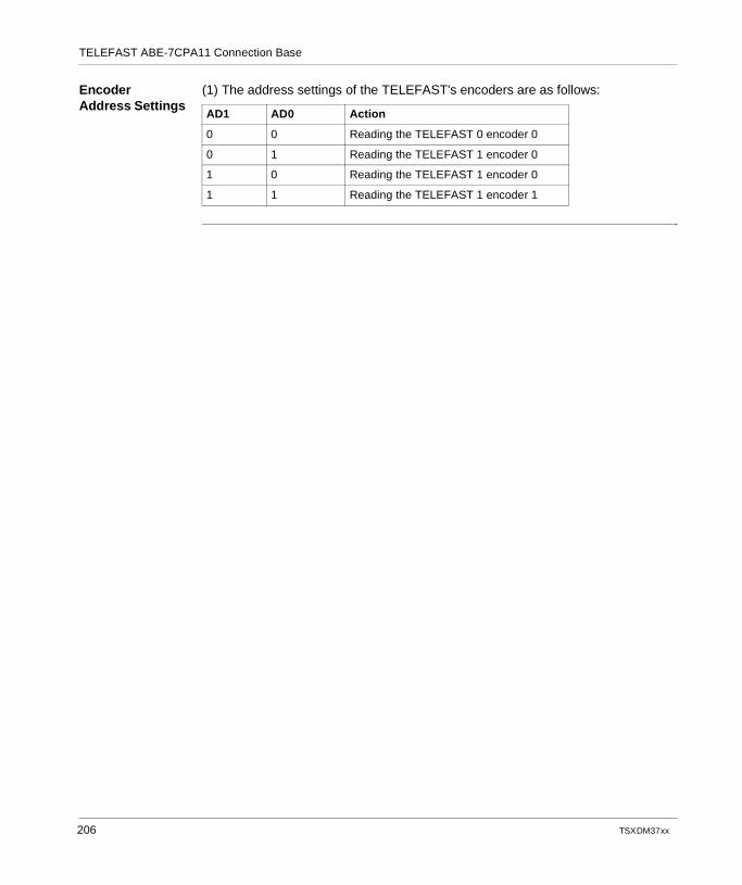
TELEFAST ABE-7CPA11 Connection Base
Encoder Address Settings
(1) The address settings of the TELEFAST's encoders are as follows:
AD1 AD0 Action
0 0 Reading the TELEFAST 0 encoder 0
0 1 Reading the TELEFAST 1 encoder 0
1 0 Reading the TELEFAST 1 encoder 0
1 1 Reading the TELEFAST 1 encoder 1
206 TSX DM 37 xx

TELEFAST ABE-7CPA11 Connection Base
TSX DM 37 xx 207
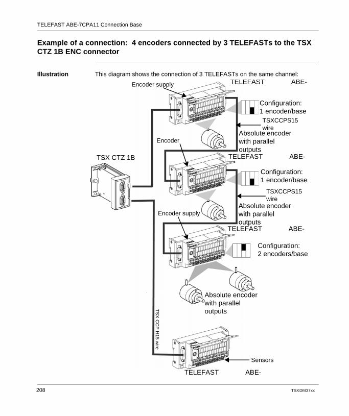
TELEFAST ABE-7CPA11 Connection Base
Example of a connection: 4 encoders connected by 3 TELEFASTs to the TSX CTZ 1B ENC connector
Illustration This diagram shows the connection of 3 TELEFASTs on the same channel: TELEFAST ABE-
TSX CTZ 1B
Configuration:1 encoder/base
TELEFAST ABE-
Absolute encoder with parallel outputs
TS
X C
CP
H15 w
ire
Configuration:1 encoder/base
Absolute encoder with parallel outputs
TELEFAST ABE-
Configuration:2 encoders/base
Absolute encoder with parallel outputs
TELEFAST ABE-
TSXCCPS15wire
TSXCCPS15wire
Encoder supply
Encoder
Encoder supply
Sensors
208 TSX DM 37 xx
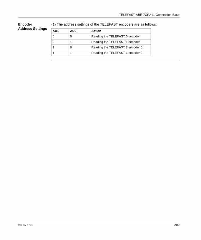
TELEFAST ABE-7CPA11 Connection Base
Encoder Address Settings
(1) The address settings of the TELEFAST encoders are as follows:
AD1 AD0 Action
0 0 Reading the TELEFAST 0 encoder
0 1 Reading the TELEFAST 1 encoder
1 0 Reading the TELEFAST 2 encoder 0
1 1 Reading the TELEFAST 1 encoder 2
TSX DM 37 xx 209
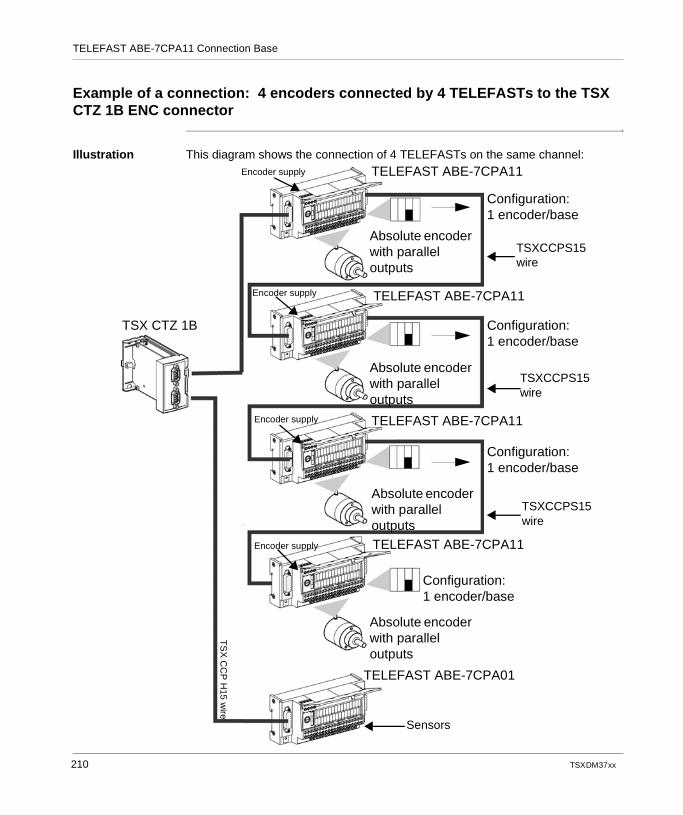
TELEFAST ABE-7CPA11 Connection Base
Example of a connection: 4 encoders connected by 4 TELEFASTs to the TSX CTZ 1B ENC connector
Illustration This diagram shows the connection of 4 TELEFASTs on the same channel: TELEFAST ABE-7CPA11
Absolute encoder with parallel outputs
Configuration:1 encoder/base
Configuration:1 encoder/base
Absolute encoder with parallel outputs
TELEFAST ABE-7CPA11
TELEFAST ABE-7CPA11
TELEFAST ABE-7CPA11
Absolute encoder with parallel outputs
Configuration:1 encoder/base
Configuration:1 encoder/base
Absolute encoder with parallel outputs
TELEFAST ABE-7CPA01
TSX CTZ 1B
TS
X C
CP
H15 w
ire
TSXCCPS15wire
TSXCCPS15wire
TSXCCPS15wire
Sensors
Encoder supply
Encoder supply
Encoder supply
Encoder supply
210 TSX DM 37 xx
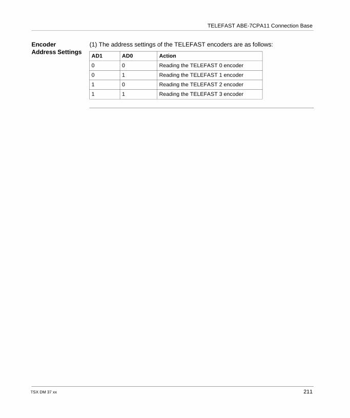
TELEFAST ABE-7CPA11 Connection Base
Encoder Address Settings
(1) The address settings of the TELEFAST encoders are as follows:
AD1 AD0 Action
0 0 Reading the TELEFAST 0 encoder
0 1 Reading the TELEFAST 1 encoder
1 0 Reading the TELEFAST 2 encoder
1 1 Reading the TELEFAST 3 encoder
TSX DM 37 xx 211
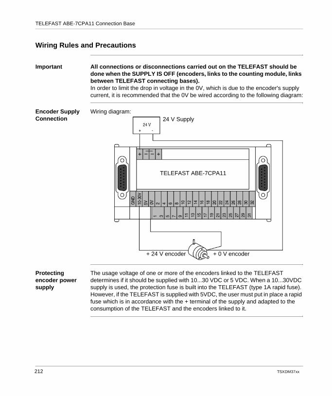
TELEFAST ABE-7CPA11 Connection Base
Wiring Rules and Precautions
Important All connections or disconnections carried out on the TELEFAST should be done when the SUPPLY IS OFF (encoders, links to the counting module, links between TELEFAST connecting bases).In order to limit the drop in voltage in the 0V, which is due to the encoder's supply current, it is recommended that the 0V be wired according to the following diagram:
Encoder Supply Connection
Wiring diagram:
Protecting encoder power supply
The usage voltage of one or more of the encoders linked to the TELEFAST determines if it should be supplied with 10...30 VDC or 5 VDC. When a 10...30VDC supply is used, the protection fuse is built into the TELEFAST (type 1A rapid fuse). However, if the TELEFAST is supplied with 5VDC, the user must put in place a rapid fuse which is in accordance with the + terminal of the supply and adapted to the consumption of the TELEFAST and the encoders linked to it.
TELEFAST ABE-7CPA11
+ 24 V encoder + 0 V encoder
24 V Supply
212 TSX DM 37 xx
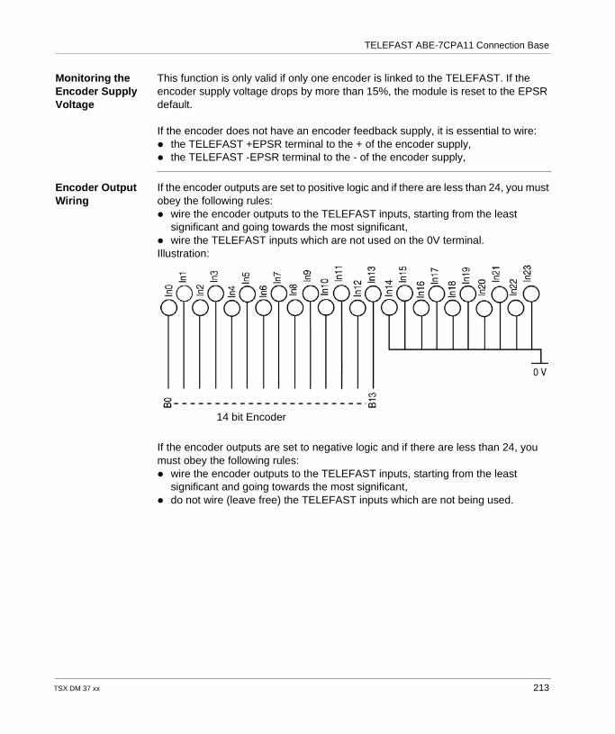
TELEFAST ABE-7CPA11 Connection Base
Monitoring the Encoder Supply Voltage
This function is only valid if only one encoder is linked to the TELEFAST. If the encoder supply voltage drops by more than 15%, the module is reset to the EPSR default.
If the encoder does not have an encoder feedback supply, it is essential to wire: the TELEFAST +EPSR terminal to the + of the encoder supply, the TELEFAST -EPSR terminal to the - of the encoder supply,
Encoder Output Wiring
If the encoder outputs are set to positive logic and if there are less than 24, you must obey the following rules: wire the encoder outputs to the TELEFAST inputs, starting from the least
significant and going towards the most significant, wire the TELEFAST inputs which are not used on the 0V terminal.Illustration:
If the encoder outputs are set to negative logic and if there are less than 24, you must obey the following rules: wire the encoder outputs to the TELEFAST inputs, starting from the least
significant and going towards the most significant, do not wire (leave free) the TELEFAST inputs which are not being used.
14 bit Encoder
TSX DM 37 xx 213
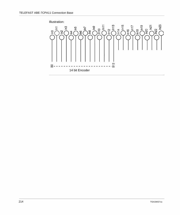
TELEFAST ABE-7CPA11 Connection Base
Illustration:
14 bit Encoder
214 TSX DM 37 xx
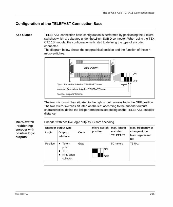
TELEFAST ABE-7CPA11 Connection Base
Configuration of the TELEFAST Connection Base
At a Glance TELEFAST connection base configuration is performed by positioning the 4 micro-switches which are situated under the 15 pin SUB D connector. When using the TSX CTZ 1B module, the configuration is limited to defining the type of encoder connected. The diagram below shows the geographical position and the function of these 4 micro-switches.
The two micro-switches situated to the right should always be in the OFF position. The two micro-switches situated on the left, according to the encoder outputs characteristics, define the link performances depending on the TELEFAST/encoder distance.
Micro-switch Positioning: encoder with positive logic outputs
Encoder with positive logic outputs, GRAY encoding
Number of encoders linked to TELEFAST base
Encoder output inhibition
Type of encoder linked to TELEFAST base
Encoder output type micro-switch position:
Max. length encoder/TELEFAST
Max. frequency of change of the least significant bit
Logic Output interface
Code
Positive Totem pole.
TTL NPN open
collector
Gray 50 meters 75 kHz
TSX DM 37 xx 215
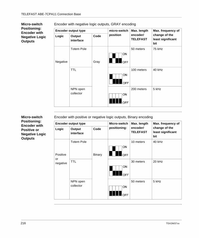
TELEFAST ABE-7CPA11 Connection Base
Micro-switch Positioning: Encoder with Negative Logic Outputs
Encoder with negative logic outputs, GRAY encoding
Micro-switch Positioning: Encoder with Positive or Negative Logic Outputs
Encoder with positive or negative logic outputs, Binary encoding
Encoder output type micro-switch position
Max. length encoder/TELEFAST
Max. frequency of change of the least significant bit
Logic Output interface
Code
Negative
Totem Pole
Gray
50 meters 75 kHz
TTL 100 meters 40 kHz
NPN open collector
200 meters 5 kHz
Encoder output type Micro-switch positioning:
Max. length encoder/TELEFAST
Max. frequency of change of the least significant bit
Logic Output interface
Code
Positive or negative
Totem Pole
Binary
10 meters 40 kHz
TTL 30 meters 20 kHz
NPN open collector
50 meters 5 kHz
216 TSX DM 37 xx
TSX DM 37 xx
IV
Communication via a PCMCIA CardAt a Glance
Aim of this Part This part aims to introduce communication via a PCMCIA card.
What's in this Part?
This part contains the following chapters:
Chapter Chapter Name Page
19 Introduction to PCMCIA Cards 219
20 Implementation of PCMCIA cards 227
21 Connecting the PCMCIA cards 235
22 Communication via a Modem PCMCIA card 265
217

Communication via a PCMCIA Card
218 TSX DM 37 xx
TSX DM 37 xx
19
Introduction to PCMCIA CardsAt a Glance
Aim of this Chapter
This chapter introduces and describes PCMCIA cards, their characteristics and operating norms.
What's in this Chapter?
This chapter contains the following topics:
Topic Page
Introduction to PCMCIA Cards 220
Description of PCMCIA cards 223
Physical features 224
Operational standard 225
Compatibility 226
219
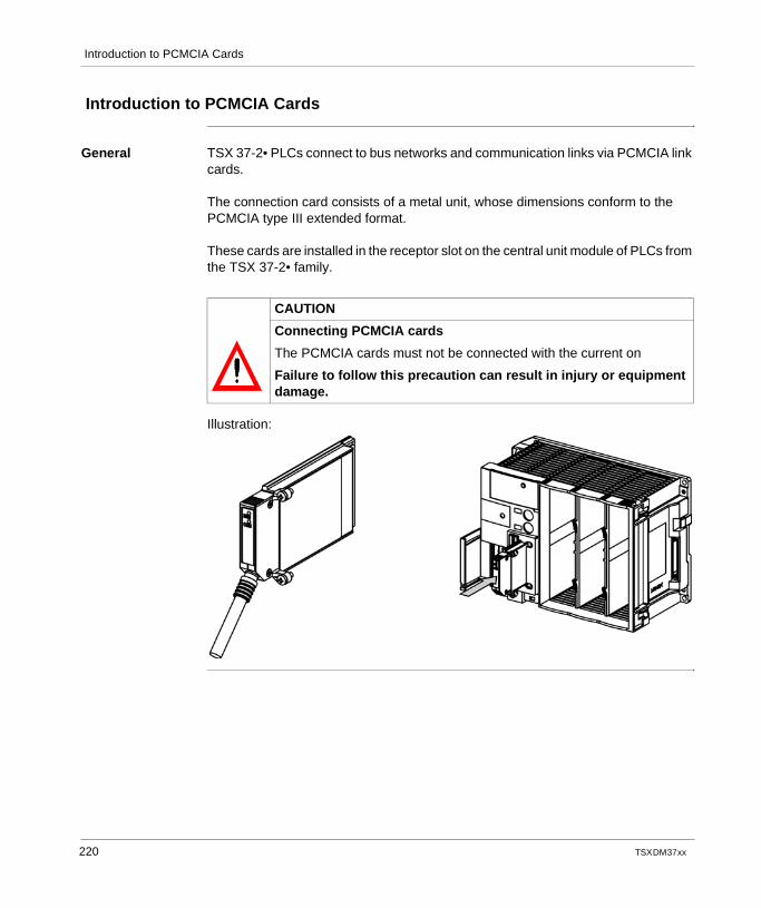
Introduction to PCMCIA Cards
Introduction to PCMCIA Cards
General TSX 37-2• PLCs connect to bus networks and communication links via PCMCIA link cards.
The connection card consists of a metal unit, whose dimensions conform to the PCMCIA type III extended format.
These cards are installed in the receptor slot on the central unit module of PLCs from the TSX 37-2• family.
Illustration:
CAUTION
Connecting PCMCIA cards
The PCMCIA cards must not be connected with the current on
Failure to follow this precaution can result in injury or equipment damage.
220 TSX DM 37 xx
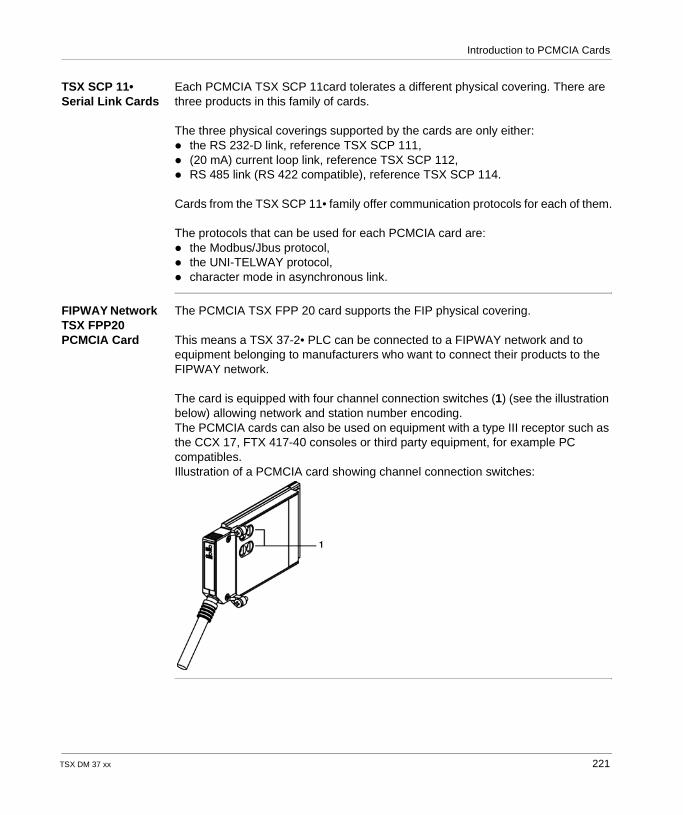
Introduction to PCMCIA Cards
TSX SCP 11• Serial Link Cards
Each PCMCIA TSX SCP 11card tolerates a different physical covering. There are three products in this family of cards.
The three physical coverings supported by the cards are only either: the RS 232-D link, reference TSX SCP 111, (20 mA) current loop link, reference TSX SCP 112, RS 485 link (RS 422 compatible), reference TSX SCP 114.
Cards from the TSX SCP 11• family offer communication protocols for each of them.
The protocols that can be used for each PCMCIA card are: the Modbus/Jbus protocol, the UNI-TELWAY protocol, character mode in asynchronous link.
FIPWAY Network TSX FPP20 PCMCIA Card
The PCMCIA TSX FPP 20 card supports the FIP physical covering.
This means a TSX 37-2• PLC can be connected to a FIPWAY network and to equipment belonging to manufacturers who want to connect their products to the FIPWAY network.
The card is equipped with four channel connection switches (1) (see the illustration below) allowing network and station number encoding.The PCMCIA cards can also be used on equipment with a type III receptor such as the CCX 17, FTX 417-40 consoles or third party equipment, for example PC compatibles.Illustration of a PCMCIA card showing channel connection switches:
TSX DM 37 xx 221

Introduction to PCMCIA Cards
FIPIO Bus Agent TSX FPP10 PCMCIA Card
A PCMCIA TSX FPP 10 card allows a TSX 37 PLC to connect to a FIPIO bus as a FIPIO agent. It ensures a link to the TSX 47-107 and April 5000 PLCs.Illustration:
Modbus + Network Card
A PCMCIA TSX MBP 100 card allows a TSX 37-2• PLC to connect to a Modbus + network. It ensures a link with Modicon type PLCs.
Note: PCMCIA cards are implemented, operated and maintained with the help of PL7 Micro or PL7 Junior programming and operation software for TSX 37 PLCs.
222 TSX DM 37 xx
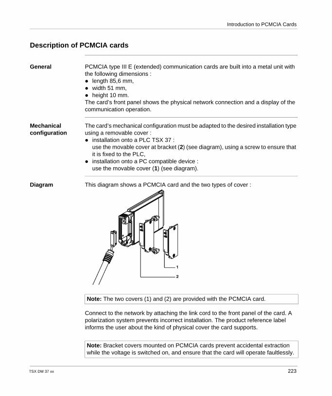
Introduction to PCMCIA Cards
Description of PCMCIA cards
General PCMCIA type III E (extended) communication cards are built into a metal unit with the following dimensions : length 85,6 mm, width 51 mm, height 10 mm.The card’s front panel shows the physical network connection and a display of the communication operation.
Mechanical configuration
The card’s mechanical configuration must be adapted to the desired installation type using a removable cover : installation onto a PLC TSX 37 :
use the movable cover at bracket (2) (see diagram), using a screw to ensure that it is fixed to the PLC,
installation onto a PC compatible device :use the movable cover (1) (see diagram).
Diagram This diagram shows a PCMCIA card and the two types of cover :
Connect to the network by attaching the link cord to the front panel of the card. A polarization system prevents incorrect installation. The product reference label informs the user about the kind of physical cover the card supports.
Note: The two covers (1) and (2) are provided with the PCMCIA card.
Note: Bracket covers mounted on PCMCIA cards prevent accidental extraction while the voltage is switched on, and ensure that the card will operate faultlessly.
TSX DM 37 xx 223
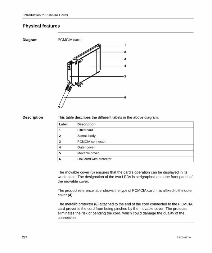
Introduction to PCMCIA Cards
Physical features
Diagram PCMCIA card :
Description This table describes the different labels in the above diagram:
The movable cover (5) ensures that the card’s operation can be displayed in its workspace. The designation of the two LEDs is serigraphed onto the front panel of the movable cover.
The product reference label shows the type of PCMCIA card. It is affixed to the outer cover (4).
The metallic protector (6) attached to the end of the cord connected to the PCMCIA card prevents the cord from being pinched by the movable cover. The protector eliminates the risk of bending the cord, which could damage the quality of the connection.
Label Description
1 Fitted card.
2 Zamak body.
3 PCMCIA connector.
4 Outer cover.
5 Movable cover.
6 Link cord with protector.
224 TSX DM 37 xx
Introduction to PCMCIA Cards
Operational standard
General PCMCIA cards connected to a TSX 37 conform to the standards of usage referred to below, according to the applicable country.: US Standards : UL508, CEI 1131-2, Canadian Standard : CSA C22.2/142, CEI 1131, Conforms to rules : FCC-B, EC labeling Standard PCMCIA, mechanical type III E, PCMCIA 2.01, Marine VB (Veritas) DNV, GL, LROS, Petrochemistry FM, Energy EDF, ENEL.
The protection index for PCMCIA cards is PI = 40.
The PCMCIA FIPWAY TSX FPP 20 cards and FIPIO agent TSX FPP 10 conform to the following communication standards : the FIP protocol (connection, network management), the PCMCIA standard, the XWAY communication standard.
The PCMCIA TSX SCP 111, 112, 114 cards conform to the following communication standards : the UNI-TELWAY, MODBUS protocol (connection, network management), the PCMCIA standard, the XWAY communication standard.
TSX DM 37 xx 225
Introduction to PCMCIA Cards
Compatibility
General The PCMCIA TSX SCP 111/112/114 cards ensure communication with TSX 7, 1000 series, and Modicon PLCs, aswell as other products compatible to UNIT-TELWAY, MODBUS and character mode. PCMCIA cards are also MODBUS/JBUS compatible with series 1000 PLCs.
The TSX FPP 20 FIPWAY card is compatible with the following FIPWAY devices : Model 40 PLCs (TSX 47-455, TSX 67-455…) with more recent versions than 5.0, PLC TSX 17, Compatible PCs connected using TSX FPP10 and TSX FPP20 cards.
226 TSX DM 37 xx
TSX DM 37 xx
20
Implementation of PCMCIA cardsAt a Glance
Aim of this chapter
This chapter deals with the implementation of PCMCIA cards.
What's in this Chapter?
This chapter contains the following topics:
Topic Page
Installing cards and cords for the TSX 37-2• 228
PCMCIA card references 229
PCMCIA card operational display 230
Visual diagnostics of the PCMCIA card 231
227
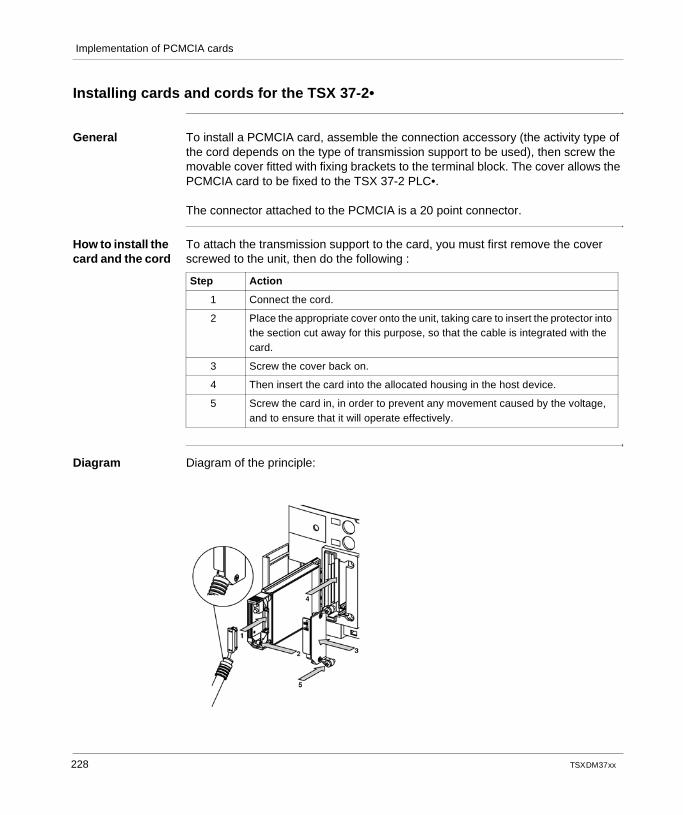
Implementation of PCMCIA cards
Installing cards and cords for the TSX 37-2•
General To install a PCMCIA card, assemble the connection accessory (the activity type of the cord depends on the type of transmission support to be used), then screw the movable cover fitted with fixing brackets to the terminal block. The cover allows the PCMCIA card to be fixed to the TSX 37-2 PLC•.
The connector attached to the PCMCIA is a 20 point connector.
How to install the card and the cord
To attach the transmission support to the card, you must first remove the cover screwed to the unit, then do the following :
Diagram Diagram of the principle:
Step Action
1 Connect the cord.
2 Place the appropriate cover onto the unit, taking care to insert the protector into the section cut away for this purpose, so that the cable is integrated with the card.
3 Screw the cover back on.
4 Then insert the card into the allocated housing in the host device.
5 Screw the card in, in order to prevent any movement caused by the voltage, and to ensure that it will operate effectively.
228 TSX DM 37 xx
Implementation of PCMCIA cards
PCMCIA card references
General The PCMCIA card references are as follows : TSX SCP 111 : multiprotocol card RS 232 D, 9 non isolated signals, TSX SCP 112 : multiprotocol card current loop 20 mA, TSX SCP 114 : multiprotocol card RS 485 compatible RS 422 remote, TSX FPP 20 : FIPWAY network card, TSX FPP 10 : FIPIO Agent bus card, TSX MBP 100 : Modbus + network card.
TSX DM 37 xx 229
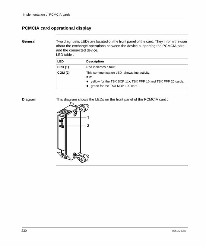
Implementation of PCMCIA cards
PCMCIA card operational display
General Two diagnostic LEDs are located on the front panel of the card. They inform the user about the exchange operations between the device supporting the PCMCIA card and the connected device.LED table :
Diagram This diagram shows the LEDs on the front panel of the PCMCIA card :
LED Description
ERR (1) Red indicates a fault.
COM (2) This communication LED shows line activity.It is: yellow for the TSX SCP 11•, TSX FPP 10 and TSX FPP 20 cards, green for the TSX MBP 100 card.
230 TSX DM 37 xx
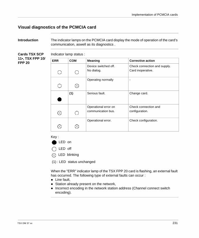
Implementation of PCMCIA cards
Visual diagnostics of the PCMCIA card
Introduction The indicator lamps on the PCMCIA card display the mode of operation of the card’s communication, aswell as its diagnostics .
Cards TSX SCP 11•, TSX FPP 10/FPP 20
Indicator lamp status :
Key :
When the "ERR" indicator lamp of the TSX FPP 20 card is flashing, an external fault has occurred. The following type of external faults can occur : Line fault, Station already present on the network, Incorrect encoding in the network station address (Channel connect switch
encoding).
ERR COM Meaning Corrective action
Device switched off.No dialog.
Check connection and supply.Card inoperative.
Operating normally -
(1) Serious fault. Change card.
Operational error on communication bus.
Check connection and configuration.
Operational error. Check configuration.
LED on
LED off
LED blinking
(1) : LED status unchanged
TSX DM 37 xx 231
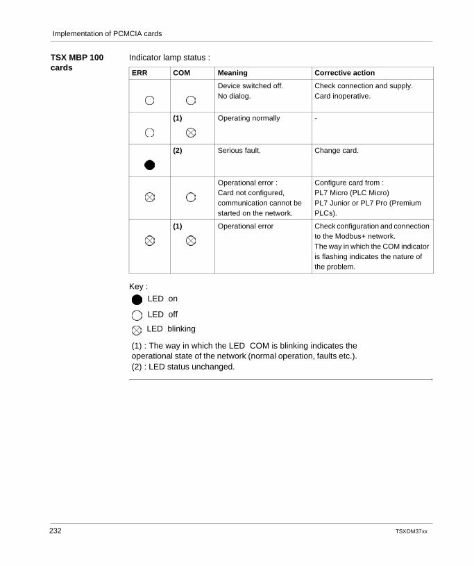
Implementation of PCMCIA cards
TSX MBP 100 cards
Indicator lamp status :
Key :
ERR COM Meaning Corrective action
Device switched off.No dialog.
Check connection and supply.Card inoperative.
(1) Operating normally -
(2) Serious fault. Change card.
Operational error :Card not configured, communication cannot be started on the network.
Configure card from :PL7 Micro (PLC Micro)PL7 Junior or PL7 Pro (Premium PLCs).
(1) Operational error Check configuration and connection to the Modbus+ network.The way in which the COM indicator is flashing indicates the nature of the problem.
LED on
LED off
LED blinking
(1) : The way in which the LED COM is blinking indicates theoperational state of the network (normal operation, faults etc.).(2) : LED status unchanged.
232 TSX DM 37 xx
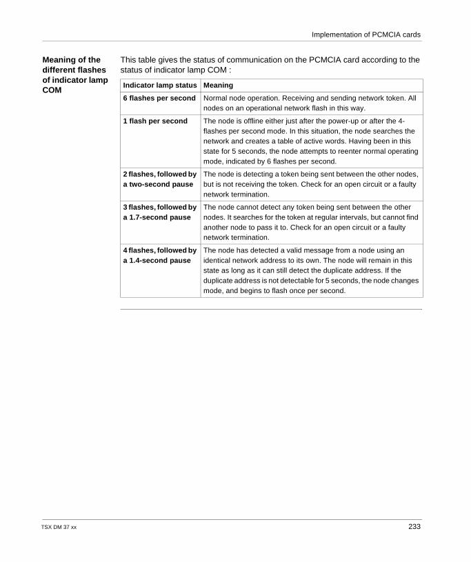
Implementation of PCMCIA cards
Meaning of the different flashes of indicator lamp COM
This table gives the status of communication on the PCMCIA card according to the status of indicator lamp COM :
Indicator lamp status Meaning
6 flashes per second Normal node operation. Receiving and sending network token. All nodes on an operational network flash in this way.
1 flash per second The node is offline either just after the power-up or after the 4-flashes per second mode. In this situation, the node searches the network and creates a table of active words. Having been in this state for 5 seconds, the node attempts to reenter normal operating mode, indicated by 6 flashes per second.
2 flashes, followed by a two-second pause
The node is detecting a token being sent between the other nodes, but is not receiving the token. Check for an open circuit or a faulty network termination.
3 flashes, followed by a 1.7-second pause
The node cannot detect any token being sent between the other nodes. It searches for the token at regular intervals, but cannot find another node to pass it to. Check for an open circuit or a faulty network termination.
4 flashes, followed by a 1.4-second pause
The node has detected a valid message from a node using an identical network address to its own. The node will remain in this state as long as it can still detect the duplicate address. If the duplicate address is not detectable for 5 seconds, the node changes mode, and begins to flash once per second.
TSX DM 37 xx 233

Implementation of PCMCIA cards
234 TSX DM 37 xx
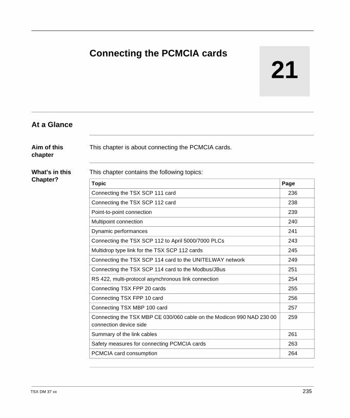
TSX DM 37 xx
21
Connecting the PCMCIA cardsAt a Glance
Aim of this chapter
This chapter is about connecting the PCMCIA cards.
What's in this Chapter?
This chapter contains the following topics:
Topic Page
Connecting the TSX SCP 111 card 236
Connecting the TSX SCP 112 card 238
Point-to-point connection 239
Multipoint connection 240
Dynamic performances 241
Connecting the TSX SCP 112 to April 5000/7000 PLCs 243
Multidrop type link for the TSX SCP 112 cards 245
Connecting the TSX SCP 114 card to the UNITELWAY network 249
Connecting the TSX SCP 114 card to the Modbus/JBus 251
RS 422, multi-protocol asynchronous link connection 254
Connecting TSX FPP 20 cards 255
Connecting TSX FPP 10 card 256
Connecting TSX MBP 100 card 257
Connecting the TSX MBP CE 030/060 cable on the Modicon 990 NAD 230 00 connection device side
259
Summary of the link cables 261
Safety measures for connecting PCMCIA cards 263
PCMCIA card consumption 264
235
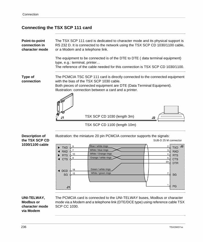
Connection
Connecting the TSX SCP 111 card
Point-to-point connection in character mode
The TSX SCP 111 card is dedicated to character mode and its physical support is RS 232 D. It is connected to the network using the TSX SCP CD 1030/1100 cable, or a Modem and a telephone link.
The equipment to be connected is of the DTE to DTE ( data terminal equipment) type, e.g.: terminal, printer…The reference of the cable needed for this connection is TSX SCP CD 1030/1100.
Type of connection
The PCMCIA TSC SCP 111 card is directly connected to the connected equipment with the bias of the TSX SCP 1030 cable.Both pieces of connected equipment are DTE (Data Terminal Equipment).Illustration: connection between a card and a printer.
Description of the TSX SCP CD 1030/1100 cable
Illustration: the miniature 20 pin PCMCIA connector supports the signals:
UNI-TELWAY, Modbus or character mode via Modem
The PCMCIA card is connected to the UNI-TELWAY buses, Modbus or character mode via a Modem and a telephone link (DTE/DCE type) using reference cable TSX SCP CC 1030.
TSX SCP CD 1030 (length 3m)
TSX SCP CD 1100 (length 10m)
SUB-D 25 M connector
Blue / white rings
White / blue rings
White / Orange rings
Orange / white rings
Green / white rings
White / green rings
236 TSX DM 37 xx
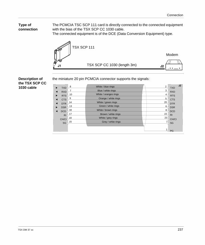
Connection
Type of connection
The PCMCIA TSC SCP 111 card is directly connected to the connected equipment with the bias of the TSX SCP CC 1030 cable.The connected equipment is of the DCE (Data Conversion Equipment) type.
Description of the TSX SCP CC 1030 cable
the miniature 20 pin PCMCIA connector supports the signals:
TSX SCP 111
Modem
TSX SCP CC 1030 (length 3m)
SG
CH/CI
RI
DCD
DSR
DTR
CTS
RTS
RXD
TXD
J1
8
7
10
9
14
13
18
17
19
15CH/CI
DTR
CTS
RTS
RXD
TXD
PG
SG
RI
DSR
DCD
J2
1
7
23
22
8
6
20
5
4
3
2White / blue rings
Blue / white rings
White / oranges rings
Orange / white rings
White / green rings
Green / white rings
White / brown rings
Brown / white rings
White / grey rings
Grey / white rings
TSX DM 37 xx 237
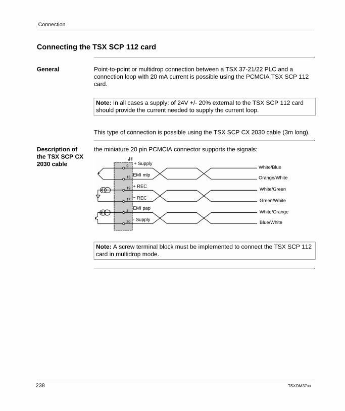
Connection
Connecting the TSX SCP 112 card
General Point-to-point or multidrop connection between a TSX 37-21/22 PLC and a connection loop with 20 mA current is possible using the PCMCIA TSX SCP 112 card.
This type of connection is possible using the TSX SCP CX 2030 cable (3m long).
Description of the TSX SCP CX 2030 cable
the miniature 20 pin PCMCIA connector supports the signals:
Note: In all cases a supply: of 24V +/- 20% external to the TSX SCP 112 card should provide the current needed to supply the current loop.
Note: A screw terminal block must be implemented to connect the TSX SCP 112 card in multidrop mode.
White/Blue
Orange/White
White/Green
Green/White
White/Orange
Blue/White
+ Supply
EMI mlp
+ REC
- REC
EMI pap
- Supply
238 TSX DM 37 xx
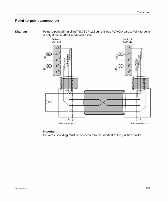
Connection
Point-to-point connection
Diagram Point-to-point wiring of the TSX SCP 112 current loop PCMCIA cards. Point-to-point is only done in 20mA mode when idle.
Important:the wires’ shielding must be connected to the shortest of the junction blocks.
Whi
te/O
rang
eG
reen
/Whi
teW
hite
/Gre
enW
hite
/Blu
eB
lue/
Whi
te
Whi
te/O
rang
eG
reen
/Whi
teW
hite
/Gre
enW
hite
/Blu
eB
lue/
Whi
te
Function block 1 Function block 2
Station 1SCP 112
Station 2SCP 112
TSX DM 37 xx 239
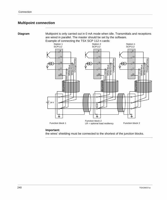
Connection
Multipoint connection
Diagram Multipoint is only carried out in 0 mA mode when idle. Transmittals and receptions are wired in parallel. The master should be set by the software.Example of connecting the TSX SCP 112 n cards:
Important:the wires’ shielding must be connected to the shortest of the junction blocks.
Blu
e/W
hite G
reen
/Whi
teW
hite
/Blu
eW
hite
/Gre
enO
rang
e/W
hite
Blu
e/W
hite G
reen
/Whi
teW
hite
/Blu
eW
hite
/Gre
enO
rang
e/W
hite
Blu
e/W
hite G
reen
/Whi
teW
hite
/Blu
eW
hite
/Gre
enO
rang
e/W
hite
Function block 1Function block 2LR = optional load resiliency Function block 2
Station 1SCP112
Station 2SCP112
Station nSCP112
240 TSX DM 37 xx
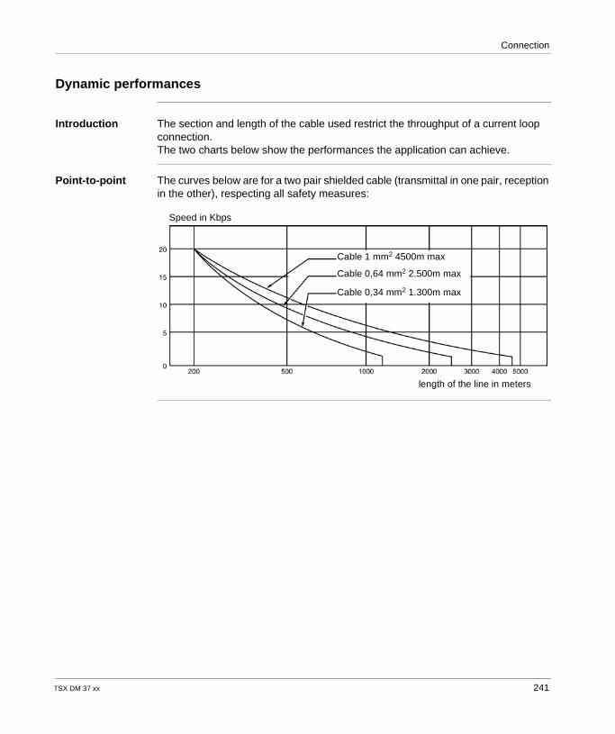
Connection
Dynamic performances
Introduction The section and length of the cable used restrict the throughput of a current loop connection.The two charts below show the performances the application can achieve.
Point-to-point The curves below are for a two pair shielded cable (transmittal in one pair, reception in the other), respecting all safety measures:
Cable 1 mm2 4500m max
Cable 0,64 mm2 2.500m max
Cable 0,34 mm2 1.300m max
Speed in Kbps
length of the line in meters
TSX DM 37 xx 241
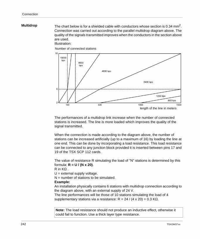
Connection
Multidrop The chart below is for a shielded cable with conductors whose section is 0.34 mm2. Connection was carried out according to the parallel multidrop diagram above. The quality of the signals transmitted improves when the conductors in the section above are used.Illustration:
The performances of a multidrop link increase when the number of connected stations is increased. The line is more loaded which improves the quality of the signal transmitted.
When the connection is made according to the diagram above, the number of stations can be increased artificially (up to a maximum of 16) by loading the line at one end. This can be done by incorporating a load resistance. This load resistance can be connected to any junction block provided it is inserted between pins 17 and 19 of the TSX SCP 112 cards.
The value of resistance R simulating the load of "N" stations is determined by this formula: R = U / (N x 20).R in KΩ .U = external supply voltage.N = number of stations to be simulated.Example:An installation physically contains 6 stations with multidrop connection according to the diagram above, with an external supply of 24 V.The line performances will be those of 10 stations simulating the load of 4 supplementary stations via a resistance: R = 24 / (4 x 20) = 0.3 KΩ.
Note: The load resistance should not produce an inductive effect, otherwise it could fail to function. Use a thick layer type resistance.
Number of connected stations
length of the line in meters
242 TSX DM 37 xx
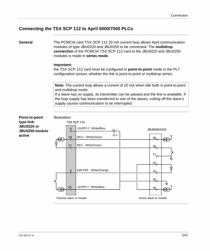
Connection
Connecting the TSX SCP 112 to April 5000/7000 PLCs
General The PCMCIA card TSX SCP 112 20 mA current loop allows April communication modules of type JBU0220 and JBU0250 to be connected. The multidrop connection of the PCMCIA TSX SCP 112 card to the JBU0220 and JBU0250 modules is made in series mode.
Important:the TSX SCP 112 card must be configured in point-to-point mode in the PL7 configuration screen, whether the link is point-to-point or multidrop series.
Point-to-point type link: JBU0220 or JBU0250 module active
Illustration:
Note: The current loop allows a current of 20 mA when idle both in point-to-point and multidrop mode.If a slave has no supply, its transmitter can be passed and the line is available. If the loop supply has been transferred to one of the slaves, cutting off the slave’s supply causes communication to be interrupted.
Passive slave or master Active slave or master
+SUPPLY White/Blue
REC+ White/Green
REC- White/Green
EMI PAP White/Orange
-SUPPLY White/Blue
TSX DM 37 xx 243
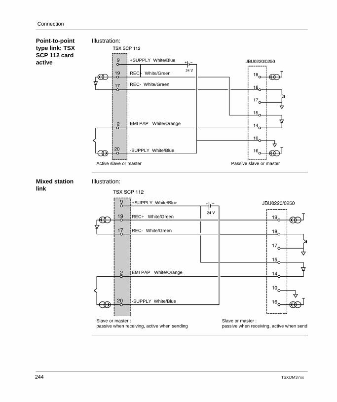
Connection
Point-to-point type link: TSX SCP 112 card active
Illustration:
Mixed station link
Illustration:
+SUPPLY White/Blue
REC+ White/Green
REC- White/Green
EMI PAP White/Orange
-SUPPLY White/Blue
Active slave or master Passive slave or master
+SUPPLY White/Blue
REC+ White/Green
REC- White/Green
EMI PAP White/Orange
-SUPPLY White/Blue
Slave or master :passive when receiving, active when sending
Slave or master :passive when receiving, active when send
244 TSX DM 37 xx
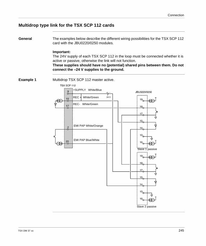
Connection
Multidrop type link for the TSX SCP 112 cards
General The examples below describe the different wiring possibilities for the TSX SCP 112 card with the JBU0220/0250 modules.
Important:The 24V supply of each TSX SCP 112 in the loop must be connected whether it is active or passive, otherwise the link will not function.These supplies should have no (potential) shared pins between them. Do not connect the –24 V supplies to the ground.
Example 1 Multidrop TSX SCP 112 master active.
+SUPPLY White/Blue
REC + White/Green
REC- White/Green
EMI PAP White/Orange
EMI PAP Blue/White
Slave 1 passive
Slave 2 passive
TSX DM 37 xx 245
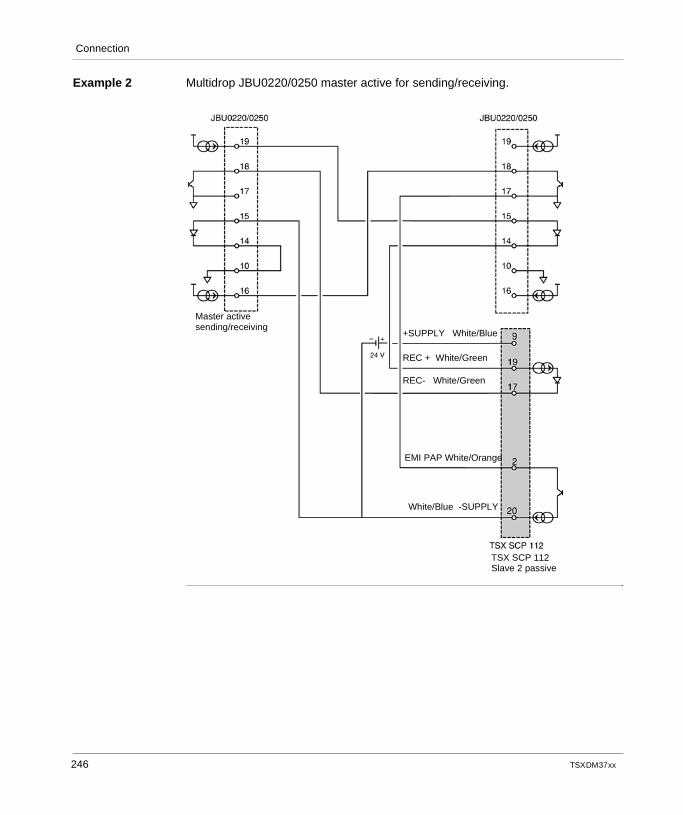
Connection
Example 2 Multidrop JBU0220/0250 master active for sending/receiving.
+SUPPLY White/Blue
REC + White/Green
REC- White/Green
EMI PAP White/Orange
White/Blue -SUPPLY
Master activesending/receiving
TSX SCP 112Slave 2 passive
246 TSX DM 37 xx
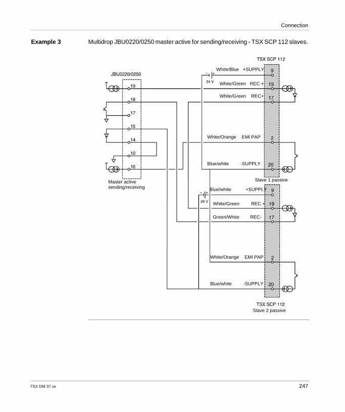
Connection
Example 3 Multidrop JBU0220/0250 master active for sending/receiving - TSX SCP 112 slaves.
White/Blue +SUPPLY
White/Green REC +
White/Orange EMI PAP
Blue/white -SUPPLY
Blue/white +SUPPLY
White/Green REC +
Green/White REC-
White/Orange EMI PAP
Blue/white -SUPPLY
Slave 2 passive
Master activesending/receiving
White/Green REC+
Slave 1 passive
TSX DM 37 xx 247
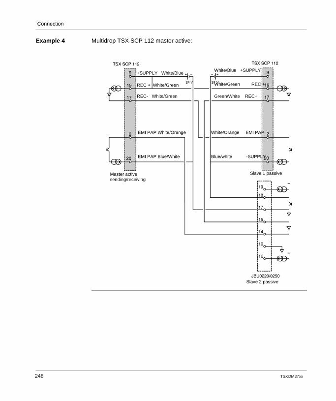
Connection
Example 4 Multidrop TSX SCP 112 master active:
White/Blue +SUPPLY
White/Green REC +
Green/White REC+
White/Orange EMI PAP
Blue/white -SUPPLY
Master activesending/receiving
Slave 2 passive
Slave 1 passive
+SUPPLY White/Blue
REC + White/Green
REC- White/Green
EMI PAP White/Orange
EMI PAP Blue/White
248 TSX DM 37 xx
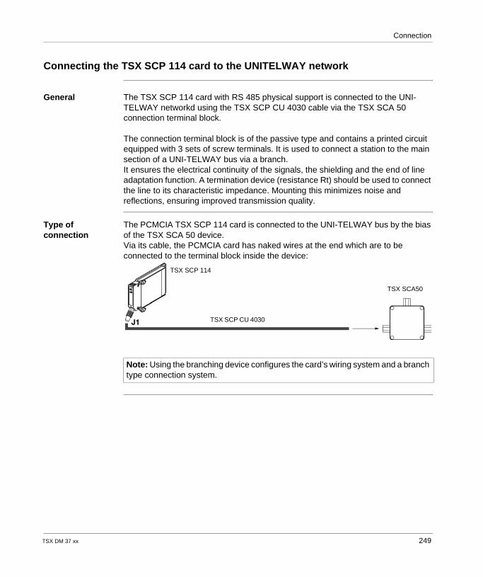
Connection
Connecting the TSX SCP 114 card to the UNITELWAY network
General The TSX SCP 114 card with RS 485 physical support is connected to the UNI-TELWAY networkd using the TSX SCP CU 4030 cable via the TSX SCA 50 connection terminal block.
The connection terminal block is of the passive type and contains a printed circuit equipped with 3 sets of screw terminals. It is used to connect a station to the main section of a UNI-TELWAY bus via a branch.It ensures the electrical continuity of the signals, the shielding and the end of line adaptation function. A termination device (resistance Rt) should be used to connect the line to its characteristic impedance. Mounting this minimizes noise and reflections, ensuring improved transmission quality.
Type of connection
The PCMCIA TSX SCP 114 card is connected to the UNI-TELWAY bus by the bias of the TSX SCA 50 device.Via its cable, the PCMCIA card has naked wires at the end which are to be connected to the terminal block inside the device:
Note: Using the branching device configures the card’s wiring system and a branch type connection system.
TSX SCP 114
TSX SCP CU 4030
TSX SCA50
TSX DM 37 xx 249
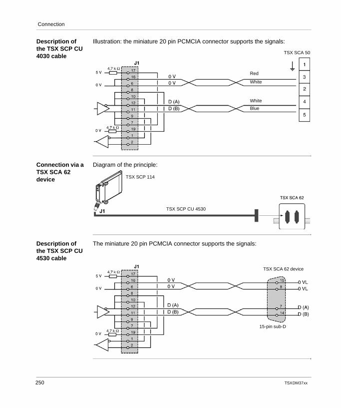
Connection
Description of the TSX SCP CU 4030 cable
Illustration: the miniature 20 pin PCMCIA connector supports the signals:
Connection via a TSX SCA 62 device
Diagram of the principle:
Description of the TSX SCP CU 4530 cable
The miniature 20 pin PCMCIA connector supports the signals:
Red
White
White
Blue
TSX SCA 50
TSX SCP 114
TSX SCP CU 4530
15-pin sub-D
TSX SCA 62 device
250 TSX DM 37 xx
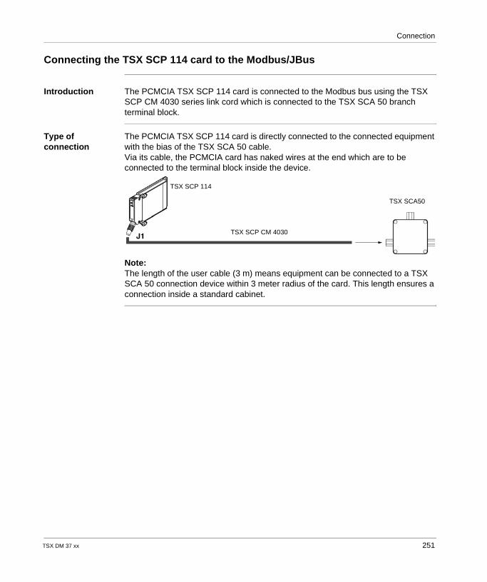
Connection
Connecting the TSX SCP 114 card to the Modbus/JBus
Introduction The PCMCIA TSX SCP 114 card is connected to the Modbus bus using the TSX SCP CM 4030 series link cord which is connected to the TSX SCA 50 branch terminal block.
Type of connection
The PCMCIA TSX SCP 114 card is directly connected to the connected equipment with the bias of the TSX SCA 50 cable.Via its cable, the PCMCIA card has naked wires at the end which are to be connected to the terminal block inside the device.
Note:The length of the user cable (3 m) means equipment can be connected to a TSX SCA 50 connection device within 3 meter radius of the card. This length ensures a connection inside a standard cabinet.
TSX SCP 114
TSX SCA50
TSX SCP CM 4030
TSX DM 37 xx 251
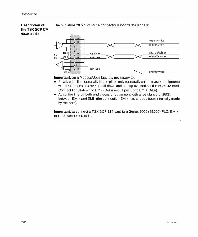
Connection
Description of the TSX SCP CM 4030 cable
The miniature 20 pin PCMCIA connector supports the signals:
Important: on a Modbus/Jbus bus it is necessary to: Polarize the line, generally in one place only (generally on the master equipment)
with resistances of 470Ω of pull-down and pull-up available of the PCMCIA card. Connect R pull-down to EMI- (D(A)) and R pull-up to EMI+(D(B)).
Adapt the line on both end pieces of equipment with a resistance of 150Ω between EMI+ and EMI- (the connection EMI+ has already been internally made by the card).
Important: to connect a TSX SCP 114 card to a Series 1000 (S1000) PLC, EMI+ must be connected to L-.
Green/White
White/Green
Orange/WhiteWhite/Orange
Brown/White
252 TSX DM 37 xx
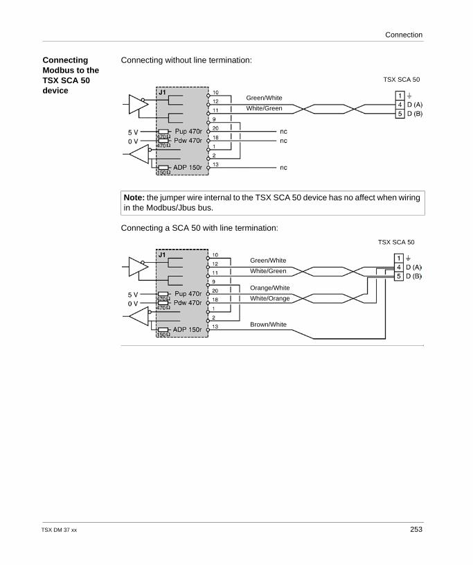
Connection
Connecting Modbus to the TSX SCA 50 device
Connecting without line termination:
Connecting a SCA 50 with line termination:
Note: the jumper wire internal to the TSX SCA 50 device has no affect when wiring in the Modbus/Jbus bus.
TSX SCA 50
Green/White
White/Green
TSX SCA 50
Green/White
White/Green
Orange/White
White/Orange
Brown/White
TSX DM 37 xx 253
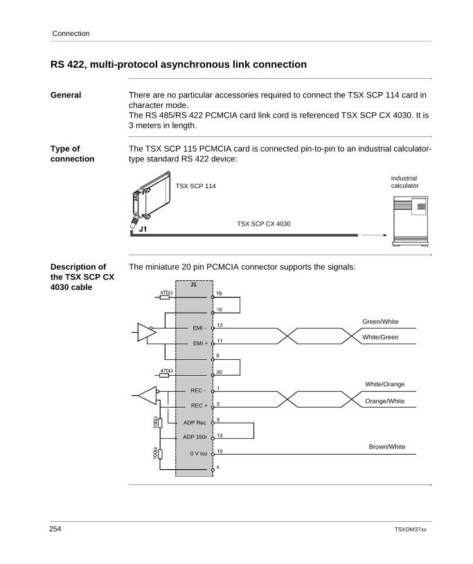
Connection
RS 422, multi-protocol asynchronous link connection
General There are no particular accessories required to connect the TSX SCP 114 card in character mode.The RS 485/RS 422 PCMCIA card link cord is referenced TSX SCP CX 4030. It is 3 meters in length.
Type of connection
The TSX SCP 115 PCMCIA card is connected pin-to-pin to an industrial calculator-type standard RS 422 device:
Description of the TSX SCP CX 4030 cable
The miniature 20 pin PCMCIA connector supports the signals:
TSX SCP 114
TSX SCP CX 4030
industrialcalculator
Green/White
White/Green
White/Orange
Orange/White
Brown/White
J1
EMI -
EMI +
REC -
REC +
ADP Rec
ADP 150r
0 V iso
254 TSX DM 37 xx
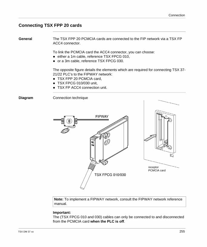
Connection
Connecting TSX FPP 20 cards
General The TSX FPP 20 PCMCIA cards are connected to the FIP network via a TSX FP ACC4 connector.
To link the PCMCIA card the ACC4 connector, you can choose: either a 1m cable, reference TSX FPCG 010, or a 3m cable, reference TSX FPCG 030.
The opposite figure details the elements which are required for connecting TSX 37-21/22 PLC’s to the FIPWAY network: TSX FPP 20 PCMCIA card, TSX FPCG 010/030 unit, TSX FP ACC4 connection unit.
Diagram Connection technique
Important:The (TSX FPCG 010 and 030) cables can only be connected to and disconnected from the PCMCIA card when the PLC is off.
Note: To implement a FIPWAY network, consult the FIPWAY network reference manual.
receptorPCMCIA card
TSX DM 37 xx 255
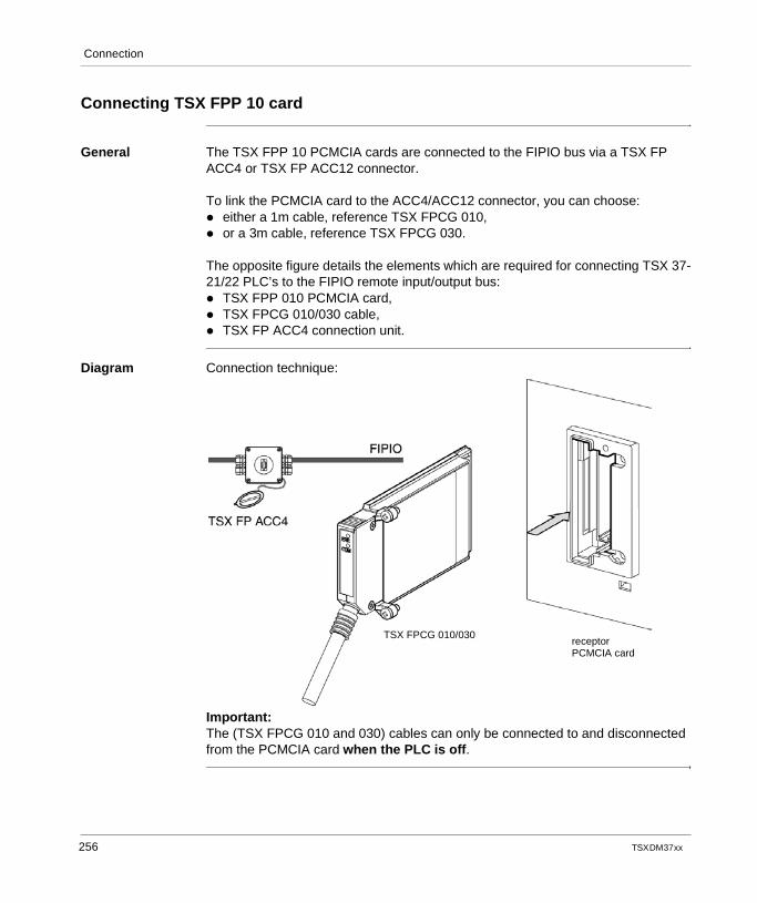
Connection
Connecting TSX FPP 10 card
General The TSX FPP 10 PCMCIA cards are connected to the FIPIO bus via a TSX FP ACC4 or TSX FP ACC12 connector.
To link the PCMCIA card to the ACC4/ACC12 connector, you can choose: either a 1m cable, reference TSX FPCG 010, or a 3m cable, reference TSX FPCG 030.
The opposite figure details the elements which are required for connecting TSX 37-21/22 PLC’s to the FIPIO remote input/output bus: TSX FPP 010 PCMCIA card, TSX FPCG 010/030 cable, TSX FP ACC4 connection unit.
Diagram Connection technique:
Important:The (TSX FPCG 010 and 030) cables can only be connected to and disconnected from the PCMCIA card when the PLC is off.
receptorPCMCIA card
TSX FPCG 010/030
256 TSX DM 37 xx
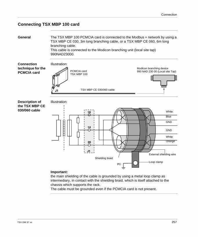
Connection
Connecting TSX MBP 100 card
General The TSX MBP 100 PCMCIA card is connected to the Modbus + network by using a TSX MBP CE 030, 3m long branching cable, or a TSX MBP CE 060, 6m long branching cable.This cable is connected to the Modicon branching unit (local site tap) 990NAD23000.
Connection technique for the PCMCIA card
Illustration:
Description of the TSX MBP CE 030/060 cable
Illustration:
Important:the main shielding of the cable is grounded by using a metal loop clamp as intermediary, in contact with the shielding braid, which is itself attached to the chassis which supports the rack.The cable must be grounded even if the PCMCIA card is not present.
PCMCIA cardTSX MBP 100
TSX MBP CE 030/060 cable
Modicon branching device990 NAD 230 00 (Local site Tap)
White
Blue
GND
GND
White
Orange
External shielding wire
Loop clampShielding braid
TSX DM 37 xx 257
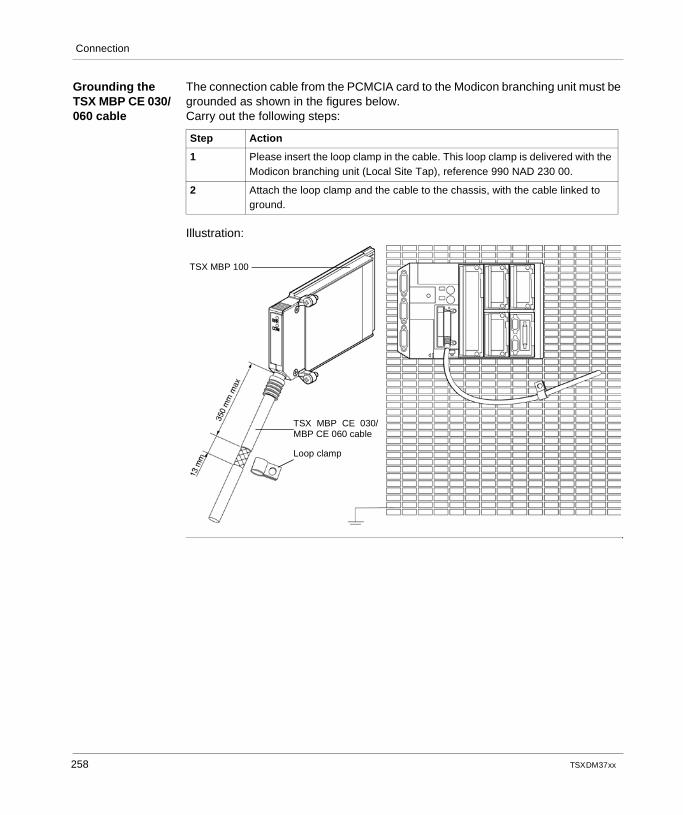
Connection
Grounding the TSX MBP CE 030/060 cable
The connection cable from the PCMCIA card to the Modicon branching unit must be grounded as shown in the figures below.Carry out the following steps:
Illustration:
Step Action
1 Please insert the loop clamp in the cable. This loop clamp is delivered with the Modicon branching unit (Local Site Tap), reference 990 NAD 230 00.
2 Attach the loop clamp and the cable to the chassis, with the cable linked to ground.
TSX MBP 100
TSX MBP CE 030/MBP CE 060 cable
Loop clamp
258 TSX DM 37 xx
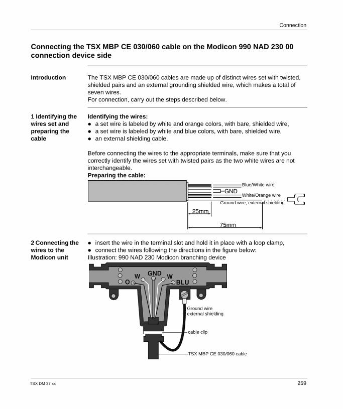
Connection
Connecting the TSX MBP CE 030/060 cable on the Modicon 990 NAD 230 00 connection device side
Introduction The TSX MBP CE 030/060 cables are made up of distinct wires set with twisted, shielded pairs and an external grounding shielded wire, which makes a total of seven wires.For connection, carry out the steps described below.
1 Identifying the wires set and preparing the cable
Identifying the wires: a set wire is labeled by white and orange colors, with bare, shielded wire, a set wire is labeled by white and blue colors, with bare, shielded wire, an external shielding cable.
Before connecting the wires to the appropriate terminals, make sure that you correctly identify the wires set with twisted pairs as the two white wires are not interchangeable.Preparing the cable:
2 Connecting the wires to the Modicon unit
insert the wire in the terminal slot and hold it in place with a loop clamp, connect the wires following the directions in the figure below:Illustration: 990 NAD 230 Modicon branching device
Blue/White wire
White/Orange wire
Ground wire, external shielding
Ground wireexternal shielding
cable clip
TSX MBP CE 030/060 cable
TSX DM 37 xx 259
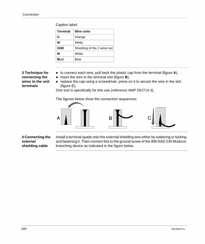
Connection
Caption label:
3 Technique for connecting the wires to the unit terminals
to connect each wire, pull back the plastic cap from the terminal (figure A), insert the wire in the terminal slot (figure B), replace the cap using a screwdriver, press on it to secure the wire in the slot
(figure C).One tool is specifically for this use (reference AMP 552714-3).
The figures below show the connection sequences:
4 Connecting the external shielding cable
Install a terminal spade onto the external shielding wire either by soldering or tacking and fastening it. Then connect this to the ground screw of the 990 NAD 230 Modicon branching device as indicated in the figure below.
Terminal Wire color
O Orange
W White
GND Shielding of the 2 wires set
W White
BLU Blue
260 TSX DM 37 xx
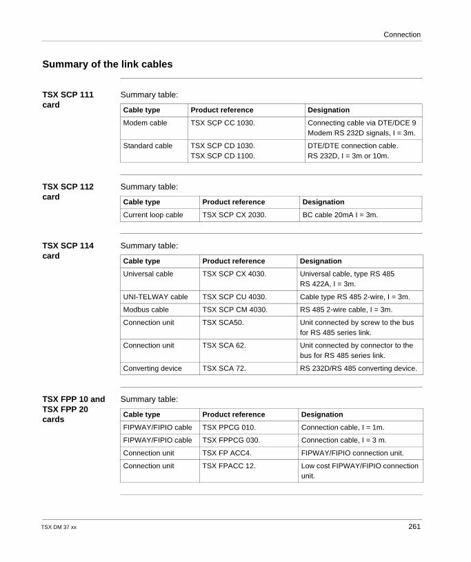
Connection
Summary of the link cables
TSX SCP 111 card
Summary table:
TSX SCP 112 card
Summary table:
TSX SCP 114 card
Summary table:
TSX FPP 10 and TSX FPP 20 cards
Summary table:
Cable type Product reference Designation
Modem cable TSX SCP CC 1030. Connecting cable via DTE/DCE 9 Modem RS 232D signals, I = 3m.
Standard cable TSX SCP CD 1030.TSX SCP CD 1100.
DTE/DTE connection cable.RS 232D, I = 3m or 10m.
Cable type Product reference Designation
Current loop cable TSX SCP CX 2030. BC cable 20mA I = 3m.
Cable type Product reference Designation
Universal cable TSX SCP CX 4030. Universal cable, type RS 485RS 422A, I = 3m.
UNI-TELWAY cable TSX SCP CU 4030. Cable type RS 485 2-wire, I = 3m.
Modbus cable TSX SCP CM 4030. RS 485 2-wire cable, I = 3m.
Connection unit TSX SCA50. Unit connected by screw to the bus for RS 485 series link.
Connection unit TSX SCA 62. Unit connected by connector to the bus for RS 485 series link.
Converting device TSX SCA 72. RS 232D/RS 485 converting device.
Cable type Product reference Designation
FIPWAY/FIPIO cable TSX PPCG 010. Connection cable, I = 1m.
FIPWAY/FIPIO cable TSX FPPCG 030. Connection cable, I = 3 m.
Connection unit TSX FP ACC4. FIPWAY/FIPIO connection unit.
Connection unit TSX FPACC 12. Low cost FIPWAY/FIPIO connection unit.
TSX DM 37 xx 261
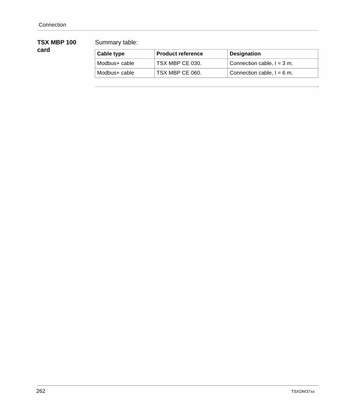
Connection
TSX MBP 100 card
Summary table:
Cable type Product reference Designation
Modbus+ cable TSX MBP CE 030. Connection cable, I = 3 m.
Modbus+ cable TSX MBP CE 060. Connection cable, I = 6 m.
262 TSX DM 37 xx
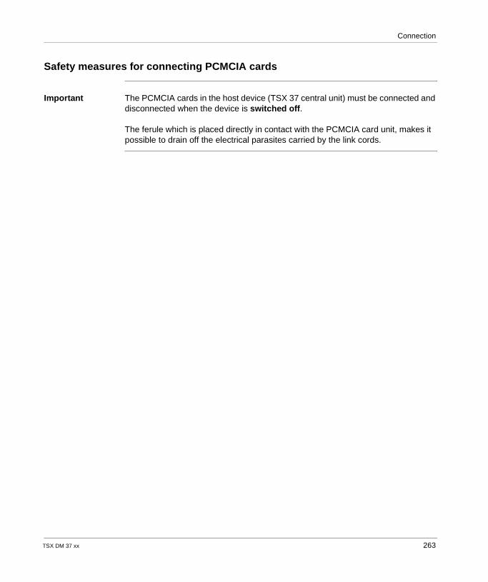
Connection
Safety measures for connecting PCMCIA cards
Important The PCMCIA cards in the host device (TSX 37 central unit) must be connected and disconnected when the device is switched off.
The ferule which is placed directly in contact with the PCMCIA card unit, makes it possible to drain off the electrical parasites carried by the link cords.
TSX DM 37 xx 263
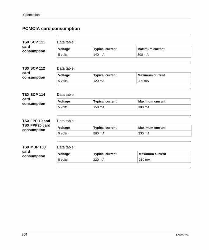
Connection
PCMCIA card consumption
TSX SCP 111 card consumption
Data table:
TSX SCP 112 card consumption
Data table:
TSX SCP 114 card consumption
Data table:
TSX FPP 10 and TSX FPP20 card consumption
Data table:
TSX MBP 100 card consumption
Data table:
Voltage Typical current Maximum current
5 volts 140 mA 300 mA
Voltage Typical current Maximum current
5 volts 120 mA 300 mA
Voltage Typical current Maximum current
5 volts 150 mA 300 mA
Voltage Typical current Maximum current
5 volts 280 mA 330 mA
Voltage Typical current Maximum current
5 volts 220 mA 310 mA
264 TSX DM 37 xx
TSX DM 37 xx
22
Communication via a Modem PCMCIA cardAt a Glance
Aim of this chapter
This chapter aims to describe communication via a Modem PCMCIA card.
What's in this Chapter?
This chapter contains the following topics:
Topic Page
At a Glance 266
Description 267
Installing the TSX MDM 10 card 268
Connecting to the telephone network 269
Connecting the adapters 271
Electrical features and technical specifications 272
265
Communication via a Modem PCMCIA card
At a Glance
General The TSX DMZ 10 card makes it possible to connect to the switched telephone network (STN) to access the remote stations following the UNI-TELWAY protocols or character mode.
This type of communication is available by using the Modem PCMCIA card as an intermediary. It can only be installed in the PCMCIA acceptance slot of a Micro PLC (TSX 37 21/22) Version V≥ 3.3.
266 TSX DM 37 xx
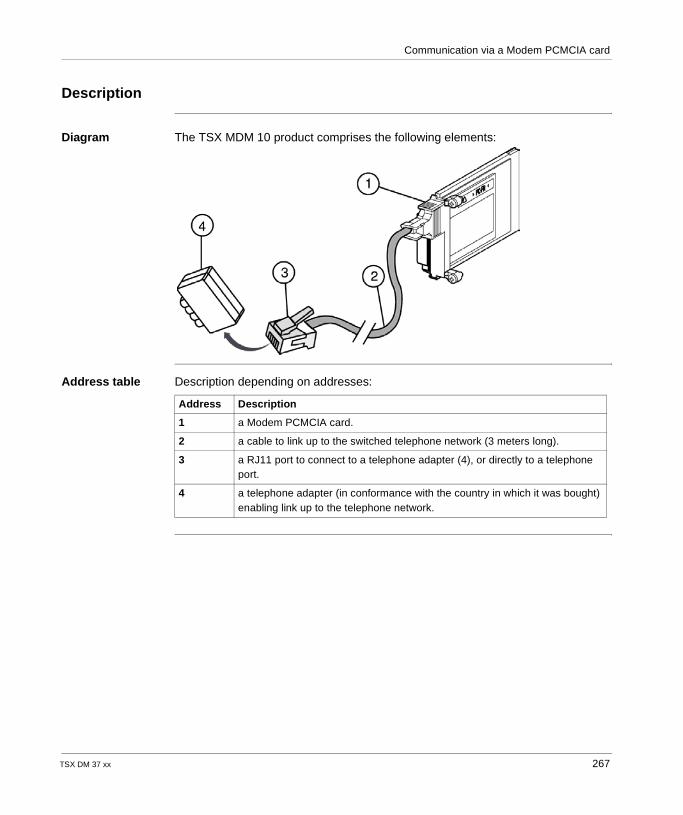
Communication via a Modem PCMCIA card
Description
Diagram The TSX MDM 10 product comprises the following elements:
Address table Description depending on addresses:
Address Description
1 a Modem PCMCIA card.
2 a cable to link up to the switched telephone network (3 meters long).
3 a RJ11 port to connect to a telephone adapter (4), or directly to a telephone port.
4 a telephone adapter (in conformance with the country in which it was bought) enabling link up to the telephone network.
TSX DM 37 xx 267
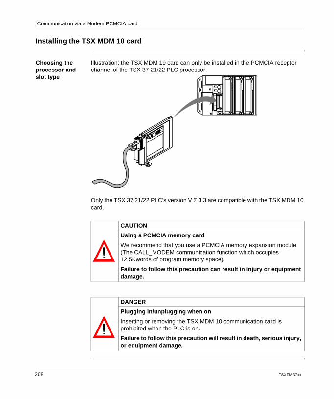
Communication via a Modem PCMCIA card
Installing the TSX MDM 10 card
Choosing the processor and slot type
Illustration: the TSX MDM 19 card can only be installed in the PCMCIA receptor channel of the TSX 37 21/22 PLC processor:
Only the TSX 37 21/22 PLC’s version V Σ 3.3 are compatible with the TSX MDM 10 card.
CAUTION
Using a PCMCIA memory card
We recommend that you use a PCMCIA memory expansion module (The CALL_MODEM communication function which occupies 12.5Kwords of program memory space).
Failure to follow this precaution can result in injury or equipment damage.
DANGER
Plugging in/unplugging when on
Inserting or removing the TSX MDM 10 communication card is prohibited when the PLC is on.
Failure to follow this precaution will result in death, serious injury, or equipment damage.
268 TSX DM 37 xx
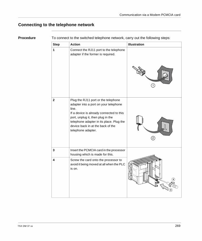
Communication via a Modem PCMCIA card
Connecting to the telephone network
Procedure To connect to the switched telephone network, carry out the following steps:
Step Action Illustration
1 Connect the RJ11 port to the telephone adapter if the former is required.
2 Plug the RJ11 port or the telephone adapter into a port on your telephone line.If a device is already connected to this port, unplug it, then plug in the telephone adapter in its place. Plug the device back in at the back of the telephone adapter.
3 Insert the PCMCIA card in the processor housing which is made for this.
4 Screw the card onto the processor to avoid it being moved at all when the PLC is on.
TSX DM 37 xx 269
Communication via a Modem PCMCIA card
DANGER
Inserting/removing the card
The host processor must be switched off when the card is inserted or removed.
Failure to follow this precaution will result in death, serious injury, or equipment damage.
270 TSX DM 37 xx
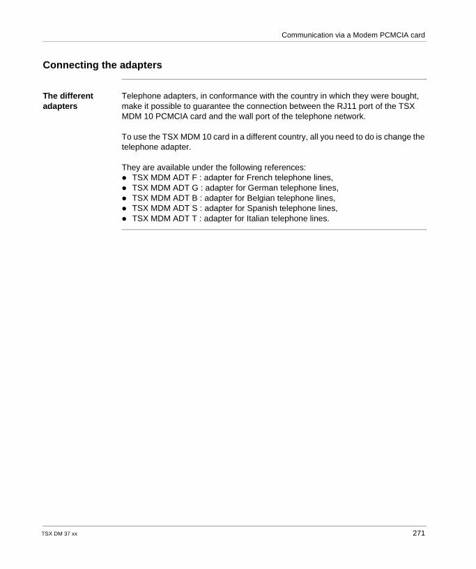
Communication via a Modem PCMCIA card
Connecting the adapters
The different adapters
Telephone adapters, in conformance with the country in which they were bought, make it possible to guarantee the connection between the RJ11 port of the TSX MDM 10 PCMCIA card and the wall port of the telephone network.
To use the TSX MDM 10 card in a different country, all you need to do is change the telephone adapter.
They are available under the following references: TSX MDM ADT F : adapter for French telephone lines, TSX MDM ADT G : adapter for German telephone lines, TSX MDM ADT B : adapter for Belgian telephone lines, TSX MDM ADT S : adapter for Spanish telephone lines, TSX MDM ADT T : adapter for Italian telephone lines.
TSX DM 37 xx 271
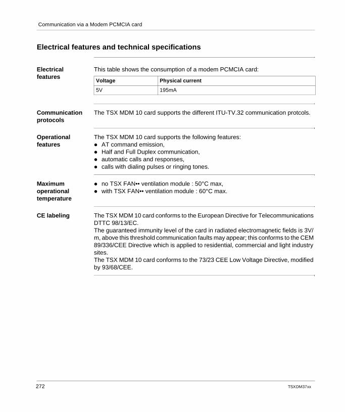
Communication via a Modem PCMCIA card
Electrical features and technical specifications
Electrical features
This table shows the consumption of a modem PCMCIA card:
Communication protocols
The TSX MDM 10 card supports the different ITU-TV.32 communication protcols.
Operational features
The TSX MDM 10 card supports the following features: AT command emission, Half and Full Duplex communication, automatic calls and responses, calls with dialing pulses or ringing tones.
Maximum operational temperature
no TSX FAN•• ventilation module : 50°C max, with TSX FAN•• ventilation module : 60°C max.
CE labeling The TSX MDM 10 card conforms to the European Directive for Telecommunications DTTC 98/13/EC.The guaranteed immunity level of the card in radiated electromagnetic fields is 3V/m, above this threshold communication faults may appear; this conforms to the CEM 89/336/CEE Directive which is applied to residential, commercial and light industry sites.The TSX MDM 10 card conforms to the 73/23 CEE Low Voltage Directive, modified by 93/68/CEE.
Voltage Physical current
5V 195mA
272 TSX DM 37 xx
CBAIndex
AABE-7CPA01 cabling, 139Analog module TSX AEZ 414, 40Analog module TSX ASZ 200, 66Analog module TSX ASZ 401, 60Analog modules, 16Analog modules catalog, 18Analog modules TSX AEZ 801/802, 28Association of the conductors
analog modules, 22Auxiliary input features, 116
CCabling for the analog module TSX AEZ 414, 52Cabling for the analog module TSX ASZ 200, 70Cabling for the analog module TSX ASZ 401, 64Cabling of modules TSX AEZ 801/802, 37capture inputs, 172Characteristics of analog modules TSX AEZ 801/802, 36characteristics of the TSX AMZ 600 module, 81
TSX DM 37 xx
Connectingan encoder TSX TAP S15 05, 155an encoder with a TSX TAP S15 24, 156TSX FPP 10, 256TSX FPP 20, 255TSX MBP 100, 257TSX MBP CE 030/060 Modicon 990 NAD 230 00 connection device side, 259
connectingencoders supplied with 10...30 V, 199encoders supplied with 5 V, 201TELEFAST 2
ABE-7CPA01, 182ABE-7CPA11, 197
Connecting the adapters, 271Connecting the EPSR input, 107Connecting the TSX SCP 112
to April 5000/7000 PLCs, 243Connecting the TSX SCP 114 card to the Modbus/Jbus, 251Connecting the TSX SCP 114 card to the UNI-TELWAY network, 249Connecting to the telephone network, 269Connection
counting sensors and their supply, 132DDP counting sensors, 130sensors on auxiliary inputs and their supply, 133supply and sensors on auxiliary inputs, 128to modules with HE10 connectors, 157
Connection of encoder type counting
273
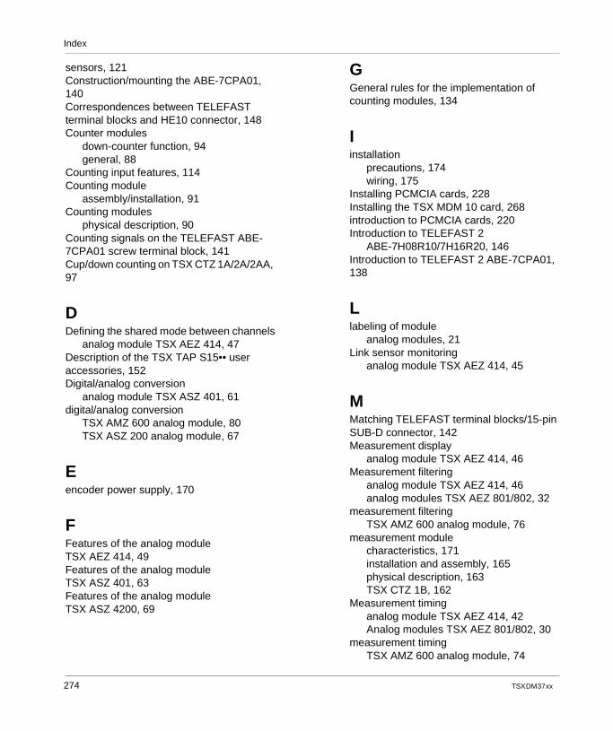
Index
sensors, 121Construction/mounting the ABE-7CPA01, 140Correspondences between TELEFAST terminal blocks and HE10 connector, 148Counter modules
down-counter function, 94general, 88
Counting input features, 114Counting module
assembly/installation, 91Counting modules
physical description, 90Counting signals on the TELEFAST ABE-7CPA01 screw terminal block, 141Cup/down counting on TSX CTZ 1A/2A/2AA, 97
DDefining the shared mode between channels
analog module TSX AEZ 414, 47Description of the TSX TAP S15•• user accessories, 152Digital/analog conversion
analog module TSX ASZ 401, 61digital/analog conversion
TSX AMZ 600 analog module, 80TSX ASZ 200 analog module, 67
Eencoder power supply, 170
FFeatures of the analog module TSX AEZ 414, 49Features of the analog module TSX ASZ 401, 63Features of the analog module TSX ASZ 4200, 69
274
GGeneral rules for the implementation of counting modules, 134
Iinstallation
precautions, 174wiring, 175
Installing PCMCIA cards, 228Installing the TSX MDM 10 card, 268introduction to PCMCIA cards, 220Introduction to TELEFAST 2
ABE-7H08R10/7H16R20, 146Introduction to TELEFAST 2 ABE-7CPA01, 138
Llabeling of module
analog modules, 21Link sensor monitoring
analog module TSX AEZ 414, 45
MMatching TELEFAST terminal blocks/15-pin SUB-D connector, 142Measurement display
analog module TSX AEZ 414, 46Measurement filtering
analog module TSX AEZ 414, 46analog modules TSX AEZ 801/802, 32
measurement filteringTSX AMZ 600 analog module, 76
measurement modulecharacteristics, 171installation and assembly, 165physical description, 163TSX CTZ 1B, 162
Measurement timinganalog module TSX AEZ 414, 42Analog modules TSX AEZ 801/802, 30
measurement timingTSX AMZ 600 analog module, 74
TSX DM 37 xx
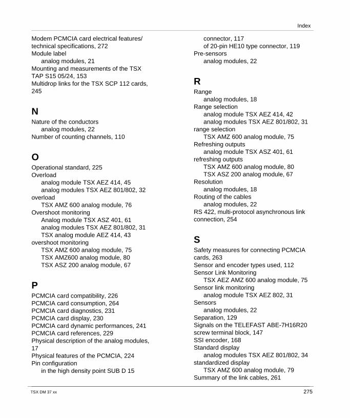
Index
Modem PCMCIA card electrical features/technical specifications, 272Module label
analog modules, 21Mounting and measurements of the TSX TAP S15 05/24, 153Multidrop links for the TSX SCP 112 cards, 245
NNature of the conductors
analog modules, 22Number of counting channels, 110
OOperational standard, 225Overload
analog module TSX AEZ 414, 45analog modules TSX AEZ 801/802, 32
overloadTSX AMZ 600 analog module, 76
Overshoot monitoringAnalog module TSX ASZ 401, 61analog modules TSX AEZ 801/802, 31TSX analog module AEZ 414, 43
overshoot monitoringTSX AMZ 600 analog module, 75TSX AMZ600 analog module, 80TSX ASZ 200 analog module, 67
PPCMCIA card compatibility, 226PCMCIA card consumption, 264PCMCIA card diagnostics, 231PCMCIA card display, 230PCMCIA card dynamic performances, 241PCMCIA card references, 229Physical description of the analog modules, 17Physical features of the PCMCIA, 224Pin configuration
in the high density point SUB D 15
TSX DM 37 xx
connector, 117of 20-pin HE10 type connector, 119
Pre-sensorsanalog modules, 22
RRange
analog modules, 18Range selection
analog module TSX AEZ 414, 42analog modules TSX AEZ 801/802, 31
range selectionTSX AMZ 600 analog module, 75
Refreshing outputsanalog module TSX ASZ 401, 61
refreshing outputsTSX AMZ 600 analog module, 80TSX ASZ 200 analog module, 67
Resolutionanalog modules, 18
Routing of the cablesanalog modules, 22
RS 422, multi-protocol asynchronous link connection, 254
SSafety measures for connecting PCMCIA cards, 263Sensor and encoder types used, 112Sensor Link Monitoring
TSX AEZ AMZ 600 analog module, 75Sensor link monitoring
analog module TSX AEZ 802, 31Sensors
analog modules, 22Separation, 129Signals on the TELEFAST ABE-7H16R20 screw terminal block, 147SSI encoder, 168Standard display
analog modules TSX AEZ 801/802, 34standardized display
TSX AMZ 600 analog module, 79Summary of the link cables, 261
275
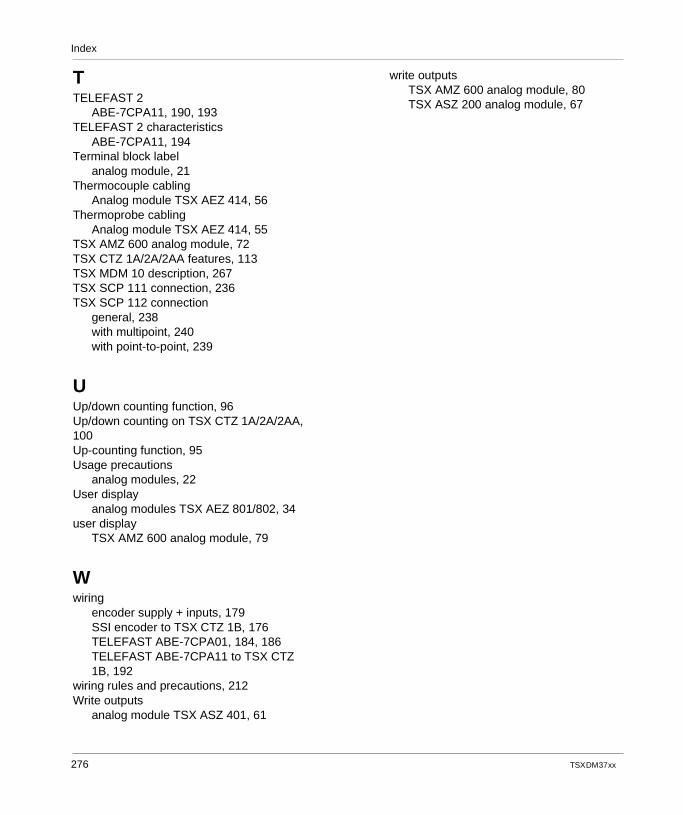
Index
TTELEFAST 2
ABE-7CPA11, 190, 193TELEFAST 2 characteristics
ABE-7CPA11, 194Terminal block label
analog module, 21Thermocouple cabling
Analog module TSX AEZ 414, 56Thermoprobe cabling
Analog module TSX AEZ 414, 55TSX AMZ 600 analog module, 72TSX CTZ 1A/2A/2AA features, 113TSX MDM 10 description, 267TSX SCP 111 connection, 236TSX SCP 112 connection
general, 238with multipoint, 240with point-to-point, 239
UUp/down counting function, 96Up/down counting on TSX CTZ 1A/2A/2AA, 100Up-counting function, 95Usage precautions
analog modules, 22User display
analog modules TSX AEZ 801/802, 34user display
TSX AMZ 600 analog module, 79
Wwiring
encoder supply + inputs, 179SSI encoder to TSX CTZ 1B, 176TELEFAST ABE-7CPA01, 184, 186TELEFAST ABE-7CPA11 to TSX CTZ 1B, 192
wiring rules and precautions, 212Write outputs
analog module TSX ASZ 401, 61
276
write outputsTSX AMZ 600 analog module, 80TSX ASZ 200 analog module, 67
TSX DM 37 xx


