Ernest T. SeligDepartment of Civil Engineering, (Emeritus),University of Massachusetts, and Ernest T. Selig, Inc.,Hadley, Massachusetts
24.1 INTRODUCTION
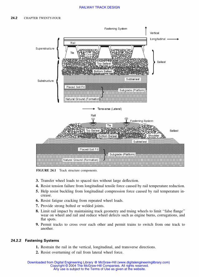
Railway track as it is considered in this chapter consists of a superstructure and a substruc-ture. The superstructure is composed of steel rails fastened to crossties. The rails are designedto support and guide flanged steel wheels through their prescribed position in space. Thesuperstructure is placed on a substructure. The substructure is composed of a layered systemof materials known as ballast, subballast and subgrade. These track components are illus-trated in Figure 24.1 (Selig and Waters 1994).
Special track components are added to perform needed functions. These include switchesto divert trains from one track to another, crossing diamonds to permit one track to crossanother, level grade crossings to permit roads to cross over the train track at the sameelevation, types of warning devices such as hot bearing detectors, and dragging equipmentdetectors. The last example is rail attached directly to a reinforced concrete slab in a tunnelor to a bridge structure. The substructure incorporates a drainage system to remove waterfrom the track.
The track design needs to consider soil and rock conditions, weather conditions (precip-itation, temperature), traffic requirements (wheel loads, total annual tonnage), and mainte-nance costs for the designed track.
This chapter will provide a listing of design functions, a description of design methods,and references to sources of information on design details.
24.2 FUNCTIONS OF TRACK COMPONENTS
For each of the main track components the functions are the following (Selig and Waters1994; Agarwal 1998; Hay 1982).
24.2.1 Rails
1. Guide the flanged wheels in the vertical, lateral, and longitudinal directions.2. Provide a smooth running surface.
Any use is subject to the Terms of Use as given at the website.
Source: HANDBOOK OF TRANSPORTATION ENGINEERING
24.2 CHAPTER TWENTY-FOUR
FIGURE 24.1 Track structure components.
3. Transfer wheel loads to spaced ties without large deflection.4. Resist tension failure from longitudinal tensile force caused by rail temperature reduction.5. Help resist buckling from longitudinal compression force caused by rail temperature in-
crease.6. Resist fatigue cracking from repeated wheel loads.7. Provide strong bolted or welded joints.8. Limit rail impact by maintaining track geometry and truing wheels to limit ‘‘false flange’’
wear on wheel and rail and reduce wheel defects such as engine burns, corrugations, andflat spots.
9. Permit tracks to cross over each other and permit trains to switch from one track toanother.
24.2.2 Fastening Systems
1. Restrain the rail in the vertical, longitudinal, and transverse directions.2. Resist overturning of rail from lateral wheel force.
Any use is subject to the Terms of Use as given at the website.
RAILWAY TRACK DESIGN
RAILWAY TRACK DESIGN 24.3
3. Connect sections of rail to permit safe and smooth train operation.4. Create a canted (inclined) surface to provide proper wheel / rail contact—wood ties.5. Spread the rail seat force over a larger part of the tie surface to reduce tie damage—
wood ties.6. Provide resiliency under the vertical wheel load—concrete ties.7. Reduce tie abrasion at rail seat—concrete ties.8. Provide damping of the high frequency wheel-induced vibrations—concrete ties.
24.2.3 Crossties
1. Transfer the vertical wheel load from the rail through the rail seat to the bottom of theties to provide an acceptable level or stress for the ties and ballast.
2. Hold the fastening system so that it can restrain the rails at the proper vertical, lateral,and longitudinal position and maintain the required gage.
3. Provide a canted (inclined) surface for proper wheel / rail contact—concrete ties.
24.2.4 Ballast
1. Restrain the ties against vertical, lateral, and longitudinal forces from the rails.2. Reduce the pressure from the tie-bearing area to a level that is acceptable for the under-
lying materials.3. Provide the ability to adjust track geometry by rearranging the ballast particles by tamping
and lining.4. Assist in drainage of water from the track.5. Provide sufficient voids between particles to allow an efficient migration of unwanted fine
particles from the ballast section.6. Provide some resiliency to the track to decrease rail, rail component, and wheel wear.
24.2.5 Subballast
1. Maintain separation between the ballast and subgrade particles.2. Prevent attrition of the hard subgrade surface by the ballast.3. Reduce pressure from the ballast to values that can be sustained by the subgrade without
adverse effects.4. Intercept water from the ballast and direct it to the track drainage system.5. Provide drainage of water flowing upward from the subgrade.6. Provide some insulation to the subgrade to prevent freezing.7. Provide some resiliency to the track.
24.2.6 Subgrade
1. Provide a stable platform on which to construct the track.2. Limit progressive settlement from repeated traffic loading.3. Limit consolidation settlement.
Any use is subject to the Terms of Use as given at the website.
RAILWAY TRACK DESIGN
24.4 CHAPTER TWENTY-FOUR
4. Prevent massive slope failure.5. Restrict swelling or shrinking from water content change.
24.2.7 Drainage
Drainage is the single most important factor governing the performance of track substructure.A properly functioning drainage system provides the following:
1. Intersects the water seeping up from the subgrade2. Diverts the surface water flowing toward the track3. Removes water falling onto the track4. Carry off stone dust, sand, and other debris that otherwise could foul the track.
24.3 TRACK FORCES
The forces applied to the track are vertical, lateral (parallel to the ties), and longitudinal(parallel to the rails). These forces are affected by train travel speed. An important point torecognize is that track design involves many force repetitions, not just one load, as in buildingfoundation design. Thus, allowable forces must be considerably smaller than the failureforces in a single load test in order to perform satisfactorily over a period of time. This haslong been recognized in the field of material fatigue.
24.3.1 Vertical
The main vertical force is the repetitive downward action of the wheel load. In addition, thiswheel / rail interaction produces a corresponding lift-up force on the ties away from the wheelload points.
The nominal vertical wheel force, also called the static force, is equal to the gross weightof the railway car divided by the number of wheels. This force ranges from about 12,000lb (53 kN) for light rail passenger cars to 39,000 lb (174 kN) for heavy freight cars. However,due to the inertial effects of the moving train traveling over varying geometry on a trackwith defects, the vertical load can be much greater or much smaller than the nominal value.The largest forces are produced from the impact of the wheel on the rail, which is accom-panied by vibration that often can be felt at considerable distance from the track. The passageof trains over the track causes the initial track geometry to deform. The inertia of the movingtrain causes the vertical wheel force to vary above and below the nominal wheel load. Thevertical impact dynamic load has two components, a short-duration larger force and a longer-duration smaller force. The first is expected to be more harmful to the rails and ties, whilethe second does more damage to the ballast and track geometry.
The major factors affecting the magnitude of the dynamic vertical forces are:
Any use is subject to the Terms of Use as given at the website.
RAILWAY TRACK DESIGN
RAILWAY TRACK DESIGN 24.5
• Track geometry
• Track modulus or vertical track stiffness
The traditional approach for representing the geometry-driven dynamic wheel load is tomultiply the nominal wheel load by an impact factor that is greater than 1.
The impact factor recommended by AREMA (2003, chap. 16) is a function of the traintravel speed and the wheel diameter. The actual maximum dynamic force on any track maybe much different from that obtained from this approach.
These dynamic wheel forces increase the rate of track component deterioration. For ex-ample, studies in Europe (Esveld 1989) have indicated that the maintenance cost ratio isrepresented by the force ratio to the power n. Values of n from European work are 1 for railfatigue, 3 for track geometry deterioration, and 3.5 for rail surface defects.
24.3.2 Lateral
One type of lateral force applied to the rail is the wheel force transmitted through frictionbetween the wheel and top of the rail and by the wheel flange acting against the inside faceof the rail head, particularly on curves. Another lateral force is the rail buckling resistanceforce.
The design lateral wheel force depends upon a number of factors, including:
• Vehicle speed
• Track geometry
• Elevation difference between the two rails at the same cross section
• Transverse hunting movement due to the train-track dynamics
As the train speed increases, the lateral force outward on the outside rail of curves in-creases, and simultaneously the lateral force on the inside rail decreases.
When the field joints in the track are removed and the rails are welded, long lengths oftrack result, which are subjected to considerable changes in longitudinal stress due to railtemperature changes. Temperature decrease relative to the temperature at the time of weldingcauses tensile force parallel to the rail, which can result in rail pull-apart, while temperatureincrease causes compressive force, which can result in track buckling.
The wheels on a railway vehicle are tapered so that the diameter decreases from the insideto the outside. This helps center the wheels on straight track and compensates in part forthe greater distance that the outer wheels travel on a curve. Because the wheels are fixed tothe axle, both wheels must turn together. Thus, wheel slip is required to the extent that thecircumference of the wheels does not compensate for the difference in the inside and outsiderail length in a curve. The vehicle wheels on a fixed axle may take a longer time than thecurve spiral allows to become oriented to the curvature of the rail. This causes additionalstress on the gage or wheel climb on the high rail, and rollover possibilities on the lowrail.
A flange on the inside face of each wheel limits the lateral movement of the wheels tothe distance between the wheel flange and the inside face (gage) of the rail. The combinationof the wheel and railhead shapes, the inclination of the rails (cant), and the difference inelevation between the inside and outside rail in a curve serve to guide the train wheels alongthe intended alignment.
A spiral is a transition between the tangent track (straight) and the full radius curve. Ina curve the outer rail is at a higher elevation than the inner rail so that the resultant of theweight of the train, the load balance in the car, and the centrifugal force is designed to beperpendicular to the track. This is a function of train speed, so if the train is operating above
Any use is subject to the Terms of Use as given at the website.
RAILWAY TRACK DESIGN
24.6 CHAPTER TWENTY-FOUR
the design speed there will be a transverse force causing the flanges of the wheel to moveagainst the outer rail. In cases of lower than design speed, the transverse force will moveagainst the inner rail.
To achieve the desired alignment, the geometric components of a track are tangents,spirals (transition between straight track and constant radius curves), and constant radiuscurves in the horizontal plane, and gradients and vertical curves in the vertical plane.
24.3.3 Longitudinal
Sources of longitudinal rail forces are:
• Speed
• Locomotive traction
• Locomotive and car braking
• Expansion and contraction of the rails from temperature change
• Track grade
• Special track, i.e., turnouts, at grade crossings, rail crossings, dragging equipment, hotbearing detectors
The ratio of lateral to vertical force (L /V) is also important because it can cause loss ofalignment and even track buckling.
24.4 TRACK SYSTEM CHARACTERISTICS
Track system performance is a function of the composite response of the track componentsunder the action of the train loads. Two response characteristics are important to consider intrack design: vertical track stiffness and lateral track stability.
24.4.1 Stiffness
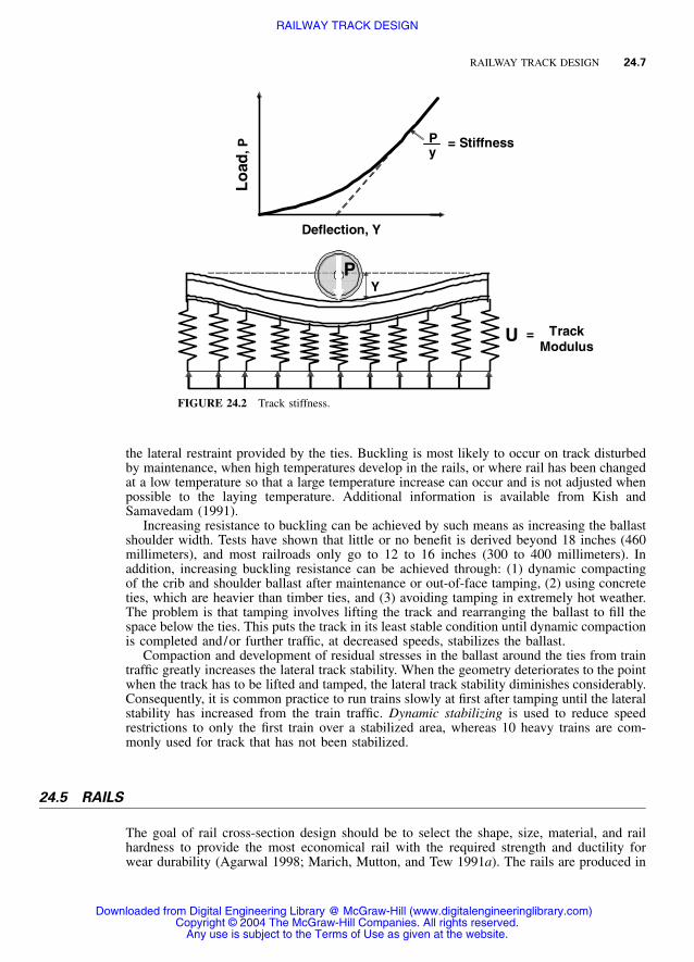
The vertical response model is illustrated in Figure 24.2. The vertical track stiffness k is thevertical load on one rail divided by the vertical deflection at the loaded point. The trackmodulus u is the composite vertical support stiffness of the rails consisting of the fasteners,ties, ballast, subballast, and subgrade. Track modulus cannot be measured directly, but iscalculated from track stiffness using the bending stiffness of the rail (Selig and Waters 1994).
Comparable models for horizontal (longitudinal and lateral) track response are not avail-able.
The subgrade is the component that has the greatest influence on the track stiffness. It isalso the component with the most variation and the most uncertainty about its propertyvalues. The track should be designed to have a stiffness that is neither too high nor too low.Both extremes will shorten the life of the components.
24.4.2 Lateral Stability
Track buckling is a result of increasing longitudinal rail force from increasing temperature.Buckling occurs in the lateral direction. Because this is the least stable direction, the lateralresistance is greatest directly under the wheel loads because the weight of the train increases
Any use is subject to the Terms of Use as given at the website.
RAILWAY TRACK DESIGN
RAILWAY TRACK DESIGN 24.7
YP
U = TrackModulus
Deflection, YL
oad
, P
Py
= Stiffness
FIGURE 24.2 Track stiffness.
the lateral restraint provided by the ties. Buckling is most likely to occur on track disturbedby maintenance, when high temperatures develop in the rails, or where rail has been changedat a low temperature so that a large temperature increase can occur and is not adjusted whenpossible to the laying temperature. Additional information is available from Kish andSamavedam (1991).
Increasing resistance to buckling can be achieved by such means as increasing the ballastshoulder width. Tests have shown that little or no benefit is derived beyond 18 inches (460millimeters), and most railroads only go to 12 to 16 inches (300 to 400 millimeters). Inaddition, increasing buckling resistance can be achieved through: (1) dynamic compactingof the crib and shoulder ballast after maintenance or out-of-face tamping, (2) using concreteties, which are heavier than timber ties, and (3) avoiding tamping in extremely hot weather.The problem is that tamping involves lifting the track and rearranging the ballast to fill thespace below the ties. This puts the track in its least stable condition until dynamic compactionis completed and/or further traffic, at decreased speeds, stabilizes the ballast.
Compaction and development of residual stresses in the ballast around the ties from traintraffic greatly increases the lateral track stability. When the geometry deteriorates to the pointwhen the track has to be lifted and tamped, the lateral track stability diminishes considerably.Consequently, it is common practice to run trains slowly at first after tamping until the lateralstability has increased from the train traffic. Dynamic stabilizing is used to reduce speedrestrictions to only the first train over a stabilized area, whereas 10 heavy trains are com-monly used for track that has not been stabilized.
24.5 RAILS
The goal of rail cross-section design should be to select the shape, size, material, and railhardness to provide the most economical rail with the required strength and ductility forwear durability (Agarwal 1998; Marich, Mutton, and Tew 1991a). The rails are produced in
the factory by hot-rolling the steel, and then cooled and straightened to form finished lengthsof 80 feet (24 meters). Fixed welding plants, where the customer can send rail to be welded,are located all over North America. Mobile welding plants will come to a railroad, and in-track-flash butt welding machines will go on their track and weld jointed rails together. Mostrailroads still use thermite welds for rail change-outs and other short jobs in the field. Theselengths can be electric flash-butt-welded (EFW) to form longer lengths, typically 1,440 feet(439 meters), that can be transported to the field for installation.
The rail may be heat-treated at the mill for increased hardness to increase the wearingresistance. Varying the steel composition can also give increased hardness with a slight lossof ductility. Overall rail life increases as the rail weight increases largely due to the abilityto maintain profile over the thicker head with increased maintenance grinding. Rail propertiesto consider when choosing the size and type of rail are:
1. Wearability2. Hardness3. Ductility4. Manufacture defects in the rail material5. Rail straightness
The rail sections are connected in the field by either bolted joints or welding. The loca-tions of the bolted joints are high-maintenance areas because of the impact of the wheelspassing the rail end gap at the center of the joints. The combination of the impact load andreduced rail stiffness of the supporting joint bars causes greater stress on the fasteners, ties,ballast, and subgrade. This in turn causes fastener looseness, plate cutting (wood ties), paddeterioration and concrete tie seat abrasion (concrete ties) and more rapid track settlementand geometry deterioration. This problem can be reduced by eliminating the joints by fieldwelding. This approach is preferred on high-speed and heavy axle load (HAL) lines.
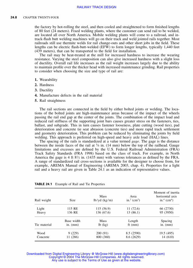
The spacing of the rails is standardized at a value termed gage. The gage is the distancebetween the inside faces of the rail at 5⁄8 in. (14 mm) below the top of the railhead. Gaugelimitations and excesses are defined by the U.S. Federal Railroad Administration (FRA)Track Safety Standards (FRA 1998) based on the class of track. For example, in NorthAmerica the gage is 4 ft 81⁄2 in. (1435 mm) with various tolerances as defined by the FRA.A range of standardized rail cross-sections is available for the designer to choose from, forexample, AREMA Manual of Engineering (AREMA 2003, chap. 4). Properties for a lightrail and a heavy rail are given in Table 24.1 as an indication of representative values.
Any use is subject to the Terms of Use as given at the website.
RAILWAY TRACK DESIGN
RAILWAY TRACK DESIGN 24.9
24.6 TIES
Concrete ties are both prestressed and reinforced. AREMA (2003, chap. 10) recommendsthat the average ballast pressure at the base of concrete ties not exceed 85 psi (590 kPa) forhigh-quality abrasion-resistant ballast. AREMA (2003, chap. 16) recommends a limit of 65psi (450 kPa). The pressure would be reduced for lower quality ballast. The limits shouldalso consider the durability of the tie bottoms, but this is not a part of the AREMA consid-eration for the maximum pressure. The reason it should be considered is because the abrasionresistance of the cement in concrete is less than the resistance of much of the rock currentlyused for ballast.
Timber ties are both hardwood and softwood. Natural wood used for timber ties will havedefects such as knots, splits, checks, and shakes. Specifications exist (for example, seeAREMA (2003, chap. 3)) for the maximum size of allowed defects. Wood ties are treatedwith a preservative for protection against deterioration from bacteria, insects, and fire. Theperformance of the track can help project the need for maintenance. The upper curve rep-resents a low-quality track because of the rapid increase in roughness with time.
Timber is the most common material used for the manufacture of crossties in NorthAmerica. Next most common is prestressed/reinforced concrete. A small percentage of cross-ties are manufactured from other materials such as steel and cast iron. Some new materialsare being introduced such as glued wood laminates and recycled plastic. Representativevalues of concrete and timber tie properties are given in Table 24.1. Concrete ties, at ap-proximately 800 pounds (360 kilograms), are heavier than timber ties, at approximately 200pounds (91 kilograms), so concrete resists track buckling better but timber ties are easier tohandle. Concrete ties generally have more secure fastening systems than timber, so concreteholds the rails better. Timber ties have natural resiliency, whereas concrete ties require com-pressible pads for some resiliency.
One design consideration is the bending stresses in the ties caused by the wheel loadsmoving over the tie. These bending stresses are significantly affected by the pressure distri-bution of the ballast along the bottom of the ties. When the track is lifted and tamped tosmooth the geometry, a gap is produced under the middle of the ties to cause the tie-bearingarea to be limited to the tamp zone on both sides of the rail. With traffic the track will settle,eventually bringing the center of the tie into contact with the ballast. This condition, calledcenter binding, will greatly increase the bending stresses in the ties. Because it is not possibleto predict the exact pressure distribution along the bottom of the tie, some simplified as-sumptions are commonly used (Marich, Mutton, and Tew 1991b).
Analysis of the pressure distribution using the vertical track model shows that the distri-bution is dependent upon the flexibility of the tie, the contact-bearing area between the ballastand the tie, the compactness of the ballast under the tie, and stiffness of the subballast,ballast, and subgrade. The peak values of pressure distribution are also a function of the tiebase dimensions and the center-to-center tie spacing.
The vertical track model, if available, can determine the maximum rail seat loads. Therail seat loads can also be estimated using the beam on elastic foundation model, whichrequires an estimate of the track modulus and the bending characteristics of the rail (Seligand Waters 1994; Hay 1982).
The maximum tie-bending moments depend on all the same factors as the maximumcontact pressure at the base of the tie. The maximum bending moments are at the rail seatand the center of the tie length. Because of the difficulty of accurately predicting the max-imum bending moments and bending stresses as well as contact pressures, it is quite commonto select the ties based on experience in track, in the environment, and under the loadingfor the design conditions. In this regard, both the maximum magnitude and the number ofrepetitions must characterize the load. The latter affects the durability requirement (e.g.,ballast crushing, tie abrasion, and fatigue life).
Any use is subject to the Terms of Use as given at the website.
RAILWAY TRACK DESIGN
24.10 CHAPTER TWENTY-FOUR
To complete the design based on flexural considerations, the maximum allowable bendingstress needs to be determined. This can be calculated from the maximum bending moment.The maximum bending stress depends upon the material from which the tie is constructed.The use of tie plates between the rails and the ties will spread the rail seat load and thereforefurther reduce the bending moment.
AREMA (2003, chap. 3) indicates that an estimate of the maximum allowable bendingstress in the timber ties under repeated wheel loading could be taken as 28 percent of themodulus of rupture in bending test to failure. Accordingly, values were reported as 1 ksi (7MPa) for softwood and 1.3 ksi (9 MPa) for hardwood. Similar methods have been developedfor reinforced concrete and steel ties. The designer must ensure that the appropriate valuesof the maximum bending stress under repeated loading are obtained for the ties being con-sidered.
A less conservative assumption that the ballast bearing pressure under concrete ties isuniformly distributed may be appropriate for these materials because their properties arebetter controlled and the ties are more expensive.
24.7 FASTENING SYSTEMS
A rail joint is desired to be as stiff and strong as the rail itself. Welded joints approach thiscondition, but bolted joints do not (Talbot 1933). The bolted joints have bars that fit withinthe railhead and base fillets and against the web of the rail. Holes are drilled through therail concentric with the holes in the joint bars. Insulation can be placed between the barsand the rail to electrically isolate the signal circuits.
For timber ties, steel tie plates are fit to the rail base with a 1⁄4-inch (6.4-millimeter)shoulder on either side of the base for line-spiking and up to 18 inches (460 millimeters) inlength secured to the timber tie with 6-inch (150-millimeter) cut spikes or screw spikes. Theplates are placed between the rail and the tie surface to spread the rail seat load. The plateswork together with a variety of rail anchors or other elastic fasteners for horizontal andlateral restraint of the track. The tie plates provide the cant to the rail. Tie plates are availablein a variety of sizes (AREMA 2003, chap. 5).
Tie plates come with four holes. Cut spikes are used in a variety of patterns dependingon the geometry of the track, tangent, or curve. At least one spike is driven through the holeimmediately outside the shoulder on each side of the rail for line stability. Again, at leastone spike is driven through the opposing corner at each end of the plate to hold the platein position on the tie. The primary function of the spike is to hold the plate to the tie andprovide line stability for the rail as it fits within the shoulders of the tie plate. The heads ofthe spikes are driven down to a 1⁄8-inch (3-millimeter) height above the top of the rail base,but through time and the natural plate cut that occurs from the flexing and uplift of the rail,spikes are lifted up somewhat while still providing stable line. Specifications and properspike driving patterns are given in AREMA (2003, chap. 5).
For concrete ties, spring clips, known as elastic fasteners, are connected to the top of tieand press down on the top of the rail base and against the web of the rail. These samefasteners come secured within the concrete tie pour, which makes fewer parts and morestable holding ability. There are several other elastic fastener designs on the market, all ofwhich are designed to secure the rail in vertical, lateral, and longitudinal directions. A padis placed between the bottom of the tie and the rail seat to provide resiliency and insulationfor signal conductivity and help prevent rail seat and tie abrasion due to the L /V forcesresulting from the load.
Any use is subject to the Terms of Use as given at the website.
RAILWAY TRACK DESIGN
RAILWAY TRACK DESIGN 24.11
24.8 BALLAST
The ballast component of track shown in Figure 24.1 is subdivided into four zones:
1. Crib—material between the ties2. Shoulder—material beyond the tie ends down to the bottom of the ballast layer3. Top ballast—upper portion of supporting ballast layer that is disturbed by tamping4. Bottom ballast—lower portion of supporting ballast layer, which is not disturbed by tamp-
ing and generally is the more fouled
The mechanical properties of the ballast layer result from a combination of the physicalproperties of the individual particles and the degree of fouling together with the in-placedensity of the assembly of particles. Fouling refers to the small particles that infiltrate thespace between the ballast particles. The main factors producing the density are tamping, andtrain traffic. Tamping involves the insertion of tools into the ballast to rearrange the particlesto fill the space under the ties resulting from track lift. This leaves the ballast in a relativelyloose state. The many load cycles from the trains produce most of the compaction. Most ofthe major freight and passenger railroads use a combination of measured dynamic stabilizingand restricted speed over disturbed track.
24.8.1 Ballast Particle Requirements
Index tests have been established for characterizing the ballast properties. These cover me-chanical strength, shape, water absorption, specific gravity, surface texture, particle size, andbreakdown from cycles of freezing and thawing. Each railroad has a set of ballast specifi-cations that stipulates limits for the values from the index tests. These specifications areknown to be insufficient for ensuring satisfactory performance. One major limitation is thatno correlation exists between index tests so that trade-offs can be established between twoballast materials, which differ in the values of the individual index properties. Petrographicanalysis of the parent rock is a valuable aid in assessing ballast suitability. This informationshould be supplemented by observations of performance in track.
For ballast to perform its intended functions (section 24.2.4), it should consist of thefollowing characteristics:
1. Most particles in the 0.8- to 2.5-inch (19- to 64-millimeter) size range2. Produced by crushing hard, durable rock3. Planar fractured faces intersecting at sharp corners (to give angularity)4. Particles with a maximum ratio of 3:1 for largest to smallest dimensions5. Rough surface texture preferred6. Low water absorption
The relatively small range of particle size limits segregation when the particles are rear-ranged during tamping and also minimizes the loosening effect of the tamping process. Thelarge size of particles creates large void spaces to permit migration and holding of fineparticles while delaying the time when the ballast performance is significantly degraded byaccumulation of the fine particles. The condition also permits rapid flow of water throughthe ballast layer. The fractured faces, with rough texture and high angularity together withrestrictions on the amount of flat and elongated particles, provide high strength and stabilityfor the assembly of ballast particles. Hard, durable rock is needed to reduce the particle
Any use is subject to the Terms of Use as given at the website.
RAILWAY TRACK DESIGN
24.12 CHAPTER TWENTY-FOUR
breakage caused by the repeated train loading and from the tamping action during mainte-nance to smooth the track geometry. The low water absorption indicates stronger particlesand reduces breakdown from water expansion during freezing temperatures. The stress-reduction function depends of the above characteristics and the layer thickness.
The optimum choice of particle characteristics depends on the magnitude of axle loadand number of repetitions, together with the cost to deliver the ballast. Lower-quality ballastcan be more cost-effective than higher-quality ballast on low-traffic lines, especially whenthe lower-quality ballast is closer.
24.8.2 Ballast Fouling
Over a period of time in track the ballast gradation typically becomes broader and finer thanthe initial condition because the larger ballast particles will break into smaller particles andadditional smaller particles from a variety of sources will infiltrate the voids between theballast particles. This process is known as fouling. Five categories of fouling material havebeen identified:
1. Particles entering from the surface such as wind-blown sand or coal fines falling out ofcars
2. Products of wood or concrete tie wear3. Breakage and abrasion of the ballast particles by train loading4. Particles migrating upward from the granular layer underlying the ballast5. Migration of particles from the subgrade
The main causes of ballast fouling should be identified so that proper steps can be takento reduce the rate of fouling. The most frequent cause of ballast fouling is ballast breakdown,but there are individual situations in which each one of the other categories dominates.Geotextiles (filter fabrics) generally have not been found to be useful in solving ballastfouling problems (Selig and Waters 1994). A proper subballast layer is the best cure forfouling from the underlying granular layer and from the subgrade. When subgrade is thesource of fouling material one of two main mechanisms usually is present: (1) abrasion ofthe subgrade surface by ballast particles in contact with the subgrade, or (2) crack pumpingresulting from hydraulic erosion of water-filled cracks in the subgrade subjected to repeatedtrain loading.
Most commonly observed fouling problems are restrictions of drainage and interferencewith track maintenance. However, as the voids become completely filled with fines, theballast begins to take on the characteristics of the fines, with the ballast particles acting asfiller. Soaked fines represent mud and hence the ballast becomes soft and deformable. Whenwet fouled ballast becomes frozen the resiliency is lost. When the fines become dried (butstill moist), they act as a stiff binding agent for the crushed rock particles. This also causesloss of resiliency. All of these conditions prevent proper track surfacing.
The term cemented ballast is frequently used in the railroad industry to represent a con-dition in which the ballast particles are bound together. Although this term has not beenofficially defined, in most cases it appears to be used to represent dried fouled ballast.However the word cemented has led to the notion that a chemical bonding is involved, suchas in the case of portland cement, a derivative of limestone rock. This is one of the reasonsgiven by the railroad industry for preferring not to use limestone ballast.
A thorough examination of cemented ballast conditions is needed to determine the cause.Such a study could very well show that chemical bonding as in cement is not the mainbonding mechanism in cemented ballast because it is not normally the type of bonding indried fouled ballast.
Any use is subject to the Terms of Use as given at the website.
RAILWAY TRACK DESIGN
RAILWAY TRACK DESIGN 24.13
24.8.3 Petrographic Analysis
The value of petrographic analysis as a means of assessing and/or predicting behavior of anaggregate has been long recognized by the concrete industry. Techniques for evaluatingaggregate for use in concrete and for examining hardened concrete have been established byASTM in standards C295 for aggregate and C856 for hardened concrete. The purposes ofthis petrographic examination are
1. To determine the physical and chemical properties of the material that will have a bearingon the quality of the material for the intended purpose
2. To describe and classify the constituents of the sample3. To determine the relative amounts of the constituents of the sample, which is essential
for the proper evaluation of the sample, especially where the properties of the constituentsvary significantly
The value of the petrographic analysis depends to a large extent on the ability of the pe-trographer to correlate data provided on the source and proposed use of the material withthe findings of the petrographic examination.
Petrographic analysis is very helpful in the selection of a suitable quarry for ballast andalso for prediction of the shape and character of the components of future ballast breakdown(i.e., the fines generated by breakage and abrasion of the ballast). An experienced petrog-rapher can estimate the relative mechanical properties, including hardness, shape, type offracture, and durability in track.
24.8.4 Ballast Compaction
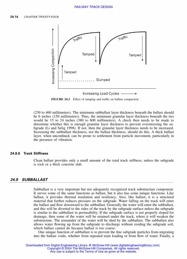
At the time when surfacing is required to correct track geometry irregularities, the ballast isin a dense state, particularly beneath the tie-bearing areas. When the rail and tie are raisedto the desired elevation, tamping tines are inserted in the crib next to the rail to displace theballast into the voids under the tie that were created by the raise. This tamping processdisturbs the compact state of the ballast and leaves it loosened (Figure 24.3). The morefouled the ballast is, and the greater the raise, the looser the ballast is after tamping.
The loosened ballast beneath the tie results in renewed settlement as the traffic, or trackequipment made for this purpose, stabilizes the ballast. The loosened crib ballast results ina significant reduction in lateral buckling resistance of the rail in the unloaded state. Cribsurface vibratory compactors can be used to compact the crib ballast immediately aftertamping, but not the ballast under the tie.
Traffic is the most effective means of compacting ballast under the tie, but this takes timeand results in nonuniform track settlement. Traffic also causes crib ballast to stabilize.
In addition to increasing density, there is evidence that both the traffic and the cribcompactor produce residual horizontal stresses in the ballast. These residual stresses may beone of the most important factors influencing ballast performance in track. Fouled ballast inthe crib will reduce densification of crib ballast by traffic after tamping and hence diminishany tendency for the development of lateral residual stress against the sides of the ties.
At present no adequate correlation exists between ballast index tests as a group and ballastperformance in track. What is needed to select ballast is a method that takes into accountthe effect of differences in ballast gradation and particle composition and, in addition, sim-ulates field service conditions such as ballast depth, subgrade characteristics, traffic loading,and track parameters.
24.8.5 Ballast Layer Thickness
The thickness of the ballast layer beneath the ties should generally be the minimum that isrequired for the ballast to perform its intended functions. Typically this will be 9 to 18 inches
Any use is subject to the Terms of Use as given at the website.
RAILWAY TRACK DESIGN
24.14 CHAPTER TWENTY-FOUR
FIGURE 24.3 Effect of tamping and traffic on ballast compaction.
(230 to 460 millimeters). The minimum subballast layer thickness beneath the ballast shouldbe 6 inches (150 millimeters). Thus, the minimum granular layer thickness beneath the tieswould be 15 to 24 inches (380 to 600 millimeters). A check then needs to be made todetermine whether this is enough granular layer thickness to prevent overstressing the su-bgrade (Li and Selig 1998). If not, then the granular layer thickness needs to be increased.Increasing the subballast thickness, not the ballast thickness, should do this. A thick ballastlayer, when unconfined, can be prone to settlement from particle movement, particularly inthe presence of vibration.
24.8.6 Track Stiffness
Clean ballast provides only a small amount of the total track stiffness, unless the subgradeis rock or a thick concrete slab.
24.9 SUBBALLAST
Subballast is a very important but not adequately recognized track substructure component.It serves some of the same functions as ballast, but it also has some unique functions. Likeballast, it provides thermal insulation and resiliency. Also, like ballast, it is a structuralmaterial that further reduces pressure on the subgrade. Water falling on the track will enterthe ballast and flow downward to the subballast. Generally the water will enter the subballast,and this will be diverted to the sides of the track by the subgrade surface unless the subgradeis similar to the subballast in permeability. If the subgrade surface is not properly sloped fordrainage, then some of the water will be retained under the track, where it will weaken thesubstructure. The remainder of the water will be shed by the subballast. The subballast alsoallows water flowing up from the subgrade to discharge without eroding the subgrade soil,which ballast cannot do because ballast is too coarse.
One unique function of subballast is to prevent the fine subgrade particles from migratinginto the ballast voids, whether from repeated train loading or from flow of water. Finally, a
particularly important function of subballast is to prevent the ballast particles from cominginto contact with the subgrade soil, where they abrade or grind away the subgrade surface(subgrade attrition). The fine soil particles produced then mix with water and form mud thatsqueezes into the ballast voids. This is mainly a problem with hard subgrade. Inserting a 6-inch (150-millimeter) layer of properly graded and durable subballast between the ballastand the subgrade solves the problem.
Crushing durable rock to form sand- and gravel-sized particles forms subballast. Suitablesubballast materials are commonly found in natural deposits. The aggregate must be resistantto breakdown from cycles of freezing and from repeated cycles of train loading. However,the durability requirements are not as severe as for ballast because the subballast particlesare smaller and the stresses are lower. The finest particles less than 0.003 inch (0.075 mil-limeter) must be nonplastic. Depending on the permeability requirements for drainage, thefine particles must not exceed 5 to 10 percent by weight and may be less than 0 to 2 percentin some cases. Subballast materials satisfying these requirements, when placed and com-pacted, will satisfy the structural requirements of pressure reduction to the subgrade andresiliency.
Subballast must be well drained so that it is not saturated during repeated train loading,particularly dynamic loading from impact forces. Saturated and undrained subballast mate-rials can deform significantly during train loading and even liquefy.
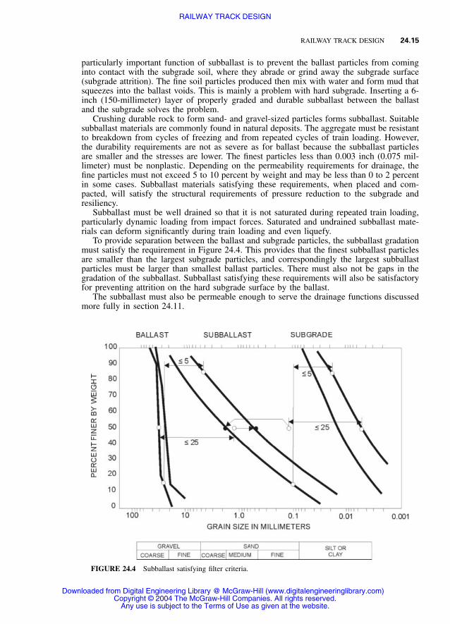
To provide separation between the ballast and subgrade particles, the subballast gradationmust satisfy the requirement in Figure 24.4. This provides that the finest subballast particlesare smaller than the largest subgrade particles, and correspondingly the largest subballastparticles must be larger than smallest ballast particles. There must also not be gaps in thegradation of the subballast. Subballast satisfying these requirements will also be satisfactoryfor preventing attrition on the hard subgrade surface by the ballast.
The subballast must also be permeable enough to serve the drainage functions discussedmore fully in section 24.11.
Any use is subject to the Terms of Use as given at the website.
RAILWAY TRACK DESIGN
24.16 CHAPTER TWENTY-FOUR
To provide freezing protection of the subgrade and not contribute to frost heave-thawsoftening problems, the subballast must be well drained and contain less than 5 percent fines(silt and clay-sized particles).
24.10 SUBGRADE
The subgrade is the platform upon which the track structure is constructed. Its main functionis to provide a stable foundation for the subballast and ballast layers. The influence of thetraffic-induced stresses extends downward as much as 5 meters below the bottom of the ties.This is considerably beyond the depth of the ballast and subballast. Hence, the subgrade isa very important substructure component that has a significant influence on track performanceand maintenance. For example, subgrade is a major component of the superstructure supportresiliency and hence contributes substantially to the elastic deflection of the rail under wheelloading. In addition, the subgrade stiffness magnitude is believed to influence ballast, rail,and sleeper deterioration. Subgrade also is a source of rail differential settlement due tomovement of the subgrade from various causes.
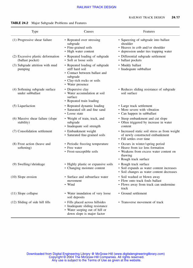
The various types of subgrade problems are listed in Table 24.2 together with their causesand features.
The subgrade may be divided into two categories (Figure 24.1): (1) natural ground (for-mation) and (2) placed soil (fill). Anything other than soils existing locally are generallyuneconomical to use for the subgrade. Existing ground should be used without disturbanceas much as possible. However, techniques are available to improve soil formations in placeif they are inadequate. Often some of the formation must be removed to construct the trackat its required elevation, which is below the existing ground surface. This puts the track ina cut with the ground surface sloping downward toward the track. If the excavation interceptsthe water table, slope erosion or failure can occur, carrying soil onto the track. Placed fill isused either to replace the upper portion of unsuitable existing ground or to raise the subgradesurface to the required elevation for the superstructure and the remainder of the substructure.
The subgrade is often the weakest substructure layer. Thus, a combined ballast and sub-ballast thickness is required that will reduce the pressure on the subgrade to a level thatproduces an acceptably small deformation from the repeated train loading for the desireddesign life. The design method must consider the type and strength of the subgrade soil, thedistribution of dynamic wheel loads and number of repetitions, and the substructure layerresilient moduli. The various levels of wheel loads and their corresponding numbers of cyclesare converted to a single representative design load and equivalent number of cycles.
The design method is described in detail in Li and Selig (1998). Two analyses are per-formed:
• Limiting the cumulative plastic strain on the subgrade surface accompanying progressiveshear to an acceptably small value over the life of the track to restrict the subgrade squeeze
• Limiting the cumulative plastic settlement of the compressible subgrade to prevent forminga ‘‘bathtub’’ depression in the subgrade that traps water
24.10.1 Limiting Strain Method
The steps in the method are:
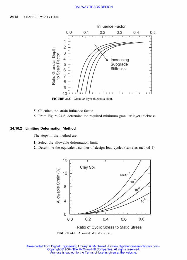
1. Select the allowable strain limit based on design life desired.2. Determine the equivalent number of design load cycles.3. Estimate the static compressive strength of the subgrade soil.4. From Figure 24.5, calculate the allowable cyclic stress.
Any use is subject to the Terms of Use as given at the website.
RAILWAY TRACK DESIGN
RAILWAY TRACK DESIGN 24.19
3. Estimate the static compressive strength of the subgrade soil (same as method 1).4. Calculate the deformation influence factor.5. From a figure similar to Figure 24.6, determine the required minimum granular layer
thickness.
Sections 24.8 and 24.9 indicate the minimum ballast and subballast thickness. The designgranular layer thickness is the greater of (1) the combined ballast and subballast layer min-imum thickness and (2) the thickness required for the subgrade protection.
Some alternatives are available to reduce the settlement in cases where the subgrade isoverstressed. Reducing the wheel load and the total annual traffic million gross tons areassumed to be unacceptable alternatives in most cases. Two general categories may be des-ignated: (1) with the track in place and (2) with the track removed (this would include newconstruction).
24.10.3 Track in Place
With the track remaining in place, there are several options for improving the subgradeperformance:
1. Improve drainage.2. Increase the granular layer thickness.3. Add tensile reinforcement in the subballast (such as geogrid, geoweb).4. Use special on-track machines that can renew substructure conditions while working be-
neath the track.
24.10.4 Track Removed
With the track removed or not yet placed, additional options become available:
1. Install proper drainage.2. Remove soft soils and replace with compacted suitable soils.3. Place impermeable membrane to prevent water from coming into contact with the soil.4. Lime or cement stabilization of soils by mechanical mixing.5. Insert hot mix asphalt concrete layer on subgrade.
Clearly, designing and installing the substructure to meet the track needs without the trackin place is easier and more effective. Obviously many reasons exist why this is not done.
AREMA (2003, chap. 16) recommends a method for determining ballast depth to limitwheel load-induced stress on top of subgrade so that the subgrade will not fail. The methodinvolves determining the depth for a given track modulus and wheel load that results in anallowable pressure of 25 psi. This value applies to all soils. The number of wheel loadrepetitions is not considered in the AREMA method. This is another major deficiency in thismanual. The correct allowable stress at top of subgrade is not constant but depends on thesoil conditions and number of wheel load repetitions. The allowable stress on the top ofsubgrade for good track performance is determined by cumulative deformation (settlement)rather than by bearing capacity. For a mix of traffic the heaviest loads mainly cause thedeformation.
The following are a few examples of subgrade remedial treatment methods to fix theproblems in Table 24.2:
Any use is subject to the Terms of Use as given at the website.
RAILWAY TRACK DESIGN
24.20 CHAPTER TWENTY-FOUR
1. Grouting: Some grouts penetrate the voids of the soils and strengthen them or reducewater seepage. Other grouts compact and reinforce the soils to strengthen them or displacethe soils to compensate for settlement. Jet grouting mixes cement with soil to form col-umns of strengthened soil.
2. Soil mixing: This is a process in which soil is mixed with augers and paddles to createa mixture of soil and cement based grout. Soil mixing creates a column of strengthenedsoil for compression and shear reinforcement.
3. Modification of clay properties with lime: There are several alternatives: quick lime isplaced in boreholes to strengthen the soil; lime is mechanically mixed with soil to formcolumns of material with increased strength; lime and water mixed to form slurry isinjected into clay soil under pressure with the expectation of improving the clay prop-erties. This last is a common but not usually effective treatment with undesirable sideeffects. It fractures the clay instead of penetrating the voids and also solidifies ballast.
4. Reconstruction: Compaction of existing soils in layers at proper water content or substi-tutions of better soils will give improved subgrade. Chemicals such as cement or quickhydrated lime, mechanically mixed with the soils in layers before compaction, will forma stronger or less reactive soil after compaction. The chemistry of the soils should bechecked or tests performed to verify the effectiveness of the treatment, because somecombinations can be harmful. All of these methods generally require removal of the track.
5. Reinforcement: Various plastic grids, metal strips, or cellular materials placed in the soilsgive tensile reinforcement. Alternatively, steel reinforcing can be installed in grout-filledboreholes.
6. Stress reduction: Increasing the thickness of the ballast and subballast will reduce thepressure on the weaker subgrade caused by the train loading. Contrary to the AREMAengineering manual, the allowable pressure is not constant but varies widely and must bedetermined in each case for correct design. The correct strength considers the magnitudeof the repeated loading from the trains and the number of repetitions. For a given axleload, a high-tonnage line would have a much lower apparent strength than a low-tonnageline. Thus, the high-tonnage line needs a greater ballast /subballast thickness for the samesubgrade properties.
24.11 TRACK DRAINAGE
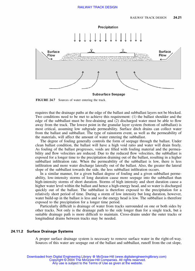
Drainage of railway tracks is essential to achieve acceptable track performance. Water in thetrack substructure originates from three potential sources (Figure 24.7):
1. Precipitation onto the track2. Surface flow from areas adjacent to the track3. Groundwater flow
A complete drainage system must include provisions for handling water from all threesources (Heyns 2000).
24.11.1 Drainage of Precipitation Falling on the Track
Precipitation onto the track will enter the ballast, unless the ballast is highly fouled. Thewater will then flow laterally out of the ballast into the trackside drainage system or enterthe subballast. The water entering the subballast will either drain laterally out of the sub-ballast or continue downward onto the subgrade. The ability of water to drain laterally
Any use is subject to the Terms of Use as given at the website.
RAILWAY TRACK DESIGN
RAILWAY TRACK DESIGN 24.21
FIGURE 24.7 Sources of water entering the track.
requires that the drainage paths at the edge of the ballast and subballast layers not be blocked.Two conditions need to be met to achieve this requirement: (1) the ballast shoulder and theedge of the subballast must be free-draining and (2) discharged water must be able to flowaway from the track. The lowest point in the granular layer system (bottom of subballast) ismost critical, assuming low subgrade permeability. Surface ditch drains can collect waterfrom the ballast and subballast. The type of rainstorm event, as well as the permeability ofthe materials, will affect the amount of water entering the subballast.
The degree of fouling generally controls the form of seepage through the ballast. Underclean ballast condition, the ballast will have a high void ratio and water will drain freely.As fouling of the ballast progresses, voids are filled with fouling material and the permea-bility and flow velocities are reduced. Due to the reduced flow velocities, the subballast isexposed for a longer time to the precipitation draining out of the ballast, resulting in a highersubballast infiltration rate. When the permeability of the subballast is low, there is lessinfiltration and more water discharge laterally out of the ballast. Also, the greater the lateralslope of the subballast towards the side, the less subballast infiltration occurs.
In a similar manner, for a given ballast degree of fouling and a given subballast perme-ability, low-intensity storms of long duration cause more seepage into the subballast thanhigh-intensity storms of short duration. Storms of high intensity and short duration cause ahigher water level within the ballast and hence a high-energy head, and so water is dischargedquickly out of the ballast. The subballast is therefore exposed to the precipitation for arelatively short period of time. During a storm of low intensity but long duration, however,water build-up in the ballast is less and so the energy head is low. The subballast is thereforeexposed to the precipitation for a longer time period.
Particularly difficult is drainage of water from tracks surrounded on one or both sides byother tracks. Not only is the drainage path to the side longer than for a single track, but asuitable drainage path is more difficult to maintain. Cross-drains under the outer tracks orlongitudinal drains between tracks may be needed.
24.11.2 Surface Drainage Systems
A proper surface drainage system is necessary to remove surface water in the right-of-way.Sources of this water are seepage out of the ballast and subballast, runoff from the cut slope,
Any use is subject to the Terms of Use as given at the website.
RAILWAY TRACK DESIGN
24.22 CHAPTER TWENTY-FOUR
and surface runoff from areas adjacent to the track. Open ditches parallel to the track arethe most common component of a surface drainage system. In cuts, ditches parallel to thetrack usually drain water discharged from the cut face as well as lateral discharge out of thetracks.
Ditches on top of cuts should intercept water from drainage basins adjacent to the cutbefore it reaches the cut slopes and divert it to a drainage inlet structure or to a naturalwatercourse nearby. This reduces slope erosion problems and also reduces the required ca-pacity of the trackside ditches. Because the cutoff ditches are placed on top of cuts and areusually not visible from the tracks, they are often overlooked during regular track mainte-nance.
To predict the quantity of surface runoff and lateral discharge out of the tracks that thesystem will need to handle, the rainfall at the site being evaluated needs to be characterized.This is done in terms of frequency of occurrence of a storm of a particular duration andintensity. Intensity-duration-frequency curves can be developed from available meteorologi-cal records for the site. Then an appropriate storm return period needs to be selected. Asthe return period becomes longer, the maximum storm intensity likely to be encountered willincrease. Then the larger the selected return period for design, the smaller the risk of theditch overflowing and causing damage to the tracks, but the higher the cost of the systemto accommodate the larger quantity of water. A design return period of 5 to 10 years istypically appropriate for ditch design.
24.11.3 Considerations for Ditch Design
Ditches parallel to the track are usually unlined and require a high level of maintenance toremove vegetation and sedimentation and to restore the ditch side-slopes where they haveeroded. For the ditches to remain functional and to avoid deposition of sedimentation, alongitudinal minimum slope of 0.5 percent is recommended (Heyns 2000). Ditches placedin long cuts or on flat terrain with the track profile less than the recommended minimumditch slope therefore become deep (and hence far bigger than the required flow capacity) asthey drain towards the outlet. As an alternative, the ditch may be lined to allow placementat a grade shallower than 0.5 percent. For example, smooth-lined concrete ditches can typ-ically be placed at a minimum grade of 0.25 percent.
Stabilization against erosion of ditches is necessary for severe hydraulic conditions. Sta-bilization measures include rigid linings, such as concrete, or flexible linings, such as veg-etation or riprap. Rigid linings are impermeable and are useful in flow zones where highshear stress or nonuniform flow conditions exist, such as at a cut-to-fill transition where theditch outlets onto a high fill. Although rigid linings are nonerodible, they are susceptible tostructural failure. The major causes of such failures are underlying soil movement fromfreeze-thaw cycles, swelling-shrinking cycles, and undermining by water.
24.11.4 Subsurface Drainage Systems
Groundwater flow into the subballast from the subgrade is a problem only in cuts wherewater can enter the ground from higher elevations. This water needs to be intercepted bysubsurface drains to prevent it from weakening the subgrade. However, groundwater alsocan be a problem in level ground when the water table in the track subgrade is within thezone of influence of the train loading 13 feet (4 meters). Subsurface drains can be used tolower this water table and may also be needed to help drain the subballast. An explorationshould be made to estimate the extent and nature of the groundwater in order to design thesubsurface drainage system properly.
A subsurface drainage system is an underground means of collecting gravitational or freewater from the track substructure. Provided that a proper surface drainage system is present,gravitational or free water in the track substructure comes from both precipitation onto the
Any use is subject to the Terms of Use as given at the website.
RAILWAY TRACK DESIGN
RAILWAY TRACK DESIGN 24.23
track and groundwater flow. If a proper surface drainage system is not present, surface flowalso could be a source of subsurface water and must be considered in the design of thedrainage system.
The flow rate of water out of the subballast to a drainage ditch may not be fast enoughto keep the subballast from saturating. Factors causing this include long seepage distance,low permeability of the subballast, and settlement of the subgrade surface causing a depres-sion. In these cases, a subsurface drainage system is appropriate for removing the watertrapped within the subballast.
Subsurface drains that run laterally across the track are classified as transverse drains andare commonly located at right angles to the track centerline. If the ground water flow tendsto be parallel to the track, transverse drains can be more effective than longitudinal drainsin intercepting and/or drawing down the water table. Also, where ballast pockets exist inthe subgrade, transverse drains can be an effective way to drain water from the low locationin the ballast pocket. Transverse systems usually connect to the longitudinal subsurfacesystem or the surface drainage system, such as a ditch.
In a multitrack system the tracks in the center should have lateral subballast slopes thatmatch (or are higher than) the lateral slopes of the outside tracks to allow water to dischargeunder the outside tracks. Where the center tracks are lower than the outside tracks, thegranular layer thickness of the outside tracks can be increased to allow continuous lateraldrainage or a longitudinal drainage system should be placed between the tracks. In eithercase the seepage distance is long, resulting in slow drainage. An alternative would be toinstall transverse drains to carry water from the inside tracks under the outside tracks to adischarge point.
In a multitrack system the path for water to flow to the surface drainage system maybecome very long, even where a proper subballast lateral slope exists. For example, in afour-track system a water particle falling between the center tracks has to drain two trackwidths; thus, drainage may be inadequate. Therefore, it may always be desirable practice todrain water with a proper drainage system between the tracks.
24.12 MAINTENANCE IMPLICATIONS
The decisions made during design and construction of new track have a major effect on thecost of track maintenance. Special attention should be paid to subballast and subgrade drain-age from under the track because they are very difficult to fix after the track is in service.Cutting construction costs on these important components may result in large maintenancecost for years afterwards to compensate for the construction shortcomings.
24.13 ACKNOWLEDGMENTS
Vincent R. Terrill is acknowledged for sharing his extensive railway experience with thewriter over many years, and in particular for his willingness to review the manuscript of thischapter and provide many valuable suggestions.
24.14 REFERENCES
Agarwal, M. M. 1998. Indian Railway Track, 12th ed. New Delhi: Prabha & Co.American Railway Engineering and Maintenance-of-Way Association (AREMA). 2003. Manual for Rail-way Engineering. Landover, MD: AREMA.
Any use is subject to the Terms of Use as given at the website.
RAILWAY TRACK DESIGN
24.24 CHAPTER TWENTY-FOUR
ASTM C295. ‘‘Standard Practice for Petrographic Examination of Aggregates for Concrete.’’ ASTMAnnual Book of Standards, Section 4, Construction, vol. 04.02, Concrete Mineral Aggregates.
ASTM C856. ‘‘Standard Recommended Practice for Petrographic Examination of Hardened Concrete.’’ASTM Annual Book of Standards, Section 4, Construction, vol. 04.02, Concrete and Mineral Aggre-gates.
Esveld, C. 1989. Modern Railway Track. Duisburg: MRT-Productions.Federal Railroad Administration (FRA). 1998. Track Safety Standards, Part 213, Subpart A to F, Class
of Track 1 to 5 and Subpart G for Class of Track 6 and higher. U.S. Department of Transportation,FRA, Washington, DC.
Hay, W. W. 1982. Railroad Engineering, 2nd ed. New York: John Wiley & Sons.Heyns, F. J. 2000. ‘‘Railway Track Drainage Design Techniques.’’ Ph.D. dissertation, University ofMassachusetts, Department of Civil and Environmental Engineering, May.
Kish, A., and G. Samavedam. 1991. ‘‘Dynamic Buckling of Continuous Welded Rail Track: Theory,Tests, and Safety Concepts.’’ Rail-Lateral Track Stability, 1991—Transportation Research Record 1289.
Li, D., and E. T. Selig. 1998. ‘‘Method for Railroad Track Foundation Design: Development’’ and‘‘Method for Railroad Track Foundation Design: Applications.’’ Journal of Geotechnical and Geo-environmental Engineering, ASCE 124(4):316–22 and 323–29.
Marich, S., P. J. Mutton, and G. P. Tew. 1991a. A Review of Track Design Procedures, vol. 1, Rails.Melbourne: BHP Research-Melbourne Labs.
———. 1991b. A Review of Track Design Procedures, vol. 2, Sleepers and Ballast. Melbourne: BHPResearch-Melbourne Labs.
Selig, E. T., and J. M. Waters. 1994. Track Geotechnology and Substructure Management. London:Thomas Telford.
Talbot, A. N. 1933. ‘‘Sixth Progress Report of the Special Committee on Stresses in Track.’’ Bulletin358.