University of British Columbia CPSC 314 Computer Graphics Jan-Apr 2013 Tamara Munzner http://www.ugrad.cs.ubc.ca/~cs314/Vjan2013 Viewing 2 Reading for This Module • FCG Chapter 7 Viewing • FCG Section 6.3.1 Windowing Transforms • RB rest of Chap Viewing • RB rest of App Homogeneous Coords • RB Chap Selection and Feedback • RB Sec Object Selection Using the Back Buffer • (in Chap Now That You Now ) 3 Viewing 4 Using Transformations • three ways • modelling transforms • place objects within scene (shared world) • affine transformations • viewing transforms • place camera • rigid body transformations: rotate, translate • projection transforms • change type of camera • projective transformation
Transcript
University of British Columbia CPSC 314 Computer Graphics
• RB rest of Chap Viewing • RB rest of App Homogeneous Coords
• RB Chap Selection and Feedback • RB Sec Object Selection Using the Back
Buffer • (in Chap Now That You Now )
3
Viewing
4
Using Transformations • three ways
• modelling transforms • place objects within scene (shared world) • affine transformations
• viewing transforms • place camera • rigid body transformations: rotate, translate
• projection transforms • change type of camera • projective transformation
5
Rendering Pipeline
Scene graph Object geometry
Modelling Transforms
Viewing Transform
Projection Transform
6
Scene graph Object geometry
Modelling Transforms
Viewing Transform
Projection Transform
Rendering Pipeline
• result • all vertices of scene in shared
3D world coordinate system
7
Scene graph Object geometry
Modelling Transforms
Viewing Transform
Projection Transform
Rendering Pipeline
• result • scene vertices in 3D view
(camera) coordinate system
8
Scene graph Object geometry
Modelling Transforms
Viewing Transform
Projection Transform
Rendering Pipeline
• result • 2D screen coordinates of
clipped vertices
9
Viewing and Projection
• need to get from 3D world to 2D image • projection: geometric abstraction
• what eyes or cameras do • two pieces
• viewing transform: • where is the camera, what is it pointing at?
• perspective transform: 3D to 2D • flatten to image
10
Rendering Pipeline
Geometry Database
Model/View Transform. Lighting Perspective
Transform. Clipping
Scan Conversion
Depth Test Texturing Blending
Frame- buffer
11
Rendering Pipeline
Geometry Database
Model/View Transform. Lighting Perspective
Transform. Clipping
Scan Conversion
Depth Test Texturing Blending
Frame- buffer
12
OpenGL Transformation Storage • modeling and viewing stored together
• possible because no intervening operations • perspective stored in separate matrix
• specify which matrix is target of operations • common practice: return to default modelview
mode after doing projection operations glMatrixMode(GL_MODELVIEW); glMatrixMode(GL_PROJECTION);
13
Coordinate Systems • result of a transformation • names
• convenience • animal: leg, head, tail
• standard conventions in graphics pipeline • object/modelling • world • camera/viewing/eye • screen/window • raster/device
14
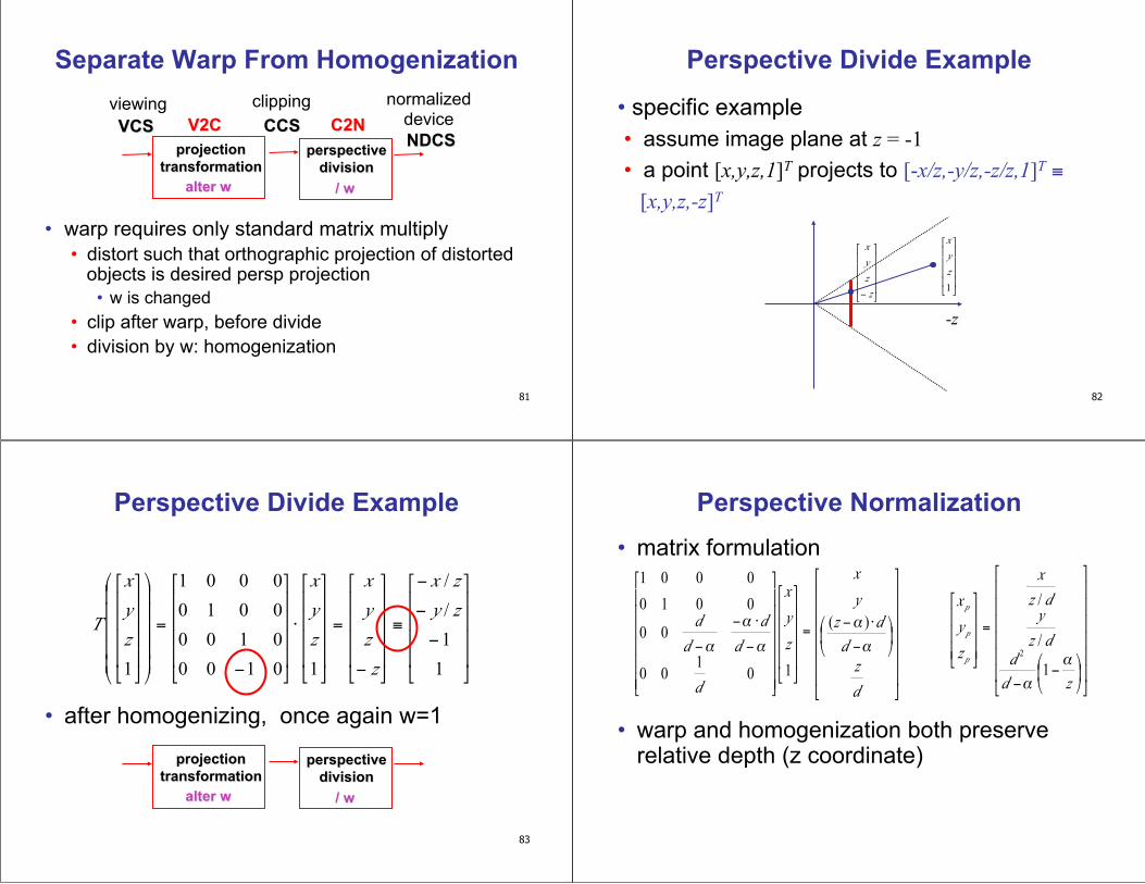
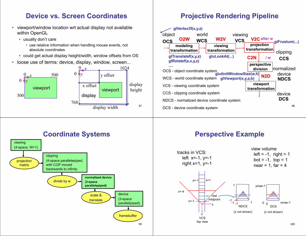
Projective Rendering Pipeline
OCS - object/model coordinate system
WCS - world coordinate system
VCS - viewing/camera/eye coordinate system
CCS - clipping coordinate system
NDCS - normalized device coordinate system
DCS - device/display/screen coordinate system
OCS O2W VCS
CCS
NDCS
DCS
modeling transformation
viewing transformation
projection transformation
viewport transformation
perspective divide
object world viewing
device
normalized device
clipping
W2V V2C
N2D
C2N
WCS
15
Viewing Transformation
OCS WCS VCS modeling
transformation viewing
transformation
OpenGL ModelView matrix
object world viewing
y
x
VCS
Peye z
y x WCS
y
z OCS
image plane
Mmod Mcam
16
Basic Viewing • starting spot - OpenGL
• camera at world origin • probably inside an object
• y axis is up • looking down negative z axis
• why? RHS with x horizontal, y vertical, z out of screen • translate backward so scene is visible
• move distance d = focal length
• where is camera in P1 template code? • 5 units back, looking down -z axis
17
Convenient Camera Motion
• rotate/translate/scale versus • eye point, gaze/lookat direction, up vector
• demo: Robins transformation, projection
18
OpenGL Viewing Transformation
gluLookAt(ex,ey,ez,lx,ly,lz,ux,uy,uz)
• postmultiplies current matrix, so to be safe: glMatrixMode(GL_MODELVIEW); glLoadIdentity(); gluLookAt(ex,ey,ez,lx,ly,lz,ux,uy,uz) // now ok to do model transformations
• demo: Nate Robins tutorial projection
19
Convenient Camera Motion
• rotate/translate/scale versus • eye point, gaze/lookat direction, up vector
Peye
Pref
up view
eye
lookat y
z
x WCS
20
Placing Camera in World Coords: V2W
• treat camera as if it’s just an object • translate from origin to eye • rotate view vector (lookat – eye) to w axis • rotate around w to bring up into vw-plane
y
z
x WCS
v
u
VCS
Peye w
Pref
up view
eye
lookat
21
Deriving V2W Transformation
• translate origin to eye
!
T =
1 0 0 ex
0 1 0 ey
0 0 1 ez
0 0 0 1
"
#
$ $ $ $
%
&
' ' ' '
y
z
x WCS
v
u
VCS
Peye w
Pref
up view
eye
lookat
22
Deriving V2W Transformation • rotate view vector (lookat – eye) to w axis
• w: normalized opposite of view/gaze vector g
!
w = "ˆ g = "g
g
y
z
x WCS
v
u
VCS
Peye w
Pref
up view
eye
lookat
23
Deriving V2W Transformation • rotate around w to bring up into vw-plane
• u should be perpendicular to vw-plane, thus perpendicular to w and up vector t
• v should be perpendicular to u and w
!
u =t "w
t "w
!
v = w " u
y
z
x WCS
v
u
VCS
Peye w
Pref
up view
eye
lookat
24
Deriving V2W Transformation • rotate from WCS xyz into uvw coordinate system with matrix that has
columns u, v, w
• reminder: rotate from uvw to xyz coord sys with matrix M that has columns u,v,w
!
u =t "w
t "w
!
v = w " u
!
w = "ˆ g = "g
g
!
R =
uxvxwx0
uyvywy0
uzvzwz0
0 0 0 1
"
#
$ $ $ $
%
&
' ' ' '
MV2W=TR
!
T=
1 0 0 ex
0 1 0 ey
0 0 1 ez
0 0 0 1
"
#
$ $ $ $
%
&
' ' ' '
25
V2W vs. W2V
• MV2W=TR
• we derived position of camera as object in world • invert for gluLookAt: go from world to camera!
• MW2V=(MV2W)-1=R-1T-1
• inverse is transpose for orthonormal matrices • inverse is negative for translations
!
T"1 =
1 0 0 "ex
0 1 0 "ey
0 0 1 "ez
0 0 0 1
#
$
% % % %
&
'
( ( ( (
!
R"1 =
ux
uy
uz0
vx
vy
vz0
wxwywz0
0 0 0 1
#
$
% % % %
&
'
( ( ( (
!
T=
1 0 0 ex
0 1 0 ey
0 0 1 ez
0 0 0 1
"
#
$ $ $ $
%
&
' ' ' '
!
R =
uxvxwx0
uyvywy0
uzvzwz0
0 0 0 1
"
#
$ $ $ $
%
&
' ' ' '
26
V2W vs. W2V
• MW2V=(MV2W)-1=R-1T-1
!
Mworld2view
=
ux uy uz 0
vx vy vz 0
wx wy wz 0
0 0 0 1
"
#
$ $ $ $
%
&
' ' ' '
1 0 0 (ex0 1 0 (ey0 0 1 (ez0 0 0 1
"
#
$ $ $ $
%
&
' ' ' '
=
ux uy uz (e •u
vx vy vz (e • v
wx wy wz (e •w
0 0 0 1
"
#
$ $ $ $
%
&
' ' ' '
!
MW 2V
=
ux uy uz "ex # ux + "ey # uy + "ez # uzvx vy vz "ex #vx + "ey #vy + "ez #vzwx wy wz "ex #wx + "ey #wy + "ez #wz
0 0 0 1
$
%
& & & &
'
(
) ) ) )
27
Moving the Camera or the World? • two equivalent operations • move camera one way vs. move world other way
• example • initial OpenGL camera: at origin, looking along -z axis • create a unit square parallel to camera at z = -10 • translate in z by 3 possible in two ways
• camera moves to z = -3 • Note OpenGL models viewing in left-hand coordinates
• camera stays put, but world moves to -7 • resulting image same either way
• possible difference: are lights specified in world or view coordinates?
28
World vs. Camera Coordinates Example
W
a = (1,1)W
a
b = (1,1)C1 = (5,3)W
c = (1,1)C2= (1,3)C1 = (5,5)W
C1
b
C2
c
29
Projections I
30
Pinhole Camera
• ingredients • box, film, hole punch
• result • picture
www.kodak.com
www.pinhole.org
www.debevec.org/Pinhole
31
Pinhole Camera
• theoretical perfect pinhole • light shining through tiny hole into dark space
yields upside-down picture
film plane
perfect pinhole
one ray of projection
32
Pinhole Camera
• non-zero sized hole • blur: rays hit multiple points on film plane
film plane
actual pinhole
multiple rays of projection
33
Real Cameras • pinhole camera has small aperture (lens
opening) • minimize blur
• problem: hard to get enough light to expose the film
• solution: lens • permits larger apertures • permits changing distance to film plane
without actually moving it • cost: limited depth of field where image is
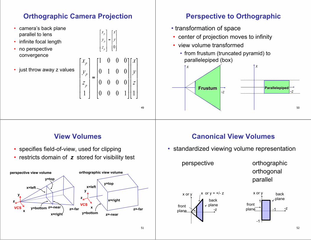
• easier to determine if an arbitrary point is enclosed in volume with canonical view volume vs. clipping to six arbitrary planes
• rendering • projection and rasterization algorithms can be
reused
54
Normalized Device Coordinates
• convention • viewing frustum mapped to specific
parallelepiped • Normalized Device Coordinates (NDC) • same as clipping coords
• only objects inside the parallelepiped get rendered
• which parallelepiped? • depends on rendering system
55
Normalized Device Coordinates
left/right x =+/- 1, top/bottom y =+/- 1, near/far z =+/- 1
-z
x
Frustum
z=-n z=-f
right
left z
x
x= -1 z=1
x=1
Camera coordinates NDC
z= -1
56
Understanding Z
• z axis flip changes coord system handedness • RHS before projection (eye/view coords) • LHS after projection (clip, norm device coords)
x
z
VCS
y x=left
y=top
x=right
z=-far z=-near y=bottom
x
z
NDCS
y
(-1,-1,-1)
(1,1,1)
57
Understanding Z near, far always positive in OpenGL calls glOrtho(left,right,bot,top,near,far); glFrustum(left,right,bot,top,near,far); glPerspective(fovy,aspect,near,far);
orthographic view volume
x
z
VCS
y x=left
y=top
x=right
z=-far z=-near y=bottom
perspective view volume
x=left
x=right
y=top
y=bottom z=-near z=-far x VCS
y
58
Understanding Z
• why near and far plane? • near plane:
• avoid singularity (division by zero, or very small numbers)
• far plane: • store depth in fixed-point representation
(integer), thus have to have fixed range of values (0…1)
• avoid/reduce numerical precision artifacts for distant objects
• transformations that are applied to object first are specified last
OCS1
WCS
VCS
W2O
W2O
CCS clipping
CCS
OCS
104
Reading for Next Time
• RB Chap Color
• FCG Sections 3.2-3.3 • FCG Chap 20 Color • FCG Chap 21.2.2 Visual Perception (Color)
105
Viewing: More Camera Motion
106
Fly "Through The Lens": Roll/Pitch/Yaw
107
Viewing: Incremental Relative Motion • how to move relative to current camera coordinate system?
• what you see in the window • computation in coordinate system used to draw previous
frame is simple: • incremental change I to current C • at time k, want p' = IkIk-1Ik-2Ik-3 ... I5I4I3I2I1Cp
• each time we just want to premultiply by new matrix • p’=ICp
• but we know that OpenGL only supports postmultiply by new matrix
• p’=CIp
108
Viewing: Incremental Relative Motion • sneaky trick: OpenGL modelview matrix has the info we
want! • dump out modelview matrix from previous frame with
glGetDoublev() • C = current camera coordinate matrix
• wipe the matrix stack with glIdentity() • apply incremental update matrix I • apply current camera coord matrix C
• must leave the modelview matrix unchanged by object transformations after your display call • use push/pop
• using OpenGL for storage and calculation • querying pipeline is expensive
• but safe to do just once per frame
109
Caution: OpenGL Matrix Storage
• OpenGL internal matrix storage is columnwise, not rowwise a e i m b f j n c g k o d h l p • opposite of standard C/C++/Java convention • possibly confusing if you look at the matrix
from glGetDoublev()!
110
Viewing: Virtual Trackball
• interface for spinning objects around • drag mouse to control rotation of view volume
• orbit/spin metaphor • vs. flying/driving
• rolling glass trackball • center at screen origin, surrounds world • hemisphere “sticks up” in z, out of screen • rotate ball = spin world
111
Clarify: Virtual Trackball
• know screen click: (x, y, 0) • want to infer point on trackball: (x,y,z)
• ball is unit sphere, so ||x, y, z|| = 1.0 • solve for z
eye
image plane
y
z
(x, y, 0)
112 y
z
Clarify: Trackball Rotation • user drags between two points on image plane
• mouse down at i1 = (x, y), mouse up at i2 = (a, b) • find corresponding points on virtual ball
• p1 = (x, y, z), p2 = (a, b, c)
• compute rotation angle and axis for ball • axis of rotation is plane normal: cross product p1 x p2
• amount of rotation θ from angle between lines • p1 • p2 = |p1| |p2| cos θ
i1 = (x, y)
i2 = (a, b)
screen plane
screen plane
virtual ball hemisphere
113
Clarify: Trackball Rotation • finding location on ball corresponding to click on image
plane • ball radius r is 1
z
r=1 z
screen plane
d
virtual ball hemisphere (x, y)
d
(width/2, height/2) screen plane
(x, y, z)
(x, y)
114
Trackball Computation • user defines two points
• place where first clicked p1 = (x, y, z) • place where released p2 = (a, b, c)
• create plane from vectors between points, origin • axis of rotation is plane normal: cross product
• (p1 - o) x (p2 - o): p1 x p2 if origin = (0,0,0) • amount of rotation depends on angle between
lines • p1 • p2 = |p1| |p2| cos θ • |p1 x p2 | = |p1| |p2| sin θ
• compute rotation matrix, use to rotate world
115
Picking
116
Reading
• Red Book • Selection and Feedback Chapter
• all • Now That You Know Chapter
• only Object Selection Using the Back Buffer
117
Interactive Object Selection • move cursor over object, click
• how to decide what is below? • inverse of rendering pipeline flow
• from pixel back up to object • ambiguity
• many 3D world objects map to same 2D point • four common approaches
• manual ray intersection • bounding extents • backbuffer color coding • selection region with hit list
118
Manual Ray Intersection • do all computation at application level
• map selection point to a ray • intersect ray with all objects in scene.
• advantages • no library dependence
• disadvantages • difficult to program • slow: work to do depends on total number and
complexity of objects in scene
x VCS
y
119
Bounding Extents • keep track of axis-aligned bounding
rectangles
• advantages • conceptually simple • easy to keep track of boxes in world space
120
Bounding Extents • disadvantages
• low precision • must keep track of object-rectangle relationship
• extensions • do more sophisticated bound bookkeeping
• first level: box check. • second level: object check
121
Backbuffer Color Coding
• use backbuffer for picking • create image as computational entity • never displayed to user
• redraw all objects in backbuffer • turn off shading calculations • set unique color for each pickable object
• store in table • read back pixel at cursor location
• use small region around cursor for viewport • assign per-object integer keys (names) • redraw in special mode • store hit list of objects in region • examine hit list
• OpenGL support
125
Viewport
• small rectangle around cursor • change coord sys so fills viewport
• why rectangle instead of point? • people aren’t great at positioning mouse
• Fitts’ Law: time to acquire a target is function of the distance to and size of the target
• allow several pixels of slop 126
• nontrivial to compute • invert viewport matrix, set up new orthogonal
projection • simple utility command
• gluPickMatrix(x,y,w,h,viewport) • x,y: cursor point • w,h: sensitivity/slop (in pixels)
• push old setup first, so can pop it later
Viewport
127
Render Modes
• glRenderMode(mode)
• GL_RENDER: normal color buffer • default
• GL_SELECT: selection mode for picking
• (GL_FEEDBACK: report objects drawn)
128
Name Stack
• again, "names" are just integers glInitNames() • flat list glLoadName(name) • or hierarchy supported by stack glPushName(name), glPopName