22
. Micah Li PhD EM Application Engineer Flomerics U.K. [email protected] RCS Computation, Reduction and Stealth Design
| Date post: | 20-Apr-2018 |
| Category: |
Documents |
| Upload: | truongtuong |
| View: | 217 times |
| Download: | 2 times |
.
Micah Li PhD
EM Application EngineerFlomerics U.K.
RCS Computation, Reduction and Stealth Design
.
Agenda
� Introduction� Background of TLM (MICROSTRIPES) � Numerically predicting the radar signature
– Luneberg Lens reflector example
� Reduction and stealth design� Conclusions
.
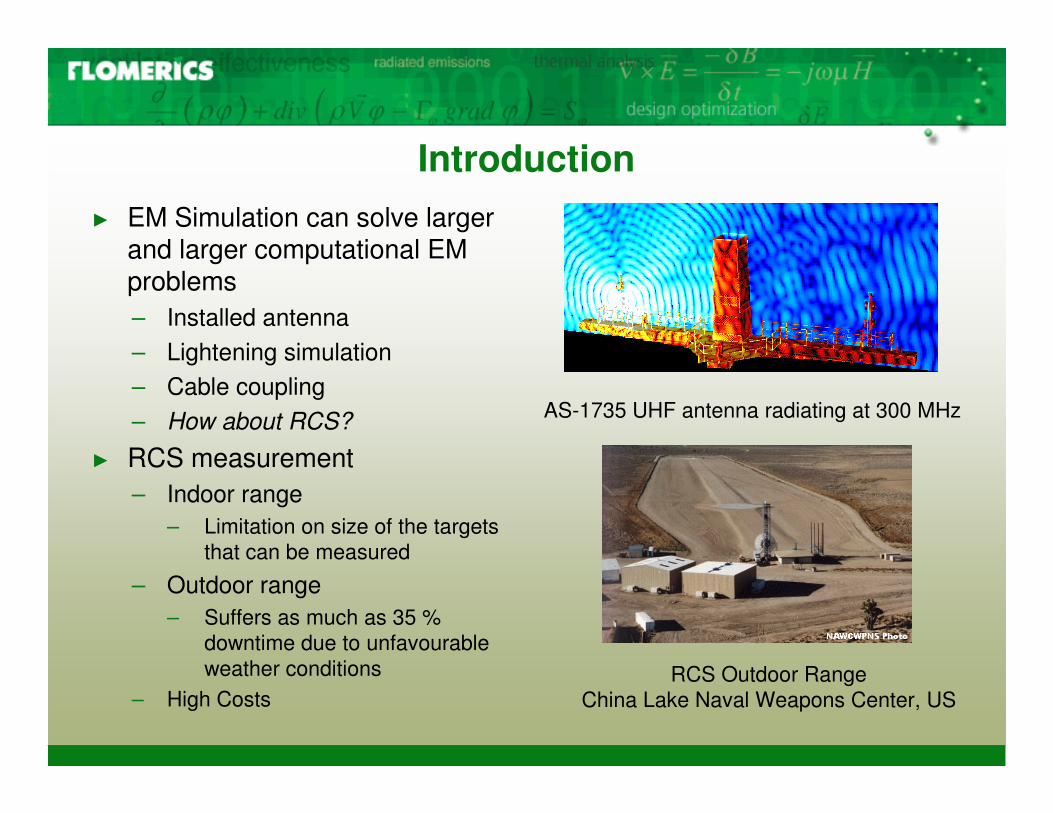
Introduction� EM Simulation can solve larger
and larger computational EM problems – Installed antenna– Lightening simulation– Cable coupling– How about RCS?
� RCS measurement – Indoor range
– Limitation on size of the targets that can be measured
– Outdoor range– Suffers as much as 35 %
downtime due to unfavourable weather conditions
– High CostsRCS Outdoor Range
China Lake Naval Weapons Center, US
AS-1735 UHF antenna radiating at 300 MHz
.
Modelling Radar Cross Section (RCS)
� How simulation can help on modelling RCS– Provides flexibility in design procedure– Shorten the time from idea to design– Visibility of performance matrix
� Requirements for EM simulation tool– Accuracy & speed– Capable of handling electrical big structures– CAD import capability
.
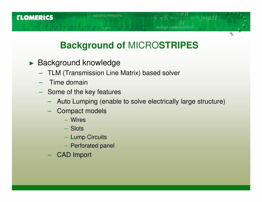
Background of MICROSTRIPES
� Background knowledge – TLM (Transmission Line Matrix) based solver– Time domain– Some of the key features
– Auto Lumping (enable to solve electrically large structure)– Compact models
– Wires – Slots– Lump Circuits– Perforated panel
– CAD Import
.
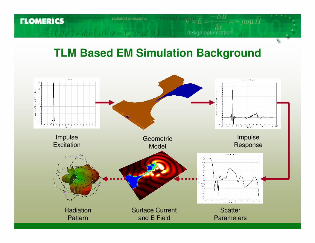
TLM Based EM Simulation Background
Geometric Model
Impulse Excitation
Impulse Response
Surface Current and E Field
Scatter Parameters
Radiation Pattern
.
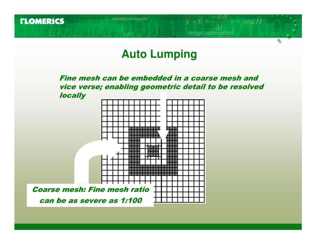
Auto Lumping
���������������������������� ��������������������������������� ������������� ������� ������ ���
� ����������������������� �
���������������������
.
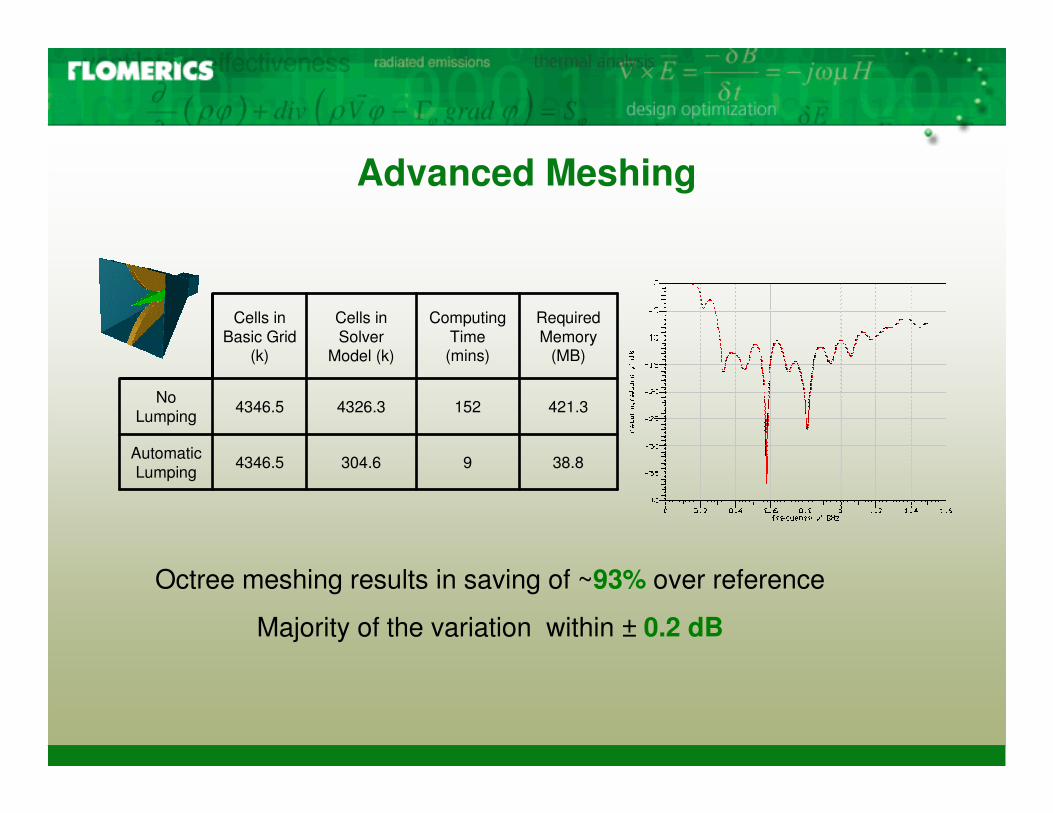
Advanced Meshing
Octree meshing results in saving of ~93% over reference
Majority of the variation within ± 0.2 dB
38.89304.64346.5Automatic Lumping
421.31524326.34346.5No Lumping
Required Memory
(MB)
Computing Time
(mins)
Cells in Solver
Model (k)
Cells in Basic Grid
(k)
.
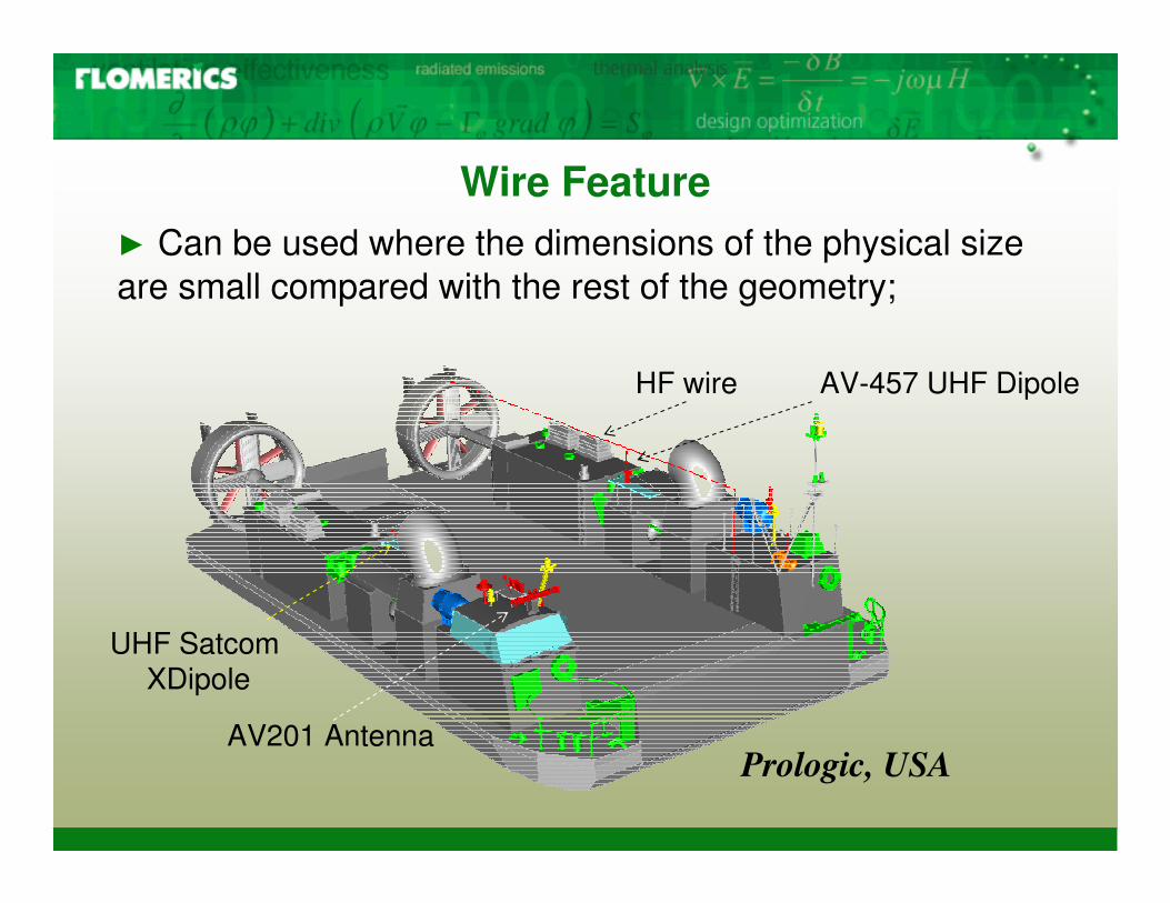
Wire Feature� Can be used where the dimensions of the physical size are small compared with the rest of the geometry;
HF wire AV-457 UHF Dipole
UHF SatcomXDipole
AV201 AntennaPrologic, USA
.
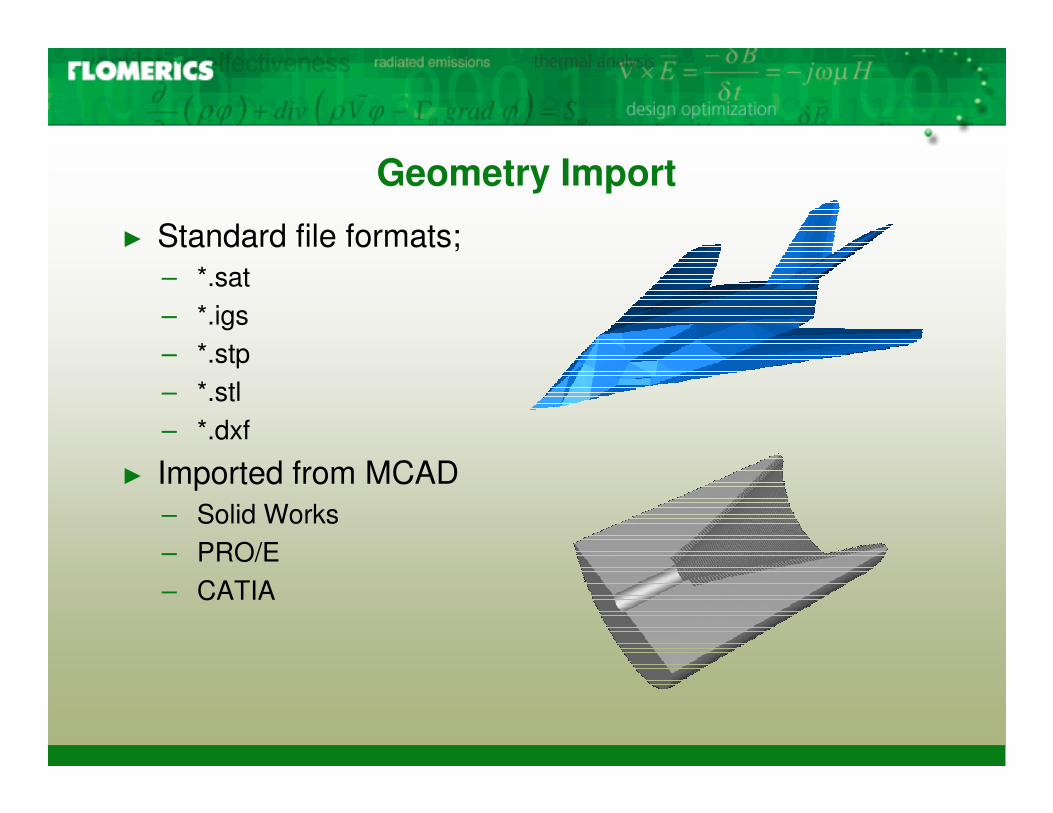
Geometry Import
� Standard file formats;– *.sat– *.igs– *.stp– *.stl– *.dxf
� Imported from MCAD– Solid Works– PRO/E– CATIA
.
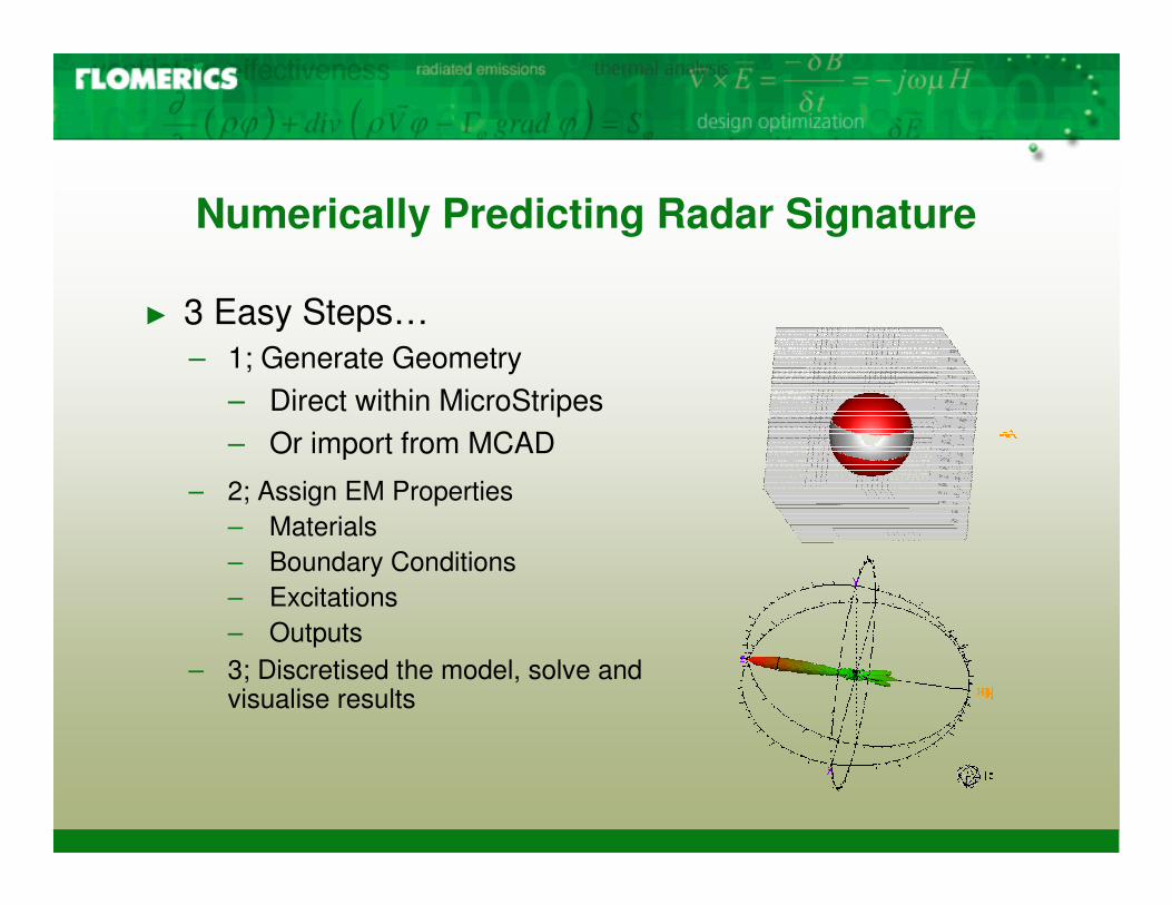
Numerically Predicting Radar Signature
� 3 Easy Steps…– 1; Generate Geometry
– Direct within MicroStripes– Or import from MCAD
– 2; Assign EM Properties– Materials– Boundary Conditions– Excitations– Outputs
– 3; Discretised the model, solve and visualise results
.
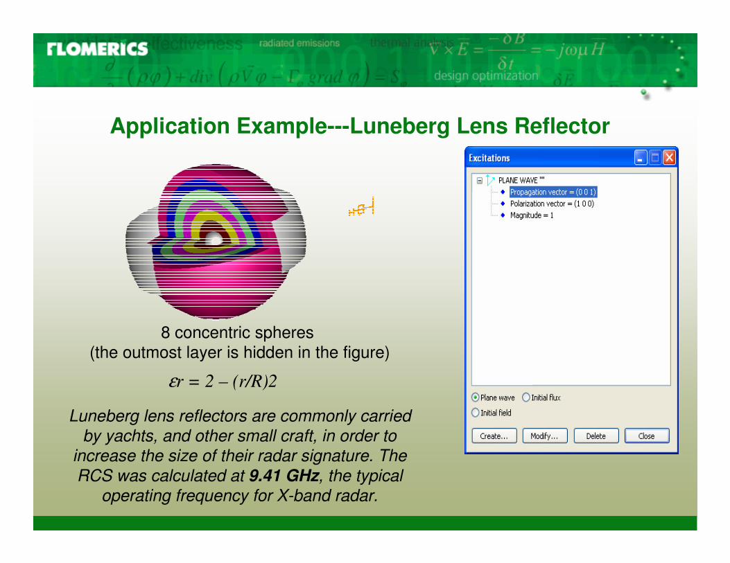
Application Example---Luneberg Lens Reflector
8 concentric spheres(the outmost layer is hidden in the figure)
εr = 2 – (r/R)2
Luneberg lens reflectors are commonly carried by yachts, and other small craft, in order to
increase the size of their radar signature. The RCS was calculated at 9.41 GHz, the typical
operating frequency for X-band radar.
.
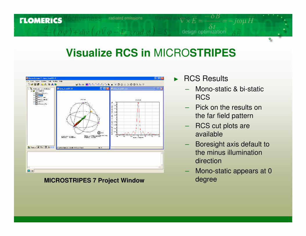
Visualize RCS in MICROSTRIPES
� RCS Results – Mono-static & bi-static
RCS – Pick on the results on
the far field pattern– RCS cut plots are
available– Boresight axis default to
the minus illumination direction
– Mono-static appears at 0 degree MICROSTRIPES 7 Project Window
.
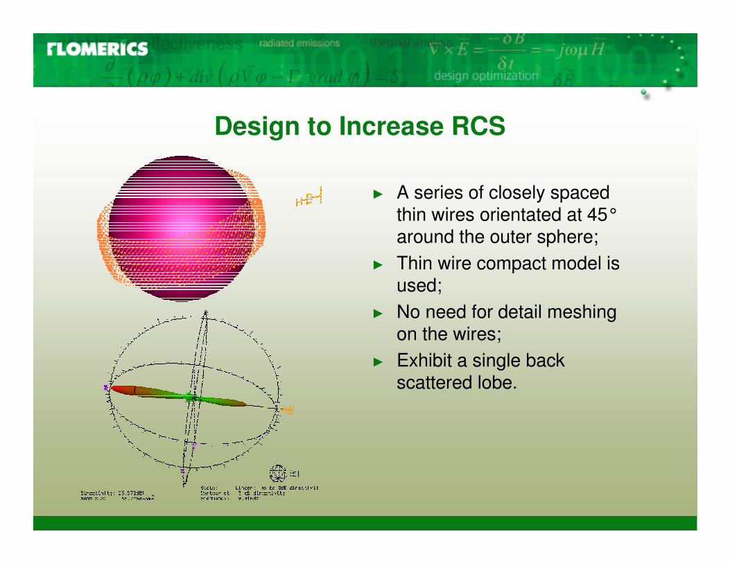
Design to Increase RCS
� A series of closely spaced thin wires orientated at 45°around the outer sphere;
� Thin wire compact model is used;
� No need for detail meshing on the wires;
� Exhibit a single back scattered lobe.
.
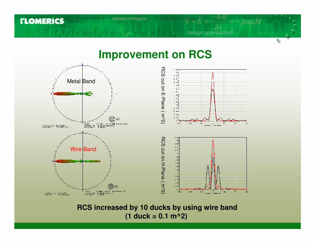
Improvement on RCS
Metal Band
Wire BandR
CS
cut on E-P
lane ( m^2)
RC
S cut on H
-Plane ( m
^2)
RCS increased by 10 ducks by using wire band(1 duck = 0.1 m^2)
.
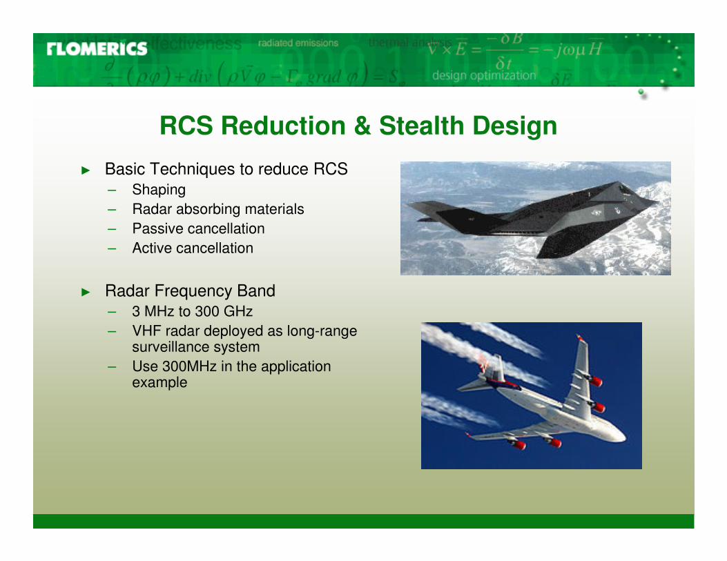
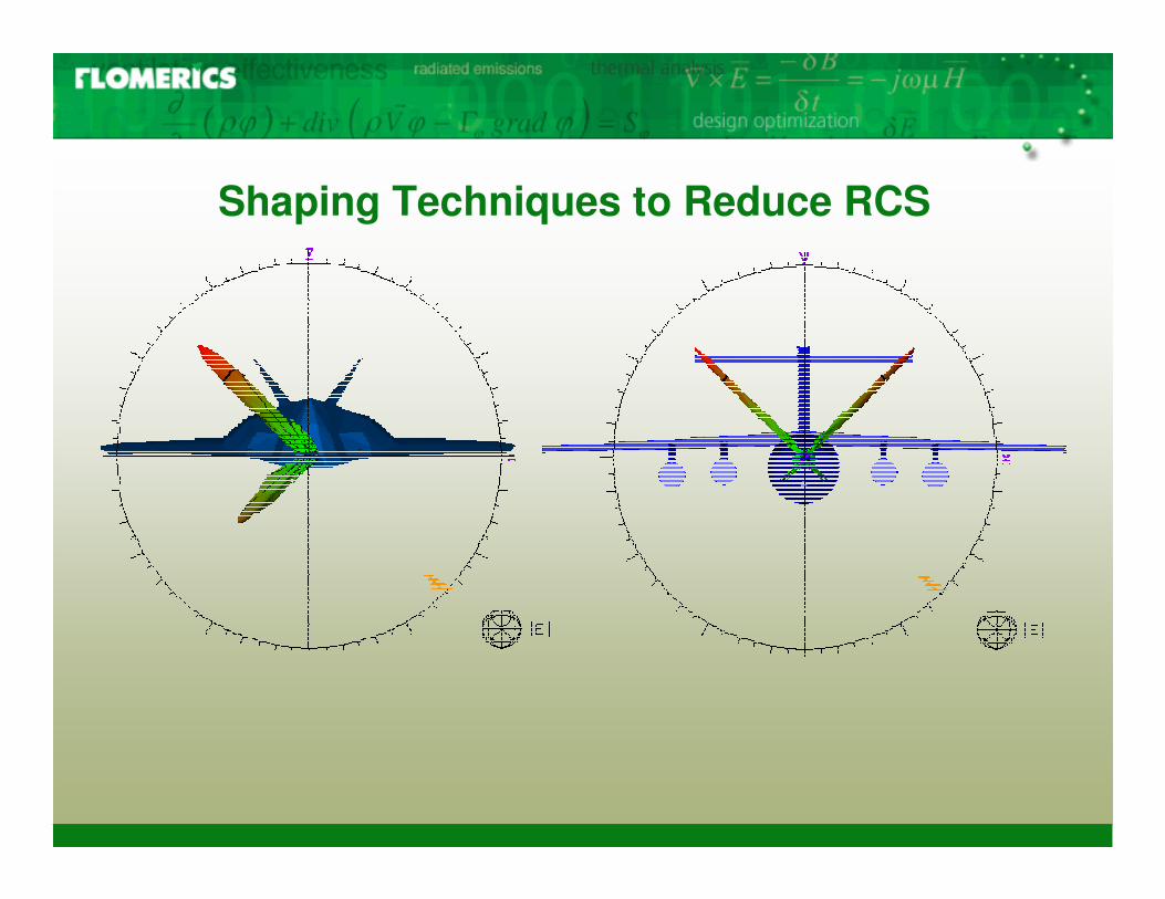
RCS Reduction & Stealth Design� Basic Techniques to reduce RCS
– Shaping– Radar absorbing materials– Passive cancellation– Active cancellation
� Radar Frequency Band– 3 MHz to 300 GHz– VHF radar deployed as long-range
surveillance system– Use 300MHz in the application
example
.
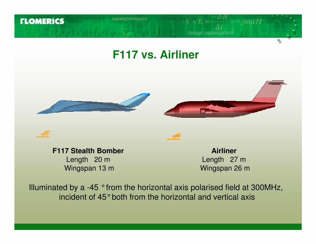
F117 vs. Airliner
Airliner Length 27 m Wingspan 26 m
F117 Stealth BomberLength 20 m Wingspan 13 m
Illuminated by a -45 °from the horizontal axis polarised field at 300MHz, incident of 45°both from the horizontal and vertical axis
.
Shaping Techniques to Reduce RCS
.
RC
S cut on E
-Plane ( m
^2)
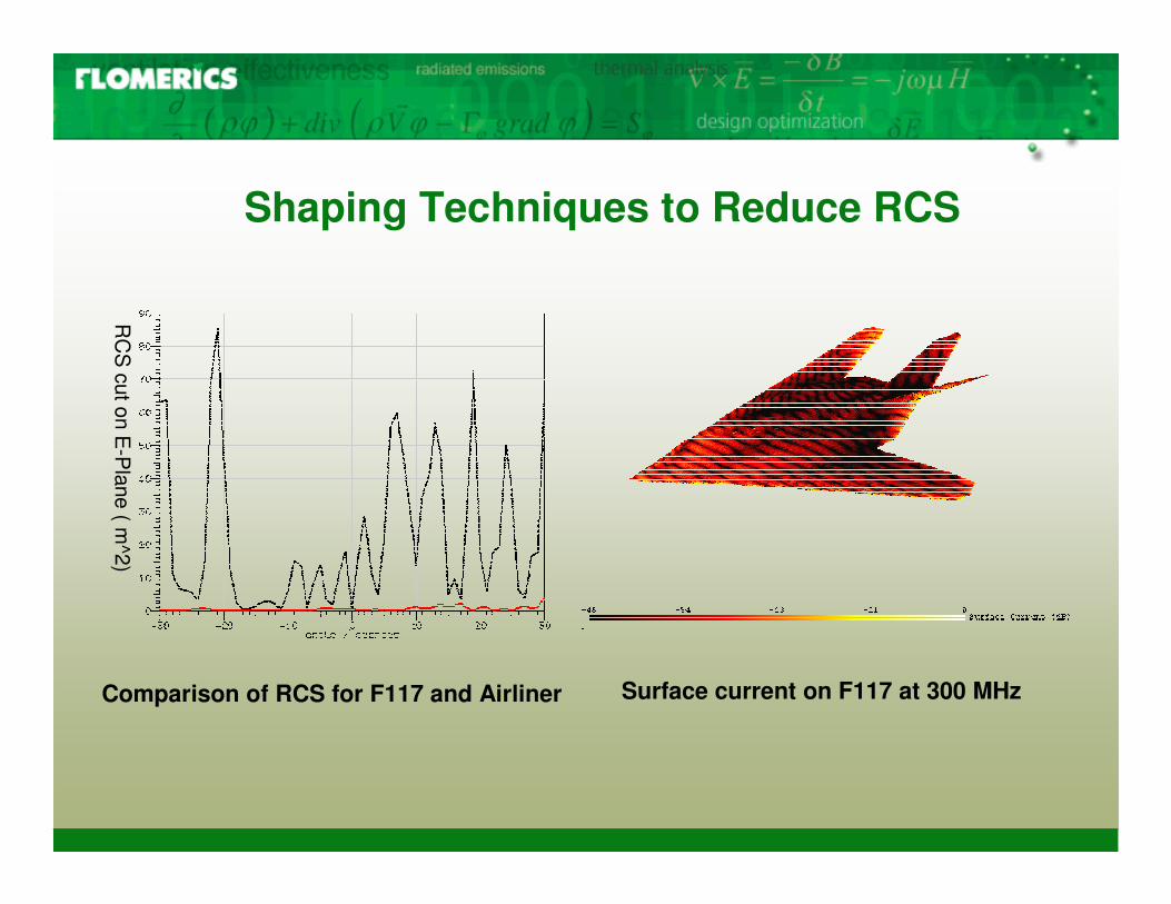
Shaping Techniques to Reduce RCS
Comparison of RCS for F117 and Airliner Surface current on F117 at 300 MHz
.
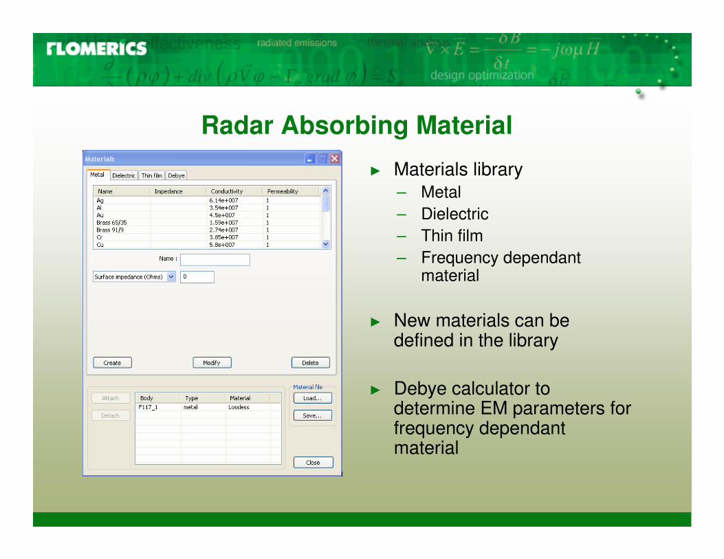
Radar Absorbing Material
� Materials library– Metal– Dielectric– Thin film– Frequency dependant
material
� New materials can be defined in the library
� Debye calculator to determine EM parameters for frequency dependant material
.
Conclusions
� 3D EM modelling is an efficient method for RCS computation and stealth design;
� It reduces the cost and time for prototyping RCS products;
� Steps to compute the mono-static and bi-static RCS have been discussed in the presentation;
� EM modelling has constraints on the electrical size of the model
.
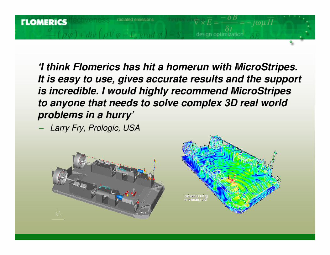
‘I think Flomerics has hit a homerun with MicroStripes. It is easy to use, gives accurate results and the support is incredible. I would highly recommend MicroStripes to anyone that needs to solve complex 3D real world problems in a hurry’– Larry Fry, Prologic, USA


