700 K STREET, N.W. WASHINGTON, D.C. 20001 TEL +1 202.639.7700 FAX +1 202.639.7890 BakerBotts.com AUSTIN BEIJING BRUSSELS DALLAS DUBAI HONG KONG HOUSTON LONDON MOSCOW NEW YORK PALO ALTO RIYADH SAN FRANCISCO WASHINGTON Jay T. Ryan TEL: 2026397789 FAX: 2025851015 [email protected]January 15, 2021 Christopher Lawrence Office of Electricity OE-20, Room 8E-0 United States Department of Energy 1000 Independence Avenue, S.W. Washington, D.C. 20585 RE: CHPE LLC OE Docket No. PP-481 Supplement to Pending Application of CHPE LLC to Amend Presidential Permit No. 481 Dear Mr. Lawrence: On September 25, 2020, CHPE LLC (CHPE) filed an application with the U.S. Department of Energy (DOE) to amend Presidential Permit No. PP-481 (Amendment Application) to incorporate proposed changes to the permitted route for the Champlain Hudson Power Express Project (Project). The Project, as currently permitted, is a 336-mile, 1000 megawatt (MW), high-voltage direct current underwater and underground merchant transmission line that will extend from the United States-Canada border south into New York City. Notice of the Amendment Application appeared in the Federal Register on October 5, 2020 and the public comment period concluded November 4, 2020. DOE has not yet acted on the Amendment Application. Since the filing of the Amendment Application last September, the New York Independent System Operator (NYISO) completed a System Reliability Impact Study (SRIS) that assessed the potential impact of increasing the Project’s transmission capacity from 1,000 MW to 1,250 MW. The SRIS determined that the Project can interconnect and operate at 1,250 MW without adversely affecting the reliability of the interstate transmission grid. In addition to the completed SRIS, an expert retained by CHPE completed an analysis of the potential impacts
On September 25, 2020, CHPE LLC (CHPE) filed an application with the U.S.
Department of Energy (DOE) to amend Presidential Permit No. PP-481 (Amendment
Application) to incorporate proposed changes to the permitted route for the Champlain Hudson
Power Express Project (Project). The Project, as currently permitted, is a 336-mile, 1000
megawatt (MW), high-voltage direct current underwater and underground merchant transmission
line that will extend from the United States-Canada border south into New York City.
Notice of the Amendment Application appeared in the Federal Register on October 5,
2020 and the public comment period concluded November 4, 2020. DOE has not yet acted on
the Amendment Application.
Since the filing of the Amendment Application last September, the New York
Independent System Operator (NYISO) completed a System Reliability Impact Study (SRIS)
that assessed the potential impact of increasing the Project’s transmission capacity from 1,000
MW to 1,250 MW. The SRIS determined that the Project can interconnect and operate at 1,250
MW without adversely affecting the reliability of the interstate transmission grid. In addition to
the completed SRIS, an expert retained by CHPE completed an analysis of the potential impacts
2
of operating a 1,250 MW transmission line. This analysis, which addressed magnetic fields,
compass deviations, and thermal cable losses, determined there would be no material change in
impacts beyond those identified for the permitted 1,000 MW project.
Based on this new information, CHPE is supplementing the pending Amendment
Application with an additional request that PP-481 be amended to allow CHPE to construct,
operate, maintain, and connect a 1,250 MW transmission line (Supplement). As discussed in the
Supplement, increasing the Project’s transmission capacity will not require any material changes
to the construction methods previously analyzed by DOE. Similarly, there will be no material
changes to the operation and maintenance of the Project.
CHPE is enclosing an original and two (2) copies of the Supplement, and requests that it
be incorporated into the Amendment Application which was filed in accordance with Executive
Order 10485, as amended by Executive Order 12038, and DOE’s implementing regulations, 10
C.F.R. § 205.320 et seq. As required by DOE’s regulations, the Supplement includes technical
information regarding the proposed upgrade to 1,250 MW and an analysis of the associated
environmental impacts. The SRIS, which contains critical energy infrastructure information, will
be transmitted directly to DOE by NYISO.
Please do not hesitate to contact me if you have any questions regarding this matter.
Sincerely,
/s/ Jay Ryan
Jay Ryan
cc: Melissa Pauley, DOE
Josh Bagnato, TDI
Bill Helmer, TDI
Sean Murphy, VHB
John Katz, FERC
Brian Ossias, New York Department of Public Service
UNITED STATES OF AMERICA
BEFORE THE DEPARTMENT OF ENERGY
OFFICE OF ELECTRICITY DELIVERY AND
ENERGY RELIABILITY
CHPE LLC
Docket No. PP-481
SUPPLEMENT TO PENDING APPLICATION OF CHPE LLC
TO AMEND PRESIDENTIAL PERMIT NO. 481
January 15, 2021
2
UNITED STATES OF AMERICA
BEFORE THE DEPARTMENT OF ENERGY
OFFICE OF ELECTRICITY DELIVERY AND
ENERGY RELIABILITY
) CHPE LLC ) OE DOCKET NO. PP-481 )
SUPPLEMENT TO PENDING APPLICATION OF CHPE, LLC TO AMEND PRESIDENTIAL PERMIT NO. 481
On September 25, 2020, CHPE LLC (CHPE) filed an application with the U.S. Department
of Energy (DOE) to amend Presidential Permit No. PP-481 (Amendment Application) to
incorporate proposed changes to the permitted route for the Champlain Hudson Power Express
Project (Project). The Project, as currently permitted, is a 336-mile, 1000 megawatt (MW), high-
voltage direct current underwater and underground merchant transmission line that will extend
from the United States-Canada border south into New York City. The Amendment Application
was filed pursuant to Executive Order 10485, as amended by Executive Order 12038, and
applicable regulations of the United States Department of Energy (DOE), 10 C.F.R. §§ 205.320 et
seq. CHPE is filing this supplement to the pending Amendment Application to request that DOE
also amend PP-481 to authorize CHPE to construct, operate, maintain, and connect the Project as
a 1,250 MW transmission line (Supplement). As discussed herein, upgrading the Project’s
capacity will not adversely affect the reliability of the interstate transmission grid and there will
be no material changes in the environmental impacts beyond those already identified and analyzed
3
in DOE’s Final Environmental Impact Statement for the Champlain Hudson Power Express
Transmission Line Project (DOE/EIS-0447).
BACKGROUND
On October 6, 2014, DOE issued a Presidential Permit (PP-362) authorizing Champlain
Hudson Power Express Inc. (CHPEI) to construct, operate, and maintain the Project. The aquatic
segments of the transmission line will primarily be submerged in and/or under Lake Champlain
and the Hudson, Harlem, and East Rivers. The terrestrial portions of the transmission line will
primarily be buried in existing road and railroad rights-of-way (ROW).
On April 6, 2020, CHPEI and CHPE LLC jointly filed an application with DOE requesting
that DOE amend or, in the alternative, rescind and reissue Presidential Permit No. PP-362 to enable
the transfer of the permit from CHPEI to its affiliate CHPE LLC. In response to the joint
application, DOE issued Presidential Permit No. 481 to CHPE LLC on July 21, 2020.
On September 25, 2020, the CHPE LLC filed the Amendment Application requesting that
DOE amend Presidential Permit PP-481 to incorporate certain modifications to the permitted route
and the location of the converter station. These modifications were developed in consultation with
various stakeholders and are principally driven by environmental, landowner/stakeholder, and
engineering considerations that have been identified as the Applicant has refined the design of the
Project. The Applicant also proposed a new construction method that will reduce environmental
impacts.
While working with HVDC equipment manufacturers to finalize the design of the Project,
the Applicants were made aware of continuing advances in the design of HVDC cables that allow
for increased transmission capacity with no significant change in cable size. Additionally, the
4
New York Independent System Operator (NYISO) recently completed a System Reliability Impact
Study (SRIS) finding that the Project can interconnect at 1,250 MW without adversely affecting
the reliability of the interstate transmission grid. Applicant also retained an expert to assess the
potential environmental impacts of the 250 MW upgrade; the expert determined that operating a
1,250 MW transmission line would not have impacts materially different than those previously
identified and assessed by DOE. The discussion below summarizes this new information and
provides the basis upon which DOE can approve the requested 250 MW increase in the Project’s
capacity.
PROPOSED ADDITIONAL MODIFICATION
As currently permitted, CHPE LLC is authorized to construct, operate, and maintain a
1,000 MW transmission line. The Applicant seeks to amend PP-481 to authorize CHPE LLC to
construct, operate and maintain a 1,250 MW transmission line (Proposed Modification).
To implement the Proposed Modification, no changes to the construction and operation
activities as previously described in the administrative record in this proceeding (Project
Documentation) are necessary. Additionally, the design of the upland and submarine cables for
the Proposed Modification are consistent with those provided in the Project Documentation. The
conductor design, which consists of copper wires surrounded by a conductor shield, insulation,
metallic shield / sheath, moisture barrier, and jacket / outer sheath, is unchanged. The submarine
cables will continue to have armoring for additional protection.
The mechanical properties of the proposed cables are also similar to the cables as
permitted. As shown in the table below, the diameter of the proposed cables does not necessitate
5
any modifications to the previously approved overland or in-water installation, including the width
of trenches as described in the Project Documentation.
Permitted Transmission System
HVDC Cables
Proposed Transmission System
HVDC Cables Delta
Capacity (MW) 1,000 1,250 25%
Rated Continuous Voltage (kV) 320 400 25%
Rated Continuous Current Under Installation Conditions (Amps)
1638 1638 0
Overland Cables
Diameter 4.72 in (119.96 mm) 4.86 in (123.53 mm) 3.0%
Weight in Air 20.7 lbs/ft (30.7 kg/m) 21.1 lbs/ft (31.4 kg/m) 2.1%
Submarine Cables
Diameter 5.24 in (133 mm) 5.36 in (137.3 mm) 3.2%
Weight in Air 34.9 lbs/ft (51.9 kg/m) 35.9 lbs/ft (53.4 kg/m) 2.9%
Weight in Water 26.9 lbs/ft (40 kg/m) 26.4 lbs/ft (39.3 kg/m) -1.8%
Due to the similarities of the proposed HVDC cables to those previously considered, there
will be no changes in the construction and operation of the Project as described in the Project
Documentation. For the terrestrial portions of the Project route, the underground HVDC cables
will still be buried via excavated trenches or Horizontal Directional Drilling (HDD) methods.
There also will be no changes to the initial clearing, trench excavation, backfilling, and restoration
and revegetation activities as described in the Project Documentation. The proposed HVAC cables
are also similar enough to those previously analyzed so there will be no changes in the construction
and operation of the Project as described in the Project Documentation.
6
For underwater cable installation, the primary methods for installation will still be jet-
plowing and shear plowing, with shoreline transitions completed by HDD. The HVDC submarine
cables will continue to be bundled together when installed within the water bodies either by jet-
plow or shear-plow techniques. The slight decrease of the in-water weight of the submarine cables
is not expected to substantially impact the expected depth of self-burial of the cables in the deeper
waters of Lake Champlain, where the cables will be placed on the lake bottom. The installation
vessels used for in-water construction will remain the same as those described in Project
Documentation.
HVAC cables extending from the Astoria East substation to the Rainey substation will be
installed using techniques that remain unchanged from those described in the Project
Documentation. To accommodate the additional 250 MW, the design of this HVAC system has
been altered such that there are now two conductors per phase proposed instead of one conductor
per phase. The outcome of this change is a different configuration of the AC system underground,
but no changes above ground. A typical diagram showing the new HVAC configuration is included
as Appendix A.
In the Project Documentation, the converter station is described as a “compact type” with
a total footprint (i.e., building and associated footprint) of approximately four-and-a-half (4.5)
acres. The converter station to support the Proposed Modification would occupy a total footprint
of approximately 5.5 acres, which represents a minor increase in the necessary area given the
available land in the vicinity.
7
INFORMATION REGARDING THE APPLICANT1
No updates or changes to the information regarding the Applicant are necessitated by this
Supplement to the Amendment Application. The information regarding the Applicant previously
provided to DOE, as incorporated into the Amendment Application, remains current and correct.
BULK POWER SYSTEM INFORMATION2
In accordance with applicable NYISO tariff requirements, as approved by the Federal
Energy Regulatory Commission, Applicant submitted an interconnection request (NYISO Queue
Position #887) for an additional 250 MW injection at the Point of Interconnection at the New
York Power Authority’s Astoria Annex 345 kV substation. In response to the interconnection
request, NYISO completed an “Interconnection System Reliability Impact Study for the NYISO
Q887: CH Uprate Project.” The SRIS, which will be forwarded directly to DOE by NYISO,
concluded that:
The Project will be operated in accordance with all NYISO requirements;
The Project will be designed in accordance with all applicable reliability
standards; and
The Project will not adversely impact the reliability of the New York State
Transmission System.
NYISO’s conclusions were based on, among other things, steady state, short circuit, and stability
analyses. On December 10, 2020, the NYISO Operating Committee approved the SRIS.3
1 See10 C.F.R. § 205.322(a). 2 See10 C.F.R. § 205.322(b). 3 See Attachment C (copy of minutes from the December 10, 2020 NYISO Operating Committee meeting).
8
ENVIRONMENTAL ANALYSIS
A. Introduction
Set forth below is an analysis of potential environmental impacts associated with upgrading
the Project’s capacity from 1,000 MW to 1,250 MW. The analysis includes a comparison of the
impacts to those previously analyzed by DOE in DOE/EIS-0447. DOE’s approval of the
modifications to the routing and the location of the converter station as requested in the
Amendment Application will have no bearing on the environmental impacts associated with this
Proposed Modification.
B. Resource Areas with No Change
The Applicant reviewed the environmental resource areas that were considered in the EIS.
The Proposed Modification will not have any substantive effect on certain resources and there is
no new information that would suggest there are impacts that were not considered in the EIS to
these resources. These resources are discussed below, as well as the rationale for excluding them
from a more detailed analysis.
Land Use
The EIS evaluated potential impacts to land use resources related to the construction and
operation of the Project and concluded that during construction there would be temporary, non-
significant disruption of normal routines due to access limitations from presence of construction
activities. During operations, there would be a potential for restrictions to allow for operations
and maintenance.
The Proposed Modification would not substantively change the affected environment for
land use as described in Sections 3.1.1, 3.2.1, 3.3.1 and 3.4.1 of the EIS. The Proposed
Modification would impact the same land uses as those considered in the EIS and there would be
9
no change in the trench or, as proposed in the Amendment Application, conduit design. The
converter station associated with the modification will occupy 1 acre of additional area than had
been considered in the EIS but still be within the same industrialized location that was discussed
in the EIS. The Applicant would employ the same impact avoidance and minimization measures,
including BMPs, described in Section G.1 of Appendix G in the EIS, such as engaging a qualified
Agricultural Inspector and proper site restoration. There would be no additional land use issues for
the Proposed Modification over those considered in the EIS.
Transportation and Traffic
The EIS evaluated potential impacts to transportation and traffic related to the Project and
concluded there would be non-significant disruptions to navigation, railroad operations, and traffic
flow, as well as commercial and recreational transportation uses, during construction. The EIS
also evaluated the impacts associated with anchor snag during operation of the Project.
The Proposed Modification would not substantively change the affected environment for
transportation and traffic as described in Sections 3.1.2, 3.2.2, 3.3.2, and 3.4.2 of the EIS. The
Proposed Modification would impact the same overland (e.g., roadway, railroad) and maritime
(e.g., Lake Champlain, Hudson River, and Harlem River) transportation corridors as those
described in the EIS. The Applicant would employ the same impact avoidance and minimization
measures, including Best Management Practices (BMPs), described in Section G.2 of Appendix
G in the EIS. There would be no additional transportation or traffic issues for the Proposed
Modification over those considered in the EIS.
Water Resources and Quality
The EIS evaluated potential impacts to water resources and quality related to the
construction and operation of the Project and concluded there would be localized and non-
10
significant increases in turbidity, suspension of sediments in surface waters, nearby groundwater
wells, and wetland areas during construction.
The Proposed Modification would not substantively change the affected environment for
water resources and quality as described in Sections 3.1.3, 3.2.3, 3.3.3, and 3.4.3 of the EIS. The
Proposed Modification would traverse the same types of waterbodies as described in the EIS, with
similar impacts on aquatic habitat and species (see discussion of Aquatic Habitats and Species
below). There would be no change in the previously considered trench dimensions. The Applicant
would employ the same impact avoidance and minimization measures, including BMPs, described
in Section G.3 of Appendix G in the EIS, such as the use of horizontal direction drill (HDD)
technology for water to land transitions and installation under major waterways. There would be
no additional water resources or quality issues for the Proposed Modification over those considered
in the EIS.
Aquatic Habitats and Species
The EIS evaluated potential impacts to aquatic habitats and species related to the
construction and operation of the Project and concluded that there would be localized non-
significant disturbance of lake, stream and river bottoms, resulting in habitat degradation,
avoidance, or loss; noise, and vibration; impacts on benthic communities; potential for accidental
exposure to hazardous materials, as well as non-significant increases in turbidity, suspension of
sediments in surface waters, nearby groundwater wells, and wetland areas during construction.
During operation there would be non-significant generation of magnetic fields and induced electric
fields, as well as potential sediment temperature increase around the cables.
The Proposed Modification would not substantively change the affected environment for
aquatic habitat and species as described in Sections 3.1.4, 3.2.4, 3.3.4, and 3.4.4 of the EIS. The
11
Proposed Modification would traverse the same types of waterbodies as described in the EIS, with
similar impacts on aquatic habitat and species. The Applicant would employ the same impact
avoidance and minimization measures, including BMPs, described in Section G.4 of Appendix G
in the EIS. These measures include, but are not limited to, utilizing HDD for the crossing of larger
waterbodies, engaging an Environmental Inspector, maintaining vegetative buffers as practical,
and employing pre-approved crossing methods. There would be no additional aquatic habitat and
species issues for the Proposed Modification over those considered in the EIS.
Terrestrial Habitats and Species
The EIS evaluated potential impacts to terrestrial habitats and species related to the
construction and operation of the Project and concluded that there would be impacts associated
with the conversion of fringe-forest habitat to scrub-shrub habitat. Other impacts, such as noise,
dust, soil compaction, and habitat fragmentation, were determined to be localized and non-
significant. Operation impacts were limited to some species potentially detecting the transmission
system’s magnetic fields and heat generation, as well as those associated with periodic
maintenance and infrequent emergency repair.
The Proposed Modification would not substantively change the affected environment for
terrestrial habitats and species as described in Sections 3.1.6, 3.2.6, 3.3.6, and 3.4.6 of the EIS.
The Proposed Modification would be located within and along previously disturbed and heavily
used railroad and road ROWs previously approved. Temporary impacts to wildlife species, such
as disturbance and displacement, are expected to be similar as those considered in the EIS. The
Applicant would employ the same impact avoidance and minimization measures, including BMPs,
described in Section G.6 of Appendix G in the EIS, such as invasive species control and targeted
12
vegetative clearing. There would be no additional terrestrial habitat and species issues for the
Proposed Modification over those considered in the EIS.
Terrestrial Protected and Sensitive Species
The EIS evaluated potential impacts to terrestrial protected and sensitive species related to
the construction and operation of the Project and concluded that there would be localized non-
significant effects on federally listed and state-listed species including the Indiana bat (Myotis
sodalis), northern long-eared bat (Myotis septentrionalis), the Karner blue butterfly (Plebejus
melissa samuelis), and migratory birds potentially present during construction.
The Proposed Modification would not substantively change the affected environment for
terrestrial protected and sensitive species as described in Sections 3.1.7, 3.2.7, 3.3.7, and 3.4.7 of
the EIS. The Proposed Modification would be located in the same habitats as those considered in
the EIS and there should be no significant difference in impacts. The Applicant would employ the
same impact avoidance and minimization measures, including BMPs, described in Section G.7 of
Appendix G in the EIS, which were developed in consultation with the U.S. Fish and Wildlife
Service. These include, but are not limited to, conducting tree clearing during winter months to
avoid Indiana bats and northern long-eared bats, employing HDD technology to install cables
under sensitive Karner blue butterfly lupine habitat, and marking all known locations of protected
and sensitive species on construction drawings and in the field. There would be no additional
terrestrial protected and sensitive species for the Proposed Modification over those considered in
the EIS.
Wetlands
The EIS evaluated potential impacts to wetland resources related to the construction and
operation of the Project and concluded that there would be potential localized non-significant
13
impacts on wetlands during construction. During operation there would be non-significant heat
impacts associated with the heat of the cables due to subsurface dissipation, as well as temporary
impacts associated with vegetative maintenance and emergency repairs.
The Proposed Modification would not substantively change the affected environment for
wetlands as described in Sections 3.1.8, 3.2.8, 3.3.8, and 3.4.8 of the EIS. The Proposed
Modification would be located in the same landscapes as that considered in the EIS and there
would be no difference in impacts to wetlands. There would be no increase in the thermal impacts
associated with subsurface dissipation (see Aquatic Protected and Sensitive Species below). The
Applicant will provide compensatory mitigation for all permanent impacts. The Applicant would
employ the same impact avoidance and minimization measures, including BMPs, described in
Section G.8 of Appendix G in the EIS, such as the marking of wetlands during construction and
installation of sediment- and erosion-control devices. There would be no additional wetland
resource issues for the Proposed Modification over those considered in the EIS.
Geology and Soils
The EIS evaluated potential impacts to geology and soils resources related to the
construction and operation of the Project and concluded that there would be temporary disturbance
of soils as well as non-significant impacts from bedrock blasting and removal, increased erosion
and sedimentation, and soil compaction on land and sediment disturbance in waterways and
wetlands.
The Proposed Modification would not substantively change the affected environment for
geology and soils as described in Sections 3.1.9, 3.2.9, 3.3.9, and 3.4.9 of the EIS. The Proposed
Modification would be located in the same landscape as that considered in the EIS and there should
be no significant difference in the impacts. The Applicant would employ the same impact
14
avoidance and minimization measures, including BMPs, described in Section G.9 of Appendix G
in the EIS, such as erosion and sediment control measures. There would be no additional geology
and soils issues for the Proposed Modification over those considered in the EIS.
Cultural Resources
The EIS evaluated potential impacts to cultural resources related to the construction and
operation of the Project and concluded that there would be potential adverse effects on terrestrial
and aquatic sites. As noted in the EIS, ground-disturbing activities associated with construction
could damage archaeological features and disturb the context of artifacts of terrestrial
archaeological sites, underwater sites, and historic cemeteries. In the case of terrestrial and
underwater archaeological sites that are listed or eligible for listing in the National Registrar of
Historic Properties (NRHP), this could constitute an adverse effect under 36 C.F.R. § 800.5(a)(1).
The Proposed Modification would not substantively change the affected environment for
geology and soils as described in Sections 3.1.10, 3.2.10, 3.3.10, and 3.4.10 of the EIS. The
Proposed Modification would be located in the same cultural setting as that considered in the EIS
and there should be no significant difference in the impacts. Consultation regarding potential
adverse effects on historic properties is ongoing through the Section 106 process, and a CRMP
will manage and resolve adverse effects through avoidance, minimization, or mitigation. There
would be no additional cultural resource issues for the Proposed Modification over those
considered in the EIS.
Visual Resources
The EIS evaluated potential impacts to visual resources related to the construction and
operation of the Project and concluded that there would be non-significant impacts from the
15
temporary presence of construction equipment and activities, as well as those related to the
presence of cooling stations.
The Proposed Modification would not substantively change the affected environment for
visual resources as described in Sections 3.1.11, 3.2.11, 3.3.11 and 3.4.11 of the EIS. The
Proposed Modification would also bury cables primarily within existing ROWs and there would
be no substantive increase in the impacts associated with the construction of the transmission
system. There would also not be the need for the installation of any cooling stations which would
have been above grade structures since they are no longer required. The proposed converter station
site would be slightly larger but there will be no increase in visual impacts due to the separation
of this facility from residential homes and roadways. The Applicant would employ the same
impact avoidance and minimization measures, including BMPs, described in Section G.11 of
Appendix G in the EIS, such as good housekeeping practices. There would be no additional visual
resources issues for the Proposed Modification over those considered in the EIS.
Infrastructure
The EIS evaluated potential impacts to infrastructure related to the construction and
operation of the Project and concluded there would be non-significant impacts associated with
intersecting utility lines, potential temporary service disruption of public water supply, increased
fuel use, storm water management, and solid waste management.
The Proposed Modification would not substantively change the affected environment for
infrastructure resources as described in Sections 3.1.12, 3.2.12, 3.3.12 and 3.4.12 of the EIS. The
Proposed Modification would employ the same protections for collocated infrastructure and public
water supply as those set forth in the New York State Certificate of Environmental Compatibility
and Public Need. The Applicant also would employ the same impact avoidance and minimization
16
measures, including BMPs, described in Section G.12 of Appendix G in the EIS. There would be
no additional infrastructure issues for the Proposed Modification over those considered in the EIS.
Recreation
The EIS evaluated potential impacts to recreational resources related to the construction
and operation of the Project and concluded that there would be non-significant restrictions on
recreational use during construction, maintenance, and repair activities from the temporary
presence of construction equipment and activities.
The Proposed Modification would not substantively change the affected environment for
recreational resources as described in Sections 3.1.13, 3.2.13, 3.3.13 and 3.4.13 of the EIS. The
Proposed Modification would impact the same overland and aquatic recreational corridors as those
described in the EIS (e.g. roadway, railroad). Recreationalists would continue to only experience
temporary disturbances and traffic inconveniences associated with construction activities. These
effects will be temporary and, in general, most disturbances will last only a brief period of a few
days or a week at any particular location. The Applicant would employ the same impact avoidance
and minimization measures, including BMPs, described in Section G.13 of Appendix G in the EIS,
such as site restoration activities. There would be no additional recreation issues for the Proposed
Modification over those considered in the EIS.
Hazardous Materials and Wastes
The EIS evaluated potential impacts to hazardous materials and waste related to the
construction and operation of the Project and concluded that the storage of hazardous materials
(e.g. oils, solvents, anti-freeze) presented a potential risk of land and water contamination should
a spill occur.
17
The Proposed Modification would not substantively change the affected environment for
hazardous materials and waste as described in Sections 3.1.15, 3.2.15, 3.3.15 and 3.4.15 of the
EIS. The Proposed Modification would store and use the same materials as those considered in
the EIS. The proposed converter station would occupy a marginally larger site than was considered
in the EIS but, due to historic uses in the larger industrial complex, the potential issues associated
with the discovery and handling of contaminated soils would essentially be the same. The
Applicant would employ the same impact avoidance and minimization measures, including BMPs,
described in Section G.15 of Appendix G in the EIS, such as appropriate transport and storage
measures. There would be no additional hazards materials and waste issues for the Proposed
Modification over those considered in the EIS.
Air Quality
The EIS evaluated potential impacts to air resources related to the construction and
operation of the Project and concluded that there would be localized, intermittent impacts from
use of construction equipment, including greenhouse gas emissions.
The Proposed Modification would not substantively change the affected environment for
air quality as described in Sections 3.1.16, 3.2.16, 3.3.16 and 3.4.16 of the EIS. The Proposed
Modification would employ the same equipment, with the same associated impacts as those
considered in the EIS. The Applicant would employ the same impact avoidance and minimization
measures, including BMPs, described in Section G.16 of Appendix G in the EIS, such as proper
operation and maintenance of construction equipment and vehicles. There would be no additional
air quality issues for the Proposed Modification over those considered in the EIS.
18
Noise
The EIS evaluated potential noise impacts related to the construction and operation of the
Project and concluded that there would be temporary, localized construction noise impacts
indicated for terrestrial and aquatic habitats and species during construction, maintenance, and
repairs. Noise from equipment during operation would be within state standards and insignificant.
The Proposed Modification would not substantively change the affected environment for
noise as described in Sections 3.1.17, 3.2.17, 3.3.17 and 3.4.17 of the EIS. The Proposed
Modification would employ the same equipment, with the same associated noise impacts as those
considered in the EIS. The Applicant would employ the same impact avoidance and minimization
measures, including BMPs, described in Section G.17 of Appendix G in the EIS, such as
appropriate steps to take in the vicinity of residential areas and other noise-sensitive locations.
There would be no additional noise issues for the Proposed Modification over those considered in
the EIS.
Socioeconomics
The EIS evaluated potential socioeconomic impacts related to the construction and
operation of the Project and concluded that there would be localized benefits during construction
and real property tax revenue and potential savings on energy costs during operations.
The Proposed Modification would not substantively change the affected environment for
socioeconomic resources as described in Sections 3.1.18, 3.2.18, 3.3.18 and 3.4.18 of the EIS. The
Proposed Modification would provide the same socioeconomic benefits as those considered in the
EIS. There would be no additional socioeconomic issues for the Proposed Modification over those
considered in the EIS.
19
Environmental Justice
The EIS evaluated potential environmental justice impacts related to the construction and
operation of the Project and concluded that there would not be disproportionately high and adverse
human health or environmental effects on minority or low-income populations.
The Proposed Modification would not substantively change the affected environment for
environmental justice resources as described in Sections 3.1.19, 3.2.19, 3.3.19 and 3.4.19 of the
EIS. As the Proposed Modification is in the same counties and/or metropolitan areas, it would not
pose any different human health (see Public Health and Safety below) or environmental impacts
than those considered in the EIS and therefore any human health or environmental effects related
to minority or low-income populations would be negligible. There would be no additional
environmental justice issues for the Proposed Modification over those considered in the EIS.
C. Resource Areas Considered
Based on a review of the environmental resource areas that were considered in the EIS, the
Applicant believes the following two resource categories require supplemental discussion:
Aquatic Protected and Sensitive Species and Public Health and Safety. These resource areas are
presented below.
Aquatic Protected and Sensitive Species
The EIS evaluated potential impacts to aquatic protected and sensitive species related to
the construction and operation of the Project and concluded there would be localized non-
significant effects on two federally listed and state-listed sturgeon species in the Hudson River:
shortnose sturgeon (Acipenser brevirostrum) and Atlantic sturgeon (Acipenser oxyrinchus
oxyrinchu).
20
The Proposed Modification would not substantively change the affected environment for
aquatic protected and sensitive species as described in Sections 3.1.5, 3.2.5, 3.3.5, and 3.4.5 of the
EIS. The HVDC cables will be installed in the same manner and depth as considered in the EIS.
Exponent, Inc. (Exponent) developed a report assessing the expected magnetic fields and thermal
loss associated with the modification in waterways (Appendix B). Exponent calculated direct
current (DC) magnetic field values at the river and lake bottom for multiple configurations and
distances. The results showed that the expected magnetic fields associated with the modification
are similar to those values associated with the Project as permitted. For thermal impacts, Exponent
concluded that the expected thermal losses from the modified HVDC cables as modeled are
expected to be 7.6 watts per foot (W/ft) (24.9 watts per meter (W/m)), which is significantly less
than the expected loss of 13.1 W/ft (43.1 W/m) associated with the Project as permitted. The
Applicant would employ the same impact avoidance and minimization measures during
construction and operation, including BMPs, described in Section G.5 of Appendix G in the EIS.
There would be no aquatic protected and sensitive species issues for the Proposed Modification
over those considered in the EIS.
Public Health and Safety
The EIS evaluated potential impacts to public health and safety related to the construction
and operation of the Project and concluded that the only potential health and safety impacts would
be for construction workers during construction, maintenance, and repair operations.
The Proposed Modification would not substantively change the affected environment for
public health and safety resources as described in Sections 3.1.14, 3.2.14, 3.3.14 and 3.4.14 of the
EIS. As discussed in the EIS, the burial of the transmission cables would effectively eliminate any
above ground exposure to the electric field associated with the flow of energy through the cables.
21
Exponent developed a report on the potential change in thermal emissions associated with the
modification and compared the anticipated change in the magnetic field generated by the overland
HVDC cables (Appendix C). This report found that the new design specifications for cable
operation will result in DC magnetic fields less than 200 milligauss (mG) within six feet of the
centerline of the cables, which is consistent with the New York Public Service Commission’s
Interim Policy Statement on Magnetic Fields, issued September 11, 1990.4 As previously
discussed, Exponent’s report on the potential change to the magnetic field associated with the
modification of the submarine HVDC cables (Appendix B) states that the magnetic fields at the
surface of water bodies will be far less than 200 mG. Exponent also calculated the expected
magnetic fields associated with the HVAC cables on land based on the 2-conductors per phase
design (see Exhibit D) and a rating capacity of 1,250 MW as is proposed by the modification. The
modeling showed that the calculated magnetic field above the 2-conducter/phase design would be
61 milligauss (mG), compared to 182 mG above the 1-conductor/phase design that was previously
approved. The Applicant would employ the same impact avoidance and minimization measures,
including BMPs, described in Section G.14 of Appendix G in the EIS, such as proper planning
related to safety concerns. There would be no additional health and safety issues for the Proposed
Modification over those considered in the EIS.
4 For additional context, the International Commission on Non-Ionizing Radiation Protection has established a DC magnetic field exposure limit of 4,000,000 mG as a general public health standard.
22
CONCLUSION WHEREFORE, for the reasons stated herein, the Applicant respectfully requests that DOE
amend PP-481 as requested in the Amendment Application and incorporate the proposed capacity
modification, as well as the related modifications to the transmission system components, as set
forth in this Supplement.
Respectfully submitted,
/s/ Jay Ryan ____________________ Jay Ryan Baker Botts LLP 700 K Street, N.W. Washington, D.C. 20001 (202) 256-9813 [email protected] January 15, 2021
MAGNETIC FIELD CALCULATIONS FOR CHAMPLAIN HUDSON POWER
EXPRESS TRANSMISSION PROJECT: COMPARISONS OF 1,000 MW AND 1,250 MW
DC CABLE CONFIGURATIONS IN WATER BODIES
1 1709319.EX0 - 4873
TO: Josh Bagnato
Transmission Developers, Inc.
FROM: Benjamin Cotts, Ph.D., P.E.
William H. Bailey, Ph.D.
DATE: January 14, 2021
PROJECT: 1709319.EX0
SUBJECT: Magnetic Field Calculations for Champlain Hudson Power Express Transmission
Project: 1,000 MW and 1,250 MW DC Cable Configurations in Water Bodies
Executive Summary
Transmission Developers, Inc. (TDI) is proposing to operate the direct current (DC) cables to
be installed under Lake Champlain and New York rivers as part of the Champlain Hudson
Power Express (CHPE) Transmission Project at 400 kilovolts (kV), which will raise the
maximum power capacity of the cables to 1,250 megawatts (MW). Exponent calculated the
DC magnetic fields during operation at 1,250 MW for comparison to the DC magnetic fields
previously calculated for operation at 1,000 MW, the power transfer capacity permitted for
this project by the New York Public Service Commission (NYPSC). The current plan to
install the DC transmission cables strapped together in all water bodies will result in very low
magnetic-field levels at the surface of water bodies, which will be far less than 200 mG.1
Consistent with the permitted analysis at 1,000 MW the magnetic-field levels were calculated
for heights of 1 and 10 feet above the lake or river bottom, the calculated magnetic-field
values are slightly higher for operation at 1,250 MW than at 1,000 MW. At distances of 10 ft
to either side of the cable centerline the differences in magnetic-field levels are just a few mG
or less.
The calculated compass deviations at 1 and 10 feet above the bottom are very similar for
operation at 1,000 and 1,250 MW. The differences in compass deviations between these
power transfer levels at these depths is less than2.5 degrees. At the surface of water bodies,
the greater distances from the cables means that compass deviations will be even less.
1 New York Public Service Commission (NYPSC). Opinion No. 78-13. Cases 26529 and 26559, Issued June
19, 1978 and New York Public Service Commission (NYPSC). Statement of Interim Policy on Magnetic
Fields of Major Electric Transmission Facilities. Cases 26529 and 26559 Proceeding on Motion of the
Commission. Issued and Effective: September 11, 1990.
M E M O R A N D U M
Josh Bagnato
January 14, 2021
Page 2
2 1709319.EX0 - 4873
As for heat losses, the cables now proposed to accommodate the 1,250 MW load are
specified to have a heat loss of 25 Watts per meter (W/m), which is significantly less than the
previously assumed 43.1 W/m for the operation of previous cables at 1,000 MW. Thus, the
heat loss at the higher power transfer now proposed will be less than was evaluated in
previous state and federal reviews of the Project.
In summary, power transfers at 1,250 MW will not cause DC magnetic field levels, compass
deviations, or power losses due to heating to change because of current flow on the cables.
The small differences between prior calculations and those for proposed operation at
1,250 MW are due to small changes in cable diameter and burial depth.
Introduction
The purpose of this memorandum is to provide calculations of DC magnetic fields, compass
deviations, and thermal cable losses from DC submarine cable configurations in lakes and
rivers at 1,250 MW in anticipation of the TDI proposal to operate these permitted
transmission facilities at 400 kV and increase the total power from 1,000 MW to 1,250 MW.
The 1,000 MW cable loading was approved by the NYPSC Certificate of Environmental
Compatibility and Public Need in case 10-T-0139 on April 18, 2013.
The configurations that Champlain Hudson Power Express (CHPE) proposed to be installed
in water bodies remain relatively unchanged between the permitted 1,000 MW cables and the
proposed 1,250 MW cables, (with the primary differences being slightly larger cables and
somewhat different burial depths) and are summarized below:
Proposed Cable Configurations in Water Bodies
Three cable configurations to be installed in water bodies were evaluated:
1. In Lake Champlain, cables are strapped together and buried 4 feet (ft) below the lake
bottom;
2. In the Hudson River, cables are strapped together and buried a minimum of 7 ft
below the river bottom in areas outside the Federal navigation channel;2
3. In the Harlem River, cables are strapped together and buried a minimum of 6 ft
below the river bottom except in areas with rock, where the burial depth is 15 ft; 3
The proposed cables are slightly larger in diameter compared to the previously-modeled
cables which increases the separation by .05 feet. As with the permitted cables, the proposed
2 For areas within the Federal navigation channel, the design burial depth is 9 ft below the riverbed. The
calculated deviations to the geomagnetic field at these locations are less than for a 7-ft burial depth case and
are not included in figures and tables below. 3 For other areas in the Harlem River, the design burial depth is 8 ft below the riverbed. The calculated
deviations to the geomagnetic field at these locations are less than the 6-ft burial depth case and are not
included in figures and tables below.
Josh Bagnato
January 14, 2021
Page 3
3 1709319.EX0 - 4873
will be strapped together in all configurations. Calculations of magnetic field levels and
compass deviations were performed for each of the three above configurations with the
cables modeled side-by-side (the horizontal arrangement) and with one cable on top of the
other (the vertical arrangement), consistent with the permitting record.
Previous Cable Configurations in Water Bodies
Previous assessments submitted by TDI to the NYPSC included DC magnetic-field
calculations at the surface of water bodies from underwater cables. In addition, Exponent
had provided calculations of DC magnetic fields and compass deviations at 1 ft, 10 ft, and
19 ft above the lakebed or riverbed for various burial depths requested by the NYPSC. These
previous calculations performed for a 1,000 MW operating condition are compared in this
report to the proposed operation at 1,250 MW.
A. DC Magnetic Fields
Input Data for Magnetic Field Calculations
The input data used for the calculations of the DC magnetic fields, compass deviations, and
thermal losses for the three configurations in water bodies are provided in Table 1.
Table 1. Summary of inputs to DC magnetic field and heat loss calculations for permitted and proposed designs for cable installations in water bodies
Location Input Parameter Prior Modeling
Design†,‡,§ Proposed
Modeling Design
Nominal Line Voltage (kV) ±300 ±400
Nominal Power Transfer (MW) 1,000 1,250
Current Flow (Amperes) at Winter Conductor Rating 1,670 1,638
Heat Loss (W/m per cable) 43.1 25
Lake Champlain
Horizontal Cable Separation center to center (ft) 0.40 0.45
Burial Depth, to cable center (ft) 4, 6 4
Water Depth (ft) 400 400
Harlem River
Horizontal Cable Separation, center to center (ft) 0.40 0.45
Burial Depth, to cable center (ft) 6 6
Water Depth (ft) 15 15
Hudson River, Outside Channel
Horizontal Cable Separation, center to center (ft) 0.40 0.45
Burial Depth, to cable center (ft) 3 7*
Water Depth (ft) 32 32
† Attachment M, Revised Electric and Magnetic Fields Report, 7/13/2010. Also cited in Case Record as
Exhibit 39 to Joint Proposal, filed 2/24/12.
‡ Exhibit 92, 02-18-11 HDR response letter to DOS. Attachment A. Exponent Inc Report on Heat and EMF,
2-8-2011.
Josh Bagnato
January 14, 2021
Page 4
4 1709319.EX0 - 4873
§ Exhibit 100, 03-18-11- HDR Letter to DOS. Attachment A. Exponent Inc Report on Heat and EMF, 3-11-
2011
* Depth in Hudson River outside the Maintained Federal Navigation Channel was increased from six feet to
seven feet in the permit issued by the U.S. Army Corps of Engineers. This burial depth was approved in
the Commission’s amendment order issued on March 19,2020.
Calculated Magnetic Field Levels at 1,000 and 1,250 MW
Table 2 to Table 4 summarize the DC magnetic-field levels from the cables reported for the
permitted configurations of DC cables evaluated at a height of 3.3 ft above the surface of the
water bodies traversed by the Project’s DC cables. These calculations were previously
reported without incorporation of earth’s geomagnetic field and so results here are also
presented only in terms of the magnetic field from the cable (consistent with cited
comparisons in the record). Calculated values for other cases and a 19-ft distance above the
cables are contained in Appendix A.
Additional calculations of DC magnetic field values for below the water surface, close to the
lake or river bottom, are summarized in Table 5 and Table 6. These calculations include the
additive effect of earth’s geomagnetic field (consistent with cited comparisons in the record).
Water Surface
The calculated values at the water surface were previously submitted into the record with a
spacing between cables of 6 to more than 11 feet.4 These installation configurations result in
higher magnetic field levels at the surface of the water than a configuration where the two
cables are strapped together. Comparisons of DC magnetic fields for the prior configurations
and power transfer of 1,000 MW in the record and the new proposed configuration with
closer cable spacing and 1,250 MW are shown below in Table 2 to Table 4. DC magnetic
fields calculated at the surface of water bodies during operation at 1,250 MW are far lower
than the prior values calculated at 1,000 MW.
Table 2. Calculated magnetic-field levels (mG) at 3.3 ft above water surface in Lake Champlain for buried cables in water depth of 400 ft
Cable Configuration
Calculated Magnetic-Field Levels (mG) at Horizontal Distances from the Center of the Cables
* Article VII Petition, Volume 3 – Appendix H: - EMF report. Electric and Magnetic Fields Report. TRC,
March 2010. Also cited in Case Record as Exhibit 22 to Joint Proposal, filed 2/24/12. Note: the values in
the table had previously been calculated for a cable separation of 11.6 feet. At a later date the horizontal
separation between the cables was reduced to 0.4 feet and so for that separation, the computed magnetic
field values would be lower, and more similar to that calculated for the 1,250 MW case with 0.45-ft
separation, presented above.
Josh Bagnato
January 14, 2021
Page 6
6 1709319.EX0 - 4873
Subsurface
Exponent calculated DC magnetic field values below the water surface close to the lake or
river bottom for multiple configurations and distances. The direction of current flow on the
cables, geographic alignment of the cables, and cable arrangement were assessed including
the effect of earth’s geomagnetic field and so are presented as deviations from earth’s
geomagnetic field (consistent with cited comparisons in the record). In Table 5 and Table 6
below only the cases with the largest absolute maximum value above the cables are shown.
These values would apply to installations of the cables in any water body.
Table 5. Calculated magnetic-field deviation (mG) at 1 ft above the bottom for the north-south alignment of touching cables and southward current in the easternmost cable (H) or southward current top (V)
Location/
Burial Depth Configuration
Magnetic-field Deviation (mG) at Distances from Center of Cables
-10 ft 0 ft or max +10 ft
Lake Champlain
4 ft
Prior (1,000 MW) – H‡ -21.1 164.8 -16.0
Proposed (1,250 MW) – H -23.1 181.8 -17.4
Prior (1,000 MW) – V - - -
Proposed (1,250 MW) – V 27.1 129.4 -29.9
Hudson / Harlem River
6 ft
Prior (1,000 MW) – H§ -11.0 83.5 -6.1
Proposed (1,250 MW) – H -12.0 92.0 -6.5
Prior (1,000 MW) – V§ 24.8 15.3 -26.2
Proposed (1,250 MW) – V 27.3 64.3 -28.7
Hudson River
7 ft
Prior (1,000 MW) – H - - -
Proposed (1, 250 MW) – H -7.7 70.2 -2.5
Prior (1,000 MW) – V - - -
Proposed (1,250 MW) – V 26.0 48.9 -26.8
Hudson River
8 ft
Prior (1,000 MW) – H‡ -3.9 50.3 0.3
Proposed (1,250 MW) – H - - -
H = horizontal arrangement; V = vertical arrangement. ‡ Exhibit 92, 02-18-11 HDR response letter to DOS. Attachment A. Exponent Inc Report on Heat and EMF,
2-8-2011.
§ Exhibit 100, 03-18-11- HDR Letter to DOS. Attachment A. Exponent Inc Report on Heat and EMF, 3-11-
2011.
Josh Bagnato
January 14, 2021
Page 7
7 1709319.EX0 - 4873
Table 6. Calculated magnetic-field levels (mG) at 10-ft above the bottom for the north-south alignment of touching cables and southward current in the easternmost cable (H) or southward current top (V)
Location/
Burial Depth Configuration
Magnetic-field Deviation (mG) at Distances from Center of Cables
-10 ft 0 ft or max +10 ft
Lake Champlain
4 ft
Prior (1,000 MW) – H‡ 3.4 20.7 5.8
Proposed (1,250 MW) – H 3.7 22.8 6.5
Prior (1,000 MW) – V - - -
Proposed (1,250 MW) – V 14.7 15.7 -13.6
Hudson / Harlem River
6 ft
Prior (1,000 MW) – H§ 4.1 15.8 6.1
Proposed (1,250 MW) – H 4.5 17.4 6.7
Prior (1,000 MW) – V§ 10.7 1.8* -9.7
Proposed (1,250 MW) – V 11.8 12.0 -10.6
Hudson River
7 ft
Prior (1,000 MW) – H - - -
Proposed (1, 250 MW) – H 4.7 15.4 6.6
Prior (1,000 MW) – V - - -
Proposed (1,250 MW) – V 10.6 10.6 -9.4
Hudson River
8 ft
Prior (1,000 MW) - H‡ 4.3 12.5 5.9
Proposed (1,250 MW) – H - - -
H = horizontal arrangement; V = vertical arrangement. ‡ Exhibit 92, 02-18-11 HDR response letter to DOS. Attachment A. Exponent Inc Report on Heat and EMF,
2-8-2011. § Exhibit 100, 03-18-11- HDR Letter to DOS. Attachment A. Exponent Inc Report on Heat and EMF, 3-11-
2011.
* In the vertical configuration the maximum value is offset from the center of the cables. The results
presented in Exhibit 100 reported values at 0 feet horizontally from the cable (see Exhibit 100, Table 1
while the maximum deviation occurs at a few feet from the centerline (see Exhibit 100, Figure 2).
The calculated subsurface magnetic fields in these tables at 1 and 10 feet above the bottom
for cables buried to varying depths are very similar for operation at 1,000 and 1,250 MW.
Compared at the same burial depths, the largest difference between the DC magnetic fields
calculated at these two power transfer levels in Table 5 at 1 foot above bottom is 17 mG, just
3.3% of the background geomagnetic field (515.6 mG). At 10 feet to either side of the cables
the maximum difference is even less, 2.5 mG or 0.48%. Small differences of similar
magnitudes also are evident at a distance of 10 feet above bottom in Table 5.
Josh Bagnato
January 14, 2021
Page 8
8 1709319.EX0 - 4873
B. Compass Deflections
Comparisons of compass deflections produced by changes to the magnetic field calculated
for operation at 1,000 MW and 1,250 MW are summarized in Table 7 at 1 foot and 10 feet
above the bottom for cables in a side-by side horizontal arrangement and in Table 8 in a
vertical arrangement.
Table 7. Calculated deflection (degrees) from magnetic north declination at 1 ft and
10 ft above the bottom for cables, in a north-south orientation, buried 4 ft below bottom (in a side-by side horizontal arrangement, southward current in the easternmost cable)
Cable Configuration
Evaluation Height Above
Bottom
Deflection from Magnetic North (degrees) at Distances from Center of Cables
−25 ft -10 ft max +10 ft +25 ft
Prior (1,000 MW) ‡
1 ft -0.7 -7.9 -32.1 7.4 0.7
10 ft -1.3 -3.9 -4.1 3.8 1.2
Proposed (1,250 MW)
1 ft -0.8 -8.6 -34.4 8.1 0.8
10 ft -1.4 -4.2 -4.4 4.1 1.4 ‡ Exhibit 92, 02-18-11 HDR response letter to DOS. Attachment A. Exponent Inc Report on Heat and EMF,
2-8-2011, Table 8
Table 8. Calculated deflection (degrees) from magnetic north declination at 1 ft and 10 ft above the bottom for cables in a north-south orientation buried 6 ft below bottom (in a vertical arrangement, southward current top).
Cable Configuration
Evaluation Height Above
Bottom
Deflection from Magnetic North (degrees) at Distances from Center of Cables
−25 ft -10 ft max +10 ft +25 ft
Prior (1,000 MW)§
1 ft -1.5 -2.8 21.3 -2.8 -1.5
10 ft -0.6 1.5 4.6 1.5 -0.6
Proposed (1,250 MW)
1 ft -1.7 -3.0 22.9 -3.0 -1.7
10 ft -0.6 1.6 5.0 1.6 -0.6 § Exhibit 100, 03-18-11- HDR Letter to DOS. Attachment A. Exponent Inc Report on Heat and EMF, 3-11-
2011. Table 3
The calculated compass deviations in these tables at 1 and 10 feet above the bottom for
cables in a horizontal arrangement and buried 4 feet or in a vertical arrangement and buried 6
feet are very similar for operation at 1,000 and 1,250 MW. The differences in compass
deviations between these power transfer levels are all less than 2.5 degrees. In addition, the
expected maximum deflection at 19 feet above the bottom for the 1,000 MW project was
1.9 degrees, very similar to the maximum compass deviation of 2.1 degrees calculated at the
same 19-ft height above the Hudson and Harlem riverbeds.
Josh Bagnato
January 14, 2021
Page 9
9 1709319.EX0 - 4873
Calculation Methods
Exponent calculated the DC magnetic fields for the 1,250 MW cable configurations of the
CHPE DC transmission line of the CHPE DC transmission line and loading provided by TDI
by the application of the Biot-Savart law which is derived from fundamental laws of physics.
Application of the Biot-Savart Law is particularly appropriate for long straight conductors
such as those in the present case. Modeling was performed for the submarine cable system
installed in Lake Champlain, the Hudson River, and the Harlem River. For comparisons to
calculated values reported by TRC in reports filed by TDI with the NYPSC and summarized
above in Table 2 to Table 4, Exponent calculated the magnetic field produced by the just the
DC cables as did TRC in previous filings.
For other calculations of the magnetic field and compass deviations by Exponent that were
submitted by TDI to the NYPSC and summarized above in Table 5 to Table 8, both the
contribution of the DC cables and the geomagnetic field of the earth were considered, and the
results expressed as the magnetic field deviation or compass deflection. In this report, the
figures prepared by Exponent in the Appendix present the deviation from ambient magnetic
field along transects perpendicular to the cables and compass deviations calculated from
these results.
The magnetic field vectors from the cables along north, east, and vertical axes were
combined with the parallel vectors of the earth’s geomagnetic field as determined by the
latest International Geomagnetic Reference Field Model (IGRF13) for specified latitude and
longitude coordinates (NGDC, 2019) to obtain the total resultant magnetic field. The
geomagnetic field at 40.932272 N latitude and 73.914373 W latitude was used in all
calculations, corresponding to the geomagnetic components:
Northern component 201.54 mG
Eastern component -45.96 mG
Downward component 472.40 mG
Total Magnetic Field 515.6 mG
Along the project route, the geomagnetic field does not vary sufficiently to affect the reported
magnetic-field values and compass deflections by more than 0.5%.
Appendix A
Supplementary Calculations for Proposed Operation at 1,250 MW
Josh Bagnato
January 14, 2021
Page 1
A-1 1709319.EX0 - 4873
In addition to Exponent’s calculations for proposed operation of the CHPE DC submarine
cables at 1,250 MW summarized in the body of this memorandum, Exponent prepared
graphical profiles of calculated magnetic fields and compass deviations and tabulated values
for selected aquatic route segments as in Table A-1. These calculations reflect variations in
burial depth, horizontal and vertical distances from the cables, and orientation of the cables in
Figure A-1. Magnetic field profile (mG) above north-south-oriented cables buried 4 ft below the bottom of Lake Champlain, with cables touching and a southward current in the eastern cable.
Figure A-2. Magnetic field profile (mG) above north-south-oriented cables buried 7 ft below the bottom of the Hudson River, with the cables touching and a southward current in the eastern cable.
Josh Bagnato
January 14, 2021
Page 3
A-3 1709319.EX0 - 4873
Figure A-3. Magnetic field profile (mG) above north-south-oriented cables buried 6 ft below the bottom of the Harlem River, with cables touching and a southward current in the eastern cable.
Figure A-4. Compass deflection (degrees) from 12.85° W declination above the north-south-oriented cables buried 4 ft below the bottom of Lake Champlain, with cables touching and a southward current in the eastern cable.
Josh Bagnato
January 14, 2021
Page 4
A-4 1709319.EX0 - 4873
Figure A-5. Compass deflection (degrees) from 12.85° W declination above the north-south-oriented cables buried 7 ft below the bottom of the Hudson River, with cables touching and a southward current in the eastern cable.
Figure A-6. Compass deflection (degrees) from 12.85° W declination above the north-south-oriented cables buried 6 ft below the bottom of the Harlem River, with cables touching and a southward current in the eastern cable
Josh Bagnato
January 14, 2021
Page 5
A-5 1709319.EX0 - 4873
Table A-2. Magnetic-field deviation (mG) from the 515.6 mG geomagnetic field, above the lakebed or riverbed and offset from the centerline of the bipolar DC circuit (horizontal arrangement) with north-south orientation of cables in Lake Champlain and the Hudson River
Location
Cable burial depth (phasing)
Height above the lakebed or riverbed (ft)
Magnetic-field deviation at distances from the circuit centerline
-50 ft -25 ft -10 ft max +
deviation max -
deviation +10 ft +25 ft +50 ft
Lake Champlain
4 ft (southward current west)
1 1.8 6.6 24.9 28.6 -169.3 19.6 6.1 1.7
10 1.5 3.3 -3.2 3.4 -22.6 -6.0 2.4 1.3
19 1.1 0.7 -4.3 1.2 -8.4 -5.3 <0.1 0.8
4 ft (southward current east)
1 -1.8 -6.5 -23.1 181.8 -24.2 -17.4 -6.0 -1.7
10 -1.5 -3.2 3.7 22.8 -3.3 6.5 -2.3 -1.3
19 -1.1 -0.7 4.4 8.4 -1.2 5.3 0.1 -0.8
Hudson River
7 ft (southward current west)
1 1.7 5.6 9.3 10.6 -68.5 4.2 4.9 1.6
10 1.4 2.2 -4.4 2.3 -15.4 -6.4 1.4 1.2
19 0.9 0.2 -3.8 1.0 -6.6 -4.6 -0.4 0.7
7 ft (southward current east)
1 -1.7 -5.6 -7.7 70.2 -9.9 -2.5 -4.9 -1.6
10 -1.4 -2.2 4.7 15.4 -2.2 6.6 -1.3 -1.2
19 -0.9 -0.2 3.9 6.6 -1.0 4.6 0.5 -0.7
Josh Bagnato
January 14, 2021
Page 6
A-6 1709319.EX0 - 4873
Table A-3. Magnetic-field deviation (mG) from the 515.6 mG geomagnetic field, above the riverbed and offset from the centerline of the bipolar DC circuit (horizontal arrangement) with a north-south orientation of cables in the Harlem River and at the Crossing Location
Location
Cable burial depth (phasing)
Height above the riverbed
Magnetic-field deviation at distances from the circuit centerline
-50 ft -25 ft -10 ft max +
deviation max -
deviation +10 ft +25 ft +50 ft
Harlem River
6 ft (southward current west)
1 1.7 6.0 13.8 14.0 -89.0 8.4 5.3 1.6
10 1.4 2.6 -4.2 2.6 -17.3 -6.4 1.7 1.2
19 1.0 0.4 -4.0 1.1 -7.1 -4.8 -0.3 0.7
6 ft (southward current east)
1 -1.7 -5.9 -12.0 92.0 -12.8 -6.5 -5.3 -1.6
10 -1.4 -2.5 4.5 17.4 -2.5 6.7 -1.6 -1.2
19 -1.0 -0.3 4.1 7.1 -1.0 4.9 0.4 -0.7
Josh Bagnato
January 14, 2021
Page 7
A-7 1709319.EX0 - 4873
Table A-4. Magnetic-field deviation (mG) from the 515.6 mG geomagnetic field, above the lakebed or riverbed and offset from the centerline of the bipolar DC circuit (horizontal arrangement) with an east-west orientation of cables in Lake Champlain and the Hudson River
Location
Cable burial depth (phasing)
Height above the lakebed or riverbed (ft)
Magnetic-field deviation at distances from the circuit centerline
-50 ft -25 ft -10 ft max +
deviation max -
deviation +10 ft +25 ft +50 ft
Lake Champlain
4 ft (westward current north)
1 1.9 7.4 33.8 47.5 -186.3 10.5 5.2 1.6
10 1.8 4.8 1.4 5.7 -23.9 -10.8 0.9 1
19 1.4 2 -2.6 2.1 -8.9 -7 -1.3 0.5
4 ft (westward current south)
1 -1.9 -7.4 -33 188.2 -41.1 -7.8 -5.2 -1.6
10 -1.8 -4.8 -0.9 24 -5.6 11.1 -0.8 -1
19 -1.4 -1.9 2.7 8.9 -2.1 7 1.3 -0.5
Hudson River
7 ft (westward current north)
1 1.9 6.8 17.7 17.7 -73.1 -4.5 3.7 1.4
10 1.7 3.7 -1.1 3.8 -16.2 -9.7 -0.1 0.9
19 1.3 1.3 -2.6 1.6 -6.9 -5.9 -1.6 0.3
7 ft (westward current south)
1 -1.9 -6.8 -16.6 73.4 -16.8 6.1 -3.6 -1.4
10 -1.7 -3.7 1.4 16.3 -3.8 9.9 0.2 -0.8
19 -1.3 -1.3 2.6 6.9 -1.6 5.9 1.6 -0.3
Josh Bagnato
January 14, 2021
Page 8
A-8 1709319.EX0 - 4873
Table A-5. Magnetic-field magnitude (mG) from the 515.6 mG geomagnetic field, above the riverbed and offset from the centerline of the bipolar DC circuit (horizontal arrangement) with an east-west orientation of cables in the Harlem River and at the Crossing location
Location
Cable burial depth (phasing)
Height above
riverbed
Magnetic-field deviation at distances from the circuit centerline
-50 ft -25 ft -10 ft max +
deviation max -
deviation +10 ft +25 ft +50 ft
Harlem River
6 ft (westward current north)
1 1.9 7.1 22.7 23.4 -95.5 -0.7 4.2 1.5
10 1.7 4.1 -0.5 4.3 -18.3 -10.2 0.2 0.9
19 1.3 1.5 -2.6 1.8 -7.5 -6.2 -1.5 0.4
6 ft (westward current south)
1 -1.9 -7.1 -21.6 95.9 -21.7 2.8 -4.1 -1.5
10 -1.7 -4 0.9 18.3 -4.3 10.3 -0.1 -0.9
19 -1.3 -1.5 2.7 7.5 -1.8 6.2 1.5 -0.4
Josh Bagnato
January 14, 2021
Page 9
A-9 1709319.EX0 - 4873
Table A-6. Magnetic-field deviation (mG) from the 515.6 mG geomagnetic field, above the lakebed or riverbed and offset from the centerline of the bipolar DC circuit (vertical arrangement) with a north-south orientation of cables in Lake Champlain and the Hudson River
Location
Cable burial depth (phasing)
Height above the lakebed or riverbed (ft)
Magnetic-field deviation at distances from the circuit centerline
-50 ft -25 ft -10 ft max +
deviation max -
deviation +10 ft +25 ft +50 ft
Lake Champlain
4 ft (southward current top)
1 0.2 2.1 27.1 129.4 -101.7 -29.9 -3.2 -0.5
10 0.7 4.4 14.7 15.7 -13.8 -13.6 -4.9 -1.0
19 1.0 3.8 5.7 5.8 -5.1 -4.7 -3.9 -1.2
4 ft (southward current bottom)
1 -0.2 -2.0 -25.5 116.5 -114.2 31 3.3 0.5
10 -0.7 -4.3 -14.6 14.1 -15.5 13.8 4.9 1
19 -1.0 -3.8 -5.6 5.2 -5.8 4.7 3.9 1.2
Hudson River
7 ft (southward current top)
1 0.4 3.3 26.0 48.9 -41.6 -26.8 -4.2 -0.7
10 0.9 4.4 10.6 10.6 -9.4 -9.4 -4.7 -1.1
19 1.1 3.4 4.3 4.5 -4.0 -3.4 -3.4 -1.2
7 ft (southward current bottom)
1 -0.4 -3.2 -25.6 43.8 -46.6 27.1 4.3 0.7
10 -0.8 -4.3 -10.5 9.5 -10.5 9.5 4.7 1.1
19 -1.1 -3.4 -4.2 4.1 -4.5 3.4 3.4 1.2
Josh Bagnato
January 14, 2021
Page 10
A-10 1709319.EX0 - 4873
Table A-7. Magnetic-field deviation (mG) from the 515.6 mG geomagnetic field, above the riverbed and offset from the centerline of the bipolar DC circuit (vertical arrangement) with a north-south orientation of cables in the Harlem River
Cable burial depth (phasing)
Height above the riverbed (ft)
Magnetic-field deviation at distances from the circuit centerline
-50 ft -25 ft -10 ft max +
deviation max -
deviation +10 ft +25 ft +50 ft
6 ft (southward current top)
1 0.3 2.9 27.3 64.3 -53.8 -28.7 -3.9 -0.6
10 0.8 4.4 11.8 12.0 -10.6 -10.6 -4.8 -1.1
19 1.1 3.6 4.7 4.9 -4.4 -3.8 -3.5 -1.2
6 ft (southward current bottom)
1 -0.3 -2.8 -26.6 57.7 -60.4 29.2 4.0 0.6
10 -0.8 -4.4 -11.7 10.7 -11.9 10.7 4.8 1.1
19 -1.0 -3.5 -4.6 4.4 -4.9 3.8 3.6 1.2
Josh Bagnato
January 14, 2021
Page 11
A-11 1709319.EX0 - 4873
Table A-8. Magnetic-field deviation (mG) from the 515.6 mG geomagnetic field, above the lakebed or riverbed and offset from the centerline of the bipolar DC circuit (vertical arrangement) with an east-west orientation of cables in Lake Champlain and the Hudson River
Location
Cable burial depth (phasing)
Height above the lakebed or riverbed (ft)
Magnetic-field deviation at distances from the circuit centerline
-50 ft -25 ft -10 ft max +
deviation max -
deviation +10 ft +25 ft +50 ft
Lake Champlain
4 ft (westward current top)
1 -0.4 <0.1 20.4 156.9 -90.3 -37.4 -5.3 -1.1
10 0.3 3.4 16.3 19.6 -12.1 -12.0 -5.8 -1.5
19 0.7 3.7 7.2 7.2 -4.5 -3.1 -4.0 -1.5
4 ft (westward current bottom)
1 0.4 0.1 -18.2 101.2 -148.7 37.6 5.3 1.1
10 -0.2 -3.4 -16.3 12.3 -19.4 12.2 5.8 1.5
19 -0.7 -3.7 -7.2 4.5 -7.2 3.2 4.0 1.5
Hudson River
7 ft (westward current top)
1 -0.2 1.5 24.1 60.3 -36.5 -28.9 -6.0 -1.2
10 0.4 3.8 12.3 13.3 -8.2 -7.5 -5.3 -1.5
19 0.8 3.5 5.7 5.7 -3.5 -2.0 -3.3 -1.5
7 ft (westward current bottom)
1 0.2 -1.5 -23.5 38.2 -59.1 29 6.0 1.2
10 -0.4 -3.7 -12.3 8.3 -13.2 7.7 5.3 1.5
19 -0.8 -3.5 -5.6 3.5 -5.6 2.1 3.4 1.5
Josh Bagnato
January 14, 2021
Page 12
A-12 1709319.EX0 - 4873
Table A-9. Magnetic-field deviation (mG) from the 515.6 mG geomagnetic field, above the riverbed and offset from the centerline of the bipolar DC circuit (vertical arrangement) with an east-west orientation of cables in the Harlem River
Cable burial depth (phasing)
Height above riverbed (ft)
Magnetic-field deviation at distances from the circuit centerline
-50 ft -25 ft -10 ft max +
deviation max -
deviation +10 ft +25 ft +50 ft
6 ft (westward current top)
1 -0.2 1.1 24.1 79.1 -47.4 -32.3 -5.8 -1.2
10 0.4 3.7 13.5 15.0 -9.3 -8.8 -5.5 -1.5
19 0.8 3.6 6.1 6.1 -3.8 -2.3 -3.5 -1.5
6 ft (westward current bottom)
1 0.2 -1.0 -23.1 50.2 -77.0 32.3 5.8 1.2
10 -0.4 -3.7 -13.5 9.4 -14.9 9.0 5.5 1.5
19 -0.8 -3.5 -6.1 3.8 -6.1 2.4 3.6 1.5
Josh Bagnato
January 14, 2021
Page 13
A-13 1709319.EX0 - 4873
Table A-10. Compass deflection (degrees) from 12.85° W declination, above the lakebed or riverbed and offset from the centerline of the bipolar DC circuit (horizontal arrangement) with a north-south orientation of cables in Lake Champlain and the Hudson River
Location
Cable burial depth and phasing
Height above
lakebed or riverbed (ft)
Compass deflection at distances from the circuit centerline
-50 ft -25 ft -10 ft max +
deflection max -
deflection +10 ft +25 ft +50 ft
Lake Champlain
4 ft (southward current west)
1 0.1 0.8 8.1 27.6 -34.4 -8.6 -0.8 -0.1
10 0.3 1.4 4.1 4.3 -4.4 -4.2 -1.4 -0.3
19 0.3 1.1 1.5 1.6 -1.6 -1.5 -1.1 -0.3
4 ft (southward current east)
1 -0.1 -0.8 -8.6 27.6 -34.4 8.1 0.8 0.1
10 -0.3 -1.4 -4.2 4.3 -4.4 4.1 1.4 0.3
19 -0.3 -1.1 -1.5 1.6 -1.6 1.5 1.1 0.3
Hudson River
7 ft (southward current west)
1 0.2 1.1 7.5 12.4 -13.7 -8.0 -1.1 -0.2
10 0.3 1.3 2.9 2.9 -3.0 -3.0 -1.3 -0.3
19 0.3 1.0 1.1 1.3 -1.3 -1.1 -1.0 -0.3
7 ft (southward current east)
1 -0.2 -1.1 -8.0 12.4 -13.7 7.5 1.1 0.2
10 -0.3 -1.3 -3.0 2.9 -3.0 2.9 1.3 0.3
19 -0.3 -1.0 -1.1 1.3 -1.3 1.1 1.0 0.3
Josh Bagnato
January 14, 2021
Page 14
A-14 1709319.EX0 - 4873
Table A-11. Compass deflection (degrees) from 12.85° W declination, above the riverbed or concrete blanket and offset from the centerline of the bipolar DC circuit (horizontal arrangement) with a north-south orientation of cables for the Harlem River and Crossing locations
Location
Cable burial depth
(phasing) Height above
riverbed
Compass deflection at distances from the circuit centerline
-50 ft -25 ft -10 ft max +
deflection max -
deflection +10 ft +25 ft +50 ft
Harlem River
6 ft (southward current west)
1 0.1 1.0 7.9 15.8 -18.0 -8.5 -1.0 -0.1
10 0.3 1.3 3.3 3.3 -3.4 -3.3 -1.4 -0.3
19 0.3 1.0 1.2 1.4 -1.4 -1.3 -1.1 -0.3
6 ft (southward current east)
1 -0.1 -1.0 -8.5 15.8 -18.0 7.9 1.0 0.1
10 -0.3 -1.4 -3.3 3.3 -3.4 3.3 1.3 0.3
19 -0.3 -1.1 -1.3 1.4 -1.4 1.2 1.0 0.3
Josh Bagnato
January 14, 2021
Page 15
A-15 1709319.EX0 - 4873
Table A-12. Compass deflection (degrees) from 12.85° W declination, above the lakebed or riverbed and offset from the centerline of the bipolar DC circuit (horizontal arrangement) with an east-west orientation of cables for Lake Champlain and the Hudson River
Location
Cable burial depth (phasing)
Height above lake/riverbed
(ft)
Compass deflection at distances from the circuit centerline
-50 ft -25 ft -10 ft max +
deflection max -
deflection +10 ft +25 ft +50 ft
Lake Champlain
4 ft (westward current north)
1 <0.1 -0.2 -1.7 18.4 -4.9 2.2 0.2 <0.1
10 -0.1 -0.3 -0.9 1.1 -0.9 1.0 0.3 0.1
19 -0.1 -0.3 -0.3 0.4 -0.4 0.4 0.3 0.1
4 ft (westward current south)
1 <0.1 0.2 2.2 18.4 -4.9 -1.7 -0.2 <0.1
10 0.1 0.3 1.0 1.1 -0.9 -0.9 -0.3 -0.1
19 0.1 0.3 0.4 0.4 -0.4 -0.3 -0.3 -0.1
Hudson River
7 ft (westward current north)
1 <0.1 -0.2 -1.6 3.9 -2.5 2.1 0.3 <0.1
10 -0.1 -0.3 -0.6 0.7 -0.6 0.7 0.3 0.1
19 -0.1 -0.2 -0.3 0.3 -0.3 0.3 0.2 0.1
7 ft (westward current south)
1 <0.1 0.3 2.1 3.9 -2.5 -1.6 -0.2 <0.1
10 0.1 0.3 0.7 0.7 -0.6 -0.6 -0.3 -0.1
19 0.1 0.2 0.3 0.3 -0.3 -0.3 -0.2 -0.1
Josh Bagnato
January 14, 2021
Page 16
A-16 1709319.EX0 - 4873
Table A-13. Compass deflection (degrees) from 12.85° W declination, above the riverbed or the concrete blanket and offset from the centerline of the bipolar DC circuit (horizontal arrangement) with an east-west orientation of cables
Location
Cable burial depth (phasing)
Height above
riverbed
Compass deflection at distances from the circuit centerline
-50 ft -25 ft -10 ft max +
deflection max -
deflection +10 ft +25 ft +50 ft
Harlem River
6 ft (westward current north)
1 <0.1 -0.2 -1.6 5.7 -3.0 2.2 0.2 <0.1
10 -0.1 -0.3 -0.7 0.8 -0.7 0.8 0.3 0.1
19 -0.1 -0.2 -0.3 0.3 -0.3 0.3 0.2 0.1
6 ft (westward current south)
1 <0.1 0.2 2.2 5.7 -3.0 -1.6 -0.2 <0.1
10 0.1 0.3 0.8 0.8 -0.7 -0.7 -0.3 -0.1
19 0.1 0.2 0.3 0.3 -0.3 -0.3 -0.2 -0.1
Josh Bagnato
January 14, 2021
Page 17
A-17 1709319.EX0 - 4873
Table A-14. Compass deflection (degrees) from 12.85° W declination, above the lakebed or riverbed and offset from the centerline of the bipolar DC circuit (vertical arrangement) with a north-south orientation of cables
Location
Cable burial depth and phasing
Height above
lakebed or riverbed (ft)
Compass deflection at distances from the circuit centerline
-50 ft -25 ft -10 ft max +
deflection max -
deflection +10 ft +25 ft +50 ft
Lake Champlain
4 ft (southward current top)
1 -0.5 -1.9 -6.4 37.1 -6.7 -6.4 -1.9 -0.5
10 -0.4 -0.8 1.4 6.5 -0.8 1.4 -0.8 -0.4
19 -0.3 -0.1 1.4 2.4 -0.3 1.4 -0.1 -0.3
4 ft (southward current bottom)
1 0.5 1.8 6.1 6.4 -49.2 6.1 1.8 0.5
10 0.4 0.8 -1.4 0.8 -6.8 -1.4 0.8 0.4
19 0.3 0.1 -1.4 0.3 -2.5 -1.4 0.1 0.3
Hudson River
7 ft (southward current top)
1 -0.5 -1.6 -1.8 18.3 -2.6 -1.8 -1.6 -0.5
10 -0.4 -0.5 1.6 4.4 -0.6 1.6 -0.5 -0.4
19 -0.2 <0.1 1.2 1.9 -0.2 1.2 <0.1 -0.2
7 ft (southward current bottom)
1 0.5 1.5 1.7 2.5 -21.3 1.7 1.5 0.5
10 0.4 0.5 -1.6 0.6 -4.6 -1.6 0.5 0.4
19 0.2 <0.1 -1.3 0.2 -2.0 -1.3 <0.1 0.2
Josh Bagnato
January 14, 2021
Page 18
A-18 1709319.EX0 - 4873
Table A-15. Compass deflection (degrees) from 12.85° W declination, above the riverbed and offset from the centerline of the bipolar DC circuit (vertical arrangement) with a north-south orientation of cables in the Harlem River
Cable burial depth (phasing)
Height above lake/riverbed (ft)
Compass deflection at distances from the circuit centerline
-50 ft -25 ft -10 ft -50 ft max -
deflection +10 ft -50 ft +50 ft
6 ft (southward current top)
1 -0.5 -1.7 -3.0 22.9 -3.4 -3.0 -1.7 -0.5
10 -0.4 -0.6 1.6 5.0 -0.6 1.6 -0.6 -0.4
19 -0.3 <0.1 1.3 2.1 -0.3 1.3 <0.1 -0.3
6 ft (southward current bottom)
1 0.5 1.6 3.0 3.3 -27.6 3.0 1.6 0.5
10 0.4 0.6 -1.6 0.6 -5.2 -1.6 0.6 0.4
19 0.3 <0.1 -1.3 0.3 -2.1 -1.3 <0.1 0.3
Josh Bagnato
January 14, 2021
Page 19
A-19 1709319.EX0 - 4873
Table A-16. Compass deflection (degrees) from 12.85° W declination, above the lakebed or riverbed and offset from the centerline of the bipolar DC circuit (vertical arrangement) with an east-west orientation of cables for Lake Champlain and the Hudson River
Location Cable burial depth (phasing)
Height above lake/riverbed
(ft)
Compass deflection at distances from the circuit centerline
-50 ft -25 ft -10 ft max +
deflection max -
deflection +10 ft +25 ft +50 ft
Lake Champlain
4 ft (westward current top)
1 0.1 0.4 1.6 1.7 -6.2 1.6 0.4 0.1
10 0.1 0.2 -0.3 0.2 -1.4 -0.3 0.2 0.1
19 0.1 <0.1 -0.3 0.1 -0.5 -0.3 <0.1 0.1
4 ft (westward current bottom)
1 -0.1 -0.4 -1.3 68.0 -1.3 -1.3 -0.4 -0.1
10 -0.1 -0.2 0.3 1.7 -0.2 0.3 -0.2 -0.1
19 -0.1 0 0.3 0.6 -0.1 0.3 <0.1 -0.1
Hudson River
7 ft (westward current top)
1 0.1 0.4 0.4 0.6 -3.4 0.4 0.4 0.1
10 0.1 0.1 -0.4 0.1 -1 -0.4 0.1 0.1
19 0.1 <0.1 -0.3 0.1 -0.4 -0.3 <0.1 0.1
7 ft (westward current bottom)
1 -0.1 -0.3 -0.4 7.2 -0.6 -0.4 -0.3 -0.1
10 -0.1 -0.1 0.4 1.1 -0.1 0.4 -0.1 -0.1
19 -0.1 <0.1 0.3 0.5 -0.1 0.3 <0.1 -0.1
Josh Bagnato
January 14, 2021
Page 20
A-20 1709319.EX0 - 4873
Table A-17. Compass deflection (degrees) from 12.85° W declination, above the riverbed and offset from the centerline of the bipolar DC circuit (vertical arrangement) with an east-west orientation of cables for the Harlem River
Cable burial depth (phasing)
Height above riverbed (ft)
Compass deflection at distances from the circuit centerline
-50 ft -25 ft -10 ft max +
deflection max -
deflection +10 ft +25 ft +50 ft
6 ft (westward current top)
1 0.1 0.4 0.7 0.8 -4.2 0.7 0.4 0.1
10 0.1 0.1 -0.4 0.1 -1.1 -0.4 0.1 0.1
19 0.1 <0.1 -0.3 0.1 -0.5 -0.3 <0.1 0.1
6 ft (westward current bottom)
1 -0.1 -0.4 -0.7 11.3 -0.7 -0.7 -0.4 -0.1
10 -0.1 -0.1 0.4 1.3 -0.1 0.4 -0.1 -0.1
19 -0.1 <0.1 0.3 0.5 -0.1 0.3 <0.1 -0.1
APPENDIX C
MAGNETIC FIELD CALCULATIONS FOR CHAMPLAIN HUDSON POWER
EXPRESS TRANSMISSION PROJECT: COMPARISONS OF 1,000 MW AND 1,250 MW
DC CABLE CONFIGURATIONS ON LAND
1709319.EX0 - 4873
TO: Josh Bagnato
Transmission Developers, Inc.
FROM: Benjamin Cotts, Ph.D., P.E.
DATE: January 14, 2021
PROJECT: 1709319.EX0
SUBJECT: Magnetic Field Calculations for Champlain Hudson Power Express Transmission
Project: 1,000 MW and 1,250 MW DC Cable Configurations on Land
Executive Summary
Transmission Developers, Inc. is proposing to operate the direct current (DC) cables to be
installed on land as part of the Champlain Hudson Power Express (CHPE) Transmission Project
at 400 kilovolts(kV), which will raise the maximum power capacity of the cables to 1,250
megawatts (MW). Exponent compared the calculated DC magnetic fields at 1,000 MW for the
design permitted in the New York Public Service Commission (NYPSC) Certificate of
Environmental Compatibility and Public Need in case 10-T-0139 on April 18, 2013 to the DC
magnetic fields calculated at 1,250 MW for the newly proposed project capacity. This
comparison shows that the new design specifications for cable operation will result in DC
magnetic fields less than 200 milligauss (mG) within six feet of the centerline of the cables.
Differences between previous and proposed magnetic field values result from small differences
in the separation and burial depth of the cables, not current flow which is the source of the
magnetic field.
Introduction
The purpose of this memorandum is to compare the calculated DC magnetic fields from the DC
cable configurations on land for the Champlain Hudson Power Express Transmission project at
the 1,000 MW cable loadings previously submitted by TDI to the NYPSC in case 10-T-0139,
and permitted by the NYPSC, to new values in anticipation of the TDI proposal to operate these
permitted transmission facilities at 400 kV and 1,250 MW. These comparisons are provided for
two burial depths of the DC transmission line. With the exception of a one-mile segment
proposed on Randall’s Island, which involves a six-foot burial depth (or greater), the on-land
portion of the project has assumed an approximately three-foot burial depth.1 Although the new
1 The assumed 3.2-ft burial depth used for modeling is the minimum depth of the cable burial on land. The cables
could be buried deeper in certain segments of the route.
M E M O R A N D U M
Josh Bagnato
January 14, 2021
Page 2
1709319.EX0 - 3775
proposed operating conditions for permitted DC transmission facilities on land would increase
the line voltage, they would not increase the maximum current carried by the cables so the
magnetic fields will not be changed based solely on line currents or the increase in capacity
from 1,000 MW to 1,250 MW;2 any changes in magnetic field levels will be small and result
from differences between the previous and proposed configurations and burial depths of the DC
cables.
Input Data for Magnetic Field Calculations
The input data used for the calculations of the DC magnetic fields and related parameters for the
new design proposed, are compared in Table 1 below to those used for the prior calculations that
were used to describe the permitted design.
Table 1. Summary of Inputs to DC Magnetic Field Calculations for Previous and Proposed Designs for Underground Cable Installations on Land
Input Parameter Previous Modeling Design*
Proposed Modeling Design
Nominal Line Voltage (kilovolts) ±300 ±400
Nominal Power (MW) 1,000 1,250
Current Flow (amperes) at Winter Conductor Rating
1670 1638
On Land Configuration
Horizontal Cable Separation (feet)† 1.00 1.33
Burial Depth, to cable center (feet) 3.25 3.2
Randall’s Island Configuration
Horizontal Cable Separation, center to center (feet) Not Evaluated 1.33
Burial Depth to center of cable (feet) Not Evaluated 6.2
* Exhibit 116 to Joint Proposal, filed 2/24/12. † Representative results for prior design configurations included other separation distances including 0.34 feet
(cables touching). It is Exponent’s understanding that this cable separation and a cable separation of 3-ft were
not carried forward in the design.
2 Magnetic-field levels depend on the current flowing on the cables of the transmission line. Current is
proportional to the power and inversely proportional to the voltage so at a higher voltage (±400 kV) more power
can be transferred with the same current. The original calculations assumed a voltage of ±300 kV and 1670
Amperes. The prior modeled load current is slightly higher than the more recent load current for the 1,000 MW
cable which is 1643 A. The maximum current on the ±400-kV, 1,250-MW cables will be the same 1643 A.
Josh Bagnato
January 14, 2021
Page 3
1709319.EX0 - 3775
Summary of Magnetic Field Calculations
Table 2 summarizes the DC magnetic-field levels reported for the permitted design of the DC
cables on land for the previous 1,000 MW cable design operating at ±300/±320 kV and the new
proposed 1,250 MW cables designed to operate at ±400 kV.
Table 2. Calculated magnetic-field levels (mG) at 1 m above ground for On Land Cables
* Results presented along a transect perpendicular to the transmission centerline. The calculations do not reflect
any contribution from the static magnetic field of the earth. † Exhibit 116 from which prior calculations were extracted reported values in 5-foot increments and thus did not
present calculations at ± 6 feet (the minimum ROW width). § The calculated DC magnetic field values listed in the table above in the column for 6 feet distance from the
center of cables was calculated by Exponent in a previous analysis for TDI.
The DC magnetic field for proposed operation at 400 kV at a distance of six feet from the
centerline of the cables and one meter above the ground is 183.6 mG. This distance is within
the right-of-way allowed adjacent to lands owned or controlled by a railroad company or a
public highway (six feet from outer edge of cables) and all other areas (eight feet from outer
edge of cables) as specified in modified Certificate Condition 140.3
The NYPSC’s Interim Policy on magnetic fields states that magnetic fields from new Article
VII transmission lines cannot exceed 200 mG at the edge of the right of way (ROW).4 As shown
in Table 2, above, the calculated DC magnetic-field levels at six feet to either side of the cables
at a height of one meter above ground is below 200 mG for both the previous 1,000 MW and
Proposed 1,250 MW underground DC configurations are below 200 mG at specified
boundaries. For additional context, the International Commission on Non-Ionizing Radiation
3 Order Granting, In Part, Amendment of Certificate of Environmental Compatibility and Public Need Subject To
Conditions (Issued and Effective March 20, 2020).
Note: distances in Order refer to distances from the outer surface of the cable. Distances in Tables are
referenced to the centerline of the circuit so equivalent distances to the effective edge of the specified right-of-
way in the Order from the centerline are 6.9 feet and 8.9 feet.
4 New York Public Service Commission (NYPSC). Opinion No. 78-13. Cases 26529 and 26559, Issued June 19,
1978 and New York Public Service Commission (NYPSC). Statement of Interim Policy on Magnetic Fields of
Major Electric Transmission Facilities. Cases 26529 and 26559 Proceeding on Motion of the Commission.
Issued and Effective: September 11, 1990.
Josh Bagnato
January 14, 2021
Page 4
1709319.EX0 - 3775
Protection (ICNIRP) has established a DC magnetic field exposure limit of 4,000,000 mG as a
general public health standard.5
Calculation Methods
For comparisons to DC magnetic field values calculated in previous submissions, Exponent
calculated DC magnetic fields by the application of the Biot-Savart Law, which is derived from
fundamental laws of physics. Application of the Biot-Savart Law is particularly appropriate for
long straight conductors such as those in the present case. The calculations assumed that all
conductors are parallel to one another, infinite in length, and that there is no attenuation of
magnetic-field levels by any surrounding medium. Magnetic fields were calculated along a
transect perpendicular to the transmission line centerlines and reported at a height of one meter
above ground, as recommended by Institute of Electrical and Electronics Engineers (IEEE)
Standards—C95.3.1-2010 and 0644-2019.6
For the proposed configuration of the cables on Randall’s Island, Exponent calculated magnetic
fields from the DC cables by Finite Element Analysis (FEA) using COMSOL Multiphysics
software.
5 International Commission on Non-Ionizing Radiation Protection (ICNIRP). Guidelines on limits of exposure to
static magnetic fields. Health Phys. 96:504-14, 2009.
6 Institute of Electrical and Electronics Engineers (IEEE). IEEE Recommended Practice for Measurements and
Computations of Electric, Magnetic, and Electromagnetic fields with respect to Human Exposure to Such
Fields, 0 Hz to 100 kHz. New York: IEEE. IEEE Std. C95.3.1-2010 and Institute of Electrical and Electronics
Engineers (IEEE). Standard Procedures for Measurement of Power Frequency Electric and Magnetic Fields
from AC Power Lines (ANSI/IEEE Std. 644-2019). New York: IEEE, 2019.
APPENDIX D
MAGNETIC FIELD CALCULATIONS FOR CHAMPLAIN HUDSON POWER
EXPRESS TRANSMISSION PROJECT: COMPARISONS OF 1,000 MVA AND 1,250
MVA AC DUCT BANK CONFIGURATIONS
1709319.EX0 - 1346
TO:
FROM:
DATE:
PROJECT:
SUBJECT:
Josh Bagnato
Transmission Developers, Inc.
Benjamin Cotts, Ph.D., P.E.
December 16, 2020
1709319.EX0
Magnetic Field Calculations for Champlain Hudson Power Express Transmission
Project: Comparisons of 1,000 MVA and 1,250 MVA AC Duct Bank
Configurations
Introduction
The purpose of this memorandum is to compare the calculated alternating current (AC)
magnetic fields submitted by Transmission Developers, Inc. (TDI) to the New York Public
Service Commission (NYPSC) in case 10-T-0139 for a single-circuit, 345-kV XLPE
underground line with 1 conductor per phase1 to a new configuration of the single-circuit, 345-
kV XLPE underground line with 2 conductors per phase now proposed by TDI to support
operation at 1250 mega-volt amperes (MVA).
Input Data for Magnetic Field Calculations
The input data used for the calculations of the magnetic fields for the two configurations of the
single-circuit duct banks are summarized in Table 1 below. Additional detail is provided in
Appendix A.
1 Exhibit 119 Revised EMF Report for HVAC Cable. Thomas J. F. Ordon. Electric and Magnetic Fields Report.
Project # 169201. Report Supplement. The Champlain Hudson Power Express Project. TRC, December 28,
2011.
M E M O R A N D U M
1709319.EX0 - 1346
Josh Bagnato
December 16, 2020
Page 2
Table 1. Summary of Inputs to AC Magnetic Field Calculations for Permitted and Proposed XLPE Cable Designs on Land
Input Parameter
Permitted Design* §
(1 conductor per phase)
Proposed Design
(2 conductors per phase)
Nominal Line Voltage (kilovolts) 345 345
Nominal Power (mega-volt-amperes) 1,000 1,250
Current Flow (amperes) at Winter Conductor Rating
1673 1,049
NYPA GIS Substation to Con Edison Rainey Substation
* Sources: Exhibit 39: Attachment M, 7/13/2010.§ Exhibit 119 Revised EMF Report for HVAC Cable Dec 28, 2011.
Summary of Magnetic Field Calculations
Table 2 summarizes the magnetic-field levels reported for the previous 1-conductor per phase
configuration and the magnetic field levels calculated by Exponent for the new proposed
configuration of the duct bank with 2-conductors per phase.
Table 2. Calculated magnetic-field levels (mG) at 1 m above ground
Duct Bank Configuration Distance from Center of Duct Bank
−50 feet -20 feet 0 feet +20 feet +50 feet
Previous (1-conductor/phase) 4.6 25 182 25 4.6
Proposed (2-conductor/phase)* 0.3 3.6 61 3.6 0.3
* At each location along a transect perpendicular to the transmission centerline, magnetic-field levels arepresented as the rms flux density of the maximum field ellipse as specified by NYPSC EMF policy(NYPSC, 1990).
1709319.EX0 - 1346
Josh Bagnato
December 16, 2020
Page 3
The magnetic field of the previous duct bank configuration was calculated to be 182 mG
directly above the duct bank, measured at 1 m above ground. At ± 20 feet and ± 50 feet from
the centerline the magnetic field level diminished to 25 mG and 4.6 mG, respectively. At these
same locations, the magnetic fields from the proposed 2-conductors per phase duct bank
configuration were calculated to be about 3 to 15-fold lower than the previously permitted 1-
conductor per phase design. The lower magnetic fields of the 2-conductors per phase design
above ground result from the lower currents on each conductor, optimal phasing of the split-
phases, and the placement of two phase conductor at a deeper burial depth of 6.55 feet (Table
1).
The NYPSC’s Interim Policy on magnetic fields states that magnetic fields created by new
Article VII transmission lines cannot exceed 200 mG at the edge of the right of way (ROW).2
Thus, both the previous design of the 345-kV duct bank and the proposed design of the 345-kV
duct bank comply with the NPSPSC standard both above the duct bank and for distances away
from the centerline of the duct bank.
Calculation Methods
Exponent calculated the AC magnetic fields as the rms flux density of the maximum field
ellipse as specified by NYPSC Interim Policy using algorithms developed by the Bonneville
Power Administration (BPA), an agency of the U.S. Department of Energy, for modeling AC
transmission lines.3 BPA’s algorithms apply simplifying assumptions about the conductors that
have shown to yield accurate magnetic-field levels from AC transmission lines. The
calculations assumed that all conductors are parallel to one another and infinite in length, there
is no attenuation of magnetic-field levels by any surrounding medium, the load on phase
conductors is balanced and there are no unbalanced currents flowing on the outer sheaths of
2 New York Public Service Commission (NYPSC). Opinion No. 78-13. Cases 26529 and 26559, Issued June 19,
1978 and New York Public Service Commission (NYPSC). Statement of Interim Policy on Magnetic Fields of
Major Electric Transmission Facilities. Cases 26529 and 26559 Proceeding on Motion of the Commission.
Issued and Effective: September 11, 1990
3 Bonneville Power Administration (BPA). Corona and Field Effects Computer Program. Bonneville Power
Administration, 1991.
1709319.EX0 - 1346
Josh Bagnato
December 16, 2020
Page 4
XLPE cables. The proposed cables were modeled at an assumed winter normal conductor
(WNC) rating of 1,049 amperes (A) at 60 Hertz. The proposed duct bank was designed with an
optimal phase configuration for the two sets of conductors in the duct bank. This means that the
conductors on the left and right sides of the duct bank are designed with phases of ABC and
CBA, top-to-bottom, respectively (Figure 1) which reduces magnetic-field levels substantially
compared to other phasing alternatives.
Magnetic fields were calculated along a transect perpendicular to the transmission line
centerlines and reported at a height of 1 m above ground, as recommended by Institute of
Electrical and Electronics Engineers (IEEE) Standards—C95.3.1-2010 and 0644-2019.4
4 Institute of Electrical and Electronics Engineers (IEEE). IEEE Recommended Practice for Measurements and
Computations of Electric, Magnetic, and Electromagnetic fields with respect to Human Exposure to Such
Fields, 0 Hz to 100 kHz. New York: IEEE. IEEE Std. C95.3.1-2010 and Institute of Electrical and Electronics
Engineers (IEEE). Standard Procedures for Measurement of Power Frequency Electric and Magnetic Fields
from AC Power Lines (ANSI/IEEE Std. 644-2019). New York: IEEE, 2019.
Josh Bagnato
December 16, 2020
Page 5
1709319.EX0 - 1346
Figure 1. Representative cross-section of the proposed duct bank configuration with 2-conductors per phase.
1709319.EX0 - 1346
Josh Bagnato
December 16, 2020
Page 6
Calculated Magnetic Field Profile
Figure 2 illustrates the graphic profile of the calculated magnetic-field levels for the proposed 2-
conductors per phase duct bank over a wider range of distances than presented in Table 2. A
table of the calculated magnetic-field levels for the 2-conductors per phase configuration of the
duct bank at 1-ft increments to ±150 ft from the duct-bank centerline is provided in Appendix B.
Figure 2. Magnetic-field levels at 3.3 ft (1.0 m) above ground from the proposed 2-conductors per phase at WNC conductor rating.
Appendix A
The Champlain Hudson Power Express
Input Data for Transmission Line AC Magnetic Field Calculations
December 16, 2020
Table A-1. Input data for AC magnetic field calculations (2 conductors/phase)


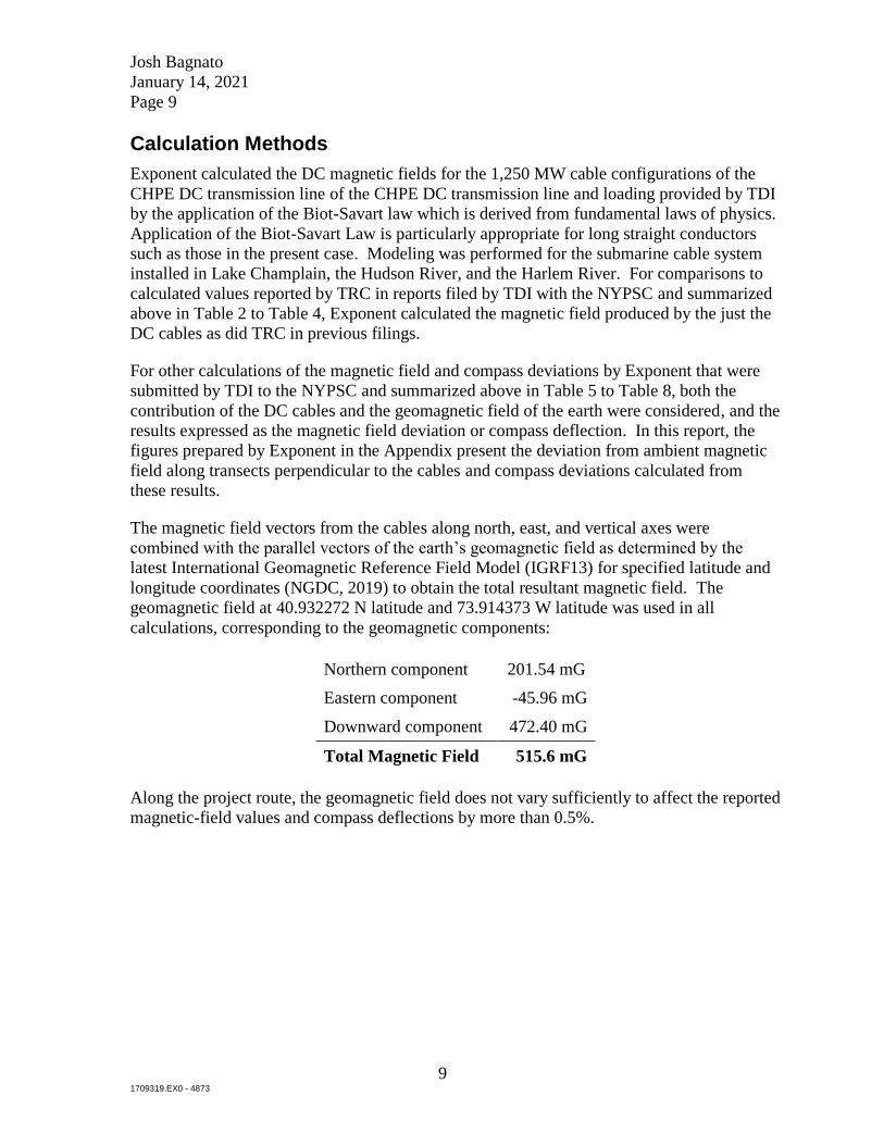


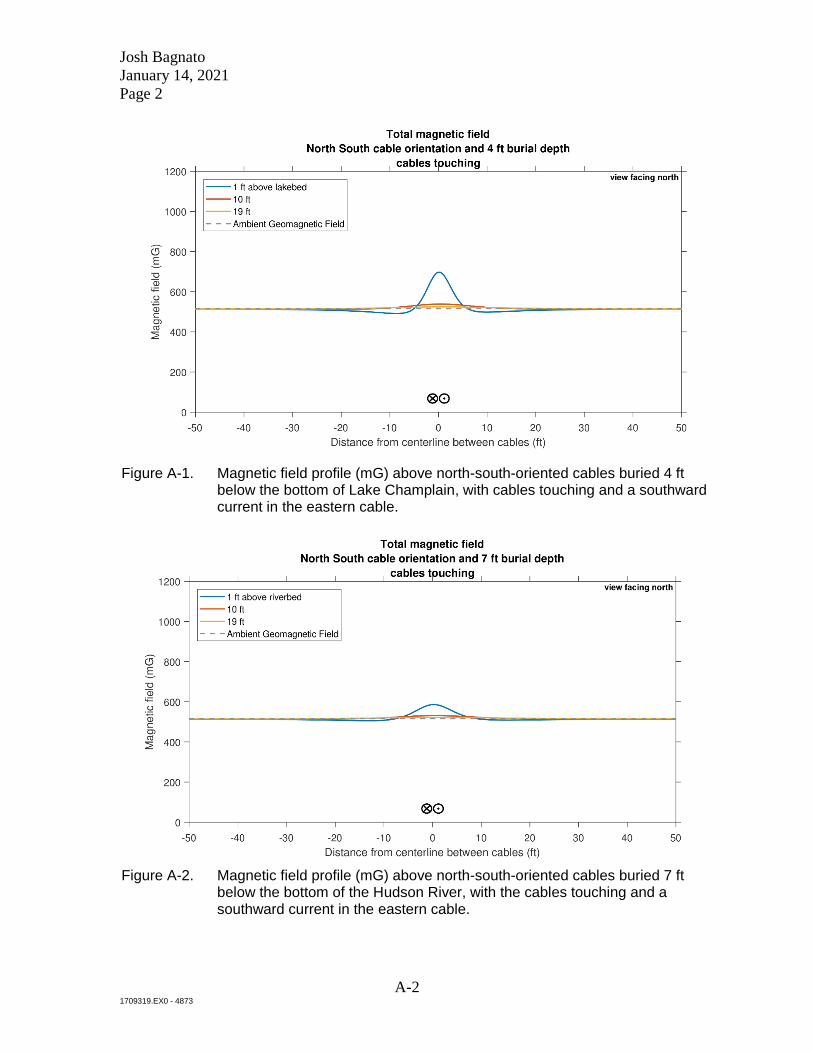


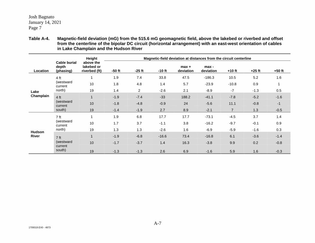


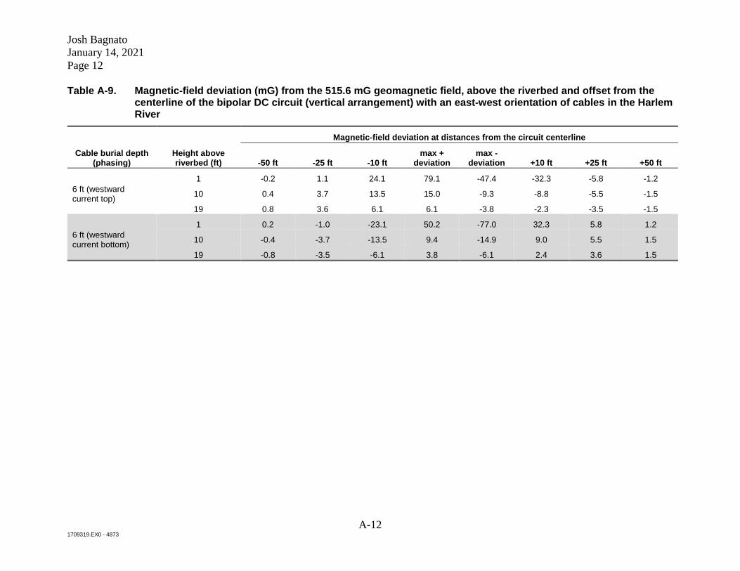


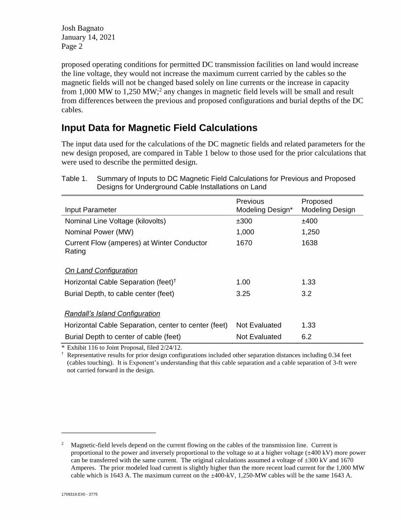


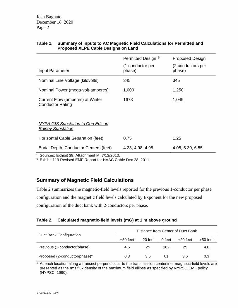


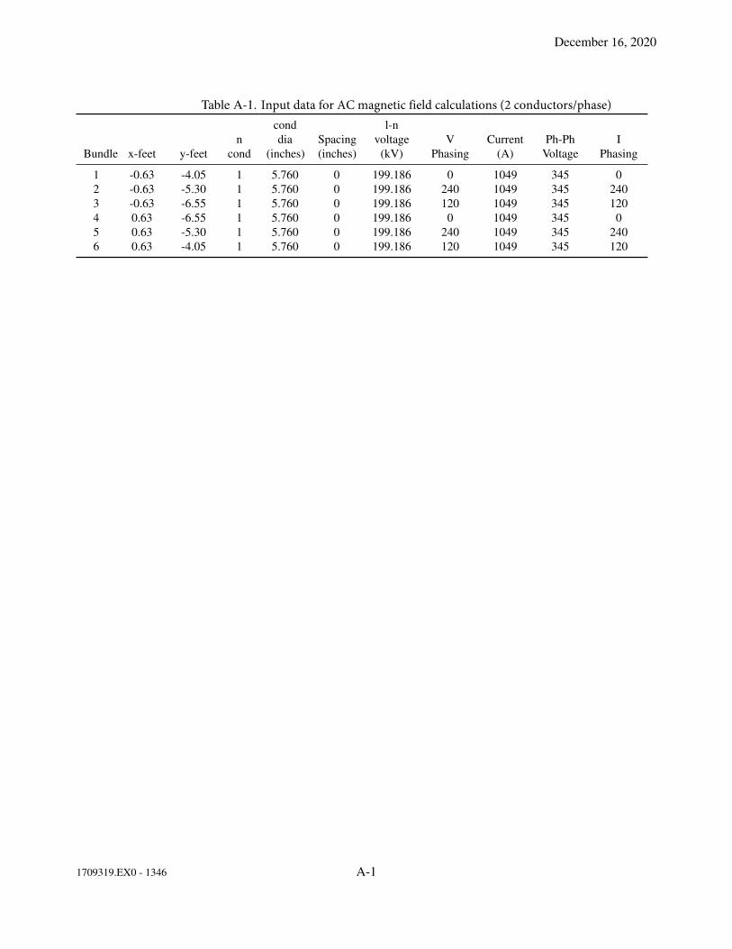


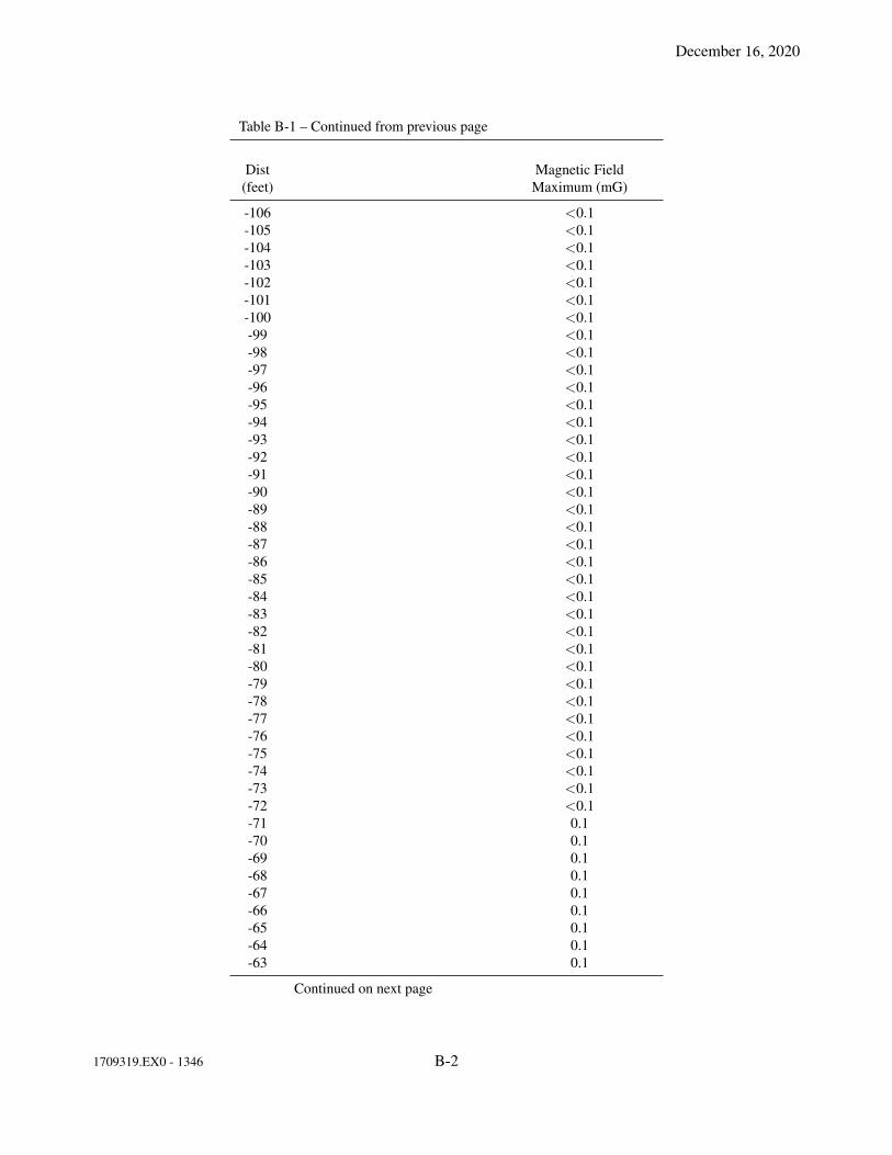


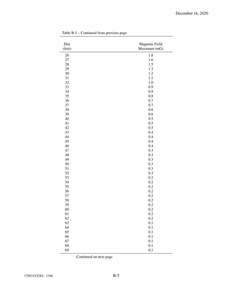


![[Shinobi] Bleach 481](https://static.documents.pub/doc/80x56/568c36c51a28ab0235994a49/shinobi-bleach-481.jpg)


