HAL Id: hal-01785224 https://hal.archives-ouvertes.fr/hal-01785224 Submitted on 4 Jun 2018 HAL is a multi-disciplinary open access archive for the deposit and dissemination of sci- entific research documents, whether they are pub- lished or not. The documents may come from teaching and research institutions in France or abroad, or from public or private research centers. L’archive ouverte pluridisciplinaire HAL, est destinée au dépôt et à la diffusion de documents scientifiques de niveau recherche, publiés ou non, émanant des établissements d’enseignement et de recherche français ou étrangers, des laboratoires publics ou privés. Reactive Power Compensation Improvement Technique for Injection Substations in Nigeria D Idoniboyeobu, B Wokoma, S Evoh To cite this version: D Idoniboyeobu, B Wokoma, S Evoh. Reactive Power Compensation Improvement Technique for Injection Substations in Nigeria. International Journal of Scientific & Engineering Research, Ravi Mittal, 2018, 9 (4), pp.1183-1190. hal-01785224
Transcript
HAL Id: hal-01785224https://hal.archives-ouvertes.fr/hal-01785224
Submitted on 4 Jun 2018
HAL is a multi-disciplinary open accessarchive for the deposit and dissemination of sci-entific research documents, whether they are pub-lished or not. The documents may come fromteaching and research institutions in France orabroad, or from public or private research centers.
L’archive ouverte pluridisciplinaire HAL, estdestinée au dépôt et à la diffusion de documentsscientifiques de niveau recherche, publiés ou non,émanant des établissements d’enseignement et derecherche français ou étrangers, des laboratoirespublics ou privés.
Reactive Power Compensation Improvement Techniquefor Injection Substations in Nigeria
D Idoniboyeobu, B Wokoma, S Evoh
To cite this version:D Idoniboyeobu, B Wokoma, S Evoh. Reactive Power Compensation Improvement Technique forInjection Substations in Nigeria. International Journal of Scientific & Engineering Research, RaviMittal, 2018, 9 (4), pp.1183-1190. �hal-01785224�
Reactive Power Compensation Improvement Technique for Injection Substations in Nigeria
D. C. Idoniboyeobu, B. A. Wokoma, S. Evoh
Abstract: The contemporary power system is intricate in structure, it comprises of enormous number of distinct static and dynamic devices. The ever increasing demand for electrical power by consumers on the existing AC transmission power system via injection station due to urbanization poses challenges of voltage thicker, voltage instability, overloaded lines and congestion of lines thus exceeding their thermal limits which result to malfunction and eventually breakdown of transformers due to stress. In this research work, the shunt compensation method is adopted to compensate reactive power, electrical buses and fitter in conjunction with a family of flexible alternating current transmission systems (FACTS) is used to design a system to counter the challenge at the injection station, MATLAB is used to verified the functionality and effeteness of the designed on AC transmission network. Three cases were considered, during fault current, capacitive load and inductive load. The analysis demonstrates a significant improvement on the reactive power of the AC transmission network. This illustrate that the improved technique (STATCOM plus) provides an interpretation to the challenges of malfunction and breakdown of the distribution transformer at the injection station, this is to say that with the integration of the STARTCOM plus on the AC transmission power system reactive power is compensated thus increase in system capacity is achieved, allowing suppliers to have excess of power for marketing and reduction of electricity bills for consumers.
Index Terms— Power distribution network, Power loss reduction, Voltage regulation, Reactive power compensation, Capacitive load, Inductive load, STATCOM plus.
—————————— ——————————
1 INTRODUCTION n Nigeria, the transmission system forms the pillar of the integrated power systems and operate at the highest voltage level which is within the range of 330KV to 132KV. The
voltages generated at the generating stations are usually be-tween 11KV to 23KV which are stepped up to the transmission voltage via sophisticated power transformer and transmitted to transmission sub-stations where the voltages are utilized at stepped down range to sub-transmission level of voltage (132KV-33KV-11KV) depending on the desired level of volt-age.
In a third world country like Nigeria, that has seen an ex-ponential increase in population growth on the last decade, there is a serious inequality between consumers’ need for power consumption and the inability of generating sources to meet the growing demand. Rivers State in Nigeria is no excep-tion to this rule. Due to oil boom people of various ranks and class are relocating to Port Harcourt; the Rivers State capital to better their livelihood. In the last few years, Rivers State Gov-ernment had intensified effort towards the installation of new power plants and associated network of conductors and other related equipment, wherefore meeting the growing request of the general populace. However, it is regrettable to state that, all these efforts have not been met with much success due the following; the transmission system is faced with the challenge of voltage regulation from the national grid; line losses on the transmission lines etc. It is quite obvious that the basic re-quirement for a smooth conveyance of energy is the equilib-rium amid supply and demand of power.
It is obvious that in order for the oil rich Rivers State Gov-
ernment of Nigeria to improve on power supply to its timing populace, lots of effort are required to improve on the trans-mission line capacity; which is largely dependent on both ac-
tive and reactive power flow. Hence the call for improved re-active power compensation [1] of the functional power sys-tem. More effort must be made to manage and improve reac-tive power which plays a significant role towards the achievement of required or acceptable power efficiency. Poorly managed reactive power flow in power systems result in poor voltage regulation, increased power losses and some-times long duration of power system outage, which altimately leads to consumer dis-satisfaction. Knowing that reactive power is proportional to the supply voltage thus it is required to improve the system bus voltages [2].
The greater the reactive power moving through a system,
the lesser the capacity of the line. In other words, reactive power is proportional to voltage drop. Thus it logically fol-lows that, the greater the reactive power flow through the transmission lines, the greater the voltage drop resulting in lower bus voltage [3]. This means that the low voltages at dis-tribution system buses will lead to low voltage supply to con-sumers which is objectionable. Furthermore, reactive power can be likened to a high-way on which active power flows. That is to say, that proper reactive power in the system leads to proper real power flow in the system [4].
It is in this regard this paper seek to highlight and recom-
mend the application of an improved technique on reactive power compensation for the 7.5MVA injection station located at A. K. Horsfall Street in Port Harcourt, to help improve power consumption and power quality for consumers within the environs.
2 RELATED WORKS Many researchers have investigated the improvent on reactive
power compensation on transmission lines as well as distribu-tion networks for different voltage levels [4], [5] and [6]. In some of these researches, the reactive power compensation improvements were achieved through placement of capacitors and the use of FACT devices such as SSSC, UPFC, SVC, D-STATCOM, STATCOM, STATCOM Plus etc. Different control strategies such as Synchronous Reference Frame theory (SRF), Instantaneous Power theory (IRP), Symmetrical Component theory (SC), and the Modified p-q theory etc. are also pro-posed in controlling the mentioned FACT devices [7], [8], [9], [10] and [11].
Comparative studies of the models, applications and bene-fits of the uses of these FACT devices for reactive power com-pensation are presented in [12], [13], [14] and [15]. Artificial Intelligent (AI) and Evolutionary Algorithms are extensively being use in the optimization of the sizing of reactive compen-sators and the optimal location techniques of placement of capacitors and FACTs devices on distribution networks to improve reactive power management [16], [17], [18], [19], [20] and [21].
3 METHODOLOGY For the purpose of these work the Static Synchronous
Compensator (STATCOM) under the Shunt Compensation Technique was improved by integrating the band pass filter and the Static Synchronous Compensator in to the AC trans-mission power system of the 7.5MVA injection substation for more efficient and effective reactive power compensation. Simulations were done using MATLAB 2016 power system tool for proper analysis.
STATCOM plus is very much analogous to a synchronous
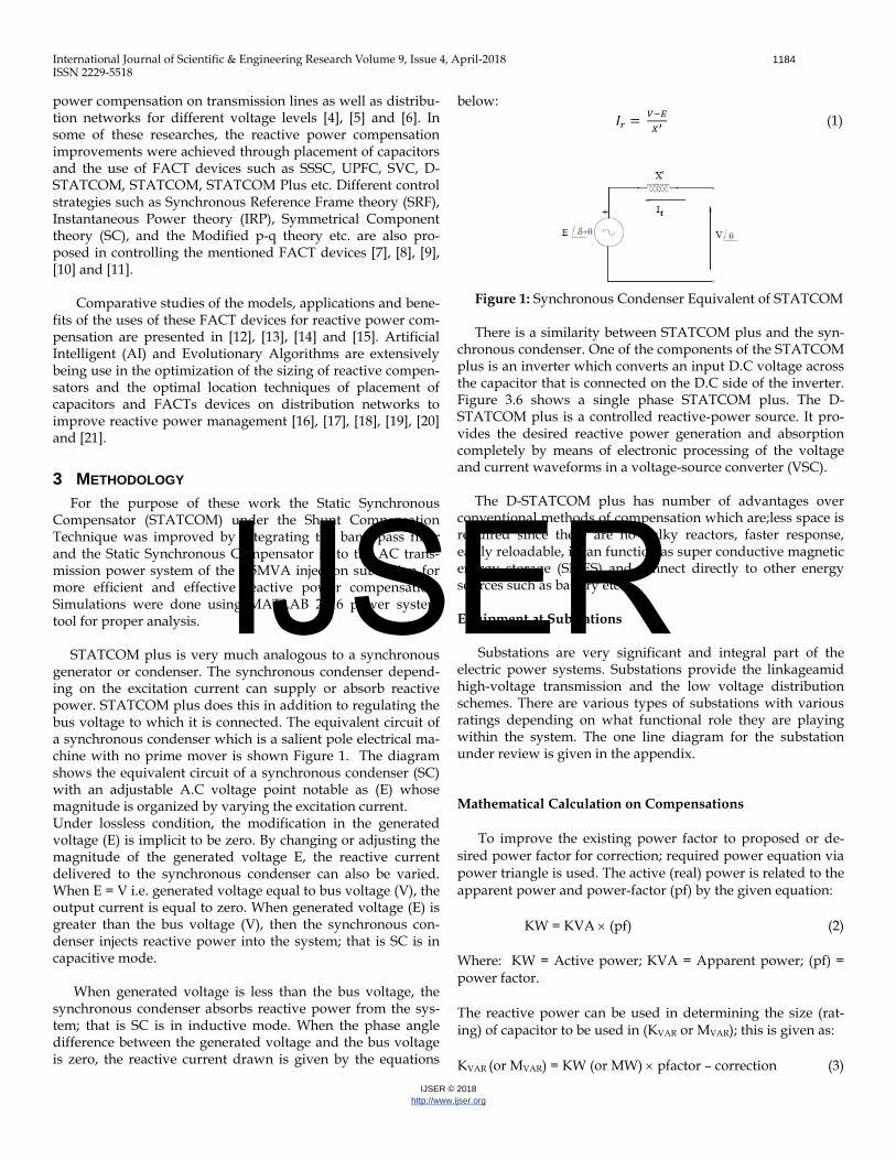
generator or condenser. The synchronous condenser depend-ing on the excitation current can supply or absorb reactive power. STATCOM plus does this in addition to regulating the bus voltage to which it is connected. The equivalent circuit of a synchronous condenser which is a salient pole electrical ma-chine with no prime mover is shown Figure 1. The diagram shows the equivalent circuit of a synchronous condenser (SC) with an adjustable A.C voltage point notable as (E) whose magnitude is organized by varying the excitation current. Under lossless condition, the modification in the generated voltage (E) is implicit to be zero. By changing or adjusting the magnitude of the generated voltage E, the reactive current delivered to the synchronous condenser can also be varied. When E = V i.e. generated voltage equal to bus voltage (V), the output current is equal to zero. When generated voltage (E) is greater than the bus voltage (V), then the synchronous con-denser injects reactive power into the system; that is SC is in capacitive mode.
When generated voltage is less than the bus voltage, the synchronous condenser absorbs reactive power from the sys-tem; that is SC is in inductive mode. When the phase angle difference between the generated voltage and the bus voltage is zero, the reactive current drawn is given by the equations
below: 𝐼𝑟 = 𝑉−𝐸
𝑋′ (1)
Figure 1: Synchronous Condenser Equivalent of STATCOM There is a similarity between STATCOM plus and the syn-
chronous condenser. One of the components of the STATCOM plus is an inverter which converts an input D.C voltage across the capacitor that is connected on the D.C side of the inverter. Figure 3.6 shows a single phase STATCOM plus. The D-STATCOM plus is a controlled reactive-power source. It pro-vides the desired reactive power generation and absorption completely by means of electronic processing of the voltage and current waveforms in a voltage-source converter (VSC).
The D-STATCOM plus has number of advantages over conventional methods of compensation which are;less space is required since there are no bulky reactors, faster response, easily reloadable, it can function as super conductive magnetic energy storage (SMES) and connect directly to other energy sources such as battery etc. Equipment at Substations
Substations are very significant and integral part of the electric power systems. Substations provide the linkageamid high-voltage transmission and the low voltage distribution schemes. There are various types of substations with various ratings depending on what functional role they are playing within the system. The one line diagram for the substation under review is given in the appendix.
Mathematical Calculation on Compensations
To improve the existing power factor to proposed or de-sired power factor for correction; required power equation via power triangle is used. The active (real) power is related to the apparent power and power-factor (pf) by the given equation:
KW = KVA × (pf) (2)
Where: KW = Active power; KVA = Apparent power; (pf) = power factor.
The reactive power can be used in determining the size (rat-ing) of capacitor to be used in (KVAR or MVAR); this is given as:
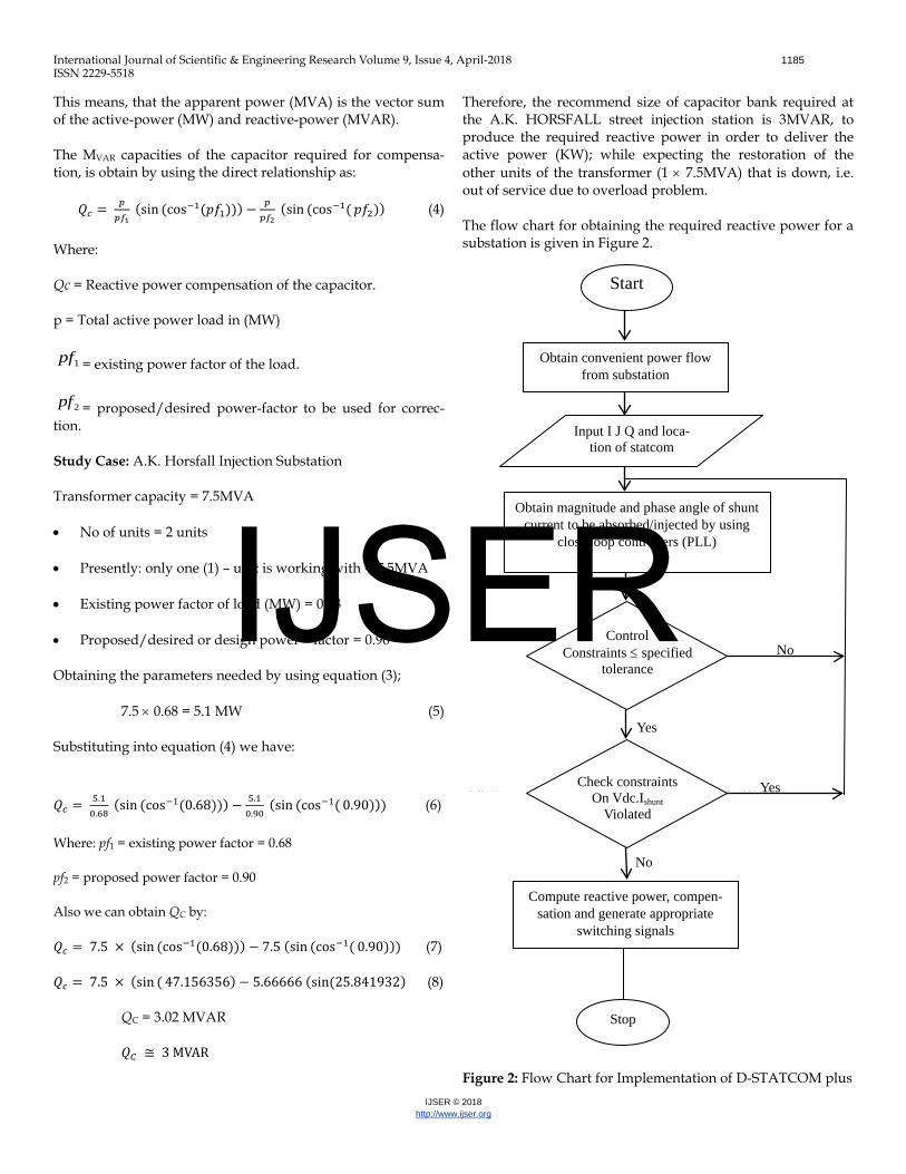
Therefore, the recommend size of capacitor bank required at the A.K. HORSFALL street injection station is 3MVAR, to produce the required reactive power in order to deliver the active power (KW); while expecting the restoration of the other units of the transformer (1 × 7.5MVA) that is down, i.e. out of service due to overload problem.
The flow chart for obtaining the required reactive power for a substation is given in Figure 2.
Figure 2: Flow Chart for Implementation of D-STATCOM plus
Start
Obtain convenient power flow from substation
Obtain magnitude and phase angle of shunt current to be absorbed/injected by using
close loop controllers (PLL)
Compute reactive power, compen-sation and generate appropriate
4 RESULTS AND DISCUSSION The Distribution STATCOM plus (D- STARTCOM plus)
dynamic response was observed for various system voltages with respect to reference set voltages. The simulations circuit has an equivalent circuit of the D-STATCOM plus connected to a domestic distribution network system which precisely loads at the Rivers State Government House. The system modelled in MATLAB has the following simulation input pa-rameters as listed in Table 1.
Table 1
Simulation Parameters
Number Values System 01 IGBT built, 3 arms,
6 pulse, carrier fre-quency = 1080Hz, sample period = 5us
03 Proportional gain Kp = 0.5 integral gain Ki = 500, sample time = 50us
Proportional in-tegral (pi) con-troller
04 R =25.1ohms, L = 400e-3H
Load
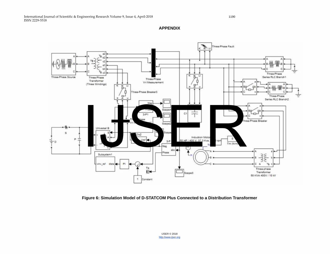
As shown in the figure at the appendix, the test system is
injecting 11kV, 50Hz signal, represented by a thevenin equiva-lent, feeding distribution lines through a (3) three-winding transformer connected in Yg/Yg/Yg, 33/11/11kV matrix. A varying load is connected to the 11kV, secondary side of the transformer. A two-level D-STATCOM plus is connected to the 11kV tertiary winding to provide instantaneous voltage support at the load point.
The system performance is analysed for compensating reactive power on different system conditions so as to achieve rated voltage at a given load, these various cases are discussed and result as follows: Case I: System Voltage Profile during a Fault Current A three-phase short-circuit-ground fault is applied at the load point of the simulation model through a fault resistance of 0.66 Ω, the transition period for the defect is considered from 0.3
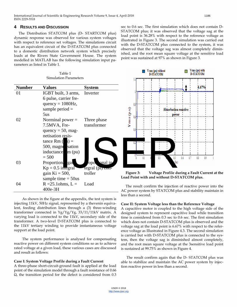
sec to 0.6 sec. The first simulation which does not contain D-STATCOM plus; it was observed that the voltage sag at the load point is 36.28% with respect to the reference voltage as illustrated in Figure 3. The second simulation was carried out with the D-STATCOM plus connected to the system, it was observed that the voltage sag was almost completely dimin-ished, and the root mean square voltage at the sensitive load point was sustained at 97% as shown in Figure 3.
Figure 3: Voltage Profile during a Fault Current at the
Load Point with and without D-STATCOM plus. The result confirm the injection of reactive power into the
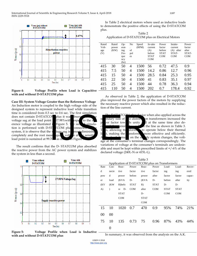
AC power system by STATCOM plus and stability maintain in less than a second. Case II: System Voltage less than the Reference Voltage A capacitive motor is coupled to the high voltage side of the designed system to represent capacitive load while transition time is considered from 0.3 sec to 0.6 sec. The first simulation which does not contain D-STATCOM plus is observed and the voltage sag at the load point is 6.67% with respect to the refer-ence voltage as Illustrated in Figure 4.3. The second simulation is carried but with D-STATCOM plus is connected to the sys-tem, then the voltage sag is diminished almost completely, and the root mean square voltage at the 3sensitive load point is sustained at 99.75% as shown in Figure 4.
The result confirm again that the D- STATCOM plus was able to stabilize and maintain the AC power system by injec-tion reactive power in less than a second.
Figure 4: Voltage Profile when Load is Capacitive with and without D-STATCOM plus
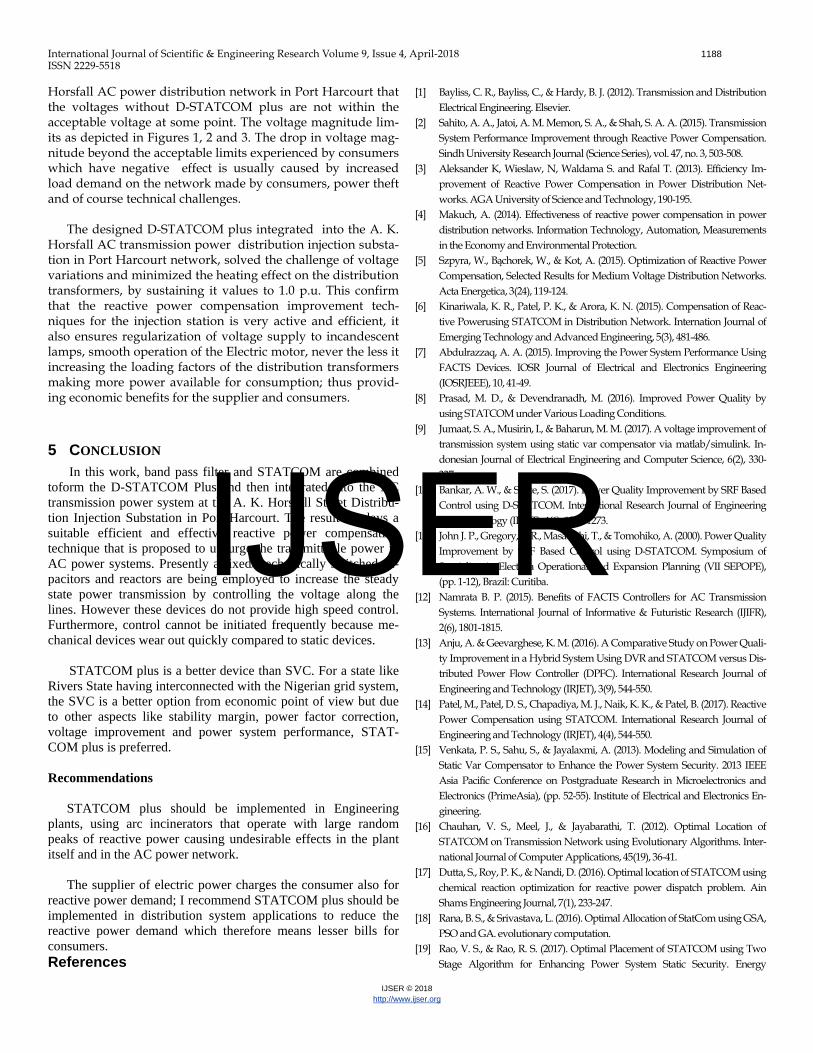
Case III: System Voltage Greater than the Reference Voltage An Induction motor is coupled to the high voltage side of the designed system to represent inductive load while transition time is considered from 0.3 sec to 0.6 sec. The first simulation does not contain D-STATCOM plus it was observed that the voltage sag at the load point is 17.98%with respect to the ref-erence voltage as illustrated in Figure 5. The second simula-tion is performed with D-STATCOM plus connected to the system, it is observe that the voltage sag is almost diminished completely and the root mean square voltage at the sensitive load point is sustained at 99.70% as shown in Figure 5.
The result confirms that the D- STATCOM plus absorbed the reactive power from the AC power system and stabilizes the system in less than a second. Figure 5: Voltage Profile when Load is Inductive with and without D-STATCOM plus
In Table 2 electrical motors where used as inductive loads to demonstrate the positive effects of using the D-STATCOM plus.
Table 2 Application of D-STATCOM plus on Electrical Motors
As observed in Table 2, the application of D-STATCOM
plus improved the power factors of the motors by supplying the necessary reactive power which also resulted in the reduc-tion of the line current.
The D-STATCOM plus device when also applied across the secondary side of two distribution transformers increased the power factor towards unity and at the same time also de-creased the current drawn from the line as shown in Table 3. Thus, allowing transformers to operate below their thermal limit, making the transformer more effective and efficiently. As the load demand on the supply system changes, the volt-age at the consumer’s terminal changes correspondingly. The variations of voltage at the consumer’s terminals are undesir-able and must be kept within prescribed limits of +/-6% of the declared voltage (240L-N or 415L-L).
Table 3
Application of D-STATCOM plus on Transformers Rate
d
pow
er
(KV
A)
Con-
necte
d
load
(KW
)
Reac-
tive
power
(KVA
R)befo
re D-
STAT
COM
Power
factor
before
D-
STAT
COM
Reac-
tive
power
(KVA
R)
after
D-
STAT
COM
Power
factor
after
D-
STAT
COM
Load-
ing
factor
before
D-
STAT
COM
Load-
ing
factor
after
D-
STAT
COM
Recov-
ered
capac-
ity
15
00
10
00
1020 0.7 470 0.9 95% 74% 21%
75 10
0
135 0.73 75 0.96 87% 43% 44%
In summary, it was observed from the analysis on the A.K.
Horsfall AC power distribution network in Port Harcourt that the voltages without D-STATCOM plus are not within the acceptable voltage at some point. The voltage magnitude lim-its as depicted in Figures 1, 2 and 3. The drop in voltage mag-nitude beyond the acceptable limits experienced by consumers which have negative effect is usually caused by increased load demand on the network made by consumers, power theft and of course technical challenges.
The designed D-STATCOM plus integrated into the A. K. Horsfall AC transmission power distribution injection substa-tion in Port Harcourt network, solved the challenge of voltage variations and minimized the heating effect on the distribution transformers, by sustaining it values to 1.0 p.u. This confirm that the reactive power compensation improvement tech-niques for the injection station is very active and efficient, it also ensures regularization of voltage supply to incandescent lamps, smooth operation of the Electric motor, never the less it increasing the loading factors of the distribution transformers making more power available for consumption; thus provid-ing economic benefits for the supplier and consumers.
5 CONCLUSION In this work, band pass filter and STATCOM are combined
toform the D-STATCOM Plus and then integrated into the AC transmission power system at the A. K. Horsfall Street Distribu-tion Injection Substation in Port Harcourt. The result displays a suitable efficient and effective reactive power compensation technique that is proposed to upsurge the transmittable power in AC power systems. Presently a fixed/mechanically switched ca-pacitors and reactors are being employed to increase the steady state power transmission by controlling the voltage along the lines. However these devices do not provide high speed control. Furthermore, control cannot be initiated frequently because me-chanical devices wear out quickly compared to static devices.
STATCOM plus is a better device than SVC. For a state like Rivers State having interconnected with the Nigerian grid system, the SVC is a better option from economic point of view but due to other aspects like stability margin, power factor correction, voltage improvement and power system performance, STAT-COM plus is preferred. Recommendations
STATCOM plus should be implemented in Engineering plants, using arc incinerators that operate with large random peaks of reactive power causing undesirable effects in the plant itself and in the AC power network.
The supplier of electric power charges the consumer also for reactive power demand; I recommend STATCOM plus should be implemented in distribution system applications to reduce the reactive power demand which therefore means lesser bills for consumers. References
[1] Bayliss, C. R., Bayliss, C., & Hardy, B. J. (2012). Transmission and Distribution Electrical Engineering. Elsevier.
[2] Sahito, A. A., Jatoi, A. M. Memon, S. A., & Shah, S. A. A. (2015). Transmission System Performance Improvement through Reactive Power Compensation. Sindh University Research Journal (Science Series), vol. 47, no. 3, 503-508.
[3] Aleksander K, Wieslaw, N, Waldama S. and Rafal T. (2013). Efficiency Im-provement of Reactive Power Compensation in Power Distribution Net-works. AGA University of Science and Technology, 190-195.
[4] Makuch, A. (2014). Effectiveness of reactive power compensation in power distribution networks. Information Technology, Automation, Measurements in the Economy and Environmental Protection.
[5] Szpyra, W., Bąchorek, W., & Kot, A. (2015). Optimization of Reactive Power Compensation, Selected Results for Medium Voltage Distribution Networks. Acta Energetica, 3(24), 119-124.
[6] Kinariwala, K. R., Patel, P. K., & Arora, K. N. (2015). Compensation of Reac-tive Powerusing STATCOM in Distribution Network. Internation Journal of Emerging Technology and Advanced Engineering, 5(3), 481-486.
[7] Abdulrazzaq, A. A. (2015). Improving the Power System Performance Using FACTS Devices. IOSR Journal of Electrical and Electronics Engineering (IOSRJEEE), 10, 41-49.
[8] Prasad, M. D., & Devendranadh, M. (2016). Improved Power Quality by using STATCOM under Various Loading Conditions.
[9] Jumaat, S. A., Musirin, I., & Baharun, M. M. (2017). A voltage improvement of transmission system using static var compensator via matlab/simulink. In-donesian Journal of Electrical Engineering and Computer Science, 6(2), 330-337.
[10] Bankar, A. W., & Shete, S. (2017). Power Quality Improvement by SRF Based Control using D-STATCOM. International Research Journal of Engineering and Technology (IRJET), 4(6), 1270-1273.
[11] John J. P., Gregory, F. R., Masatoshi, T., & Tomohiko, A. (2000). Power Quality Improvement by SRF Based Control using D-STATCOM. Symposium of Specialists in Electrica Operational and Expansion Planning (VII SEPOPE), (pp. 1-12), Brazil: Curitiba.
[12] Namrata B. P. (2015). Benefits of FACTS Controllers for AC Transmission Systems. International Journal of Informative & Futuristic Research (IJIFR), 2(6), 1801-1815.
[13] Anju, A. & Geevarghese, K. M. (2016). A Comparative Study on Power Quali-ty Improvement in a Hybrid System Using DVR and STATCOM versus Dis-tributed Power Flow Controller (DPFC). International Research Journal of Engineering and Technology (IRJET), 3(9), 544-550.
[14] Patel, M., Patel, D. S., Chapadiya, M. J., Naik, K. K., & Patel, B. (2017). Reactive Power Compensation using STATCOM. International Research Journal of Engineering and Technology (IRJET), 4(4), 544-550.
[15] Venkata, P. S., Sahu, S., & Jayalaxmi, A. (2013). Modeling and Simulation of Static Var Compensator to Enhance the Power System Security. 2013 IEEE Asia Pacific Conference on Postgraduate Research in Microelectronics and Electronics (PrimeAsia), (pp. 52-55). Institute of Electrical and Electronics En-gineering.
[16] Chauhan, V. S., Meel, J., & Jayabarathi, T. (2012). Optimal Location of STATCOM on Transmission Network using Evolutionary Algorithms. Inter-national Journal of Computer Applications, 45(19), 36-41.
[17] Dutta, S., Roy, P. K., & Nandi, D. (2016). Optimal location of STATCOM using chemical reaction optimization for reactive power dispatch problem. Ain Shams Engineering Journal, 7(1), 233-247.
[18] Rana, B. S., & Srivastava, L. (2016). Optimal Allocation of StatCom using GSA, PSO and GA. evolutionary computation.
[19] Rao, V. S., & Rao, R. S. (2017). Optimal Placement of STATCOM using Two Stage Algorithm for Enhancing Power System Static Security. Energy
Procedia, 117, 575-582. [20] Sahu, N., & Dubey, A. (2015). Optimal Location of Statcom Using Particle
Swarm Optimization in IEEE-14 Bus System to Improve Voltage Profile & THD Reduction. International Journal of Science and Research (IJSR), 4(3), 2595-2601.
[21] Gerbex, S., Cherkaoui, R., & Germond, A. J. (2001). Optimal location of multi-type FACTS devices in a power system by means of genetic algorithms. IEEE transactions on power systems, 16(3), 537-544.