16
d.o.o. d.o.o. ELEKTROTEHNI©KO PODJETJE Leskoπkova cesta 12, 1000 Ljubljana, SLOVENIA
d.o.o.d.o.o.ELEKTROTEHNI©KO PODJETJELeskoπkova cesta 12, 1000 Ljubljana, SLOVENIA
SETTING UP REACTIVE POWER COMPENSATION DEVICES
SELECTING A REACTIVE POWER COMPENSATION DEVICE
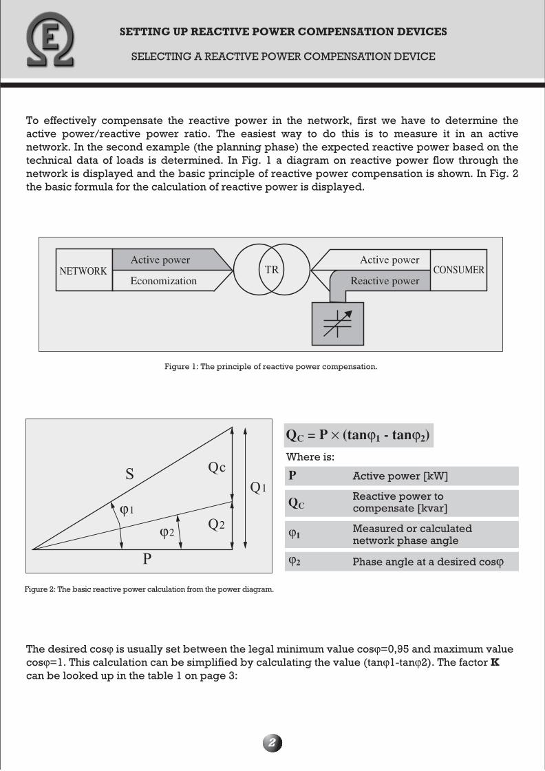
To effectively compensate the reactive power in the network, first we have to determine the active power/reactive power ratio. The easiest way to do this is to measure it in an active network. In the second example (the planning phase) the expected reactive power based on the technical data of loads is determined. In Fig. 1 a diagram on reactive power flow through the network is displayed and the basic principle of reactive power compensation is shown. In Fig. 2 the basic formula for the calculation of reactive power is displayed.
2
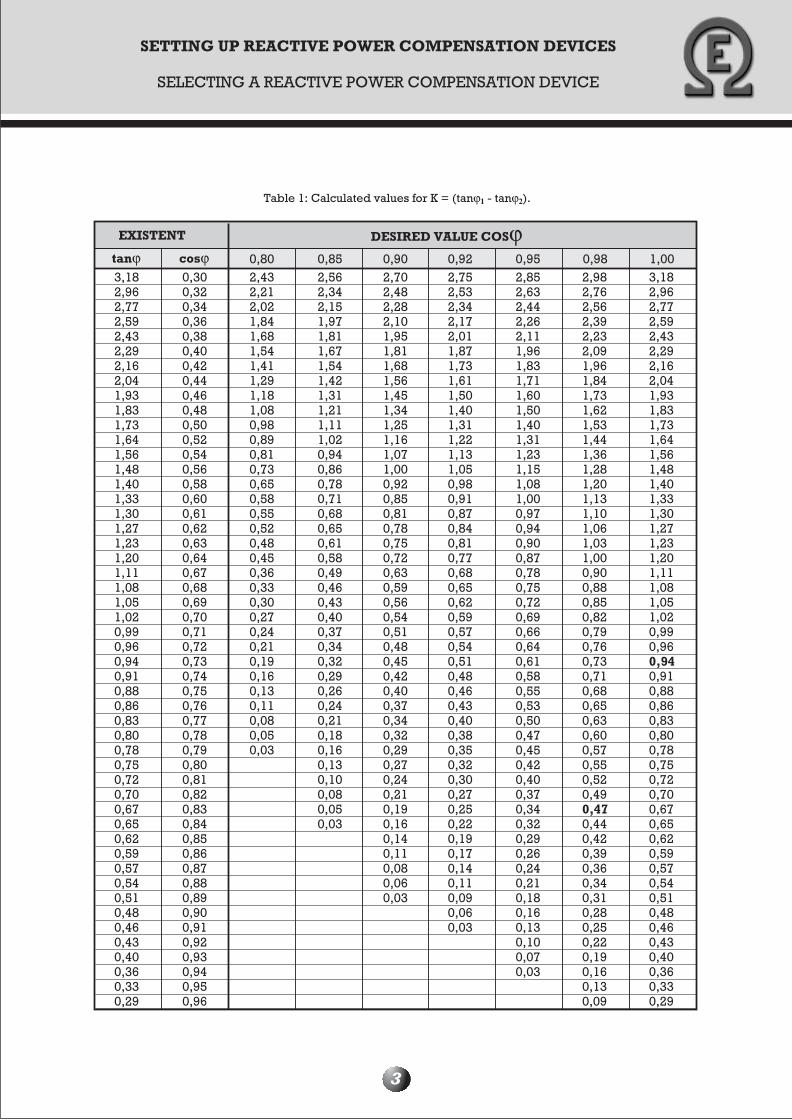
The desired cosϕ is usually set between the legal minimum value cosϕ=0,95 and maximum value cosϕ=1. This calculation can be simplified by calculating the value (tanϕ1-tanϕ2). The factor K can be looked up in the table 1 on page 3:
Figure 2: The basic reactive power calculation from the power diagram.
QC = P × (tanϕ1 - tanϕ2)Where is:
Active power [kW]P
QCReactive power tocompensate [kvar]
ϕ1Measured or calculatednetwork phase angle
ϕ2 Phase angle at a desired cosϕ
Figure 1: The principle of reactive power compensation.
NETWORKActive power Active power
CONSUMEREconomization Reactive power
SETTING UP REACTIVE POWER COMPENSATION DEVICES
SELECTING A REACTIVE POWER COMPENSATION DEVICE
3
Table 1: Calculated values for K = (tanϕ1 - tanϕ2).
3,182,962,772,592,432,29 2,16 2,04 1,93 1,83 1,73 1,64 1,56 1,48 1,40 1,33 1,30 1,27 1,23 1,20 1,11 1,08 1,05 1,02 0,99 0,96 0,94 0,91 0,88 0,86 0,83 0,80 0,78 0,75 0,72 0,70 0,67 0,65 0,62 0,59 0,57 0,54 0,51 0,48 0,46 0,43 0,40 0,36 0,33 0,29
0,30 0,32 0,34 0,36 0,38 0,40 0,42 0,44 0,46 0,48 0,50 0,52 0,54 0,56 0,58 0,60 0,61 0,62 0,63 0,64 0,67 0,68 0,69 0,70 0,71 0,72 0,73 0,74 0,75 0,76 0,77 0,78 0,79 0,80 0,81 0,82 0,83 0,84 0,85 0,86 0,87 0,88 0,89 0,90 0,91 0,92 0,93 0,94 0,95 0,96
2,43 2,21 2,02 1,84 1,68 1,54 1,41 1,29 1,18 1,08 0,98 0,89 0,81 0,73 0,65 0,58 0,55 0,52 0,48 0,45 0,36 0,33 0,30 0,27 0,24 0,21 0,19 0,16 0,13 0,11 0,08 0,05 0,03
2,56 2,34 2,15 1,97 1,81 1,67 1,54 1,42 1,31 1,21 1,11 1,02 0,94 0,86 0,78 0,71 0,68 0,65 0,61 0,58 0,49 0,46 0,43 0,40 0,37 0,34 0,32 0,29 0,26 0,24 0,21 0,18 0,16 0,13 0,10 0,08 0,05 0,03
2,70 2,48 2,28 2,10 1,95 1,81 1,68 1,56 1,45 1,34 1,25 1,16 1,07 1,00 0,92 0,85 0,81 0,78 0,75 0,72 0,63 0,59 0,56 0,54 0,51 0,48 0,45 0,42 0,40 0,37 0,34 0,32 0,29 0,27 0,24 0,21 0,19 0,16 0,14 0,11 0,08 0,06 0,03
2,75 2,53 2,34 2,17 2,01 1,87 1,73 1,61 1,50 1,40 1,31 1,22 1,13 1,05 0,98 0,91 0,87 0,84 0,81 0,77 0,68 0,65 0,62 0,59 0,57 0,54 0,51 0,48 0,46 0,43 0,40 0,38 0,35 0,32 0,30 0,27 0,25 0,22 0,19 0,17 0,14 0,11 0,09 0,06 0,03
2,85 2,63 2,44 2,26 2,11 1,96 1,83 1,71 1,60 1,501,40 1,31 1,23 1,15 1,08 1,00 0,97 0,94 0,90 0,87 0,78 0,75 0,72 0,69 0,66 0,64 0,61 0,58 0,55 0,53 0,50 0,47 0,45 0,42 0,40 0,37 0,34 0,32 0,29 0,26 0,24 0,21 0,18 0,16 0,13 0,10 0,07 0,03
2,98 2,76 2,56 2,39 2,23 2,09 1,96 1,84 1,73 1,62 1,53 1,44 1,36 1,28 1,20 1,13 1,10 1,06 1,03 1,00 0,90 0,88 0,85 0,82 0,79 0,76 0,73 0,71 0,68 0,65 0,63 0,60 0,57 0,55 0,52 0,49 0,47 0,44 0,42 0,39 0,36 0,34 0,31 0,28 0,25 0,22 0,19 0,16 0,13 0,09
3,18 2,96 2,77 2,59 2,43 2,29 2,16 2,04 1,93 1,83 1,73 1,64 1,56 1,48 1,40 1,33 1,30 1,27 1,23 1,20 1,11 1,08 1,05 1,02 0,99 0,96 0,94 0,910,88 0,86 0,83 0,80 0,78 0,75 0,72 0,70 0,67 0,65 0,62 0,59 0,57 0,54 0,51 0,48 0,46 0,43 0,40 0,36 0,33 0,29
EXISTENT DESIRED VALUE COSϕtanϕ cosϕ 0,80 0,85 0,90 0,92 0,95 0,98 1,00
4
SETTING UP REACTIVE POWER COMPENSATION DEVICES
SELECTING A REACTIVE POWER COMPENSATION DEVICE
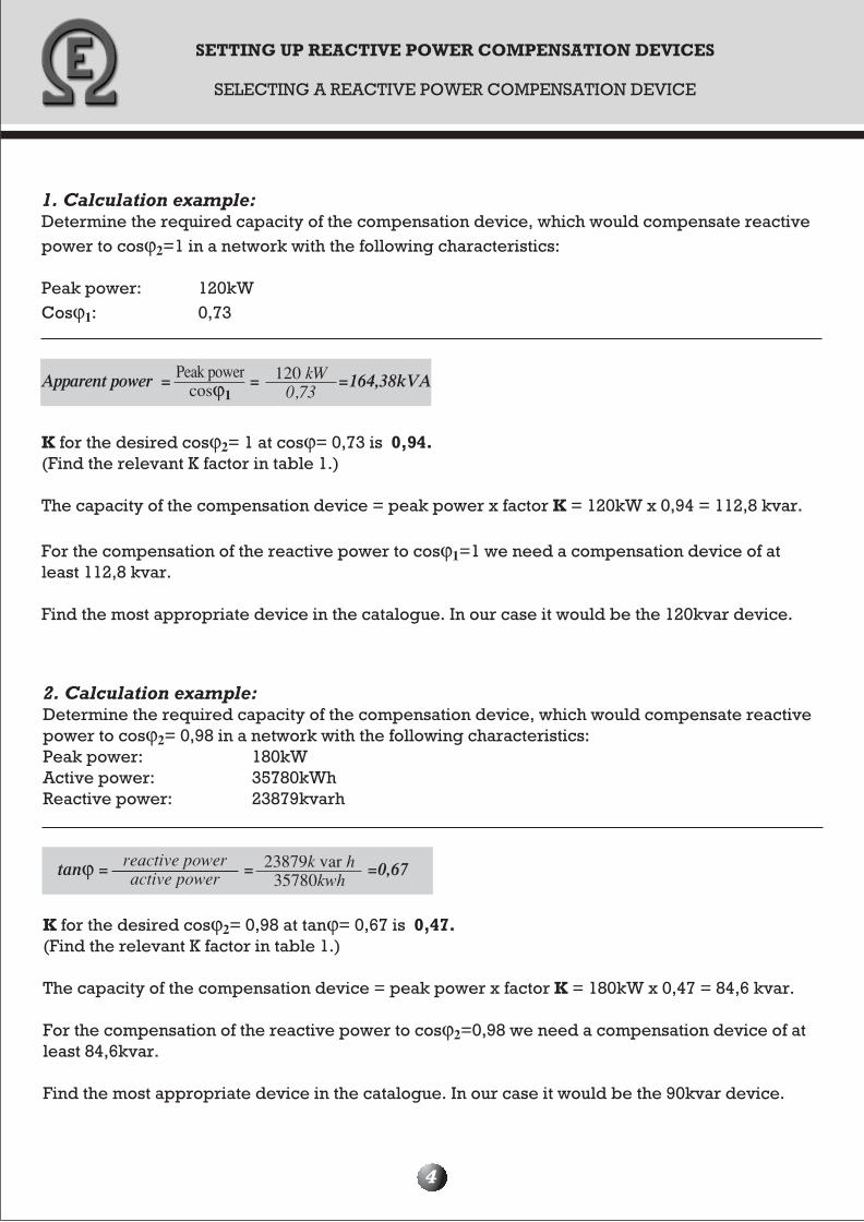
1. Calculation example:Determine the required capacity of the compensation device, which would compensate reactive power to cosϕ2=1 in a network with the following characteristics:
Peak power: 120kWCosϕ1: 0,73
K for the desired cosϕ2= 1 at cosϕ= 0,73 is 0,94. (Find the relevant K factor in table 1.)
The capacity of the compensation device = peak power x factor K = 120kW x 0,94 = 112,8 kvar.
For the compensation of the reactive power to cosϕ1=1 we need a compensation device of at least 112,8 kvar.
Find the most appropriate device in the catalogue. In our case it would be the 120kvar device.
Apparent power = = =164,38kVAPeak powercosϕ1
120 kW0,73
23879k var h35780kwh
tanϕ = = =0,67
2. Calculation example:Determine the required capacity of the compensation device, which would compensate reactive power to cosϕ2= 0,98 in a network with the following characteristics:Peak power: 180kWActive power: 35780kWhReactive power: 23879kvarh
K for the desired cosϕ2= 0,98 at tanϕ= 0,67 is 0,47. (Find the relevant K factor in table 1.)
The capacity of the compensation device = peak power x factor K = 180kW x 0,47 = 84,6 kvar.
For the compensation of the reactive power to cosϕ2=0,98 we need a compensation device of at least 84,6kvar.
Find the most appropriate device in the catalogue. In our case it would be the 90kvar device.
reactive poweractive power
SETTING UP REACTIVE POWER COMPENSATION DEVICES
HIGH HARMONICS IN THE NETWORK AND HARMONIC FILTERS
5
WHERE DO HIGH HARMONICS APPEAR?
High harmonics are generated in a network by non-linear loads, such as: frequency regulators, rectifiers, uninterruptible power sources, fluorescent lamps, welding devices, computers etc.
DISTORTIONS, CAUSED BY HIGH HARMONICS
Non-linear elements in devices e.g. thyristors generate harmonics in the current. As a result, high harmonics in the voltage occur, which cause overloads of capacitor units in compensation devices, ripple control signal interferences and unreliable actuator work in electronic devices, which use the voltage zero crossing. Additionally, they strain mains leads, energy transformers, fuses and switching devices and cause interference in telephone systems. Harmonics are additionally increased by parallel and serial resonances, which can magnify single high harmonics to a multiple value.
WHY DO HIGH HARMONICS REDUCE CAPACITOR LIFE?
High harmonics are to be seen as an increase of the effective value of the current, which runs through the capacitor. This phenomenon causes heating of the capacitor thus reducing its life. Additionally, parallel and serial resonance circuits between capacitors and network inductances can cause a multiple increase of a single high harmonic and with it distortions, which additionally magnify the current that runs through the capacitor. At what frequency the high harmonics resonate depends on the size of capacitors and network characteristics.
REACTIVE POWER COMPENSATION WITH HARMONIC FILTERS
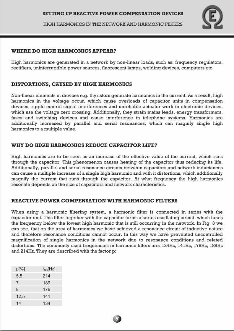
When using a harmonic filtering system, a harmonic filter is connected in series with the capacitor unit. This filter together with the capacitor forms a series oscillating circuit, which tunes the frequency below the lowest high harmonic that is still occurring in the network. In Fig. 3 we can see, that on the area of harmonics we have achieved a resonance circuit of inductive nature and therefore resonance conditions cannot occur. In this way we have prevented uncontrolled magnification of single harmonics in the network due to resonance conditions and related distortions. The commonly used frequencies in harmonic filters are: 134Hz, 141Hz, 176Hz, 189Hz and 214Hz. They are described with the factor p:
SETTING UP REACTIVE POWER COMPENSATION DEVICES
HIGH HARMONICS IN THE NETWORK AND HARMONIC FILTERS
6
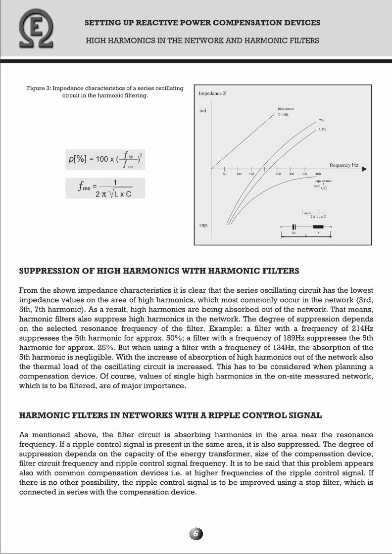
SUPPRESSION OF HIGH HARMONICS WITH HARMONIC FILTERS
From the shown impedance characteristics it is clear that the series oscillating circuit has the lowest impedance values on the area of high harmonics, which most commonly occur in the network (3rd, 5th, 7th harmonic). As a result, high harmonics are being absorbed out of the network. That means, harmonic filters also suppress high harmonics in the network. The degree of suppression depends on the selected resonance frequency of the filter. Example: a filter with a frequency of 214Hz suppresses the 5th harmonic for approx. 50%; a filter with a frequency of 189Hz suppresses the 5th harmonic for approx. 25%. But when using a filter with a frequency of 134Hz, the absorption of the 5th harmonic is negligible. With the increase of absorption of high harmonics out of the network also the thermal load of the oscillating circuit is increased. This has to be considered when planning a compensation device. Of course, values of single high harmonics in the on-site measured network, which is to be filtered, are of major importance.
HARMONIC FILTERS IN NETWORKS WITH A RIPPLE CONTROL SIGNAL
As mentioned above, the filter circuit is absorbing harmonics in the area near the resonance frequency. If a ripple control signal is present in the same area, it is also suppressed. The degree of suppression depends on the capacity of the energy transformer, size of the compensation device, filter circuit frequency and ripple control signal frequency. It is to be said that this problem appears also with common compensation devices i.e. at higher frequencies of the ripple control signal. If there is no other possibility, the ripple control signal is to be improved using a stop filter, which is connected in series with the compensation device.
Figure 3: Impedance characteristics of a series oscillatingcircuit in the harmonic filtering. Impedance Z
inductance
frequency
capacitance
cap.
SETTING UP REACTIVE POWER COMPENSATION DEVICES
HIGH HARMONICS IN THE NETWORK AND HARMONIC FILTERS
7
WHEN SHOULD I USE A HARMONIC FILTER?
Due to the stated facts it is obvious that many factors decide about the type of the selected reactive power compensation device. At first: harmonic filtering yes or no; what should be the filter frequency like; do we have a ripple control signal in the network; which harmonics are mostly expressed in the network; what about the resonance?
When making plans to install compensation devices for a specific situation, all of these factors have to be considered. Besides, the legal regulative and standards e.g. GUIDANCE ON SYSTEMATIC OPERATION OF THE ELECTRICITY DISTRIBUTION SYSTEM (Official gazette of the R of Slovenia: 15/2002) and the standard on quality of electrical power SIST EN 50160, where the limits for single harmonics are defined, have to be taken into consideration.
All of the above questions cannot be answered equally. But we can use the following guidelines:
When looking at a new building and a new transformer station, we do not know, in which conditions the compensation device will operate. Besides, we are not informed about the values of single high harmonics. Still, we can classify the consumers with defining the percentage of non-linear loads in respect to facility load. A harmonic filter is recommended, if more than 15% of the facility load is non-linear! At the same time we have to consider, which of these non-linear loads are connected when electricity consumption is lowest (at week ends), as then resonance conditions may be amplified due to low network suppression as a result of minimally activated loads. When setting the filtering frequency, a compromise between the following factors is needed: suppression of high harmonics in the network, suppression of the ripple control signal and prevention of resonance.
In cases, where the value of high harmonics in the middle-voltage range (10, 20 and 35kV) is known, the following guidelines can be used:
Harmonic filtering is needed, if the 5th harmonic in the voltage exceeds 2% in respect to the fundamental harmonic, or when the overall voltage distortion exceeds 3% in respect to the fundamental harmonic.
It is hard to give a clear answer to the last question as resonance conditions in the network are hardly defined accurately, due to the continuously changing network impedances (e.g. automatic compensation capacitance). Resonance conditions are prevented by using a harmonic filter!
ADVANTAGES OF HARMONIC FILTERS
• reliable reactive power compensation in networks with high harmonics• protecting energy transformers, fuses, switching devices and mains leads• suppression of high harmonics in the voltage• suppression of the effective current value due to suppressed high harmonics• prevention of resonance conditions in the network
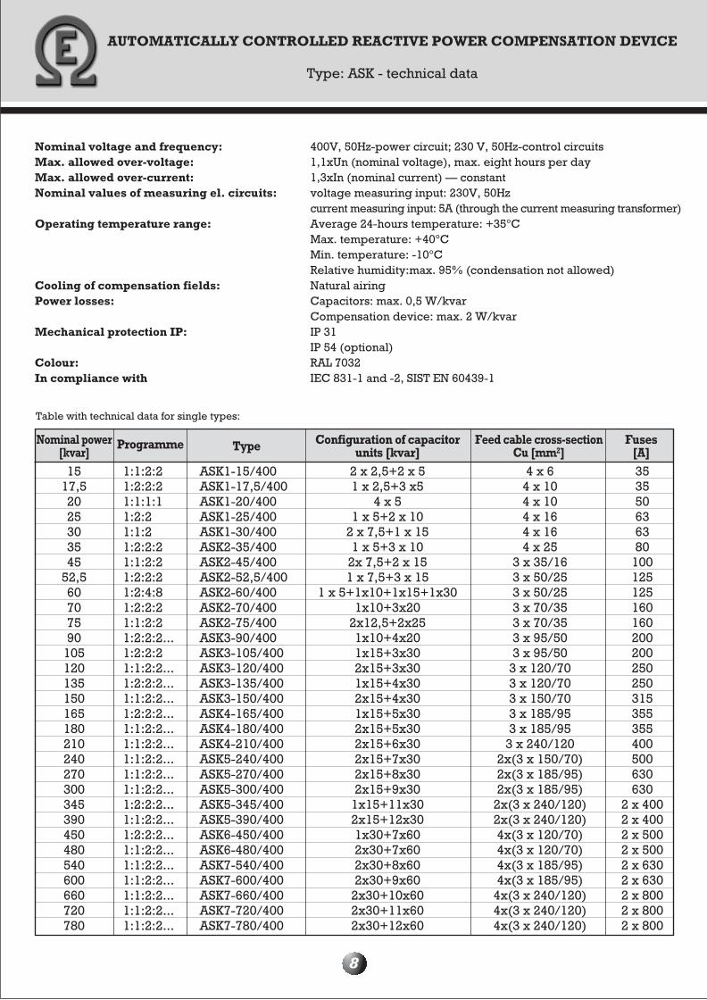
AUTOMATICALLY CONTROLLED REACTIVE POWER COMPENSATION DEVICE
Type: ASK - technical data
8
Table with technical data for single types:
Nominal voltage and frequency: 400V, 50Hz-power circuit; 230 V, 50Hz-control circuits Max. allowed over-voltage: 1,1xUn (nominal voltage), max. eight hours per dayMax. allowed over-current: 1,3xIn (nominal current) — constantNominal values of measuring el. circuits: voltage measuring input: 230V, 50Hz current measuring input: 5A (through the current measuring transformer)Operating temperature range: Average 24-hours temperature: +35°C Max. temperature: +40°C Min. temperature: -10°C Relative humidity:max. 95% (condensation not allowed)Cooling of compensation fields: Natural airingPower losses: Capacitors: max. 0,5 W/kvar Compensation device: max. 2 W/kvarMechanical protection IP: IP 31 IP 54 (optional)Colour: RAL 7032In compliance with IEC 831-1 and -2, SIST EN 60439-1
Nominal power[kvar]
Programme Type Configuration of capacitorunits [kvar]
Feed cable cross-sectionCu [mm2]
Fuses[A]
15 17,5 20 25 30 35 45
52,5 60 70 75 90
105 120 135 150 165 180 210 240 270 300 345 390 450 480 540 600 660 720 780
1:1:2:2 1:2:2:2 1:1:1:1 1:2:2 1:1:2 1:2:2:2 1:1:2:2 1:2:2:2 1:2:4:8 1:2:2:2 1:1:2:2 1:2:2:2...1:2:2:2 1:1:2:2...1:2:2:2...1:1:2:2...1:2:2:2...1:1:2:2...1:1:2:2...1:1:2:2...1:1:2:2...1:1:2:2... 1:2:2:2... 1:1:2:2... 1:2:2:2... 1:1:2:2... 1:1:2:2... 1:1:2:2...1:1:2:2...1:1:2:2...1:1:2:2...
ASK1-15/400 ASK1-17,5/400 ASK1-20/400 ASK1-25/400 ASK1-30/400 ASK2-35/400 ASK2-45/400 ASK2-52,5/400 ASK2-60/400 ASK2-70/400 ASK2-75/400 ASK3-90/400 ASK3-105/400 ASK3-120/400 ASK3-135/400 ASK3-150/400 ASK4-165/400 ASK4-180/400 ASK4-210/400 ASK5-240/400 ASK5-270/400 ASK5-300/400 ASK5-345/400 ASK5-390/400 ASK6-450/400 ASK6-480/400 ASK7-540/400 ASK7-600/400 ASK7-660/400 ASK7-720/400 ASK7-780/400
2 x 2,5+2 x 5 1 x 2,5+3 x5
4 x 5 1 x 5+2 x 10
2 x 7,5+1 x 15 1 x 5+3 x 10
2x 7,5+2 x 15 1 x 7,5+3 x 15
1 x 5+1x10+1x15+1x30 1x10+3x20
2x12,5+2x25 1x10+4x20 1x15+3x30 2x15+3x30 1x15+4x30 2x15+4x30 1x15+5x30 2x15+5x30 2x15+6x30 2x15+7x302x15+8x30 2x15+9x30
1x15+11x30 2x15+12x30 1x30+7x60 2x30+7x60 2x30+8x60 2x30+9x60
2x30+10x60 2x30+11x60 2x30+12x60
4 x 6 4 x 10 4 x 10 4 x 16 4 x 16 4 x 25
3 x 35/16 3 x 50/25 3 x 50/25 3 x 70/35 3 x 70/35 3 x 95/50 3 x 95/50
3 x 120/70 3 x 120/70 3 x 150/70 3 x 185/95 3 x 185/95
3 x 240/120 2x(3 x 150/70)2x(3 x 185/95)2x(3 x 185/95)
2x(3 x 240/120) 2x(3 x 240/120) 4x(3 x 120/70)4x(3 x 120/70) 4x(3 x 185/95) 4x(3 x 185/95)
4x(3 x 240/120) 4x(3 x 240/120) 4x(3 x 240/120)
35 35 50 63 63 80
100 125 125 160 160 200 200 250 250 315 355 355 400 500 630 630
2 x 400 2 x 400 2 x 500 2 x 500 2 x 630 2 x 630 2 x 800 2 x 800 2 x 800
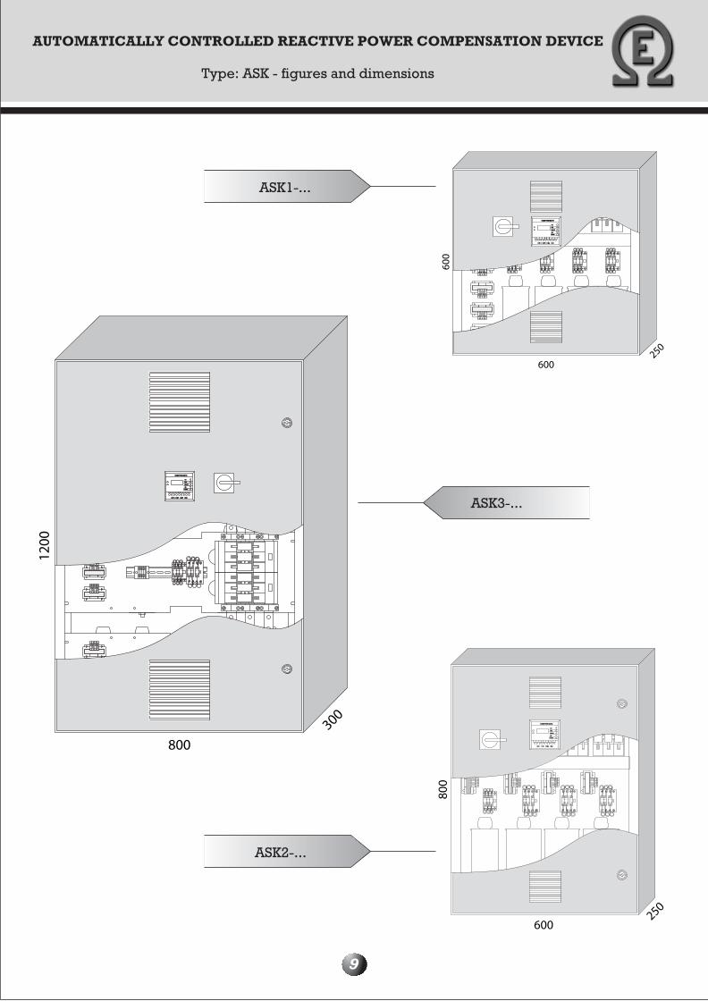
AUTOMATICALLY CONTROLLED REACTIVE POWER COMPENSATION DEVICE
Type: ASK - figures and dimensions
9
250
600
600
I(Ax10)I(Ax10)
SETSET
AlarmAlarm
d%d%
COMPUTER 8d-96COMPUTER 8d-96
I (A)I (A)
coscos
250
600
800
SETSET
I (A)I (A)
coscos
I(Ax10)I(Ax10)
AlarmAlarm
d%d%
COMPUTER 8d-96COMPUTER 8d-96
800
1200
300
SETSET
d%d%
AlarmAlarm
I(Ax10)I(Ax10)
COMPUTER 8d-96COMPUTER 8d-96
coscos
I (A)I (A)
ASK3-...
ASK1-...
ASK2-...
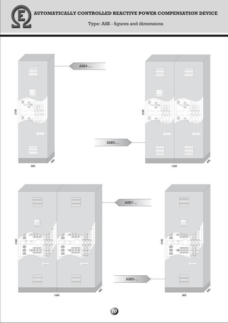
ASK4-...
ASK6-...
ASK7-...
ASK5-...
400400
800800
2100
2100
400400
2100
2100
16001600
600600
400400
2100
2100
400400
12001200
2100
2100
AUTOMATICALLY CONTROLLED REACTIVE POWER COMPENSATION DEVICE
Type: ASK - figures and dimensions
10
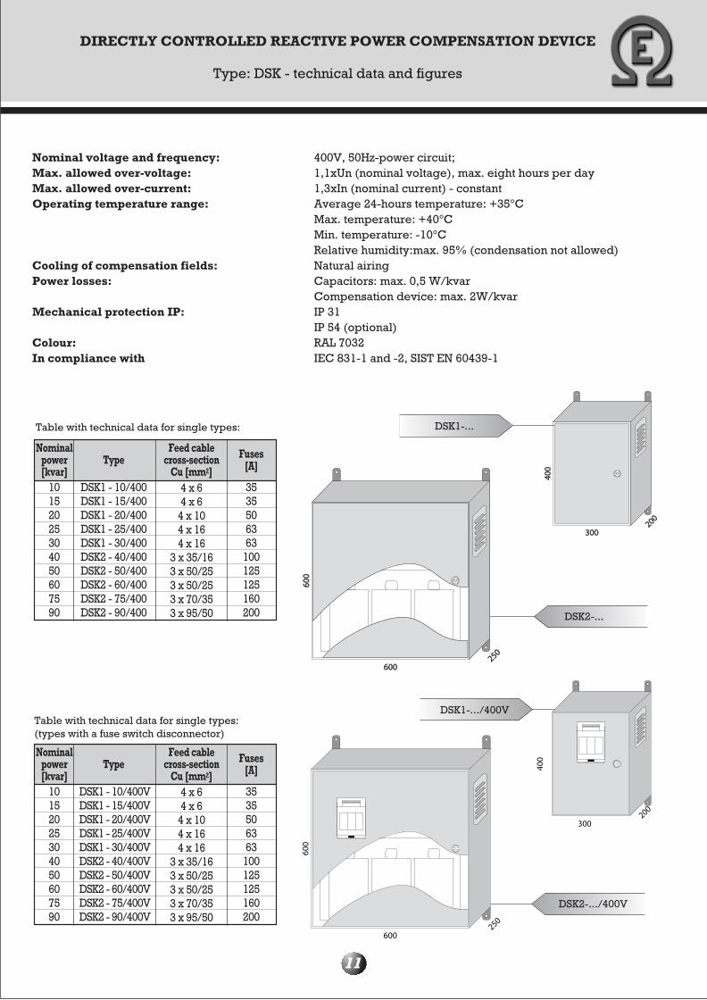
DSK2-...
DSK1-...
DSK1-.../400V
DSK2-.../400V
DIRECTLY CONTROLLED REACTIVE POWER COMPENSATION DEVICE
Type: DSK - technical data and figures
11
Nominal voltage and frequency: 400V, 50Hz-power circuit; Max. allowed over-voltage: 1,1xUn (nominal voltage), max. eight hours per dayMax. allowed over-current: 1,3xIn (nominal current) - constantOperating temperature range: Average 24-hours temperature: +35°C Max. temperature: +40°C Min. temperature: -10°C Relative humidity:max. 95% (condensation not allowed)Cooling of compensation fields: Natural airingPower losses: Capacitors: max. 0,5 W/kvar Compensation device: max. 2W/kvarMechanical protection IP: IP 31 IP 54 (optional)Colour: RAL 7032In compliance with IEC 831-1 and -2, SIST EN 60439-1
Table with technical data for single types:
Nominalpower[kvar]
10 15 20 25 30 40 50 60 75 90
DSK1 - 10/400 DSK1 - 15/400 DSK1 - 20/400 DSK1 - 25/400 DSK1 - 30/400 DSK2 - 40/400 DSK2 - 50/400 DSK2 - 60/400 DSK2 - 75/400 DSK2 - 90/400
4 x 6 4 x 6
4 x 10 4 x 16 4 x 16
3 x 35/16 3 x 50/25 3 x 50/25 3 x 70/35 3 x 95/50
35 35 50 63 63
100 125 125 160 200
TypeFeed cable
cross-sectionCu [mm2]
Fuses[A]
Nominalpower[kvar]
10 15 20 25 30 40 50 60 75 90
DSK1 - 10/400V DSK1 - 15/400V DSK1 - 20/400V DSK1 - 25/400V DSK1 - 30/400V DSK2 - 40/400V DSK2 - 50/400V DSK2 - 60/400V DSK2 - 75/400V DSK2 - 90/400V
4 x 6 4 x 6
4 x 10 4 x 16 4 x 16
3 x 35/16 3 x 50/25 3 x 50/25 3 x 70/35 3 x 95/50
35 35 50 63 63
100 125 125 160 200
TypeFeed cable
cross-sectionCu [mm2]
Fuses[A]
Table with technical data for single types:(types with a fuse switch disconnector)
600600
600
600
250250
400
400
300300200200
600
600
250
200
300
400
12
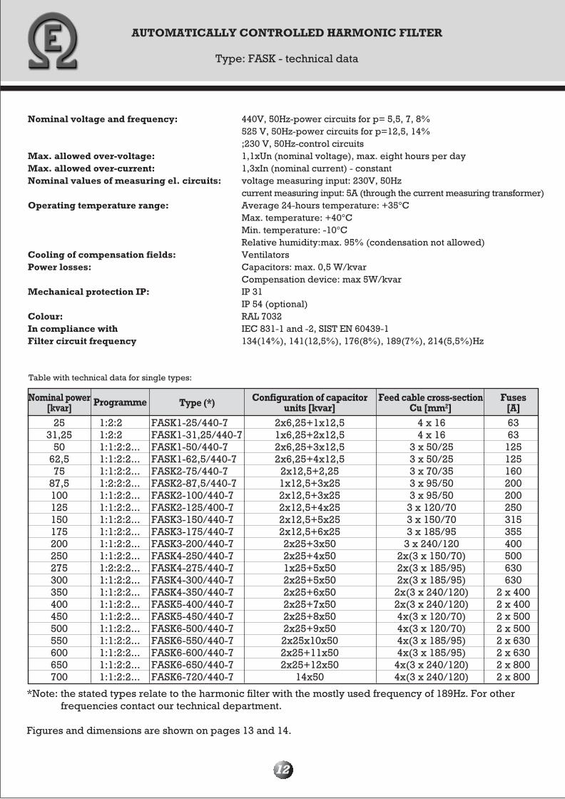
Nominal voltage and frequency: 440V, 50Hz-power circuits for p= 5,5, 7, 8% 525 V, 50Hz-power circuits for p=12,5, 14% ;230 V, 50Hz-control circuits Max. allowed over-voltage: 1,1xUn (nominal voltage), max. eight hours per dayMax. allowed over-current: 1,3xIn (nominal current) - constantNominal values of measuring el. circuits: voltage measuring input: 230V, 50Hz current measuring input: 5A (through the current measuring transformer)Operating temperature range: Average 24-hours temperature: +35°C Max. temperature: +40°C Min. temperature: -10°C Relative humidity:max. 95% (condensation not allowed)Cooling of compensation fields: VentilatorsPower losses: Capacitors: max. 0,5 W/kvar Compensation device: max 5W/kvarMechanical protection IP: IP 31 IP 54 (optional)Colour: RAL 7032In compliance with IEC 831-1 and -2, SIST EN 60439-1Filter circuit frequency 134(14%), 141(12,5%), 176(8%), 189(7%), 214(5,5%)Hz
AUTOMATICALLY CONTROLLED HARMONIC FILTER
Type: FASK - technical data
Table with technical data for single types:
Nominal power[kvar] Programme Type (*) Configuration of capacitor
units [kvar]Feed cable cross-section
Cu [mm2]Fuses
[A]25
31,25 50
62,5 75
87,5 100 125 150 175 200 250 275 300 350 400 450 500 550 600 650 700
1:2:2 1:2:2 1:1:2:2... 1:1:2:2... 1:1:2:2...1:2:2:2...1:1:2:2...1:1:2:2...1:1:2:2... 1:1:2:2... 1:1:2:2...1:1:2:2...1:2:2:2...1:1:2:2...1:1:2:2... 1:1:2:2... 1:1:2:2...1:1:2:2...1:1:2:2...1:1:2:2...1:1:2:2... 1:1:2:2...
FASK1-25/440-7FASK1-31,25/440-7 FASK1-50/440-7 FASK1-62,5/440-7 FASK2-75/440-7 FASK2-87,5/440-7 FASK2-100/440-7 FASK2-125/400-7 FASK3-150/440-7FASK3-175/440-7FASK3-200/440-7FASK4-250/440-7FASK4-275/440-7FASK4-300/440-7FASK4-350/440-7FASK5-400/440-7FASK5-450/440-7FASK6-500/440-7FASK6-550/440-7FASK6-600/440-7FASK6-650/440-7FASK6-720/440-7
2x6,25+1x12,5 1x6,25+2x12,5 2x6,25+3x12,5 2x6,25+4x12,5
2x12,5+2,25 1x12,5+3x25 2x12,5+3x25 2x12,5+4x25 2x12,5+5x25 2x12,5+6x25 2x25+3x50 2x25+4x50 1x25+5x50 2x25+5x50 2x25+6x50 2x25+7x50 2x25+8x50 2x25+9x50 2x25x10x50 2x25+11x50 2x25+12x50
14x50
4 x 16 4 x 16
3 x 50/25 3 x 50/25 3 x 70/35 3 x 95/50 3 x 95/50
3 x 120/703 x 150/70 3 x 185/95
3 x 240/120 2x(3 x 150/70)2x(3 x 185/95)2x(3 x 185/95)
2x(3 x 240/120) 2x(3 x 240/120) 4x(3 x 120/70)4x(3 x 120/70) 4x(3 x 185/95) 4x(3 x 185/95)
4x(3 x 240/120) 4x(3 x 240/120)
63 63
125 125 160200 200 250 315 355 400 500 630 630
2 x 400 2 x 400 2 x 500 2 x 500 2 x 630 2 x 630 2 x 800 2 x 800
*Note: the stated types relate to the harmonic filter with the mostly used frequency of 189Hz. For other frequencies contact our technical department.
Figures and dimensions are shown on pages 13 and 14.

13
AUTOMATICALLY CONTROLLED HARMONIC FILTER
Type: FASK - figures and dimension
FASK1-...
FASK2-...
800800
1200
1200
300300
SETSET
d%d%
AlarmAlarm
I(Ax10)I(Ax10)
COMPUTER 8d-96COMPUTER 8d-96
coscos
I (A)I (A)
2100
2100
400400
600600
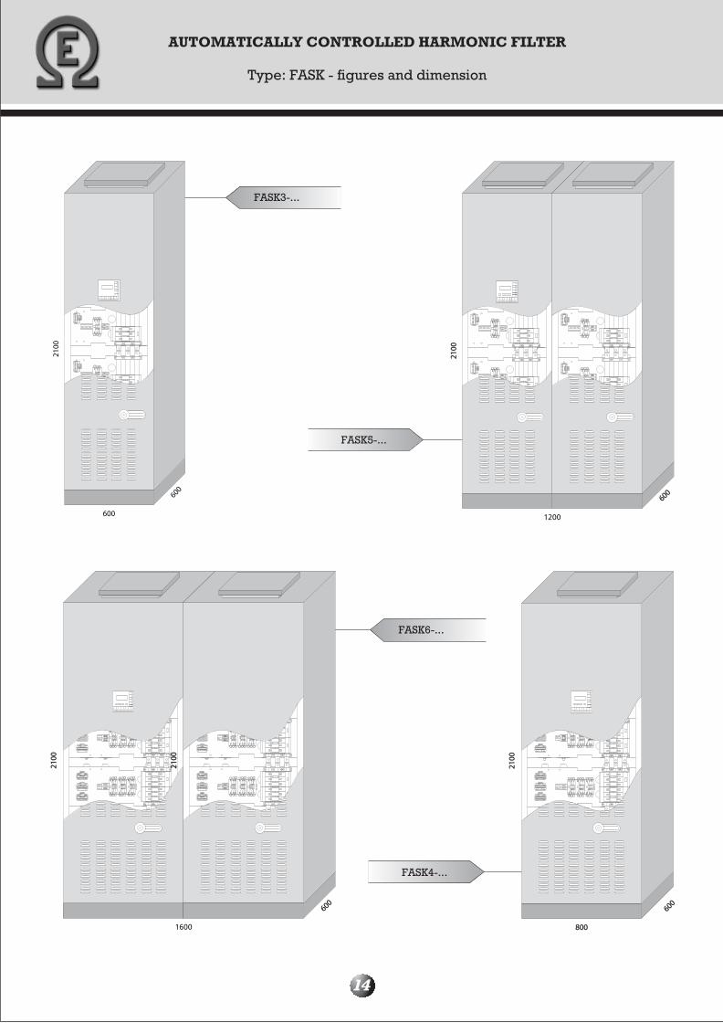
FASK3-...
FASK5-...
FASK6-...
FASK4-...
600
600
2100
2100
2100
800800
600600
2100
2100
600600
2100
2100
600600
2100
2100
AUTOMATICALLY CONTROLLED HARMONIC FILTER
Type: FASK - figures and dimension
14
1200
1600
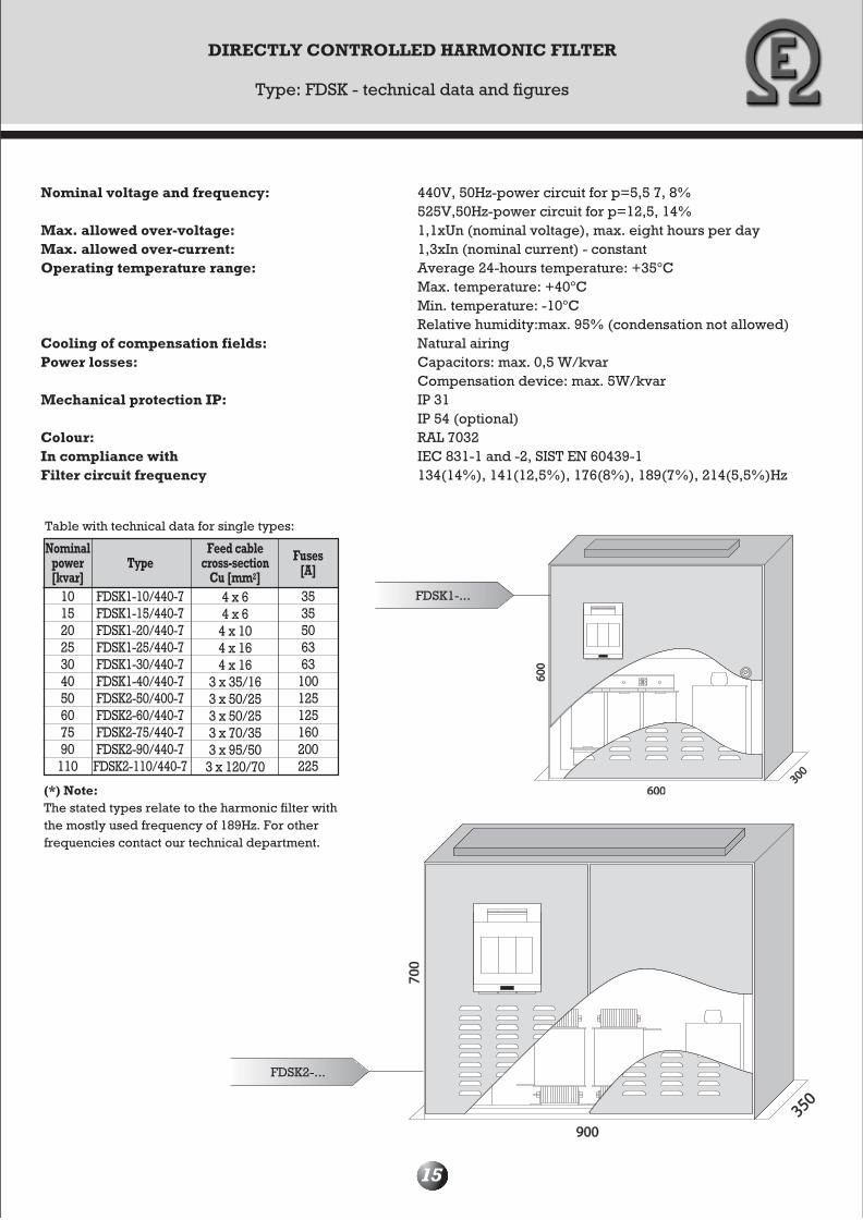
FDSK1-...
DIRECTLY CONTROLLED HARMONIC FILTER
Type: FDSK - technical data and figures
15
Nominal voltage and frequency: 440V, 50Hz-power circuit for p=5,5 7, 8% 525V,50Hz-power circuit for p=12,5, 14% Max. allowed over-voltage: 1,1xUn (nominal voltage), max. eight hours per dayMax. allowed over-current: 1,3xIn (nominal current) - constantOperating temperature range: Average 24-hours temperature: +35°C Max. temperature: +40°C Min. temperature: -10°C Relative humidity:max. 95% (condensation not allowed)Cooling of compensation fields: Natural airingPower losses: Capacitors: max. 0,5 W/kvar Compensation device: max. 5W/kvarMechanical protection IP: IP 31 IP 54 (optional)Colour: RAL 7032In compliance with IEC 831-1 and -2, SIST EN 60439-1Filter circuit frequency 134(14%), 141(12,5%), 176(8%), 189(7%), 214(5,5%)Hz
350350
700
700
900900
300300
600
600
600600
Table with technical data for single types:
Nominalpower[kvar]
10 15 20 25 30 40 50 60 75 90
110
FDSK1-10/440-7FDSK1-15/440-7 FDSK1-20/440-7 FDSK1-25/440-7 FDSK1-30/440-7 FDSK1-40/440-7 FDSK2-50/400-7 FDSK2-60/440-7 FDSK2-75/440-7 FDSK2-90/440-7
FDSK2-110/440-7
4 x 6 4 x 6
4 x 10 4 x 16 4 x 16
3 x 35/16 3 x 50/25 3 x 50/25 3 x 70/35 3 x 95/50
3 x 120/70
35 35 50 63 63
100 125 125 160 200225
TypeFeed cable
cross-sectionCu [mm2]
Fuses[A]
(*) Note: The stated types relate to the harmonic filter with the mostly used frequency of 189Hz. For other frequencies contact our technical department.
FDSK2-...

ELEKTROTEHNI©KO PODJETJELeskoπkova cesta 12, 1000 Ljubljana, SloveniaTel.: 00386 1 524-01-93, Fax: 00386 1 524-01-94, Mobil.: 00386 1 31/608-453, 00386 1 41/693-870E-mail: [email protected]
d.o.o.d.o.o.
OUR SERVICES:OUR SERVICES:
Manufacturing:Manufacturing:
• low-voltage compensation devices• high-voltage compensation devices• low-voltage switching systems, module and traditional types for industry and transformer stations
Setting up:Setting up:
• electrical power equipment• managing electrical power installations• transformer stations
Service of:Service of:
• electrical power installations• compensation devices
Measuring:Measuring:
• energy quantities and implementing registration of high harmonics in the network in terms of a correct setting of compensation and other devices
Constructing:Constructing:
• low-voltage switching systems


![Reactive Power Compensation[1]](https://static.documents.pub/doc/80x56/577ccf3f1a28ab9e788f40c0/reactive-power-compensation1.jpg)


