Nikolay Shurov Department of electrotechnical complexes
Novosibirsk state technical university Novosibirsk, Russia [email protected]
Abstract — The paper reviews research data of reactive power compensation for Metro electric power substations. According to comparative analysis of Metro, it is necessary to compensate reactive power in order to reduce its the negative consequences, which are also presented. Reactive power compensation ensures compliance with the condition of reactive power balance, contributes to the reduction of electricity losses in electrical grids, increases their throughput, allows for voltage regulation through the use of compensating devices, etc. The control system for suggested device has been developed; in addition mathematic simulation has been carried out as a result of which power factor of substation has been increased to 0.97-0.99.
Keywords — reactive power, active power filter, high frequency distortion, compensation
I. INTRODUCTION
With the worldwide energy price increase, the reduction of losses in electricity transmission and transformation and rational uses of energy are priority areas of science and technology. Nowadays metro is one of the largest consumers of electricity in modern cities. Therefore, it is imperative that metro will be energy efficient. Also, in addition to the quantitative indicators of energy, electric power quality indicators become important too. One of the main quality indicators is the power factor which characterized the reactive power presence of the consumer. High-frequency distortions, thus arising, and actively inductive type of load, which is the cause of current phase shift in terms of voltage are the reason for low value of metro substation power factor. All energy users of metro can be roughly divided into two groups.
Fig. 1. Histogram of statistical density probability and the graph of statistical functions for power factor of first group of loads.
The first group is loads having a low but constant power factor within 24 hours. They are such users as escalators, ventilation, lighting, pumps etc. (Fig. 1).
Up to 40-50% of energy consumed by metro is for this user group [7]. The key factor affecting negatively the energy quality in the present group is current phase shift in terms of voltage. The second group is electric trains, the feeders wherein have a higher but variable over wide range power factor (Fig. 2).
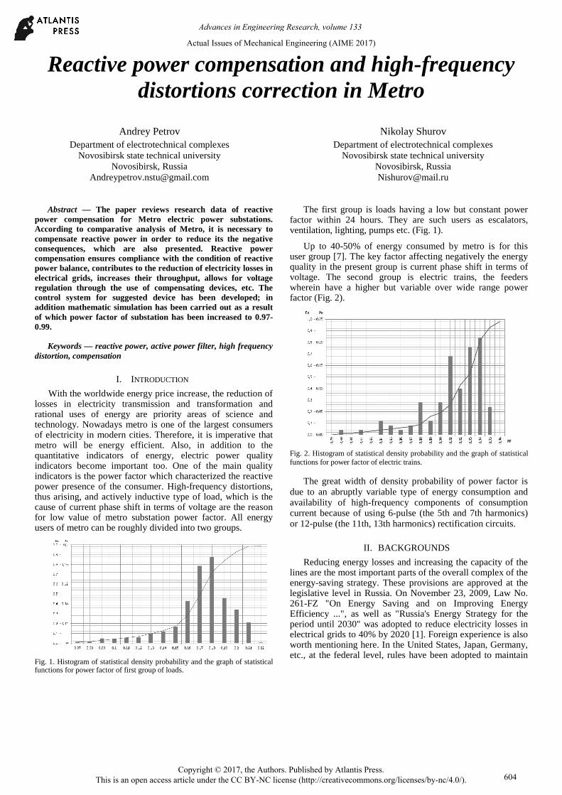
Fig. 2. Histogram of statistical density probability and the graph of statistical functions for power factor of electric trains.
The great width of density probability of power factor is due to an abruptly variable type of energy consumption and availability of high-frequency components of consumption current because of using 6-pulse (the 5th and 7th harmonics) or 12-pulse (the 11th, 13th harmonics) rectification circuits.
II. BACKGROUNDS
Reducing energy losses and increasing the capacity of the lines are the most important parts of the overall complex of the energy-saving strategy. These provisions are approved at the legislative level in Russia. On November 23, 2009, Law No. 261-FZ "On Energy Saving and on Improving Energy Efficiency ...", as well as "Russia's Energy Strategy for the period until 2030" was adopted to reduce electricity losses in electrical grids to 40% by 2020 [1]. Foreign experience is also worth mentioning here. In the United States, Japan, Germany, etc., at the federal level, rules have been adopted to maintain
Actual Issues of Mechanical Engineering (AIME 2017)
the power factor at a high level, with a tendency to a further increase to 0.98-0.99 [7].
The quality of electricity in the grids depends on not only the power plants that generate it, but also on consumers. In the most general case, the influence of consumers is characterized by:
• The presence of reactive elements, electric motors and other equipment, which causes a phase shift of the current relative to the voltage.
• Non-sinusoidal current consumption, which introduces higher harmonics into the grid.
• Asymmetric phase loading in 0.4 kV lines.
The reactive energy, circulating between the generator and the consumer through the grid, is not a direct loss, as it is not consumed by the load, but is the cause of the following negative impacts:
• The transfer of reactive energy leads to additional loading of network elements (mainly feed lines), which reduces their throughput.
• The effective value of the line current increases, which leads to an increase of losses in all links of the circuit, which also contributes to reduction of the voltage of electricity consumers.
With non-sinusoidal current consumption, a negative effect on the grid is characterized by the appearance of higher harmonics, which are the cause of:
• Distortion of the supply voltage shape.
• Increased losses in transformers due to losses by hysteresis and the appearance of eddy currents.
• Additional losses in lines, due to surface effect and proximity effect.
• Occurrence of resonant phenomena in the grids.
• Jamming in near communications.
• Promotion of more rapid insulation aging.
With asymmetric power consumption in three-phase four-wire systems the grid is characterized by:
• Increase current in the neutral conductor.
• Occurrence harmonics multiple of three in the primary grid.
• Distortion of the supply voltage form.
• Voltage slump in overloaded phases.
The revealed peculiarities of consumers' influence on the quality of electricity is the basis for considering the issue of measures that will allow one to increase such indicators as power factor, nonlinear distortion factor and cosφ.
Technical measures of power factor increasing include changes related to the replacement of equipment, circuit
diagrams of power supply, attraction of additional devices capable to improve the quality of electricity supply.
Technical measures to increase the power factor for the subway are:
• Application of energy-efficient electrical circuits for power supply.
• Replacement of escalators asynchronous engines with synchronous motors with permanent magnets.
• Application of new solutions in the field of AC motor control.
• Reactive power compensation.
• Correction of high-frequency harmonic distortion.
Traditional ways of reactive power compensation, such as applying capacitor banks (CB), passive filters etc. except for slow response, could be the cause of emerging electromagnetic resonance processes [9].
TABLE I. Power factor compensation matching.
Function: Type of compensators CB STP STATCOM APF
Compensation on the main harmonic
– step 10ms 0.2ms
Higher harmonics correction
– – – 50
harmonics
Adequation of phase load
– – + +
Smoothing active power peaks
– – – +
Higher-end static thyristor compensators (STC) and
STATCOMs do not provide the shaping of compensation impact in real-time and distortion power compensation [10]. Because of these reasons, there is a shift to active power correction, particularly higher harmonic neutralization, by the active power filter (APF) in recent years [Table 1]. In the device, the generation of compensation impact, reciprocal to harmonic component value due to compensation, is implemented.
III. PROBLEM DEFINITION
The goal of this research is the design of hybrid reactive power compensation conforming to specifications of target user. To fulfill a set goal, the following tasks are solved in the research: to offer and describe the operation of hybrid reactive power compensation, to consider the question of developing the control system of hybrid filter, to fulfill mathematic simulation of the device as suggested in Matlab Simulink.
IV. THEORY
With the development of power semiconductor technology at the beginning of the 21st century, it became possible to produce not only reactive power compensation, but also correction of high-frequency harmonic distortion. Devices that allow performing such tasks were called active power filters. This device, based on information about the grid's energy
Advances in Engineering Research, volume 133
605
parameters coming in real time, realizes the consumption or generation of reactive power.
Also at the same time, receiving information about the harmonic composition of the network current, it produces a correction of nonlinear distortions (Fig. 3).
Fig. 3. Change of current function by active power filter.
To date, APF is connected to grid by two main ways: in-series and in parallel. In the first case, APF is calculated by total current of a consumer and controlled by phase to earth voltage, resulting in high capacity, which is equivalent of high cost. APF connection in-parallel is more common because of the more flexible approach to choosing nominal power, compensation possibility of various pulse types, imbalance and phase shift, and harmonic distortions of converter units [8].
APF consists of a three-phase inverter, the crucial components of which are Insulated Gate Bipolar Transistor (IGBT), smoothing – inductors, capacitor bank (CB) which is a source of reactive energy, and also microprocessor which based on information from current and voltage sensors generate control signals for IGBT. Initial charge of the capacitor bank is constructed without using supplementary power supply.
A self-excited inverter is usually actualized using a two-level circuit of IGBT-inverter. The inductance value of the smoothing inductor is calculated due to smoothing conditions of pulse width modulation (PWM) and the possibility to secure high current range.
APF could solve several parallel tasks simultaneously. Besides reactive power compensation in main harmonic and higher harmonic compensation, caused by nonlinear distortions, APF could accomplish load distribution between phases. This capability allows decreasing greatly the difference of potential between a neutral conductor and ground in the four-wire system. APF is insensitive to great changes of grid impedance, which can occur for instance when switching from mains supply to generating set feeding. The use of digital controllers provides reliability, versatility and system accuracy.
For reactive power compensation in the supply system of metro, one can use the hybrid reactive power compensator
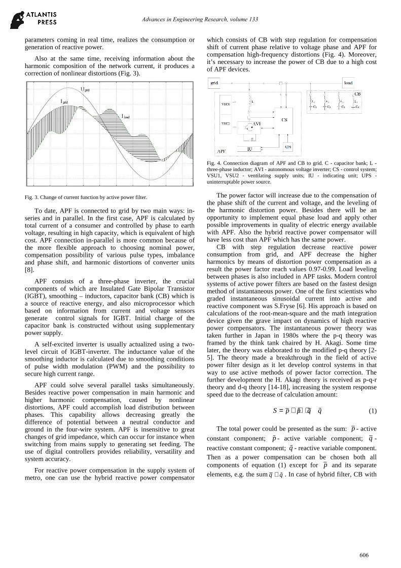
which consists of CB with step regulation for compensation shift of current phase relative to voltage phase and APF for compensation high-frequency distortions (Fig. 4). Moreover, it’s necessary to increase the power of CB due to a high cost of APF devices.
Fig. 4. Connection diagram of APF and CB to grid. C - capacitor bank; L - three-phase inductor; AVI - autonomous voltage inverter; CS - control system; VSU1, VSU2 - ventilating supply units; IU - indicating unit; UPS - uninterruptable power source.
The power factor will increase due to the compensation of the phase shift of the current and voltage, and the leveling of the harmonic distortion power. Besides there will be an opportunity to implement equal phase load and apply other possible improvements in quality of electric energy available with APF. Also the hybrid reactive power compensator will have less cost than APF which has the same power.
CB with step regulation decrease reactive power consumption from grid, and APF decrease the higher harmonics by means of distortion power compensation as a result the power factor reach values 0.97-0.99. Load leveling between phases is also included in APF tasks. Modern control systems of active power filters are based on the fastest design method of instantaneous power. One of the first scientists who graded instantaneous sinusoidal current into active and reactive component was S.Fryse [6]. His approach is based on calculations of the root-mean-square and the math integration device given the grave impact on dynamics of high reactive power compensators. The instantaneous power theory was taken further in Japan in 1980s where the p-q theory was framed by the think tank chaired by H. Akagi. Some time later, the theory was elaborated to the modified p-q theory [2-5]. The theory made a breakthrough in the field of active power filter design as it let develop control systems in that way to use active methods of power factor correction. The further development the H. Akagi theory is received as p-q-r theory and d-q theory [14-18], increasing the system response speed due to the decrease of calculation amount:
S p p q q= + + +ɶ ɶ (1)
The total power could be presented as the sum: p - active
constant component; pɶ - active variable component; q -
reactive constant component; qɶ - reactive variable component. Then as a power compensation can be chosen both all components of equation (1) except for p and its separate elements, e.g. the sumq q+ ɶ . In case of hybrid filter, CB with
Advances in Engineering Research, volume 133
606
step regulation compensates reactive constant
componentCB q≫ .
As the step connection of reactive source to grid does not provide an opportunity to compensate accurately all reactive constant component appears an uncompensated residue:
*q q qCB= − (2)
which will be compensated by APF in combination with qɶ .
*APF q q+ɶ≫ The control system of the hybrid reactive power
compensator is functionally as follows:
Fig. 5. Functional scheme of control system.
Park-Gorev transformation is a math approach to the description of energy characteristics in states dq0 [9-11]:
(u ju )( j ) jqP i i pp pdq d d d d= − − = − , (3)
wherep p , qp – real and fictitious power:
Re(P )p u i u ip q qdq d d= = + (4)
Im(P )q u i u ip q qdq d d= = − . (5)
Zero component power is:
0 0 0p u i=. (6)
A total power at states dq0 equals a full – power at states αβ:
Mathematical modeling of the hybrid filter operation was carried out in Matlab Simulink. Active-inductive load was energized from the three-phase three-wire source of the sinusoidal voltage, and one also introduced higher harmonics into the grid. In parallel to this system, a passive capacitive filter, which performed a phase shift of the current, and an active power filter that smoothed high-frequency nonlinear distortions were connected.
The simulation results are shown in Figure 6. Figure 6a shows the voltage and current of phase A without using filters, cosφ load is 0.6, the 5th, 7th, 11th and other harmonics are present. When a passive filter is connected, the phase of the current shifts to cosφ = 0.96, nonlinear distortions are present (Fig. 6b).
a)
b)
c)
Fig.6. Simulations of connection hybrid filter to grid.
After the active filter introduces higher harmonics into the grid, leveling the nonlinear distortions of the load current, resulting current - the current of the grid (Fig. 6c) has a sinusoidal shape with a fundamental harmonic equal to 96% of the first harmonic of the load current. Besides correction of the
Advances in Engineering Research, volume 133
607
current shape, APF performs a more accurate shift of the phase current characteristic, as a result of which cosφ reaches values of 0.99. The compensation current is 56% of the load current. The higher harmonics constitute <1% of the fundamental.
Fig.7. Experimental current and voltage oscillogram of grid with hybrid filter
For hybrid filter tests, a complex shape load was created. It includes both phase shift and nonlinear distortion. When the hybrid filter is switched on, the phase of the current is aligned with the phase of the voltage, as well as the curve fitting. In the experiment, the effective value of current consumption from grid was decreased three times.
Fig.8. Experimental voltage oscillogram of grid before and after hybrid filter connection
The results of the experiment confirm that the hybrid filter can improve the quality of electricity in the grid and reduce the current consumption from the source of energy by compensating the reactive energy and correction of high-frequency distortions.
VI. CONCLUSION
The problem of the influence of reactive power on the industrial grid is widely considered. The main negative factors are a phase shift of the current relative to the voltage and high frequency distortions. A comparative analysis of the existing reactive power compensation equipment was carried out where an active power filter has an advantage.
During the research, a hybrid device of reactive power compensation consisting of the passive filter-capacitor bank with a step regulation and active power factor corrector was proposed. The control system of this device and mathematic simulation of APF in Matlab Simulink are also represented. The simulation and experiments results show an increase of the power factor system to the level of 0.97-0.99. The further research will be aimed to study the system of controlling filters with a focus on improving its dynamic properties.
References [1] Federal Law No. 261-FZ of November 23, 2009 (as amended on July 13,
2015) "On Energy Saving and on Improving Energy Efficiency and on Amending Certain Legislative Acts of the Russian Federation".
[2] H. Akagi, “Modern active filters and traditional passive filters” Bulletin of the polish academy of sciences technical sciences, Vol. 54, No. 3, 2006.
[3] H. Akagi, E. H. Watanabe, M.Aredes, “Instantaneous power theory and applications to power conditioning” IEEE Press, vol. 2, p. 389
[4] H. Akagi, Active Harmonic Filters, Proceedings of the IEEE, Vol. 93, № 12, pp. 2128 – 2141, 2005.
[5] Akagi H., Kanazawa Y., Nabae A. Generalized theory of the instantaneous reactive power in three-phase circuits // Proceedings of the International Power Electronics Conference (IPEC'83), Japan, Tokio, 1983, Tokyo, pp. 1375–1386, 1983. Doi: 10.1002/eej.4391030409.
[6] S. Fryze, Wirk-, blind-, und scheinleistung in elektrischen stromkreisen mit nicht-sinusformigem verlauf von strom und spannung, Elektrotechnische Zeitschrift, Vol. 53, № 25, pp. 596–599, 1932.
[7] Andrey A. Petrov, Nadezhda A. Logutenko, The analysis of reactive power in metro. IFOST-2016: Mechatronics, Electrical Engineering and Power Electronics, Part 2, pp. 121-123, 2016.
[8] Petrov A.A., Schurov N.I. Shtang A.A. Electricity quality improving in metro. Proceedings of the Russian higher school Academy of sciences, no. 4 (33), pp. 80–87, 2016. doi:10.17212/1727-2769-2016-4-80-87
[9] O. V. Nos, Control strategy of active power filter for ineffective instantaneous power compensation, The 15 international conference of young specialists on micro/nanotechnologies and electron devices, Novosibirsk : IEEE Press, 2014, pp. 370–374.
[10] O. V. Nos, S. A. Kharitonov, A system to control power currents of ineffective instantaneous power compensation, Russian Electrical Engineering, Vol. 86, № 2, pp. 72–78, 2015.
[11] K.A. Shalygin, O.V. Nos, Technical realization of the energy conservation principles on the basis of power active filters, Proceedings of the VIII International (XIX All-Russian) Conference of the automated electric driver AEP 2014, Saransk: Mordov University Press, Vol. 2, pp. 28-32, 2014.
[12] L. Saribulut, A. Teke, M. E. Meral, M. Tumay, Active power filter: review of converter topologies and control strategies, Gazi University Journal of Science, Vol. 24, № 2, pp. 283–289, 2011.
[13] J. L. Willems, A new interpretation of the Akagi-Nabae power components for nonsinusoidal three-phase situations, IEEE Transactions on Instrumen-tation and Measurement, Vol. 41, № 4, pp. 523–527, 1992.
[14] J. L. Afonso, M. Aredes, E. H. Watanabe, J. S. Martins, Shunt active filter for power quality improvement, Electricity for a sustainable urban development : proc., the intern. conf., UIE 2000, Portugal, Lisboa, 1–4 Nov. 2000, Lisboa, 2000, pp. 683–691.
[15] L. Saribulut, A. Teke, M. E. Meral, M. Tumay, Active power filter: review of converter topologies and control strategies, Gazi University Journal of Science, Vol. 24, № 2, pp. 283–289, 2011.
[16] J. L. Afonso, M. J. Sepulveda Freitas, J. S. Martins, P-q theory power components calculations, IEEE international symposium on industrial electronics, Brazil, Rio de Janeiro, Press, Vol. 1, pp. 385–390, 2003.
[17] R. S. Herrera, P. Salmerón, J. R. Vázquez, S. P. Litrán, A. Pérez, Generalized instantaneous reactive power theory in poly-phase power systems,The 13 European conference on power electronics and applications, EPE 2009. Spain, Barcelona, 2009, 10 p.
[18] H. Kim, F. Blaabjerg, D. Bak-Jensen, J. Choi, Instantaneous power compensation in three-phase systems by using p–q–r theory, The IEEE 32 annual power electronics specialists conference, PESC 2001, Canada, Vancouver, Hong Kong : IEEE Press, Vol. 2., pp. 478–485.
[19] H. Kim, F. Blaabjerg, D. Bak-Jensen, J. Choi, Instantaneous power compensation in three-phase systems by using p–q–r theory, IEEE Transactions on Power Electronics, № 5, pp. 701–710, 2002.