1 www.RMDinc.com Radiation Monitoring Devices Instrument Research & Development C.J. Stapels 1 , E.B. Johnson 1 , F. Augustine 2 , P. Barton 3 , D. Wehe 3 , E.C. Chapman, P. Dokhale, K Shah, & J. F. Christian 1 . Recent developments with CMOS SSPM photodetectors 1. Radiation Monitoring Devices: Watertown, MA 2. Augustine Engineering: Encinitas, CA 3. University of Michigan: Ann Arbor, MI
Transcript
1www.RMDinc.com
p
Radiation Monitoring Devices
Instrument Research& Development
C.J. Stapels1, E.B. Johnson1, F. Augustine2, P. Barton3, D. Wehe3, E.C. Chapman, P. Dokhale, K
Shah, & J. F. Christian1.
Recent developments with CMOS SSPM photodetectors
1. Radiation Monitoring Devices: Watertown, MA
2. Augustine Engineering: Encinitas, CA
3. University of Michigan: Ann Arbor, MI
2www.RMDinc.com
p
Radiation Monitoring Devices
Instrument Research& Development
CMOS highlights
• SSPM in Commercial CMOS provides:• Process control• Lower cost <1€ / mm2 (eng. run)• Libraries for component integration
• Target Application: Scintillator readout•Fill Factor (FF) maximization•Back illumination of thinned die•Position sensitivity in SSPM arrays
3www.RMDinc.com
p
Radiation Monitoring Devices
Instrument Research& Development
Fill Factor FX
Study increased fill factor effects:
• QE/DE• Dark noise• Cross talk• Afterpulsing
• Prototype array with varying pixel size and spacingQ FF Pixel
Size (μm)# of
PixelsPixelC (pF)
Q1 49% 30x30 961 0.13
Q2 61% 50x50 441 0.27
Q3 43% 50x50 324 0.33
Q4 29% 30x30 576 0.17 3mm
3mm
Q1 Q2
Q4 Q3
4www.RMDinc.com
p
Radiation Monitoring Devices
Instrument Research& Development
Fill Factor FX: dark counts
• Dark counts ~1Hz / V / μm2
• Simulated increased dark counts with a CW LED bank.
5www.RMDinc.com
p
Radiation Monitoring Devices
Instrument Research& Development
Fill Factor FX:Cross talk
• Ratio of 1 to 2 p.e. rates for XTM• XT Scales with pixel size, inversely with pixel
spacing• Increases with excess bias• Small excess noise?
1:2
ratio
, cor
rect
ed
6www.RMDinc.com
p
Radiation Monitoring Devices
Instrument Research& Development
Resolution vs. quadrant
• 137Cs resolution: LYSO on 1.5 mm SSPM• ~11% energy resolution
61 % 29%
7www.RMDinc.com
p
Radiation Monitoring Devices
Instrument Research& Development
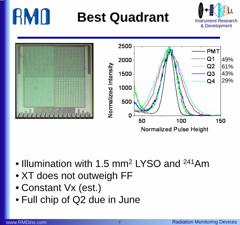
Best Quadrant
• Illumination with 1.5 mm2 LYSO and 241Am• XT does not outweigh FF• Constant Vx (est.)• Full chip of Q2 due in June
49% 61% 43% 29%
8www.RMDinc.com
p
Radiation Monitoring Devices
Instrument Research& Development
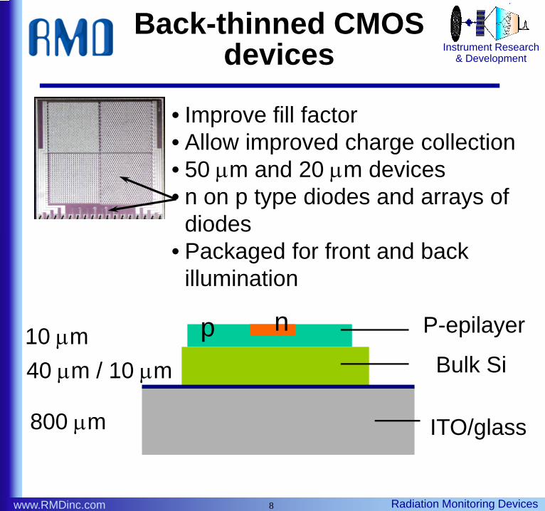
Back-thinned CMOS devices
• Improve fill factor• Allow improved charge collection• 50 μm and 20 μm devices• n on p type diodes and arrays of
diodes• Packaged for front and back
illumination
npBulk Si
ITO/glass 800 μm
10 μm40 μm / 10 μm
P-epilayer
9www.RMDinc.com
p
Radiation Monitoring Devices
Instrument Research& Development
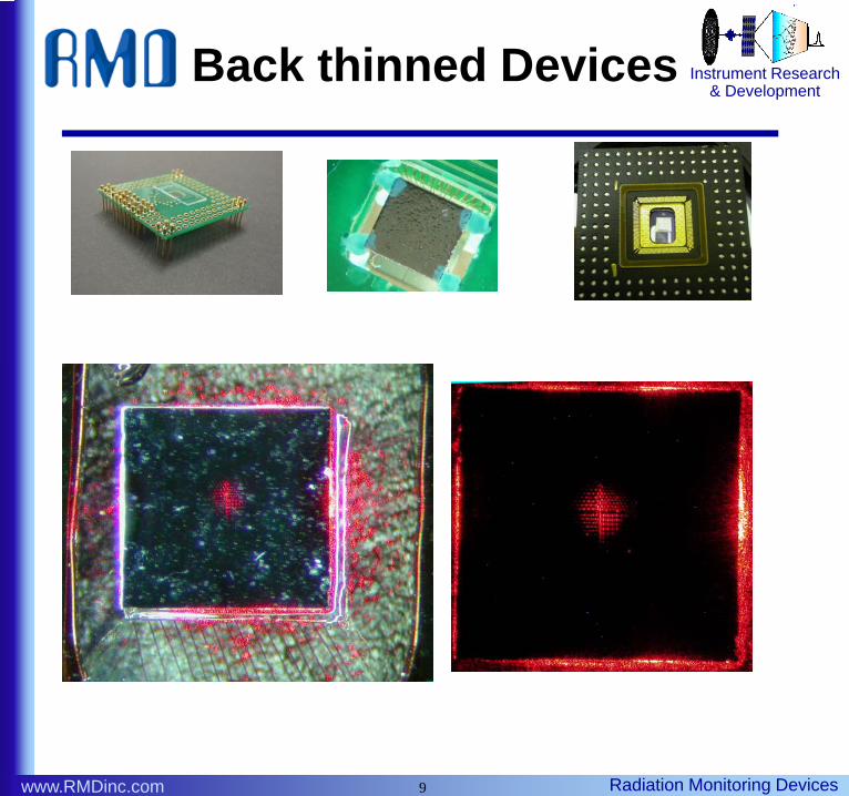
Back thinned Devices
10www.RMDinc.com
p
Radiation Monitoring Devices
Instrument Research& Development
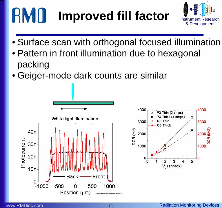
Improved fill factor
• Surface scan with orthogonal focused illumination• Pattern in front illumination due to hexagonal
packing• Geiger-mode dark counts are similar
11www.RMDinc.com
p
Radiation Monitoring Devices
Instrument Research& Development
Thinning improvements to QE
np Bulk Si
Substrate
• Improved QE in far red• Small improvement in charge collection from
substrate bias
12www.RMDinc.com
p
Radiation Monitoring Devices
Instrument Research& Development
Imaging SSPM
P P
P P
Vb
S1 S2
S3S4
Vb
P =
• Multiplexed position sensitive readout at four nodes
• Traditional resistor network does not preserve orthagonality of X and Y signals: mixing at nodes
13www.RMDinc.com
p
Radiation Monitoring Devices
Instrument Research& Development
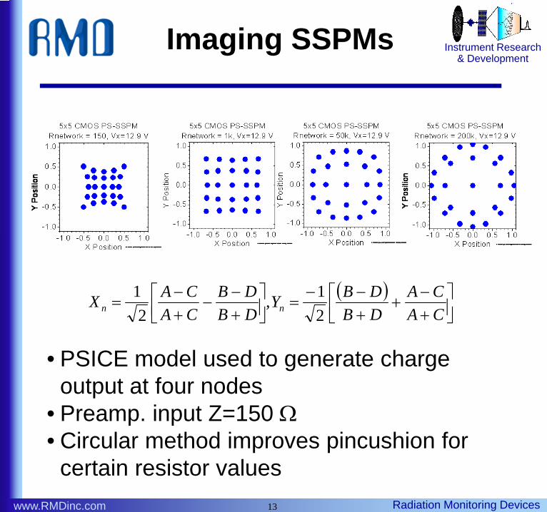
Imaging SSPMs
( )⎥⎦⎤
⎢⎣⎡
+−
++−−
=⎥⎦⎤
⎢⎣⎡
+−
−+−
=CACA
DBDBY
DBDB
CACAX nn 2
1,2
1
• PSICE model used to generate charge output at four nodes
• Preamp. input Z=150 Ω• Circular method improves pincushion for
certain resistor values
14www.RMDinc.com
p
Radiation Monitoring Devices
Instrument Research& Development
Imaging SSPMs
• Combined Anger and circular method produces further improvements
( ) ( )( )
( ) ( )( )DCBA
DCBAYDCBADACBX aa +++
+−+=
++++−+
= ,
15www.RMDinc.com
p
Radiation Monitoring Devices
Instrument Research& Development
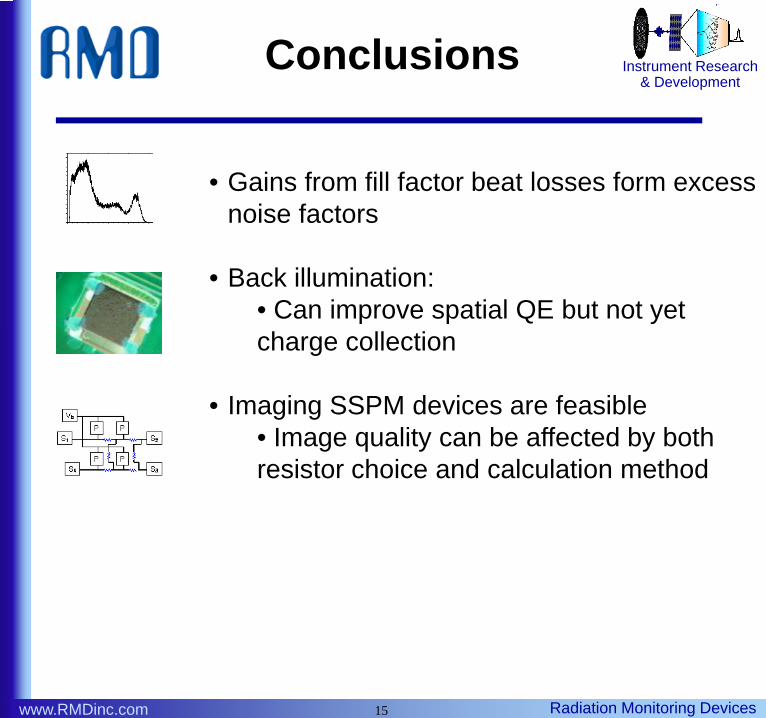
Conclusions
• Gains from fill factor beat losses form excess noise factors
• Back illumination:• Can improve spatial QE but not yet charge collection
• Imaging SSPM devices are feasible• Image quality can be affected by both resistor choice and calculation method