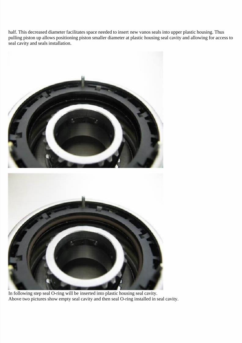
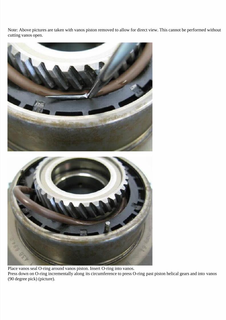
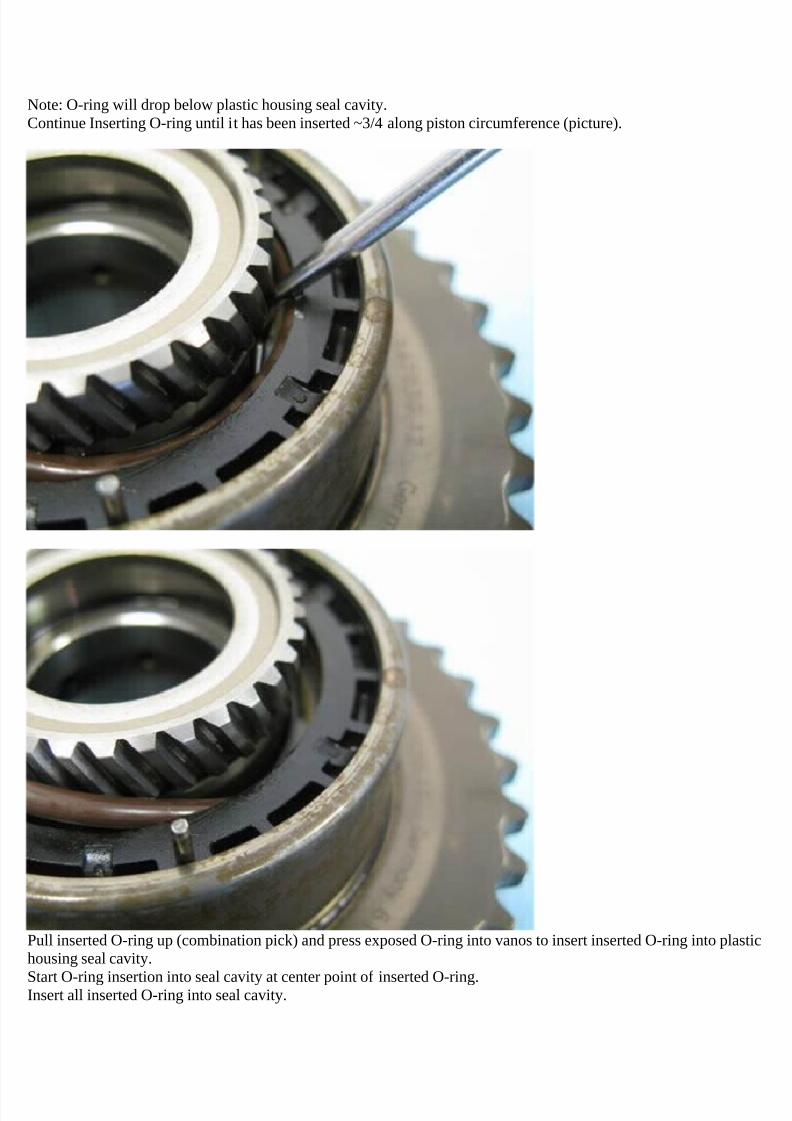
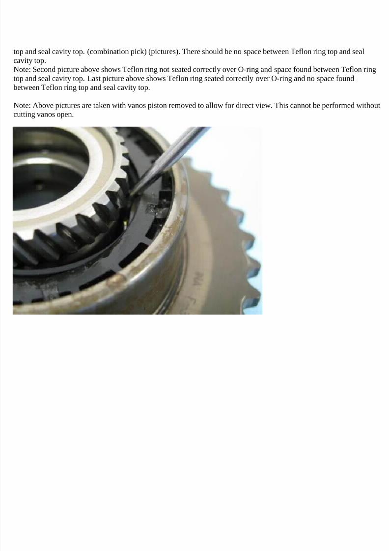
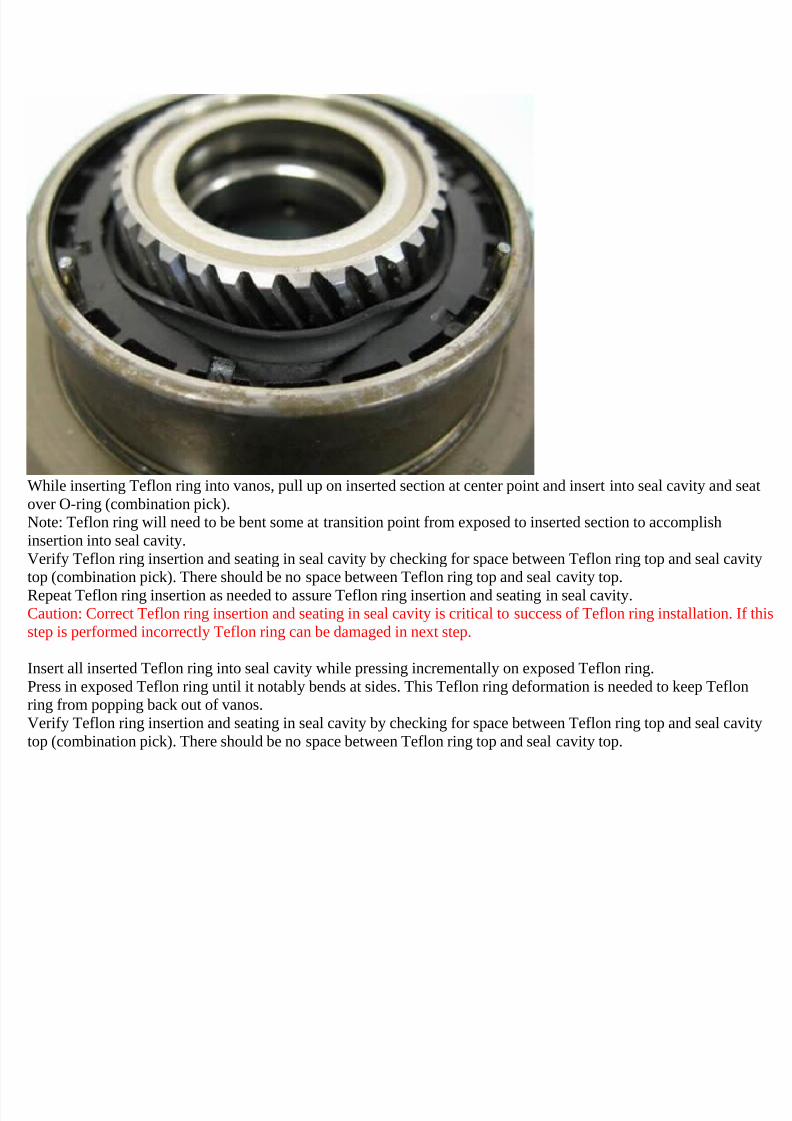
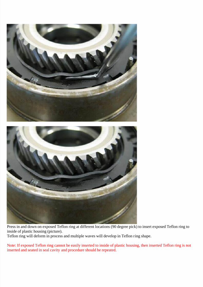
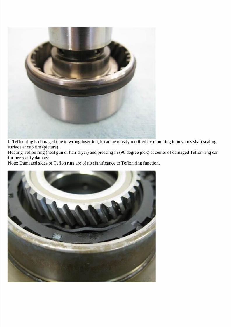
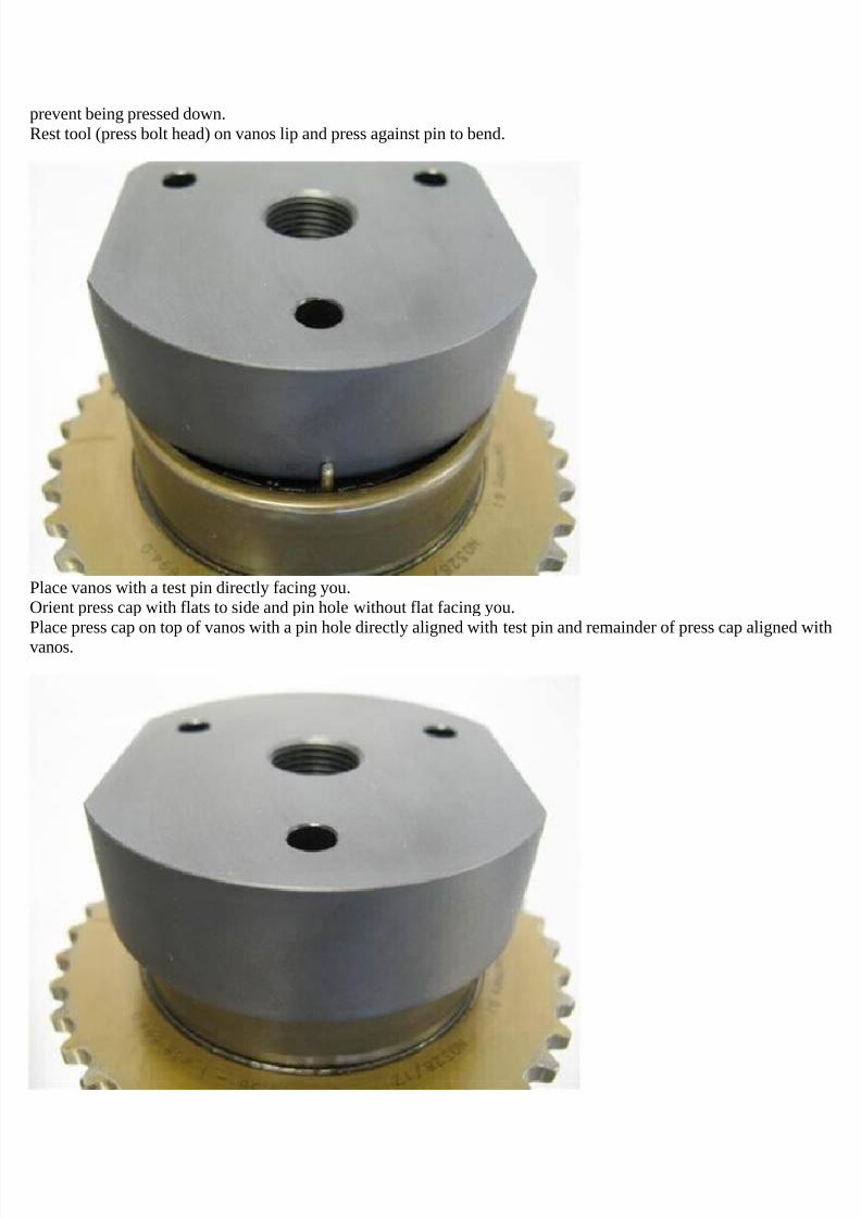
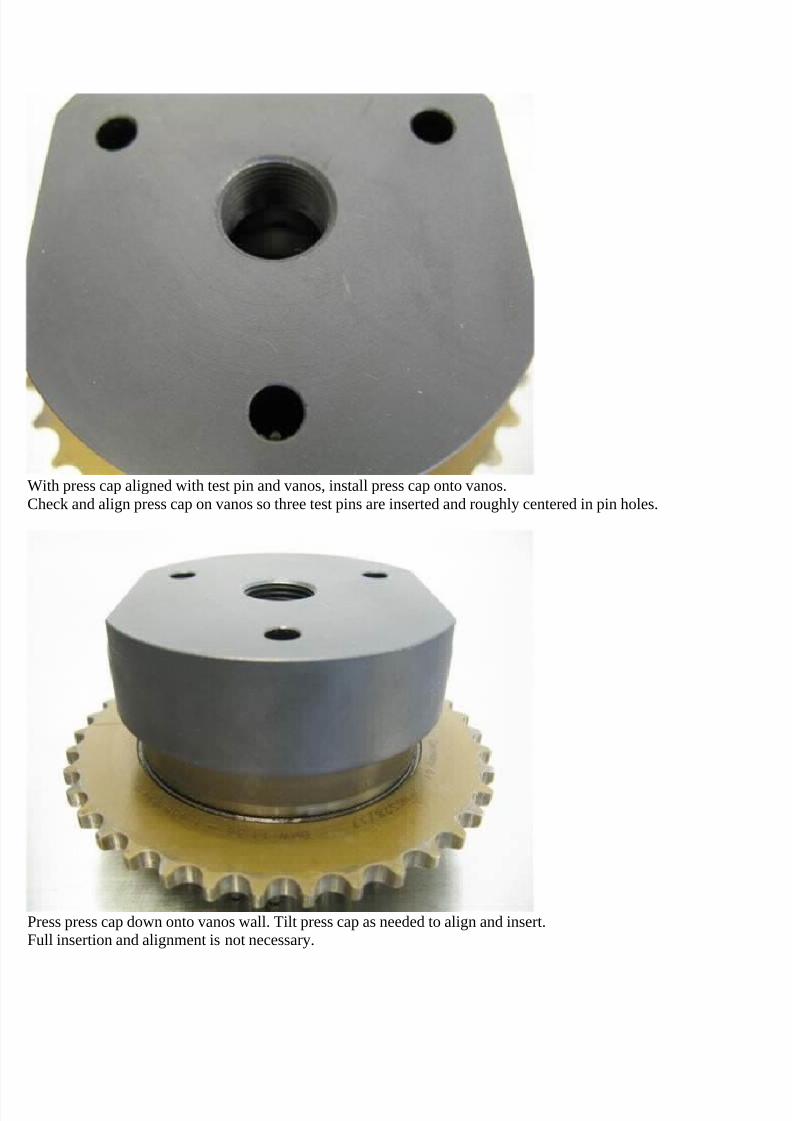
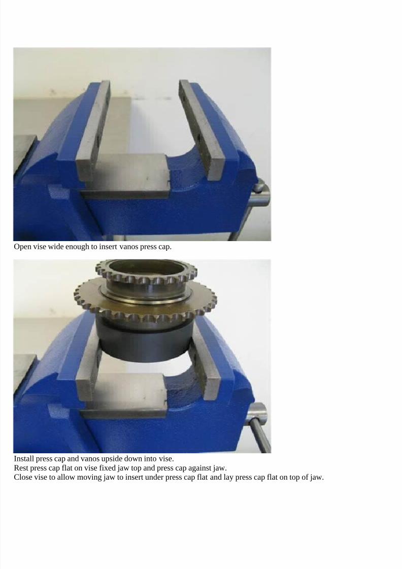
1. REMOVING AND CLEANING A MKI V THROT TLE BODY ( THROTTLE VAL VE CONTROL MODULE) The following outlines the procedure for removing and clea ning the drive-by-wire (DBW) throttle body (officially known a s the throttle valve control module) on a MKIV VW. The procedures were based on a 99.5 Jetta GLS VR6 and may be different on MKIV cars with different engines (1.8T, 2.0), body styles (Golf, GTI, New Beetle) and from different model years. Specifically, the procedures for removing and reinstalling the throttle body (herein referred to as TB) may differ due to slight differences in the design and orientation of the TB, however, the general removal/reinstallation procedures, as well as the cleaning procedures should be very similar. Please do these procedures at your own risk and be ready to make small adjustments while doing them. Also, please be observant while removing parts so that they go back together correctly. Before proceeding any further, I must make it clear that the DBW TBs used on the MKIV vehicles are high-precision, electro- mechanical devices. If you damage the servos and sensors which control the motion and position of the throttle valve (also known as the butterfly valve) while performing this procedure, there is a very great chance that your engine will not run correctly and the TB will need to be replaced. Since a new TB costs around $500, this is something that you will obviously want to prevent from happening. Therefore, be extremely careful when performing the procedure and heed the warnings and cautions that are given. I am not, nor will be held responsible if you mess up your TB while doing this procedure. This DIY is broken up into three part s... Part I deals with the removal of the TB from the intake circuit. Two methods for removing the TB are given. The first method is the "quick and dirty" method and requires that the least number of things be disconnected/removed in order to disconnect the TB. I did not perform this procedure, so I have no idea how long it takes. Nevertheless, I have supplied it for all the minimalist DIYers out there who like to keep things simple. (Note: If you follow this method, you may notice that the pictures posted for this method do not actually show anything disconnected. Please disregard these inconsistencies. Since I did not perform this procedure, I did not have the appropriate pictures and used those taken after everything was already reassembled. Just follow the written directions, using the photos only as a reference, and you should have no problems.) The second method is the "slow and thorough" method and requires that significantly more things be disconnected. The advantages of this method are that it (1) allows various other parts of the intake system, such as the main intake tube and PCV circuit to be examined and cleaned and (2) unclutters the "workspace", making it significantly easier to remove the coolant lines from the TB. This method is the one that I followed when cleaning my TB and I recommend that others use it as well. If you're familiar with this area of the engine bay, it will take approximately 30-60 mins to remove the TB using this method. Part II deals with the cleaning of the TB. The cleaning procedure should take 30-60 mins or more, depending greatly on how dirty your TB is and how careful and thorough you are when cleaning it. Part III deals with the adaptation of the TB to the engine control module (ECM) using a VAG-COM or other suitable scan tool. It is not absolutely necessary to perform this procedure, however doing so immediately following the reinstallation of the TB will help insure the smooth operation of the engine when it's first started. The tools/parts needed to perform the proce dures are: 1) 10mm wrench or socket (to disconnect negative battery lead) 2) Appropriate tool for removing hose clamps. If you have the stock spring clamps, a pair of channel lock pliers works great for this purpose since the jaws are roughly perpendicular to each other (helps prevent clamps from slipping in plier jaws) and the jaw width can be adjusted for each particular clamp size. If you have screw-type clamps, you'll need the appropriate screwdriver. 3) 5mm hex/Allen wrench (to remove TB from intake manifold) 4) Phillips screwdriver (only needed in "slow and thorough" method if removing MAF housing from air filter housing) 5) Flat blade screwdriver (to help remove spark plug wire boots from coilpack - not needed for "quick and dirty" method) 6) T30 Torx driver (to remove engine cover pieces - not needed for "quick and dirty" method) 7) Can of intake/TB cleaner 8) Q-tips or something similar (to gently scrub away the TB deposits) 9) Sheet of plain white paper 10) Paper towels or rags optional ... 11) New TB-to-manifold gasket. The Bentley manual instructs that this gasket should be replaced when the TB is removed, but more than likely it can be reused. Mine was still in excellent shape so I reused it. If you are uncomfortable doing this, purchase a new gasket. 12) VAG-COM or other suitable scan tool (for performing adaptation of TB to ECM).
Transcript
7/29/2019 Removing and Cleaning a Mkiv Throttle Body
REMOVING AND CLEANING A MKIV THROTTLE BODY (THROTTLE VALVE CONTROL MODULE)
The following outlines the procedure for removing and cleaning the drive-by-wire (DBW) throttle body (officially known asthe throttle valve control module) on a MKIV VW. The procedures were based on a 99.5 Jetta GLS VR6 and may be differenton MKIV cars with different engines (1.8T, 2.0), body styles (Golf, GTI, New Beetle) and from different model years.Specifically, the procedures for removing and reinstalling the throttle body (herein referred to as TB) may differ due to slight
differences in the design and orientation of the TB, however, the general removal/reinstallation procedures, as well as thecleaning procedures should be very similar. Please do these procedures at your own risk and be ready to make smalladjustments while doing them. Also, please be observant while removing parts so that they go back together correctly.
Before proceeding any further, I must make it clear that the DBW TBs used on the MKIV vehicles are high-precision, electro-mechanical devices. If you damage the servos and sensors which control the motion and position of the throttle valve (alsoknown as the butterfly valve) while performing this procedure, there is a very great chance that your engine will not runcorrectly and the TB will need to be replaced. Since a new TB costs around $500, this is something that you will obviouslywant to prevent from happening. Therefore, be extremely careful when performing the procedure and heed the warningsand cautions that are given. I am not, nor will be held responsible if you mess up your TB while doing this procedure.
This DIY is broken up into three parts...
Part I deals with the removal of the TB from the intake circuit. Two methods for removing the TB are given. The first methodis the "quick and dirty" method and requires that the least number of things be disconnected/removed in order to disconnectthe TB. I did not perform this procedure, so I have no idea how long it takes. Nevertheless, I have supplied it for all theminimalist DIYers out there who like to keep things simple. (Note: If you follow this method, you may notice that the picturesposted for this method do not actually show anything disconnected. Please disregard these inconsistencies. Since I did notperform this procedure, I did not have the appropriate pictures and used those taken after everything was alreadyreassembled. Just follow the written directions, using the photos only as a reference, and you should have no problems.) Thesecond method is the "slow and thorough" method and requires that significantly more things be disconnected. Theadvantages of this method are that it (1) allows various other parts of the intake system, such as the main intake tube andPCV circuit to be examined and cleaned and (2) unclutters the "workspace", making it significantly easier to remove thecoolant lines from the TB. This method is the one that I followed when cleaning my TB and I recommend that others use it aswell. If you're familiar with this area of the engine bay, it will take approximately 30-60 mins to remove the TB using thismethod.
Part II deals with the cleaning of the TB. The cleaning procedure should take 30-60 mins or more, depending greatly on howdirty your TB is and how careful and thorough you are when cleaning it.
Part III deals with the adaptation of the TB to the engine control module (ECM) using a VAG-COM or other suitable scan tool.It is not absolutely necessary to perform this procedure, however doing so immediately following the reinstallation of the TBwill help insure the smooth operation of the engine when it's first started.
The tools/parts needed to perform the procedures are:
1) 10mm wrench or socket (to disconnect negative battery lead)2) Appropriate tool for removing hose clamps. If you have the stock spring clamps, a pair of channel lock pliers works greatfor this purpose since the jaws are roughly perpendicular to each other (helps prevent clamps from slipping in plier jaws) andthe jaw width can be adjusted for each particular clamp size. If you have screw-type clamps, you'll need the appropriatescrewdriver.3) 5mm hex/Allen wrench (to remove TB from intake manifold)4) Phillips screwdriver (only needed in "slow and thorough" method if removing MAF housing from air filter housing)5) Flat blade screwdriver (to help remove spark plug wire boots from coilpack - not needed for "quick and dirty" method)6) T30 Torx driver (to remove engine cover pieces - not needed for "quick and dirty" method)7) Can of intake/TB cleaner8) Q-tips or something similar (to gently scrub away the TB deposits)9) Sheet of plain white paper10) Paper towels or rags
optional ...
11) New TB-to-manifold gasket. The Bentley manual instructs that this gasket should be replaced when the TB is removed,but more than likely it can be reused. Mine was still in excellent shape so I reused it. If you are uncomfortable doing this,
purchase a new gasket.12) VAG-COM or other suitable scan tool (for performing adaptation of TB to ECM).
7/29/2019 Removing and Cleaning a Mkiv Throttle Body
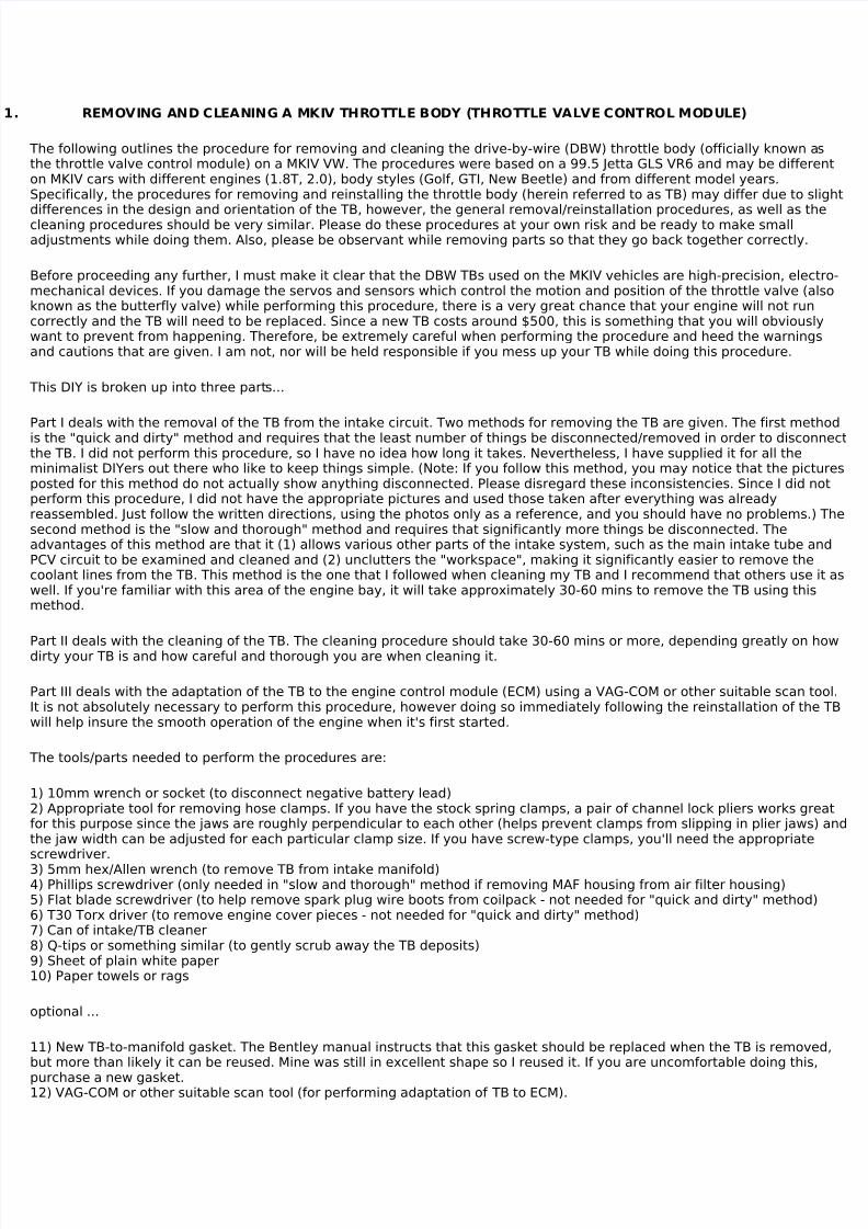
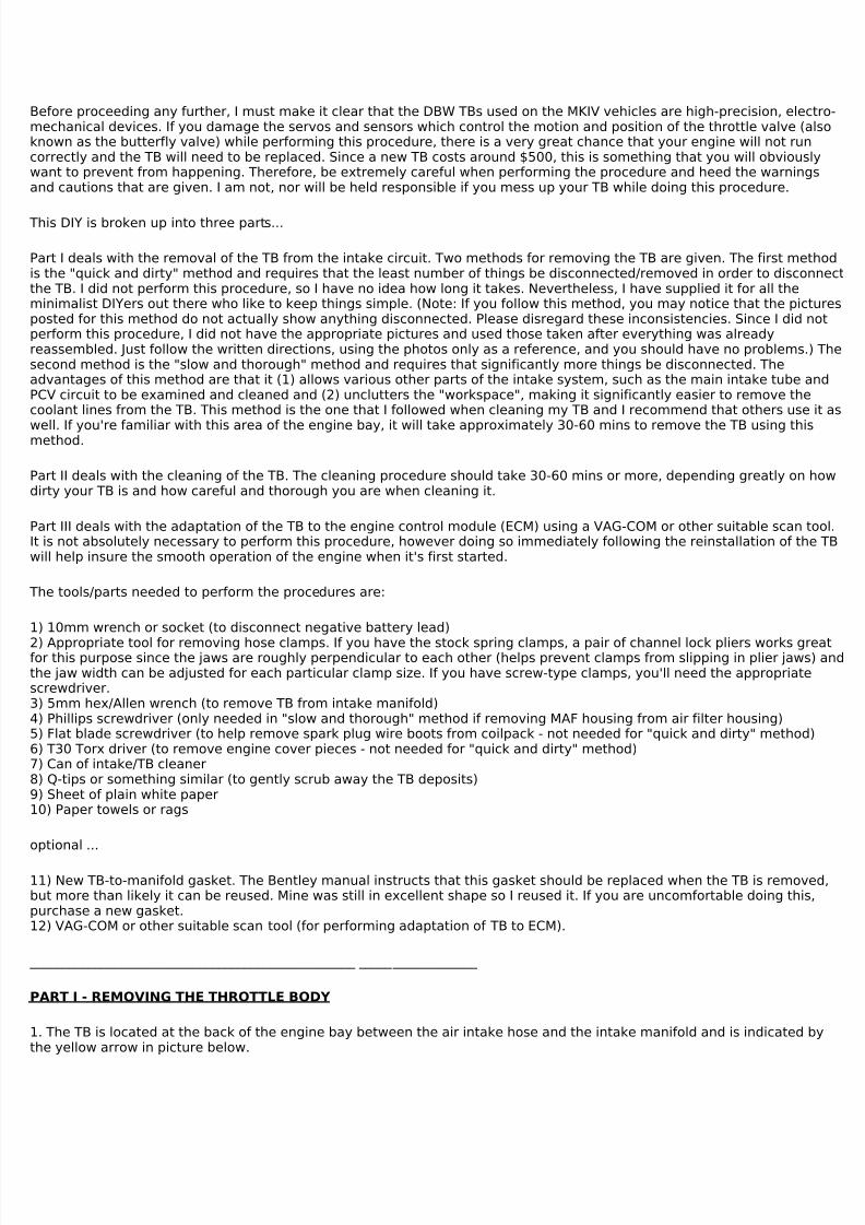
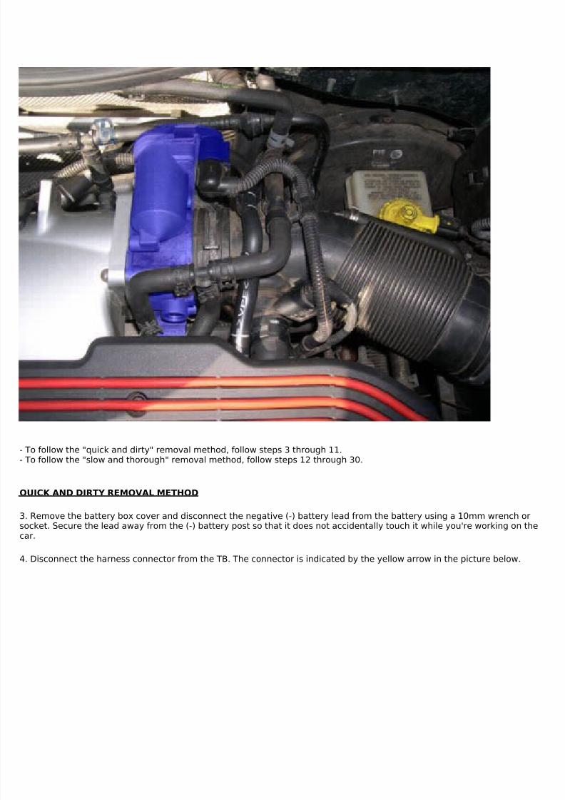
1. The TB is located at the back of the engine bay between the air intake hose and the intake manifold and is indicated bythe yellow arrow in picture below.
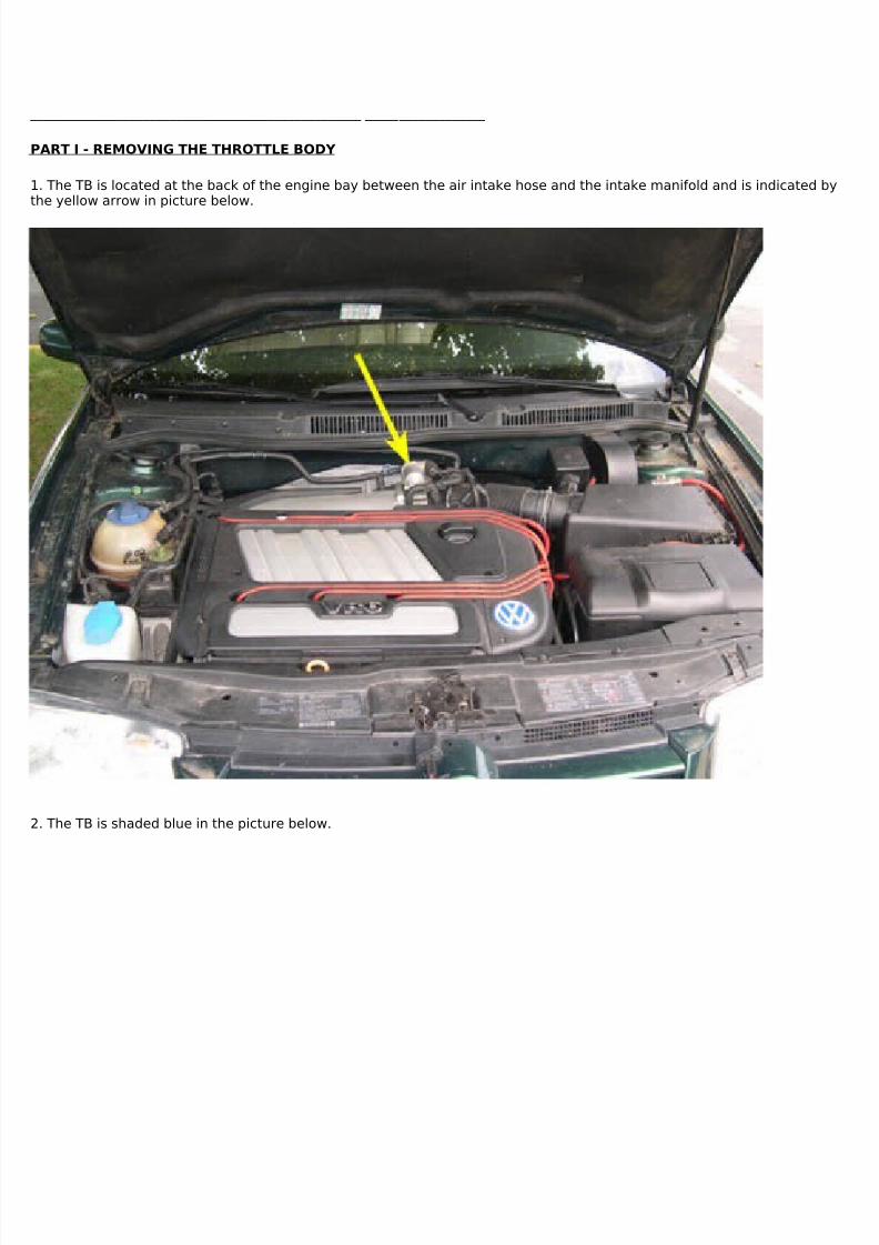
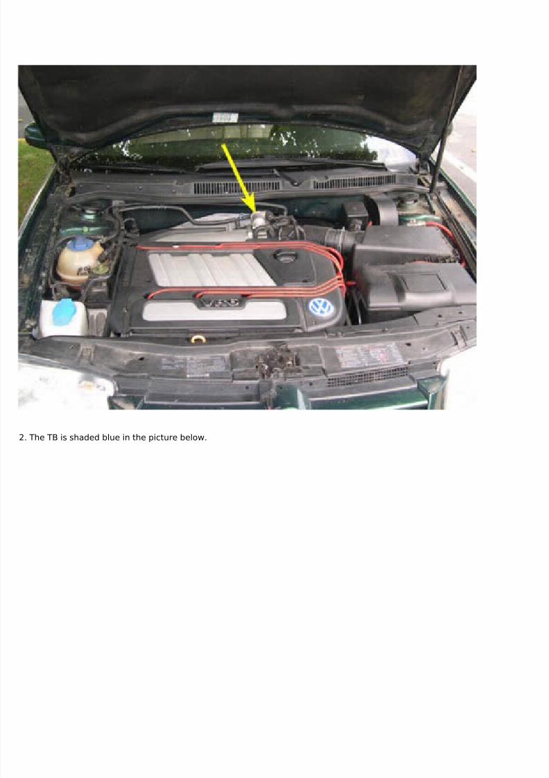
2. The TB is shaded blue in the picture below.
7/29/2019 Removing and Cleaning a Mkiv Throttle Body
- To follow the "quick and dirty" removal method, follow steps 3 through 11.- To follow the "slow and thorough" removal method, follow steps 12 through 30.
QUICK AND DIRTY REMOVAL METHOD
3. Remove the battery box cover and disconnect the negative (-) battery lead from the battery using a 10mm wrench orsocket. Secure the lead away from the (-) battery post so that it does not accidentally touch it while you're working on thecar.
4. Disconnect the harness connector from the TB. The connector is indicated by the yellow arrow in the picture below.
7/29/2019 Removing and Cleaning a Mkiv Throttle Body
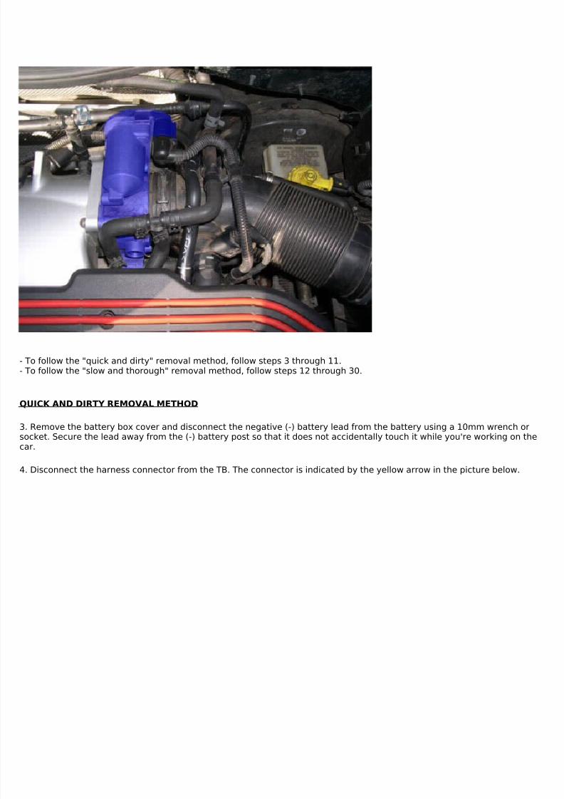
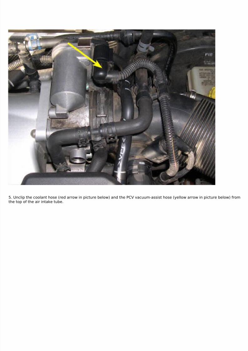
5. Unclip the coolant hose (red arrow in picture below) and the PCV vacuum-assist hose (yellow arrow in picture below) fromthe top of the air intake tube.
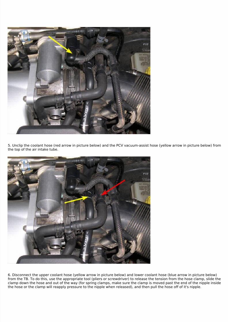
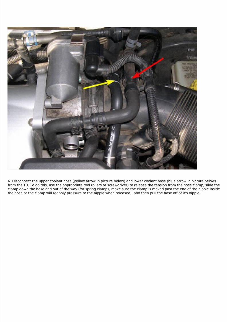
6. Disconnect the upper coolant hose (yellow arrow in picture below) and lower coolant hose (blue arrow in picture below)from the TB. To do this, use the appropriate tool (pliers or screwdriver) to release the tension from the hose clamp, slide the
clamp down the hose and out of the way (for spring clamps, make sure the clamp is moved past the end of the nipple insidethe hose or the clamp will reapply pressure to the nipple when released), and then pull the hose off of it's nipple.
7/29/2019 Removing and Cleaning a Mkiv Throttle Body
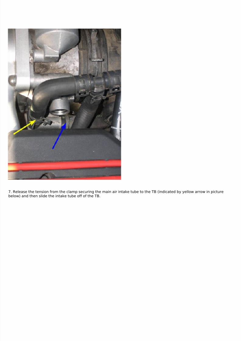
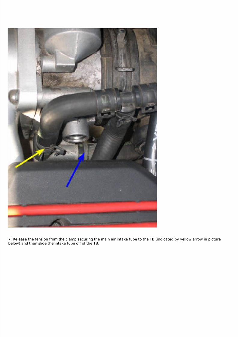
7. Release the tension from the clamp securing the main air intake tube to the TB (indicated by yellow arrow in picturebelow) and then slide the intake tube off of the TB.
7/29/2019 Removing and Cleaning a Mkiv Throttle Body
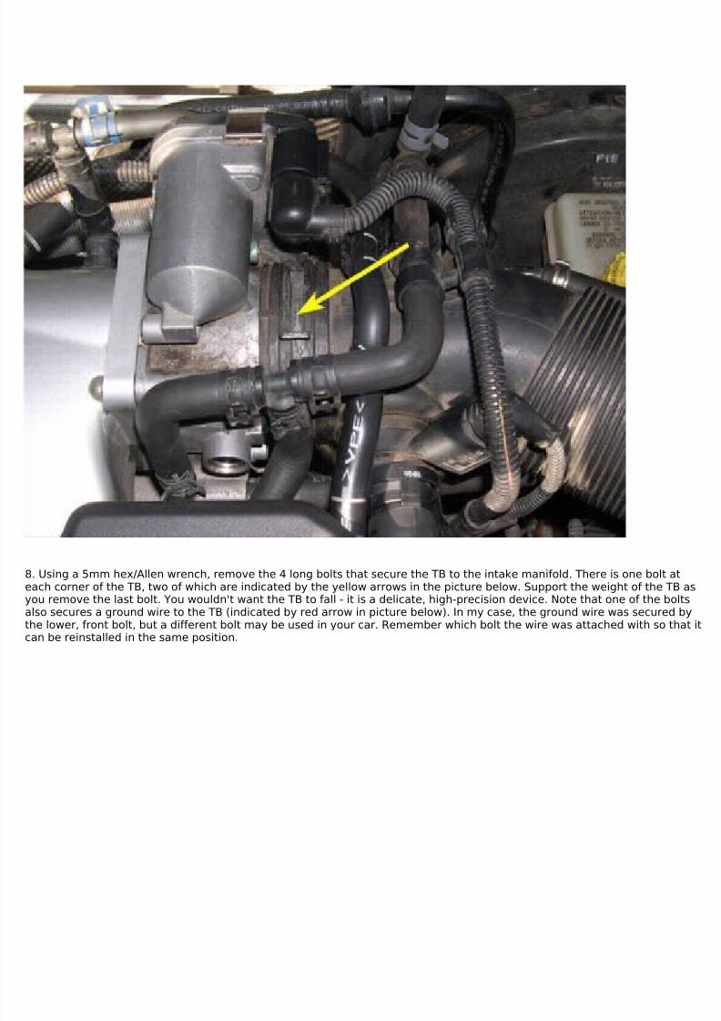
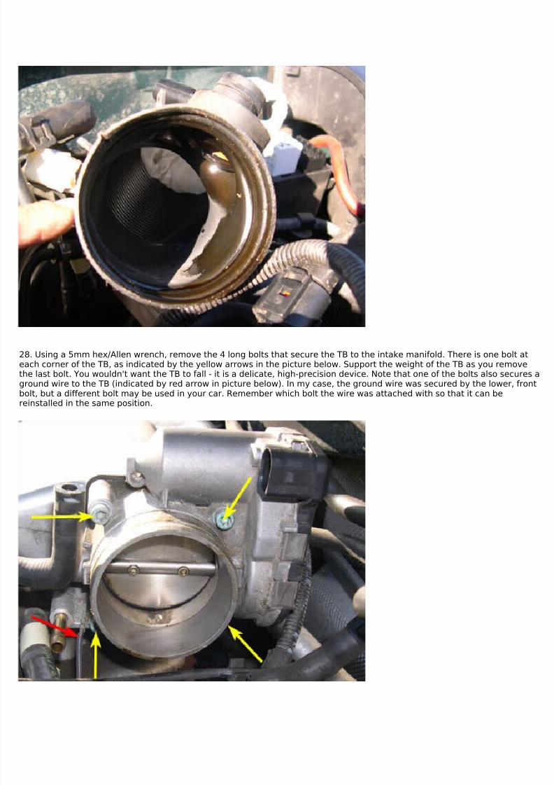
8. Using a 5mm hex/Allen wrench, remove the 4 long bolts that secure the TB to the intake manifold. There is one bolt ateach corner of the TB, two of which are indicated by the yellow arrows in the picture below. Support the weight of the TB asyou remove the last bolt. You wouldn't want the TB to fall - it is a delicate, high-precision device. Note that one of the boltsalso secures a ground wire to the TB (indicated by red arrow in picture below). In my case, the ground wire was secured bythe lower, front bolt, but a different bolt may be used in your car. Remember which bolt the wire was attached with so that itcan be reinstalled in the same position.
7/29/2019 Removing and Cleaning a Mkiv Throttle Body
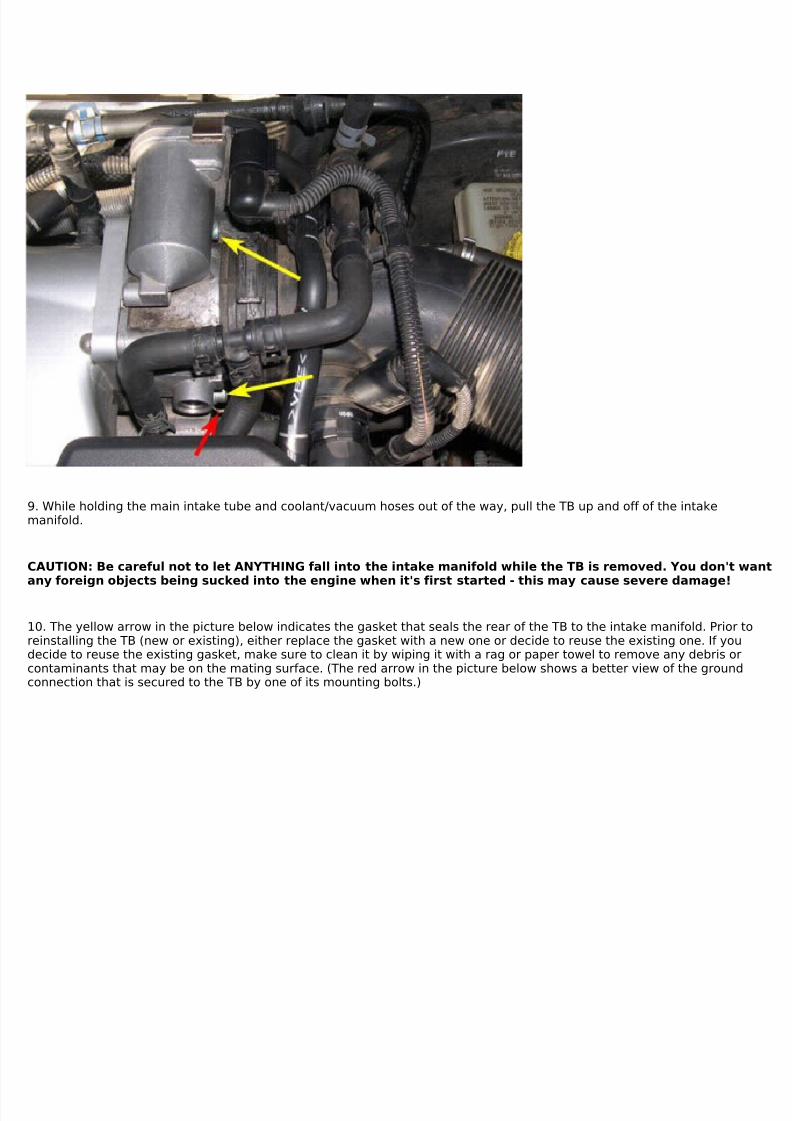
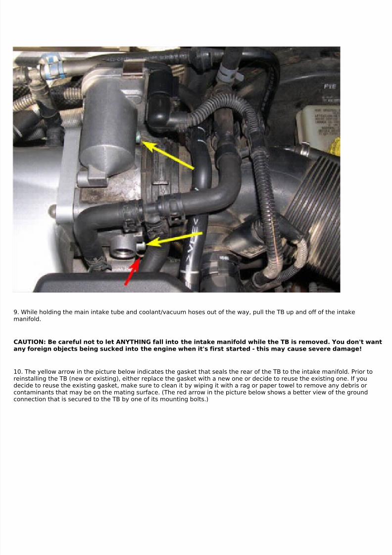
9. While holding the main intake tube and coolant/vacuum hoses out of the way, pull the TB up and off of the intakemanifold.
CAUTION: Be careful not to let ANYTHING fall into the intake manifold while the TB is removed. You don't wantany foreign objects being sucked into the engine when it's first started - this may cause severe damage!
10. The yellow arrow in the picture below indicates the gasket that seals the rear of the TB to the intake manifold. Prior toreinstalling the TB (new or existing), either replace the gasket with a new one or decide to reuse the existing one. If youdecide to reuse the existing gasket, make sure to clean it by wiping it with a rag or paper towel to remove any debris orcontaminants that may be on the mating surface. (The red arrow in the picture below shows a better view of the groundconnection that is secured to the TB by one of its mounting bolts.)
7/29/2019 Removing and Cleaning a Mkiv Throttle Body
11. If you are replacing the TB, install the new unit by following steps 3 through 9 in reverse and then proceed to Part III (TBadaptation). If you are cleaning your existing TB, proceed to Part II.
SLOW AND THOROUGH REMOVAL METHOD
12. Remove the battery box cover and disconnect the negative (-) battery lead from the battery using a 10mm wrench orsocket. Secure the lead away from the (-) battery post so that it does not accidentally touch it while you're working on thecar.
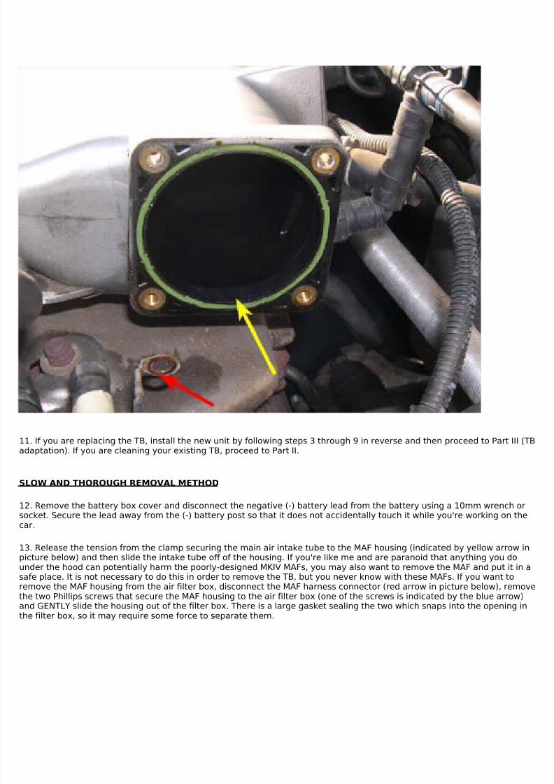
13. Release the tension from the clamp securing the main air intake tube to the MAF housing (indicated by yellow arrow inpicture below) and then slide the intake tube off of the housing. If you're like me and are paranoid that anything you dounder the hood can potentially harm the poorly-designed MKIV MAFs, you may also want to remove the MAF and put it in asafe place. It is not necessary to do this in order to remove the TB, but you never know with these MAFs. If you want toremove the MAF housing from the air filter box, disconnect the MAF harness connector (red arrow in picture below), removethe two Phillips screws that secure the MAF housing to the air filter box (one of the screws is indicated by the blue arrow)and GENTLY slide the housing out of the filter box. There is a large gasket sealing the two which snaps into the opening inthe filter box, so it may require some force to separate them.
7/29/2019 Removing and Cleaning a Mkiv Throttle Body
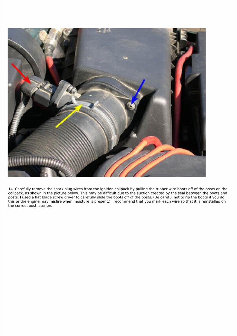
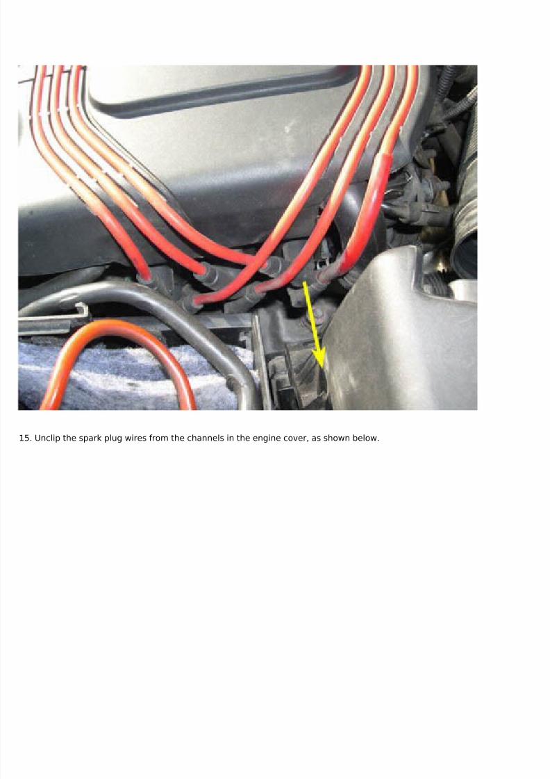
14. Carefully remove the spark plug wires from the ignition coilpack by pulling the rubber wire boots off of the posts on thecoilpack, as shown in the picture below. This may be difficult due to the suction created by the seal between the boots andposts. I used a flat blade screw driver to carefully slide the boots off of the posts. (Be careful not to rip the boots if you dothis or the engine may misfire when moisture is present.) I recommend that you mark each wire so that it is reinstalled onthe correct post later on.
7/29/2019 Removing and Cleaning a Mkiv Throttle Body
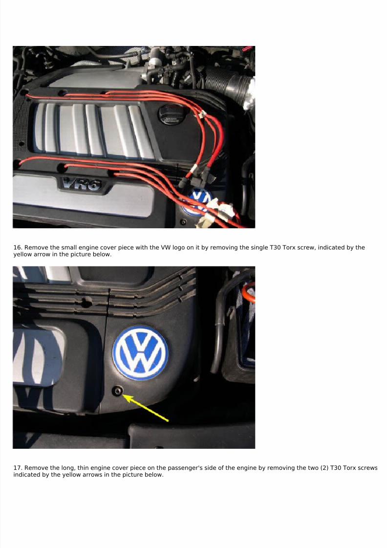
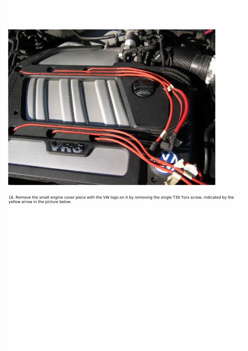
16. Remove the small engine cover piece with the VW logo on it by removing the single T30 Torx screw, indicated by theyellow arrow in the picture below.
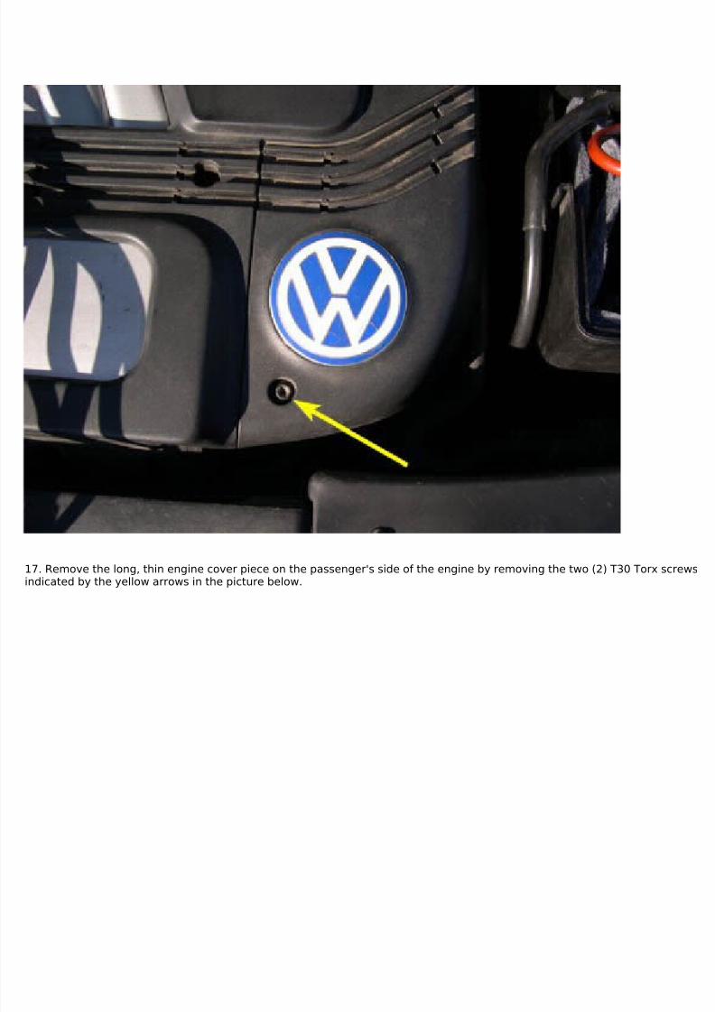
17. Remove the long, thin engine cover piece on the passenger's side of the engine by removing the two (2) T30 Torx screwsindicated by the yellow arrows in the picture below.
7/29/2019 Removing and Cleaning a Mkiv Throttle Body
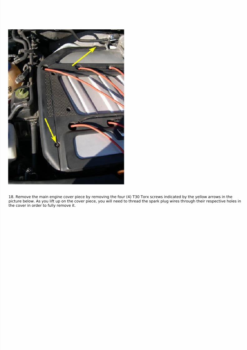
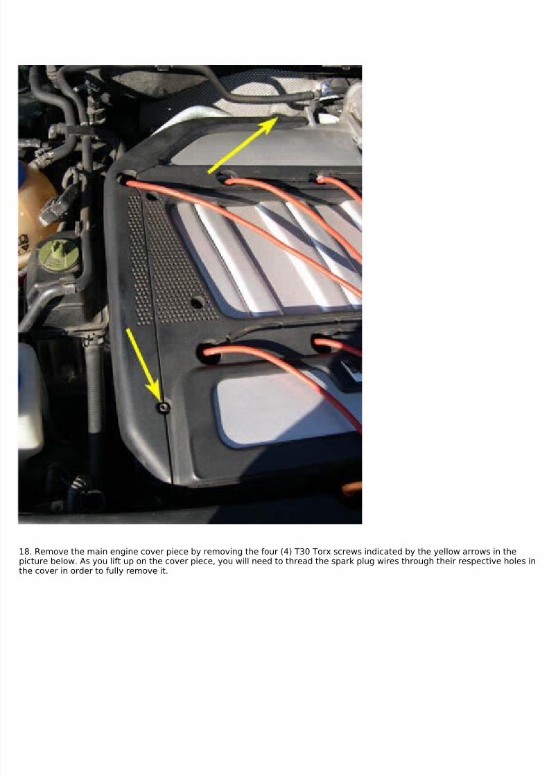
18. Remove the main engine cover piece by removing the four (4) T30 Torx screws indicated by the yellow arrows in thepicture below. As you lift up on the cover piece, you will need to thread the spark plug wires through their respective holes inthe cover in order to fully remove it.
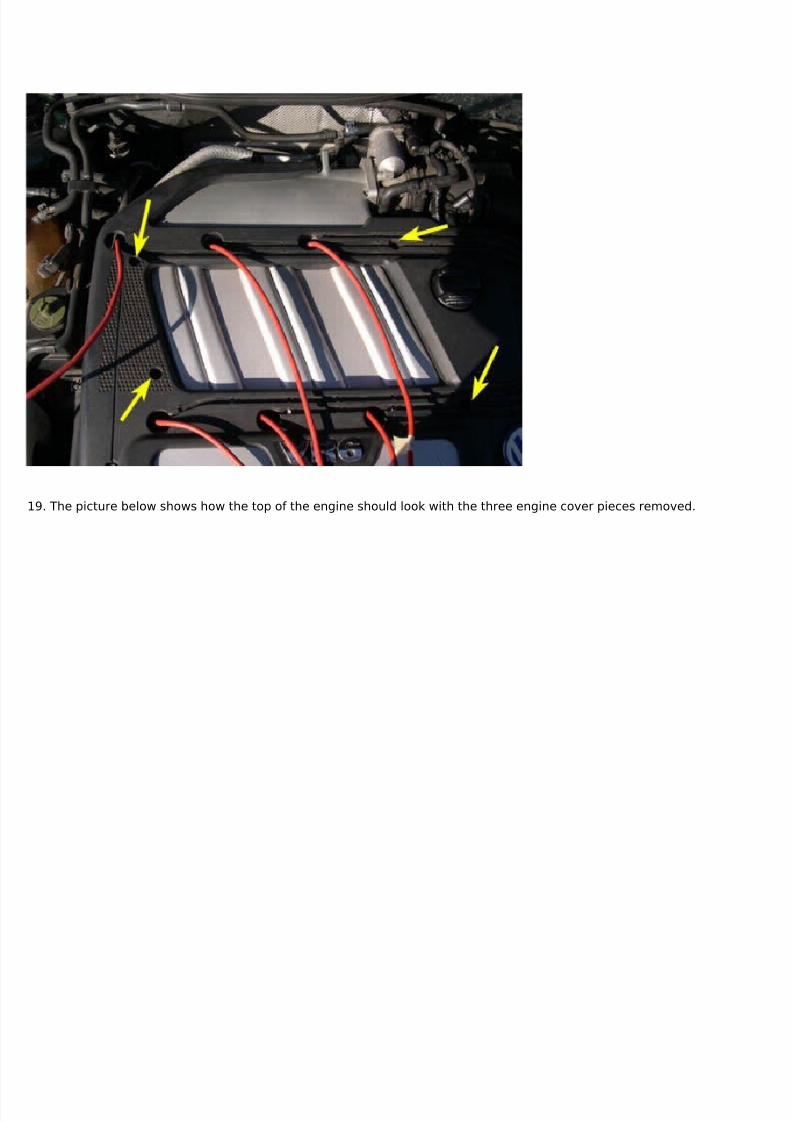
7/29/2019 Removing and Cleaning a Mkiv Throttle Body
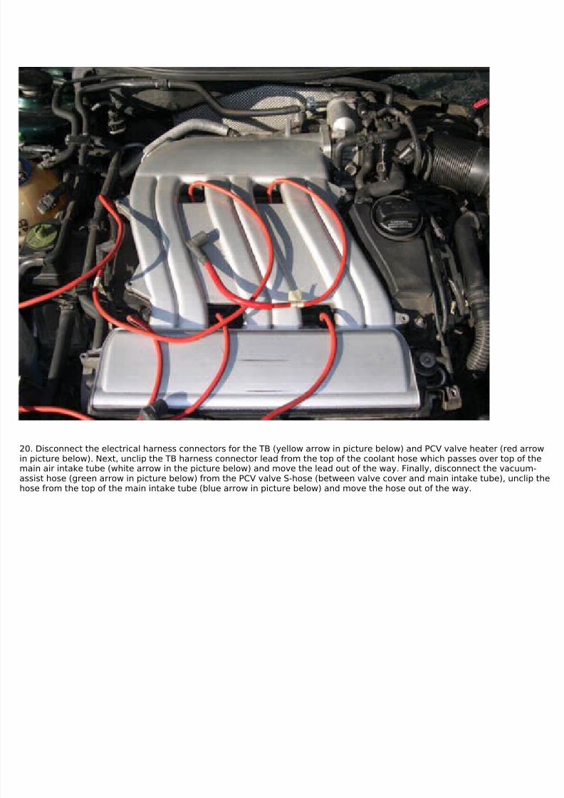
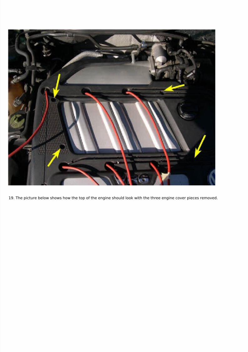
20. Disconnect the electrical harness connectors for the TB (yellow arrow in picture below) and PCV valve heater (red arrowin picture below). Next, unclip the TB harness connector lead from the top of the coolant hose which passes over top of themain air intake tube (white arrow in the picture below) and move the lead out of the way. Finally, disconnect the vacuum-assist hose (green arrow in picture below) from the PCV valve S-hose (between valve cover and main intake tube), unclip thehose from the top of the main intake tube (blue arrow in picture below) and move the hose out of the way.
7/29/2019 Removing and Cleaning a Mkiv Throttle Body
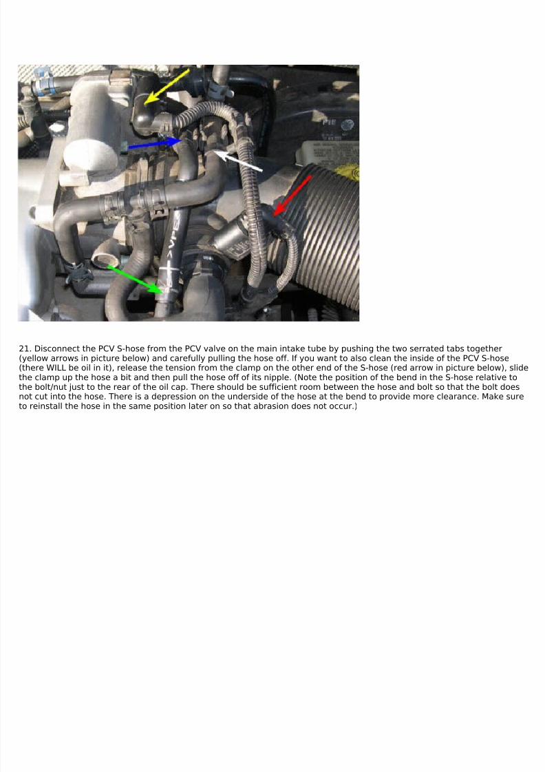
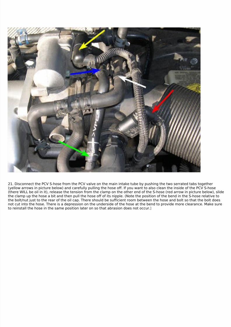
21. Disconnect the PCV S-hose from the PCV valve on the main intake tube by pushing the two serrated tabs together(yellow arrows in picture below) and carefully pulling the hose off. If you want to also clean the inside of the PCV S-hose(there WILL be oil in it), release the tension from the clamp on the other end of the S-hose (red arrow in picture below), slidethe clamp up the hose a bit and then pull the hose off of its nipple. (Note the position of the bend in the S-hose relative tothe bolt/nut just to the rear of the oil cap. There should be sufficient room between the hose and bolt so that the bolt doesnot cut into the hose. There is a depression on the underside of the hose at the bend to provide more clearance. Make sure
to reinstall the hose in the same position later on so that abrasion does not occur.)
7/29/2019 Removing and Cleaning a Mkiv Throttle Body
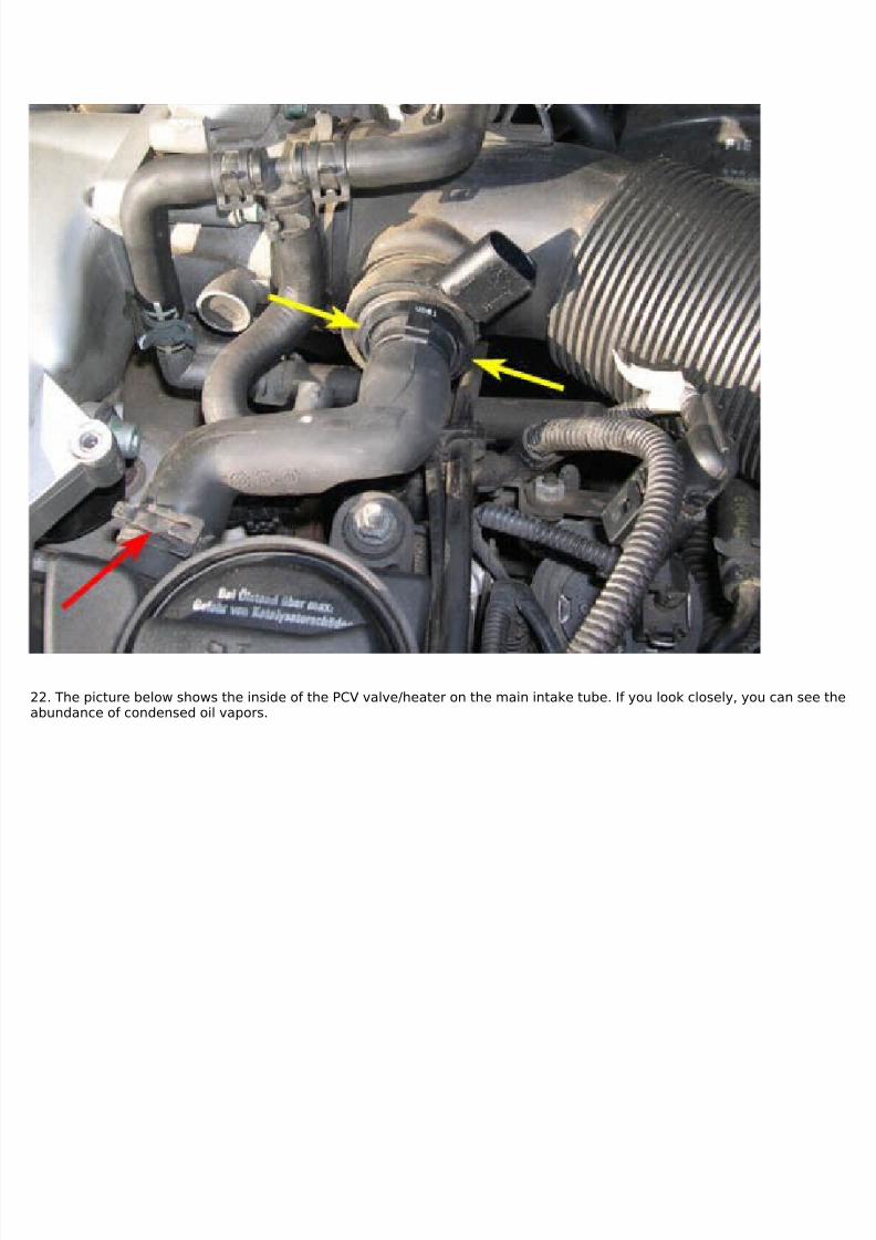
22. The picture below shows the inside of the PCV valve/heater on the main intake tube. If you look closely, you can see theabundance of condensed oil vapors.
7/29/2019 Removing and Cleaning a Mkiv Throttle Body
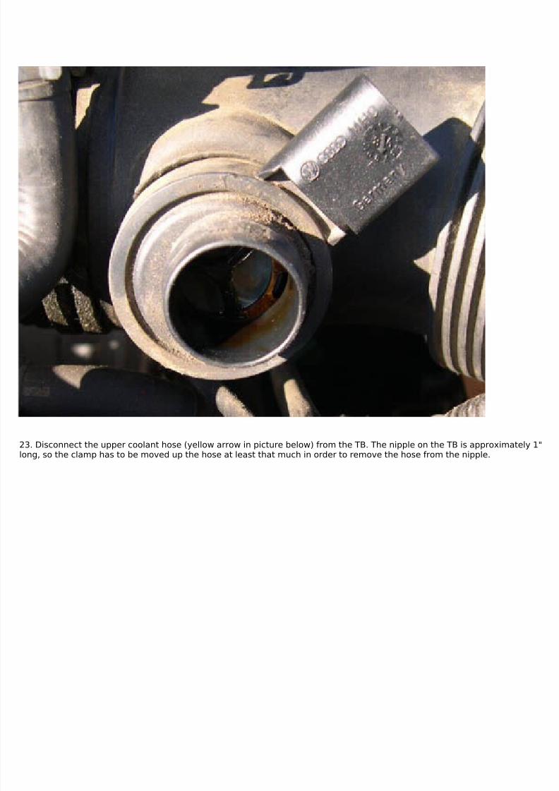
23. Disconnect the upper coolant hose (yellow arrow in picture below) from the TB. The nipple on the TB is approximately 1"long, so the clamp has to be moved up the hose at least that much in order to remove the hose from the nipple.
7/29/2019 Removing and Cleaning a Mkiv Throttle Body
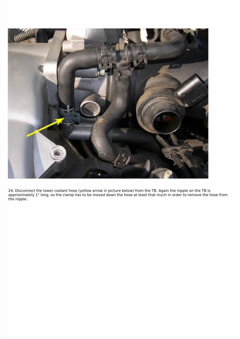
24. Disconnect the lower coolant hose (yellow arrow in picture below) from the TB. Again the nipple on the TB isapproximately 1" long, so the clamp has to be moved down the hose at least that much in order to remove the hose fromthe nipple.
7/29/2019 Removing and Cleaning a Mkiv Throttle Body
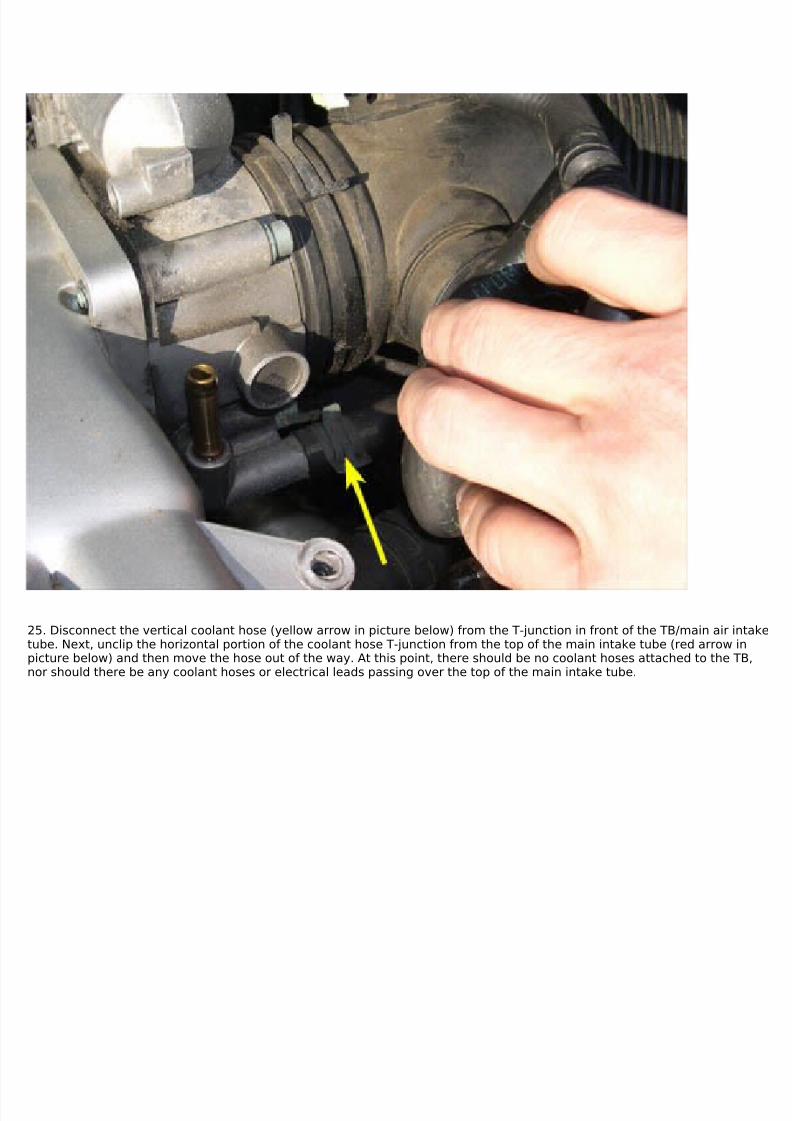
25. Disconnect the vertical coolant hose (yellow arrow in picture below) from the T-junction in front of the TB/main air intaketube. Next, unclip the horizontal portion of the coolant hose T-junction from the top of the main intake tube (red arrow inpicture below) and then move the hose out of the way. At this point, there should be no coolant hoses attached to the TB,nor should there be any coolant hoses or electrical leads passing over the top of the main intake tube.
7/29/2019 Removing and Cleaning a Mkiv Throttle Body
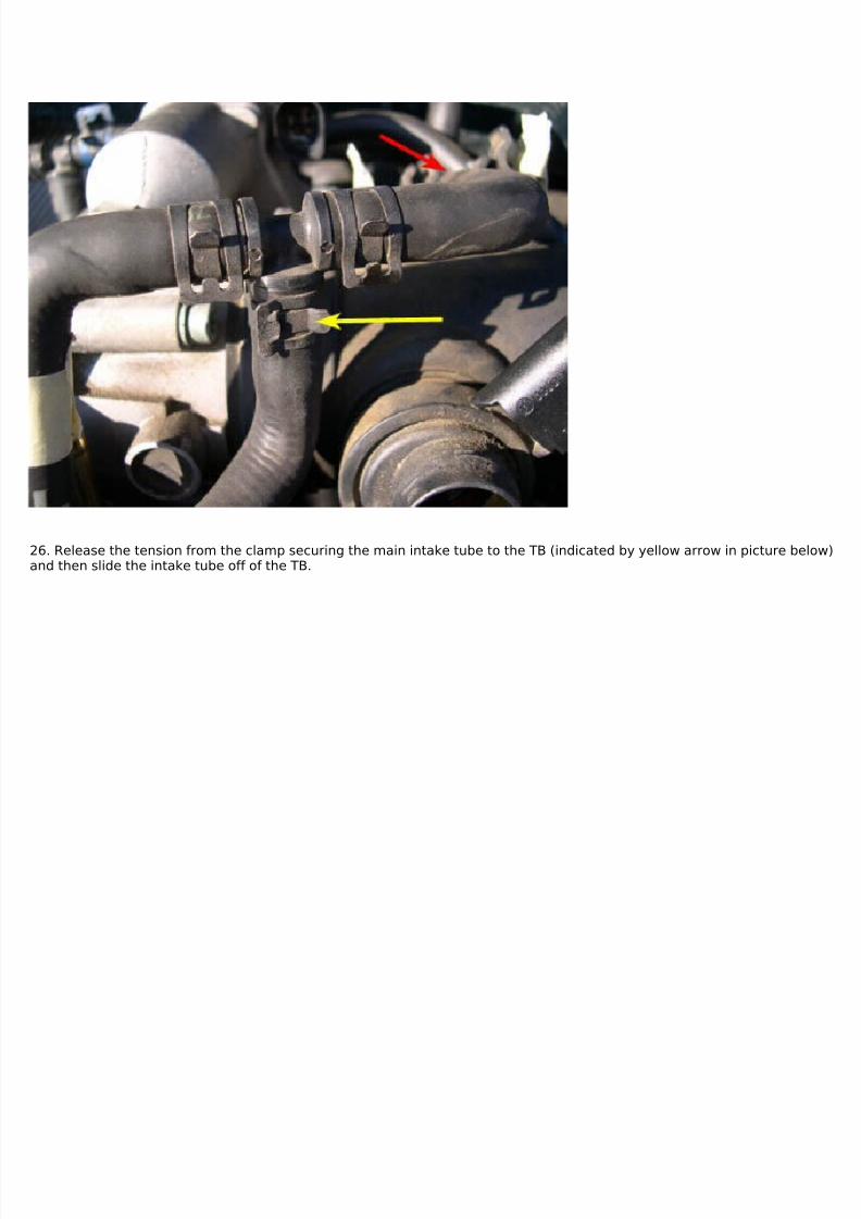
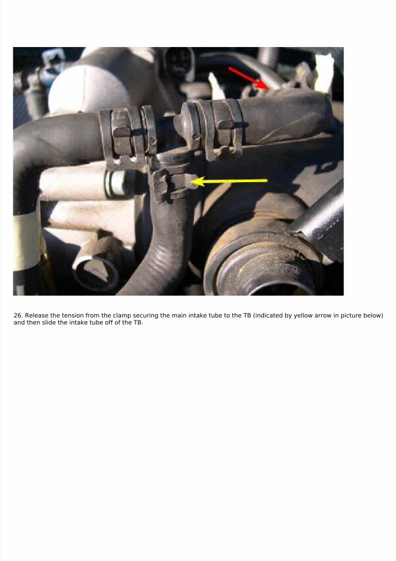
26. Release the tension from the clamp securing the main intake tube to the TB (indicated by yellow arrow in picture below)and then slide the intake tube off of the TB.
7/29/2019 Removing and Cleaning a Mkiv Throttle Body
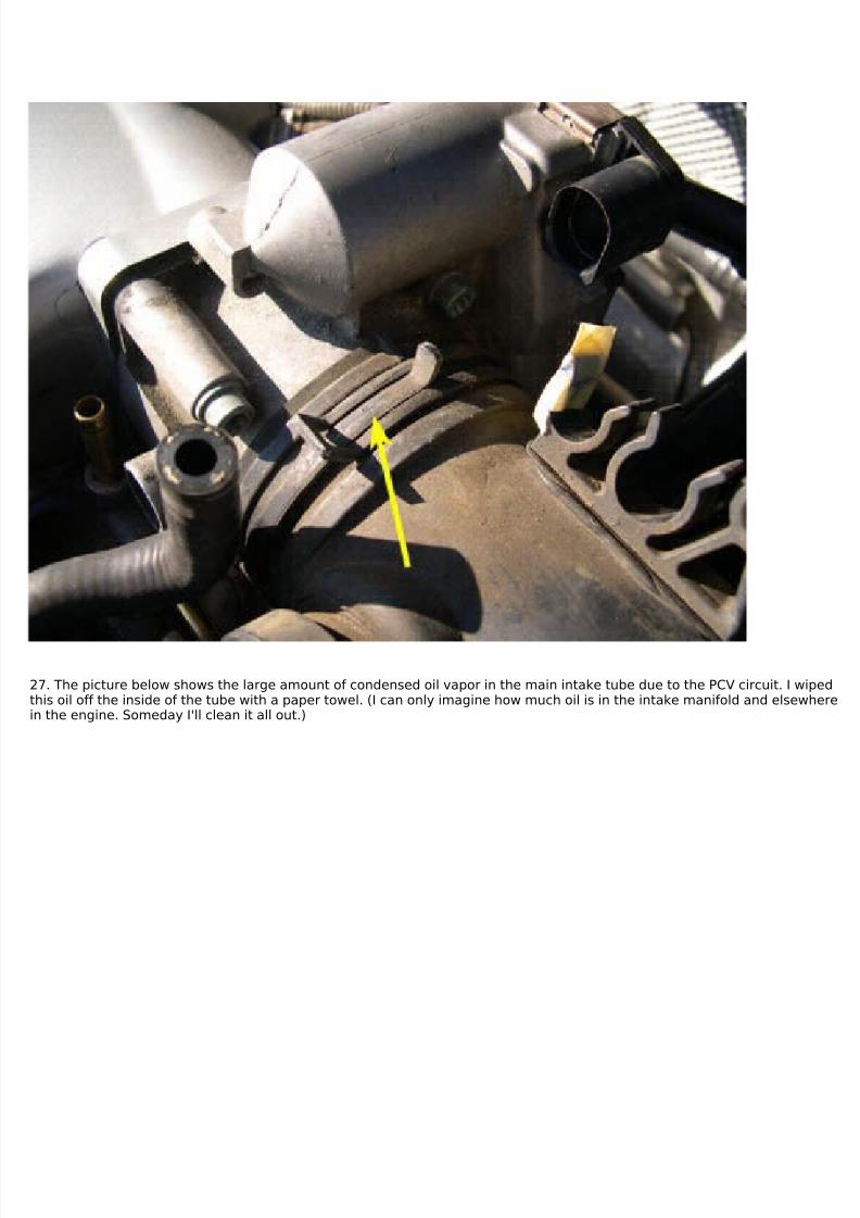
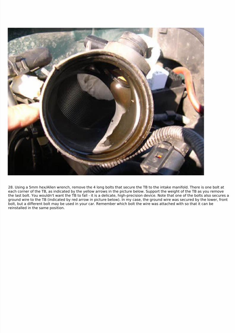
27. The picture below shows the large amount of condensed oil vapor in the main intake tube due to the PCV circuit. I wipedthis oil off the inside of the tube with a paper towel. (I can only imagine how much oil is in the intake manifold and elsewherein the engine. Someday I'll clean it all out.)
7/29/2019 Removing and Cleaning a Mkiv Throttle Body
28. Using a 5mm hex/Allen wrench, remove the 4 long bolts that secure the TB to the intake manifold. There is one bolt ateach corner of the TB, as indicated by the yellow arrows in the picture below. Support the weight of the TB as you removethe last bolt. You wouldn't want the TB to fall - it is a delicate, high-precision device. Note that one of the bolts also secures aground wire to the TB (indicated by red arrow in picture below). In my case, the ground wire was secured by the lower, frontbolt, but a different bolt may be used in your car. Remember which bolt the wire was attached with so that it can bereinstalled in the same position.
7/29/2019 Removing and Cleaning a Mkiv Throttle Body
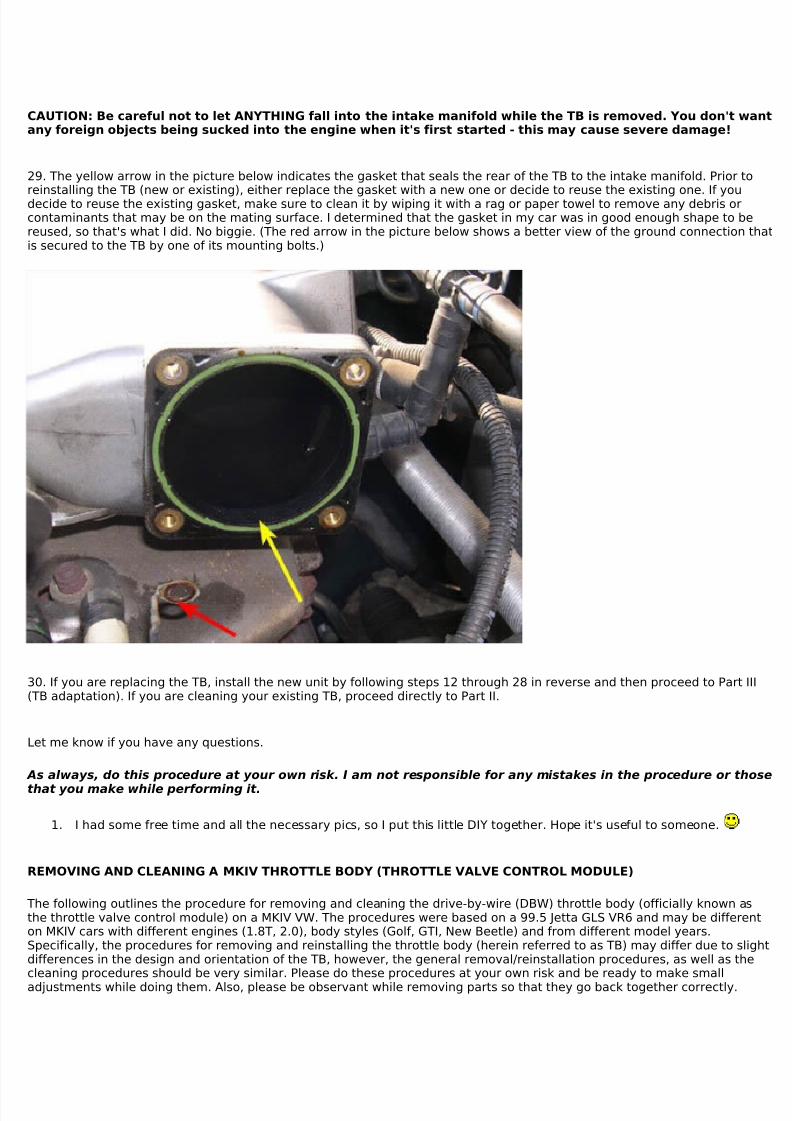
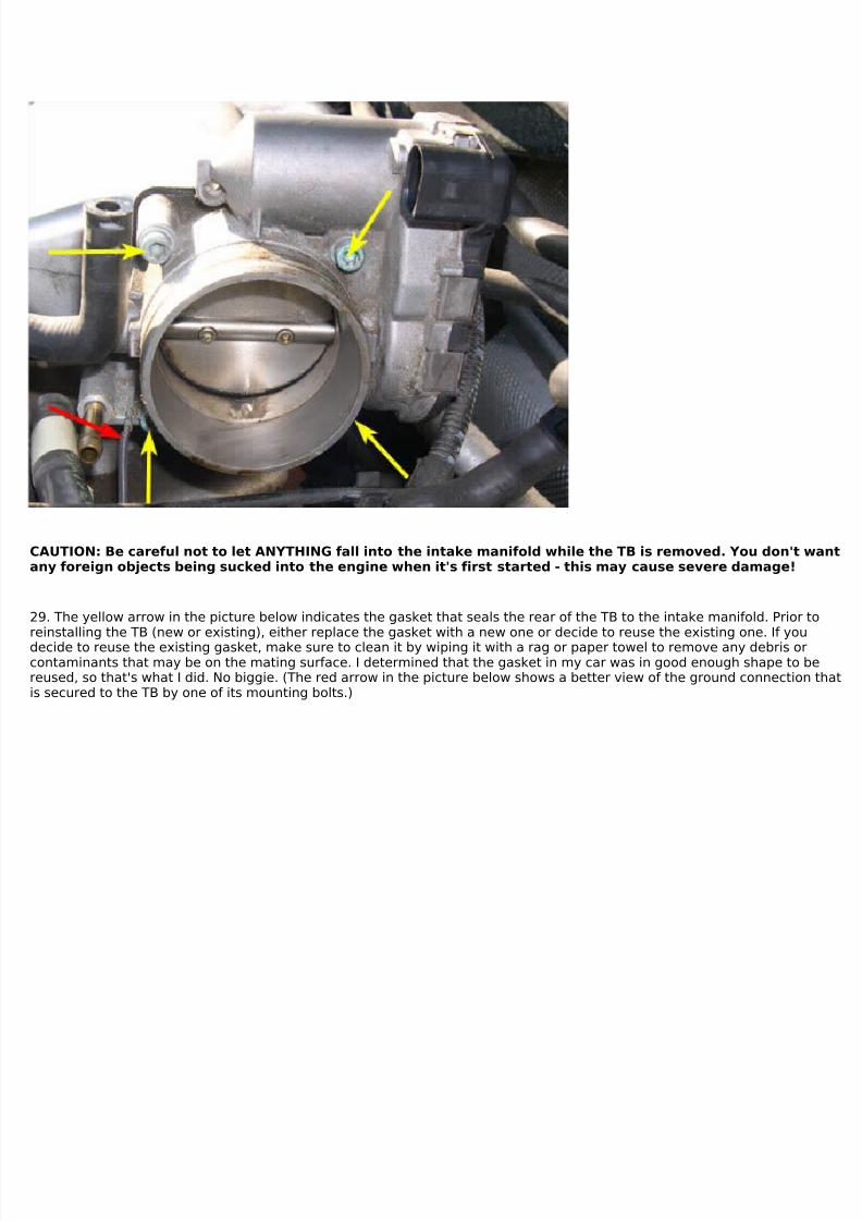
CAUTION: Be careful not to let ANYTHING fall into the intake manifold while the TB is removed. You don't wantany foreign objects being sucked into the engine when it's first started - this may cause severe damage!
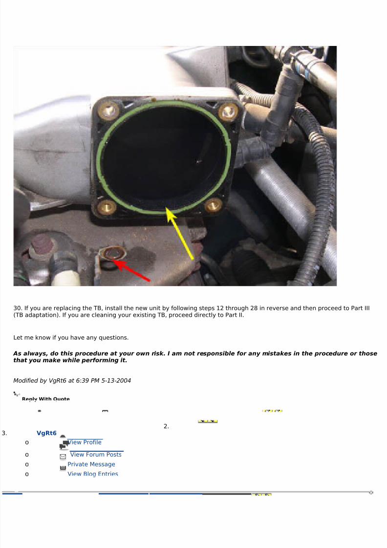
29. The yellow arrow in the picture below indicates the gasket that seals the rear of the TB to the intake manifold. Prior to
reinstalling the TB (new or existing), either replace the gasket with a new one or decide to reuse the existing one. If youdecide to reuse the existing gasket, make sure to clean it by wiping it with a rag or paper towel to remove any debris orcontaminants that may be on the mating surface. I determined that the gasket in my car was in good enough shape to bereused, so that's what I did. No biggie. (The red arrow in the picture below shows a better view of the ground connection thatis secured to the TB by one of its mounting bolts.)
30. If you are replacing the TB, install the new unit by following steps 12 through 28 in reverse and then proceed to Part III(TB adaptation). If you are cleaning your existing TB, proceed directly to Part II.
Let me know if you have any questions.
As always, do this procedure at your own risk. I am not responsible for any mistakes in the procedure or those
that you make while performing it.
1. I had some free time and all the necessary pics, so I put this little DIY together. Hope it's useful to someone.
REMOVING AND CLEANING A MKIV THROTTLE BODY (THROTTLE VALVE CONTROL MODULE)
The following outlines the procedure for removing and cleaning the drive-by-wire (DBW) throttle body (officially known asthe throttle valve control module) on a MKIV VW. The procedures were based on a 99.5 Jetta GLS VR6 and may be differenton MKIV cars with different engines (1.8T, 2.0), body styles (Golf, GTI, New Beetle) and from different model years.Specifically, the procedures for removing and reinstalling the throttle body (herein referred to as TB) may differ due to slightdifferences in the design and orientation of the TB, however, the general removal/reinstallation procedures, as well as thecleaning procedures should be very similar. Please do these procedures at your own risk and be ready to make smalladjustments while doing them. Also, please be observant while removing parts so that they go back together correctly.
7/29/2019 Removing and Cleaning a Mkiv Throttle Body
Before proceeding any further, I must make it clear that the DBW TBs used on the MKIV vehicles are high-precision, electro-mechanical devices. If you damage the servos and sensors which control the motion and position of the throttle valve (alsoknown as the butterfly valve) while performing this procedure, there is a very great chance that your engine will not runcorrectly and the TB will need to be replaced. Since a new TB costs around $500, this is something that you will obviouslywant to prevent from happening. Therefore, be extremely careful when performing the procedure and heed the warningsand cautions that are given. I am not, nor will be held responsible if you mess up your TB while doing this procedure.
This DIY is broken up into three parts...
Part I deals with the removal of the TB from the intake circuit. Two methods for removing the TB are given. The first methodis the "quick and dirty" method and requires that the least number of things be disconnected/removed in order to disconnectthe TB. I did not perform this procedure, so I have no idea how long it takes. Nevertheless, I have supplied it for all theminimalist DIYers out there who like to keep things simple. (Note: If you follow this method, you may notice that the picturesposted for this method do not actually show anything disconnected. Please disregard these inconsistencies. Since I did notperform this procedure, I did not have the appropriate pictures and used those taken after everything was alreadyreassembled. Just follow the written directions, using the photos only as a reference, and you should have no problems.) Thesecond method is the "slow and thorough" method and requires that significantly more things be disconnected. Theadvantages of this method are that it (1) allows various other parts of the intake system, such as the main intake tube andPCV circuit to be examined and cleaned and (2) unclutters the "workspace", making it significantly easier to remove thecoolant lines from the TB. This method is the one that I followed when cleaning my TB and I recommend that others use it as
well. If you're familiar with this area of the engine bay, it will take approximately 30-60 mins to remove the TB using thismethod.
Part II deals with the cleaning of the TB. The cleaning procedure should take 30-60 mins or more, depending greatly on howdirty your TB is and how careful and thorough you are when cleaning it.
Part III deals with the adaptation of the TB to the engine control module (ECM) using a VAG-COM or other suitable scan tool.It is not absolutely necessary to perform this procedure, however doing so immediately following the reinstallation of the TBwill help insure the smooth operation of the engine when it's first started.
The tools/parts needed to perform the procedures are:
1) 10mm wrench or socket (to disconnect negative battery lead)
2) Appropriate tool for removing hose clamps. If you have the stock spring clamps, a pair of channel lock pliers works greatfor this purpose since the jaws are roughly perpendicular to each other (helps prevent clamps from slipping in plier jaws) andthe jaw width can be adjusted for each particular clamp size. If you have screw-type clamps, you'll need the appropriatescrewdriver.3) 5mm hex/Allen wrench (to remove TB from intake manifold)4) Phillips screwdriver (only needed in "slow and thorough" method if removing MAF housing from air filter housing)5) Flat blade screwdriver (to help remove spark plug wire boots from coilpack - not needed for "quick and dirty" method)6) T30 Torx driver (to remove engine cover pieces - not needed for "quick and dirty" method)7) Can of intake/TB cleaner8) Q-tips or something similar (to gently scrub away the TB deposits)9) Sheet of plain white paper10) Paper towels or rags
optional ...
11) New TB-to-manifold gasket. The Bentley manual instructs that this gasket should be replaced when the TB is removed,but more than likely it can be reused. Mine was still in excellent shape so I reused it. If you are uncomfortable doing this,purchase a new gasket.12) VAG-COM or other suitable scan tool (for performing adaptation of TB to ECM).
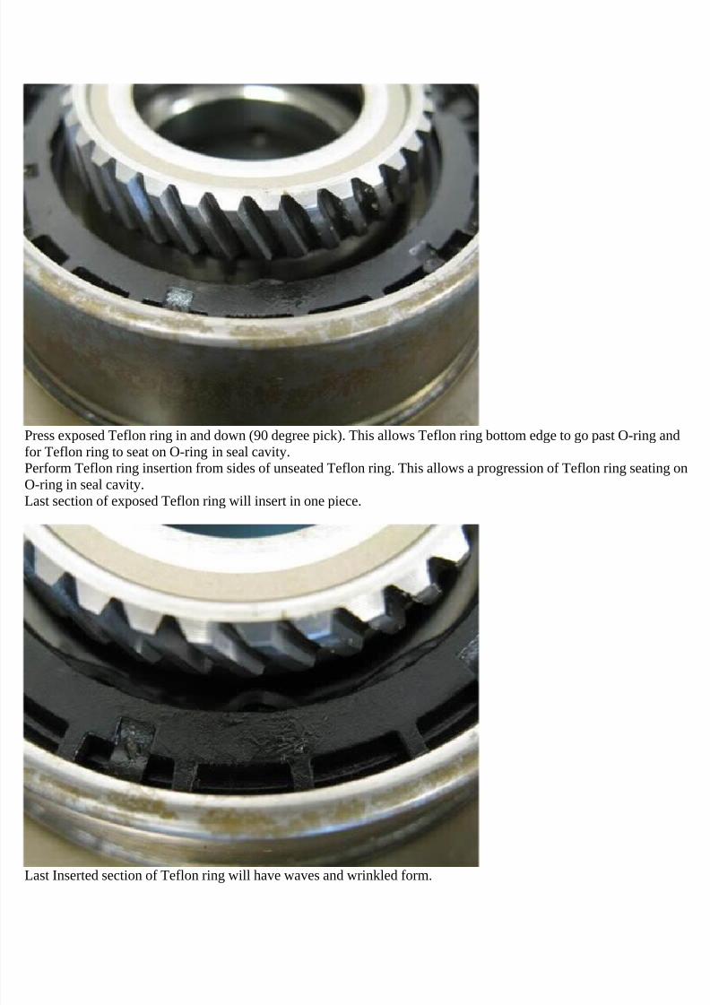
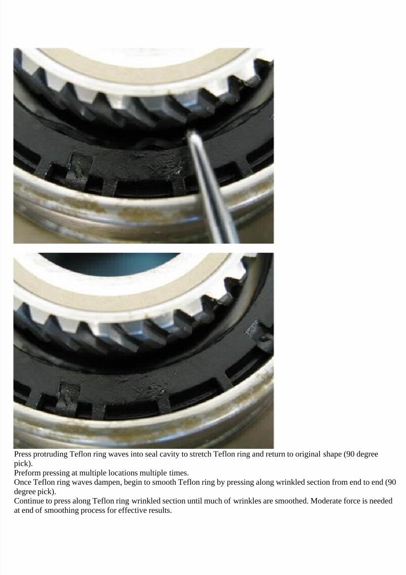
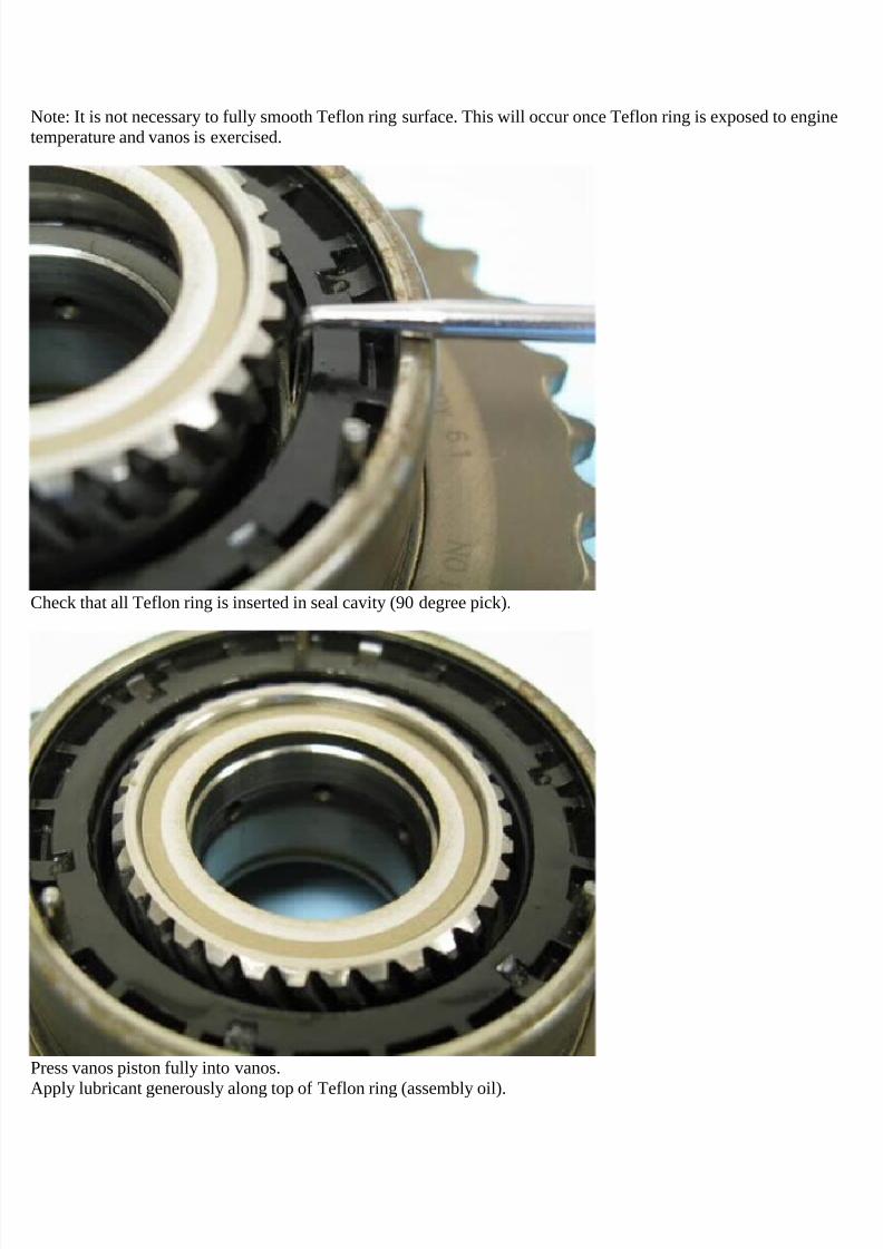
1. The TB is located at the back of the engine bay between the air intake hose and the intake manifold and is indicated bythe yellow arrow in picture below.
7/29/2019 Removing and Cleaning a Mkiv Throttle Body
- To follow the "quick and dirty" removal method, follow steps 3 through 11.- To follow the "slow and thorough" removal method, follow steps 12 through 30.
QUICK AND DIRTY REMOVAL METHOD
3. Remove the battery box cover and disconnect the negative (-) battery lead from the battery using a 10mm wrench orsocket. Secure the lead away from the (-) battery post so that it does not accidentally touch it while you're working on thecar.
4. Disconnect the harness connector from the TB. The connector is indicated by the yellow arrow in the picture below.
7/29/2019 Removing and Cleaning a Mkiv Throttle Body
5. Unclip the coolant hose (red arrow in picture below) and the PCV vacuum-assist hose (yellow arrow in picture below) fromthe top of the air intake tube.
7/29/2019 Removing and Cleaning a Mkiv Throttle Body
6. Disconnect the upper coolant hose (yellow arrow in picture below) and lower coolant hose (blue arrow in picture below)from the TB. To do this, use the appropriate tool (pliers or screwdriver) to release the tension from the hose clamp, slide theclamp down the hose and out of the way (for spring clamps, make sure the clamp is moved past the end of the nipple insidethe hose or the clamp will reapply pressure to the nipple when released), and then pull the hose off of it's nipple.
7/29/2019 Removing and Cleaning a Mkiv Throttle Body
7. Release the tension from the clamp securing the main air intake tube to the TB (indicated by yellow arrow in picturebelow) and then slide the intake tube off of the TB.
7/29/2019 Removing and Cleaning a Mkiv Throttle Body
8. Using a 5mm hex/Allen wrench, remove the 4 long bolts that secure the TB to the intake manifold. There is one bolt ateach corner of the TB, two of which are indicated by the yellow arrows in the picture below. Support the weight of the TB asyou remove the last bolt. You wouldn't want the TB to fall - it is a delicate, high-precision device. Note that one of the boltsalso secures a ground wire to the TB (indicated by red arrow in picture below). In my case, the ground wire was secured bythe lower, front bolt, but a different bolt may be used in your car. Remember which bolt the wire was attached with so that itcan be reinstalled in the same position.
7/29/2019 Removing and Cleaning a Mkiv Throttle Body
9. While holding the main intake tube and coolant/vacuum hoses out of the way, pull the TB up and off of the intakemanifold.
CAUTION: Be careful not to let ANYTHING fall into the intake manifold while the TB is removed. You don't wantany foreign objects being sucked into the engine when it's first started - this may cause severe damage!
10. The yellow arrow in the picture below indicates the gasket that seals the rear of the TB to the intake manifold. Prior toreinstalling the TB (new or existing), either replace the gasket with a new one or decide to reuse the existing one. If youdecide to reuse the existing gasket, make sure to clean it by wiping it with a rag or paper towel to remove any debris orcontaminants that may be on the mating surface. (The red arrow in the picture below shows a better view of the groundconnection that is secured to the TB by one of its mounting bolts.)
7/29/2019 Removing and Cleaning a Mkiv Throttle Body
11. If you are replacing the TB, install the new unit by following steps 3 through 9 in reverse and then proceed to Part III (TBadaptation). If you are cleaning your existing TB, proceed to Part II.
SLOW AND THOROUGH REMOVAL METHOD
12. Remove the battery box cover and disconnect the negative (-) battery lead from the battery using a 10mm wrench orsocket. Secure the lead away from the (-) battery post so that it does not accidentally touch it while you're working on thecar.
13. Release the tension from the clamp securing the main air intake tube to the MAF housing (indicated by yellow arrow inpicture below) and then slide the intake tube off of the housing. If you're like me and are paranoid that anything you dounder the hood can potentially harm the poorly-designed MKIV MAFs, you may also want to remove the MAF and put it in asafe place. It is not necessary to do this in order to remove the TB, but you never know with these MAFs. If you want toremove the MAF housing from the air filter box, disconnect the MAF harness connector (red arrow in picture below), removethe two Phillips screws that secure the MAF housing to the air filter box (one of the screws is indicated by the blue arrow)and GENTLY slide the housing out of the filter box. There is a large gasket sealing the two which snaps into the opening inthe filter box, so it may require some force to separate them.
7/29/2019 Removing and Cleaning a Mkiv Throttle Body
14. Carefully remove the spark plug wires from the ignition coilpack by pulling the rubber wire boots off of the posts on thecoilpack, as shown in the picture below. This may be difficult due to the suction created by the seal between the boots andposts. I used a flat blade screw driver to carefully slide the boots off of the posts. (Be careful not to rip the boots if you dothis or the engine may misfire when moisture is present.) I recommend that you mark each wire so that it is reinstalled onthe correct post later on.
7/29/2019 Removing and Cleaning a Mkiv Throttle Body
16. Remove the small engine cover piece with the VW logo on it by removing the single T30 Torx screw, indicated by theyellow arrow in the picture below.
7/29/2019 Removing and Cleaning a Mkiv Throttle Body
17. Remove the long, thin engine cover piece on the passenger's side of the engine by removing the two (2) T30 Torx screwsindicated by the yellow arrows in the picture below.
7/29/2019 Removing and Cleaning a Mkiv Throttle Body
18. Remove the main engine cover piece by removing the four (4) T30 Torx screws indicated by the yellow arrows in thepicture below. As you lift up on the cover piece, you will need to thread the spark plug wires through their respective holes inthe cover in order to fully remove it.
7/29/2019 Removing and Cleaning a Mkiv Throttle Body
20. Disconnect the electrical harness connectors for the TB (yellow arrow in picture below) and PCV valve heater (red arrowin picture below). Next, unclip the TB harness connector lead from the top of the coolant hose which passes over top of themain air intake tube (white arrow in the picture below) and move the lead out of the way. Finally, disconnect the vacuum-assist hose (green arrow in picture below) from the PCV valve S-hose (between valve cover and main intake tube), unclip thehose from the top of the main intake tube (blue arrow in picture below) and move the hose out of the way.
7/29/2019 Removing and Cleaning a Mkiv Throttle Body
21. Disconnect the PCV S-hose from the PCV valve on the main intake tube by pushing the two serrated tabs together(yellow arrows in picture below) and carefully pulling the hose off. If you want to also clean the inside of the PCV S-hose(there WILL be oil in it), release the tension from the clamp on the other end of the S-hose (red arrow in picture below), slidethe clamp up the hose a bit and then pull the hose off of its nipple. (Note the position of the bend in the S-hose relative tothe bolt/nut just to the rear of the oil cap. There should be sufficient room between the hose and bolt so that the bolt doesnot cut into the hose. There is a depression on the underside of the hose at the bend to provide more clearance. Make sureto reinstall the hose in the same position later on so that abrasion does not occur.)
7/29/2019 Removing and Cleaning a Mkiv Throttle Body
22. The picture below shows the inside of the PCV valve/heater on the main intake tube. If you look closely, you can see theabundance of condensed oil vapors.
7/29/2019 Removing and Cleaning a Mkiv Throttle Body
23. Disconnect the upper coolant hose (yellow arrow in picture below) from the TB. The nipple on the TB is approximately 1"long, so the clamp has to be moved up the hose at least that much in order to remove the hose from the nipple.
7/29/2019 Removing and Cleaning a Mkiv Throttle Body
24. Disconnect the lower coolant hose (yellow arrow in picture below) from the TB. Again the nipple on the TB isapproximately 1" long, so the clamp has to be moved down the hose at least that much in order to remove the hose fromthe nipple.
7/29/2019 Removing and Cleaning a Mkiv Throttle Body
25. Disconnect the vertical coolant hose (yellow arrow in picture below) from the T-junction in front of the TB/main air intaketube. Next, unclip the horizontal portion of the coolant hose T-junction from the top of the main intake tube (red arrow inpicture below) and then move the hose out of the way. At this point, there should be no coolant hoses attached to the TB,nor should there be any coolant hoses or electrical leads passing over the top of the main intake tube.
7/29/2019 Removing and Cleaning a Mkiv Throttle Body
26. Release the tension from the clamp securing the main intake tube to the TB (indicated by yellow arrow in picture below)and then slide the intake tube off of the TB.
7/29/2019 Removing and Cleaning a Mkiv Throttle Body
27. The picture below shows the large amount of condensed oil vapor in the main intake tube due to the PCV circuit. I wipedthis oil off the inside of the tube with a paper towel. (I can only imagine how much oil is in the intake manifold and elsewherein the engine. Someday I'll clean it all out.)
7/29/2019 Removing and Cleaning a Mkiv Throttle Body
28. Using a 5mm hex/Allen wrench, remove the 4 long bolts that secure the TB to the intake manifold. There is one bolt ateach corner of the TB, as indicated by the yellow arrows in the picture below. Support the weight of the TB as you removethe last bolt. You wouldn't want the TB to fall - it is a delicate, high-precision device. Note that one of the bolts also secures aground wire to the TB (indicated by red arrow in picture below). In my case, the ground wire was secured by the lower, frontbolt, but a different bolt may be used in your car. Remember which bolt the wire was attached with so that it can bereinstalled in the same position.
7/29/2019 Removing and Cleaning a Mkiv Throttle Body
CAUTION: Be careful not to let ANYTHING fall into the intake manifold while the TB is removed. You don't wantany foreign objects being sucked into the engine when it's first started - this may cause severe damage!
29. The yellow arrow in the picture below indicates the gasket that seals the rear of the TB to the intake manifold. Prior toreinstalling the TB (new or existing), either replace the gasket with a new one or decide to reuse the existing one. If youdecide to reuse the existing gasket, make sure to clean it by wiping it with a rag or paper towel to remove any debris orcontaminants that may be on the mating surface. I determined that the gasket in my car was in good enough shape to bereused, so that's what I did. No biggie. (The red arrow in the picture below shows a better view of the ground connection thatis secured to the TB by one of its mounting bolts.)
7/29/2019 Removing and Cleaning a Mkiv Throttle Body
30. If you are replacing the TB, install the new unit by following steps 12 through 28 in reverse and then proceed to Part III(TB adaptation). If you are cleaning your existing TB, proceed directly to Part II.
Let me know if you have any questions.
As always, do this procedure at your own risk. I am not responsible for any mistakes in the procedure or thosethat you make while performing it.
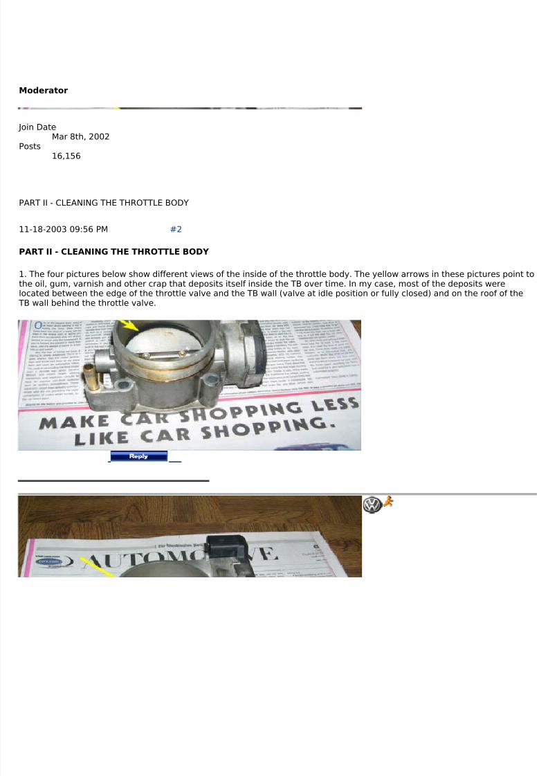
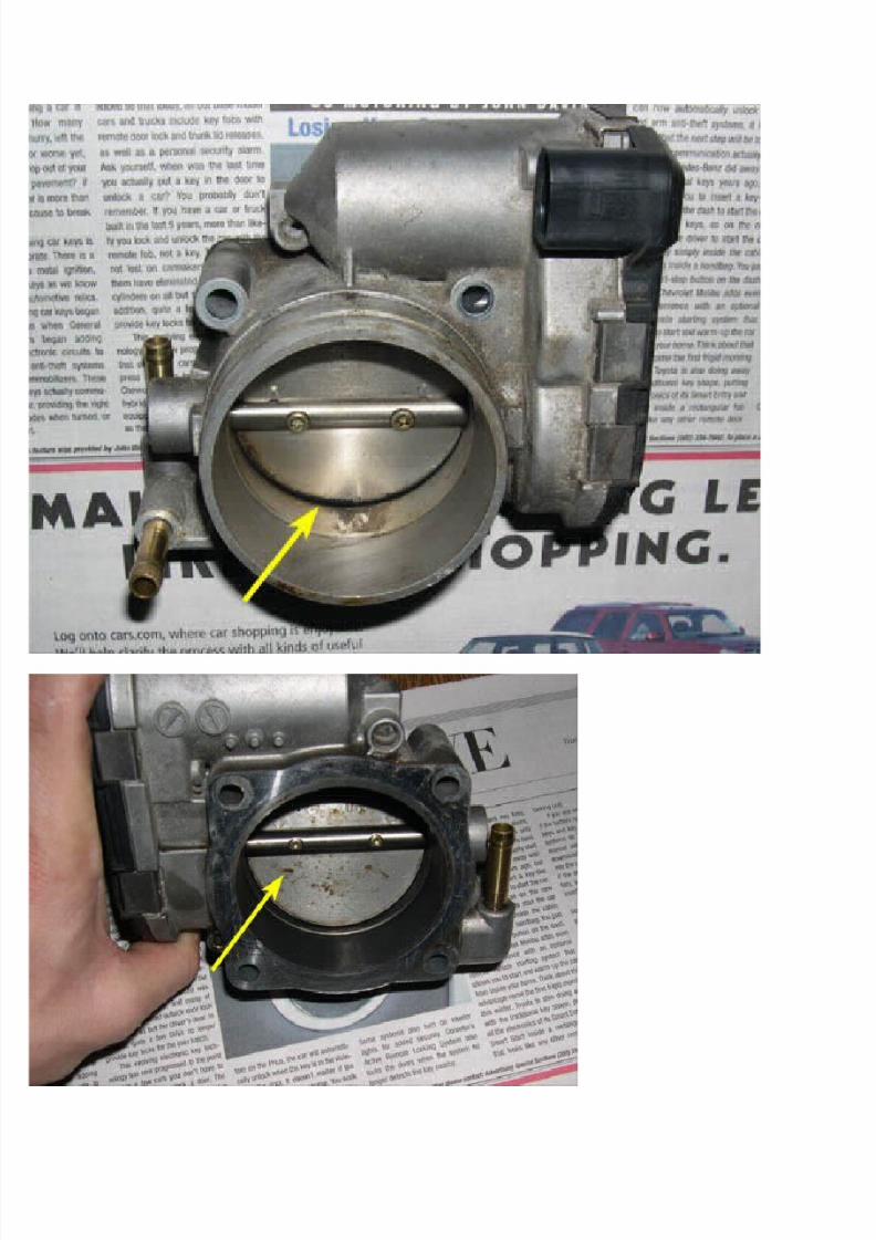
1. The four pictures below show different views of the inside of the throttle body. The yellow arrows in these pictures point tothe oil, gum, varnish and other crap that deposits itself inside the TB over time. In my case, most of the deposits werelocated between the edge of the throttle valve and the TB wall (valve at idle position or fully closed) and on the roof of theTB wall behind the throttle valve.
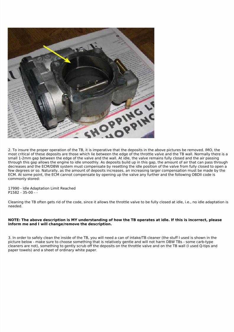
2. To insure the proper operation of the TB, it is imperative that the deposits in the above pictures be removed. IMO, themost critical of these deposits are those which lie between the edge of the throttle valve and the TB wall. Normally there is asmall 1-2mm gap between the edge of the valve and the wall. At idle, the valve remains fully closed and the air passingthrough this gap allows the engine to idle smoothly. As deposits build up in this gap, the amount of air that can pass throughdecreases and the ECM/DBW system must compensate by resetting the idle position of the valve from fully closed to open afew degrees or so. Naturally, as the amount of deposits increases, an increasing larger compensation must be made by the
ECM. At some point, the ECM cannot compensate by opening up the valve any further and the following OBDII code iscommonly stored:
Cleaning the TB often gets rid of the code, since it allows the throttle valve to be fully closed at idle, i.e., no idle adaptation isneeded.
NOTE: The above description is MY understanding of how the TB operates at idle. If this is incorrect, pleaseinform me and I will change/remove the description.
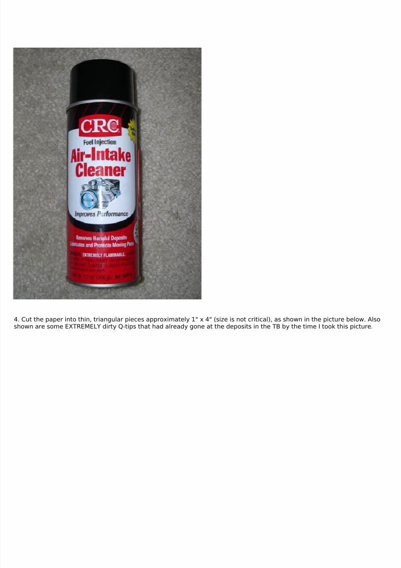
3. In order to safely clean the inside of the TB, you will need a can of intake/TB cleaner (the stuff I used is shown in thepicture below - make sure to choose something that is relatively gentle and will not harm DBW TBs - some carb-typecleaners are not), something to gently scrub off the deposits on the throttle valve and on the TB wall (I used Q-tips andpaper towels) and a sheet of ordinary white paper.
7/29/2019 Removing and Cleaning a Mkiv Throttle Body
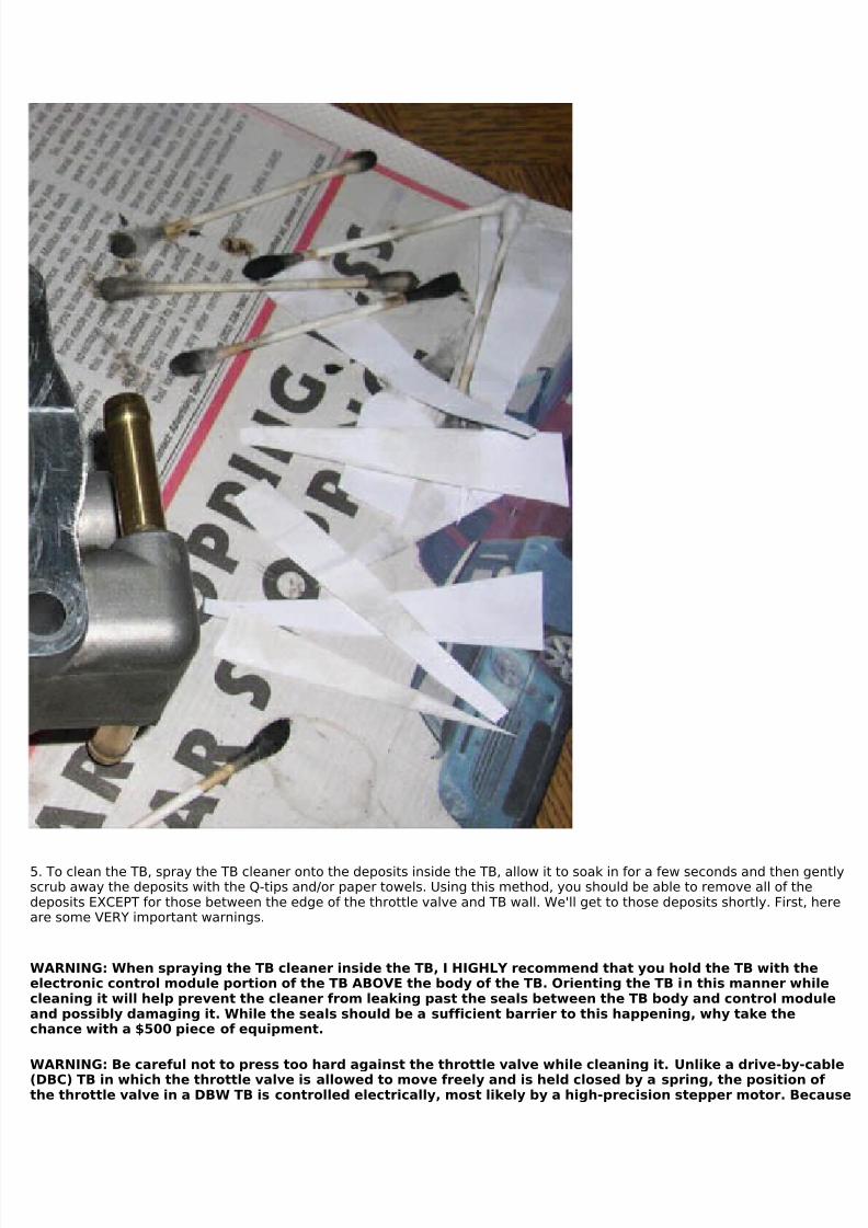
4. Cut the paper into thin, triangular pieces approximately 1" x 4" (size is not critical), as shown in the picture below. Alsoshown are some EXTREMELY dirty Q-tips that had already gone at the deposits in the TB by the time I took this picture.
7/29/2019 Removing and Cleaning a Mkiv Throttle Body
5. To clean the TB, spray the TB cleaner onto the deposits inside the TB, allow it to soak in for a few seconds and then gentlyscrub away the deposits with the Q-tips and/or paper towels. Using this method, you should be able to remove all of thedeposits EXCEPT for those between the edge of the throttle valve and TB wall. We'll get to those deposits shortly. First, hereare some VERY important warnings.
WARNING: When spraying the TB cleaner inside the TB, I HIGHLY recommend that you hold the TB with theelectronic control module portion of the TB ABOVE the body of the TB. Orienting the TB in this manner whilecleaning it will help prevent the cleaner from leaking past the seals between the TB body and control moduleand possibly damaging it. While the seals should be a sufficient barrier to this happening, why take thechance with a $500 piece of equipment.
WARNING: Be careful not to press too hard against the throttle valve while cleaning it. Unlike a drive-by-cable
(DBC) TB in which the throttle valve is allowed to move freely and is held closed by a spring, the position of the throttle valve in a DBW TB is controlled electrically, most likely by a high-precision stepper motor. Because
7/29/2019 Removing and Cleaning a Mkiv Throttle Body
of this, the throttle valve will not move freely and can be easily damaged if forced to move against theresistance of the stepper motor. This does not mean that you cannot apply a small amount of pressure to thethrottle valve with the Q-tip when cleaning it. Just be careful not to use too much pressure. When in doubt,use the least amount of pressure needed to remove the deposits and you should be OK.
6. Since the throttle valve will not move freely due to stepper motor used by the DBW throttle valve controller, you cannotsimply move the throttle valve out of the way to remove the deposits that collect between the edge of the throttle valve andthe TB wall. Instead, I recommend that you use to the small strips of paper to clean this area. Spray a little TB cleaner intothe gap between the edge of the throttle valve and the TB wall and use the corner of one of the strips of paper to carefullyscrape the deposits out of the gap. Once the deposits have been removed from a small area of the gap, slide the paper intothe gap completely and move it back and forth to scrape the deposits out of the gap, similar to using dental floss to removefood from between your teeth. Spray additional cleaner into the gap as needed during this procedure. Using this method, itshould be possible to remove virtually all of the deposits from the gap. Most likely, the gap near the axle for the throttlevalve will be too narrow to get the paper into it, so there may be a very small amount of deposit left remaining in the gapnear the axle. This is not a big deal.
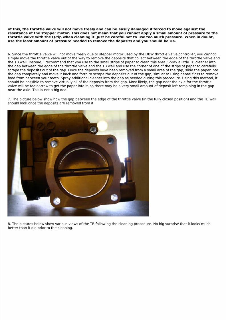
7. The picture below show how the gap between the edge of the throttle valve (in the fully closed position) and the TB wallshould look once the deposits are removed from it.
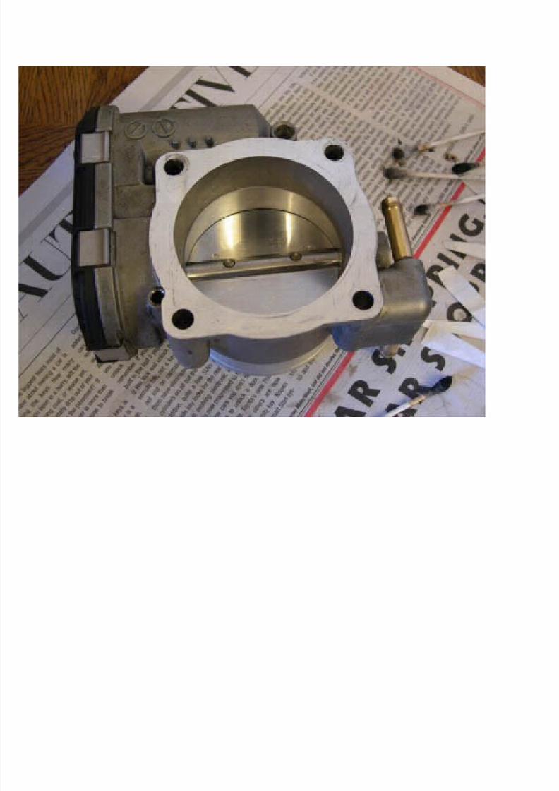
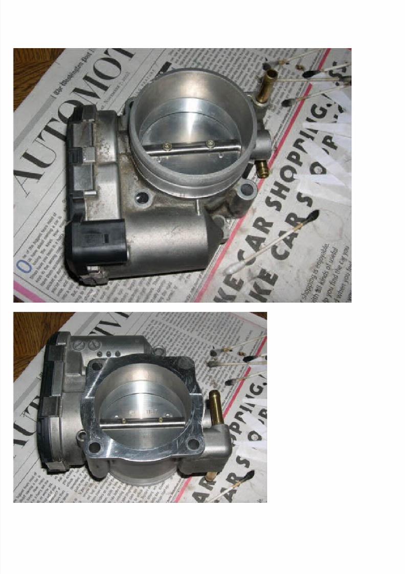
8. The pictures below show various views of the TB following the cleaning procedure. No big surprise that it looks muchbetter than it did prior to the cleaning.
7/29/2019 Removing and Cleaning a Mkiv Throttle Body
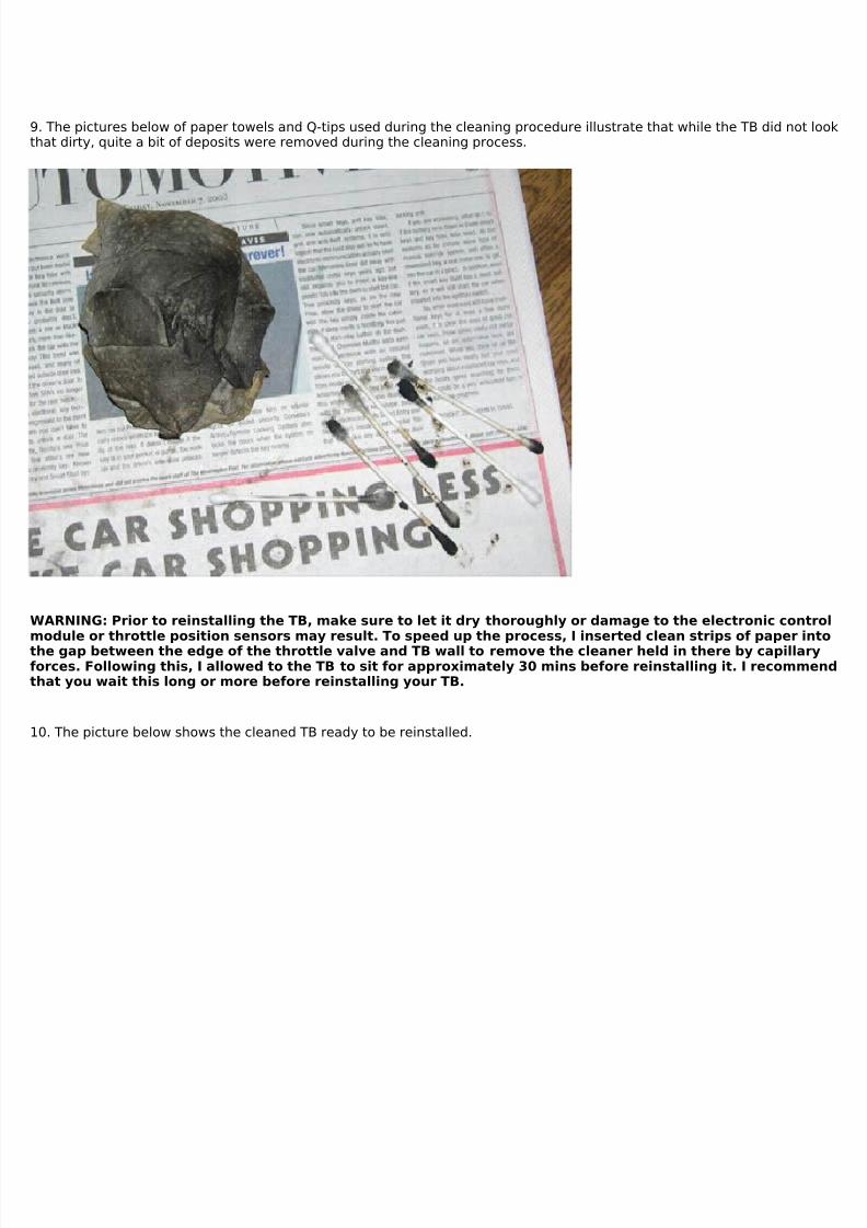
9. The pictures below of paper towels and Q-tips used during the cleaning procedure illustrate that while the TB did not lookthat dirty, quite a bit of deposits were removed during the cleaning process.
WARNING: Prior to reinstalling the TB, make sure to let it dry thoroughly or damage to the electronic controlmodule or throttle position sensors may result. To speed up the process, I inserted clean strips of paper intothe gap between the edge of the throttle valve and TB wall to remove the cleaner held in there by capillaryforces. Following this, I allowed to the TB to sit for approximately 30 mins before reinstalling it. I recommendthat you wait this long or more before reinstalling your TB.
10. The picture below shows the cleaned TB ready to be reinstalled.
7/29/2019 Removing and Cleaning a Mkiv Throttle Body
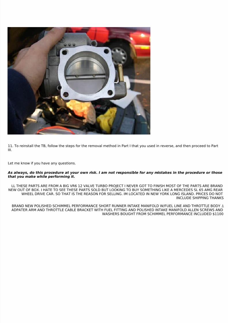
11. To reinstall the TB, follow the steps for the removal method in Part I that you used in reverse, and then proceed to PartIII.
Let me know if you have any questions.
As always, do this procedure at your own risk. I am not responsible for any mistakes in the procedure or thosethat you make while performing it.
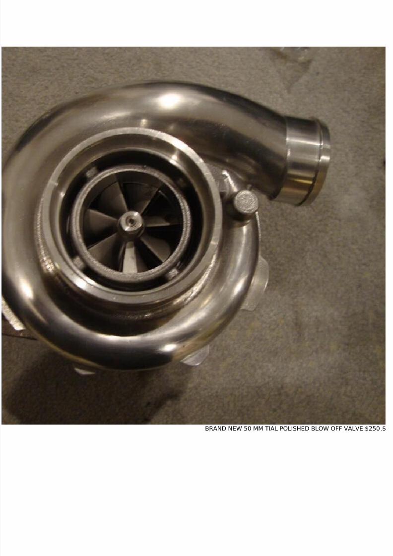
LL THESE PARTS ARE FROM A BIG VR6 12 VALVE TURBO PROJECT I NEVER GOT TO FINISH MOST OF THE PARTS ARE BRANDNEW OUT OF BOX. I HATE TO SEE THESE PARTS SOLD BUT LOOKING TO BUY SOMETHING LIKE A MERCEDES SL 65 AMG REAR
WHEEL DRIVE CAR. SO THAT IS THE REASON FOR SELLING. IM LOCATED IN NEW YORK LONG ISLAND. PRICES DO NOTINCLUDE SHIPPING THANKS
1.BRAND NEW POLISHED SCHIMMEL PERFORMANCE SHORT RUNNER INTAKE MANIFOLD W/FUEL LINE AND THROTTLE BODYADPATER ARM AND THROTTLE CABLE BRACKET WITH FUEL FITTING AND POLISHED INTAKE MANIFOLD ALLEN SCREWS AND
WASHERS BOUGHT FROM SCHIMMEL PERFORMANCE INCLUDED $1100
7/29/2019 Removing and Cleaning a Mkiv Throttle Body
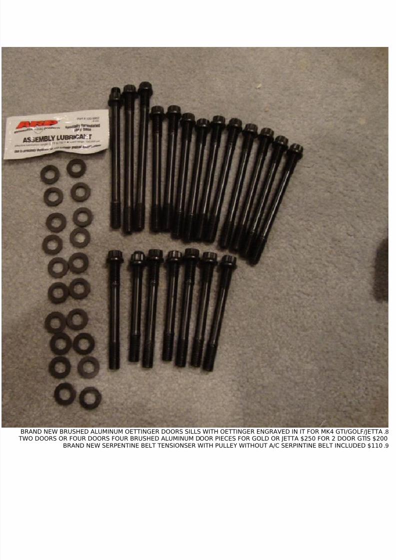
8.BRAND NEW BRUSHED ALUMINUM OETTINGER DOORS SILLS WITH OETTINGER ENGRAVED IN IT FOR MK4 GTI/GOLF/JETTA TWO DOORS OR FOUR DOORS FOUR BRUSHED ALUMINUM DOOR PIECES FOR GOLD OR JETTA $250 FOR 2 DOOR GTIS $200
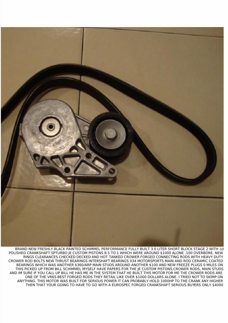
9.BRAND NEW SERPENTINE BELT TENSIONSER WITH PULLEY WITHOUT A/C SERPINTINE BELT INCLUDED $110
10.BRAND NEW FRESHLY BLACK PAINTED SCHIMMEL PERFORMANCE FULLY BUILT 3.0 LITER SHORT BLOCK STAGE 2 WITHPOLISHED CRANKSHAFT SPTURBO JE CUSTOM PISTONS 8.5 TO 1 WHICH WERE AROUND $1000 ALONE .100 OVERBORE. NEW
RINGS CLEARANCES CHECKED DECKED AND HOT TANKED CROWER FORGED CONNECTING RODS WITH HEAVY DUTYCROWER ROD BOLTS NEW THRUST BEARINGS INTERSHAFT BEARINGS 034 MOTORSPORTS MAIN AND ROD CERAMIC COATED
BEARINGS WHICH WAS ANOTHER $360/ARP MAIN STUDS AROUND ANOTHER $100 AND NEW FREEZE PLUGS 0 MILES ON THIS PICKED UP FROM BILL SCHIMMEL MYSELF HAVE PAPERS FOR THE JE CUSTOM PISTONS,CROWER RODS, MAIN STUDS
AND IM SURE IF YOU CALL UP BILL HE HAS ME IN THE SYSTEM THAT HE BUILT THIS MOTOR FOR ME THE CROWER RODS AREONE OF THE VR6S BEST FORGED RODS THEY RETAIL LIKE OVER $1000 DOLLARS ALONE. I TRIED NOT TO SKIMP ON
ANYTHING. THIS MOTOR WAS BUILT FOR SERIOUS POWER IT CAN PROBABLY HOLD 1000HP TO THE CRANK ANY HIGHER THEN THAT YOUR GOING TO HAVE TO GO WITH A EUROSPEC FORGED CRANKSHAFT SERIOUS BUYERS ONLY $4000
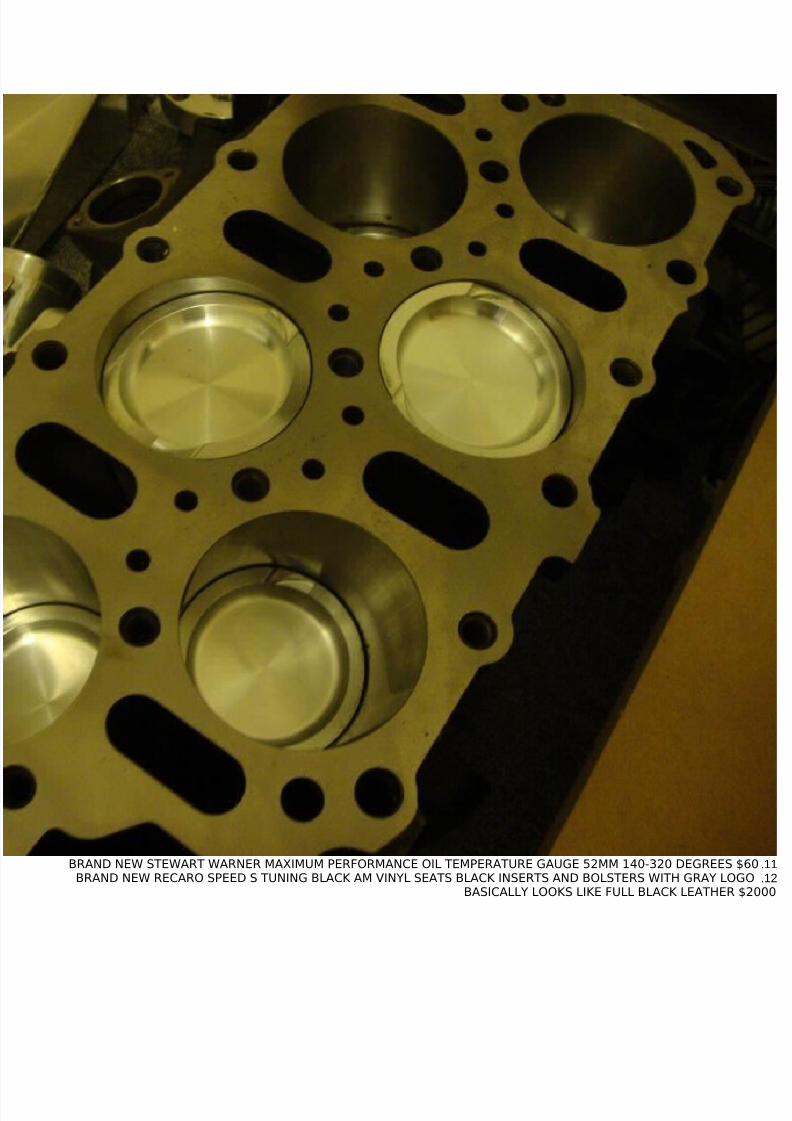
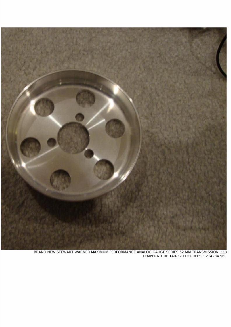
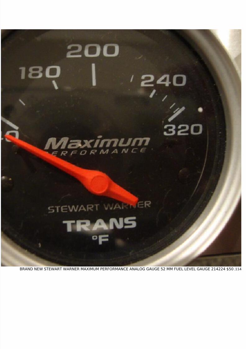
11.BRAND NEW STEWART WARNER MAXIMUM PERFORMANCE OIL TEMPERATURE GAUGE 52MM 140-320 DEGREES $6012.BRAND NEW RECARO SPEED S TUNING BLACK AM VINYL SEATS BLACK INSERTS AND BOLSTERS WITH GRAY LOGO
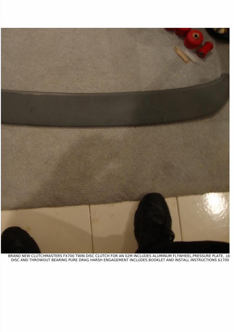
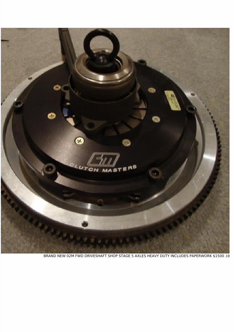
18.BRAND NEW CLUTCHMASTERS FX700 TWIN DISC CLUTCH FOR AN 02M INCLUDES ALUMINUM FLYWHEEL,PRESSURE PLATE,DISC AND THROWOUT BEARING PURE DRAG HARSH ENGAGEMENT INCLUDES BOOKLET AND INSTALL INSTRUCTIONS $1700
21.BRAND NEW SCHIMMEL PERFORMANCE POLISHED WATER TO AIR INTERCOOLER SYSTEM /INCLUDING WATER TO AIRINTERCOOLER/INCLUDING 3 GALLON WATER TANK/ MEZEINER WATER PUMP/ LONG RUBBER BLACK HOSE AND BLACK LONG
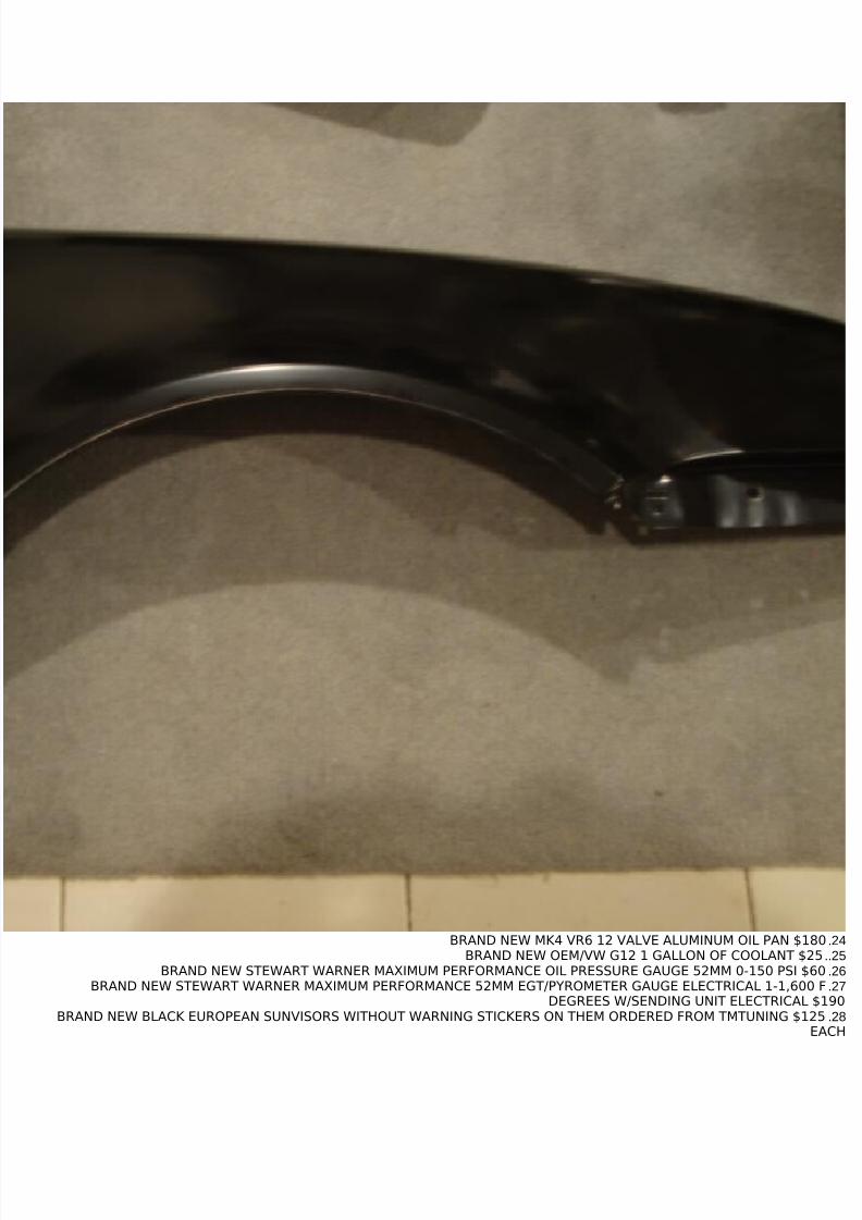
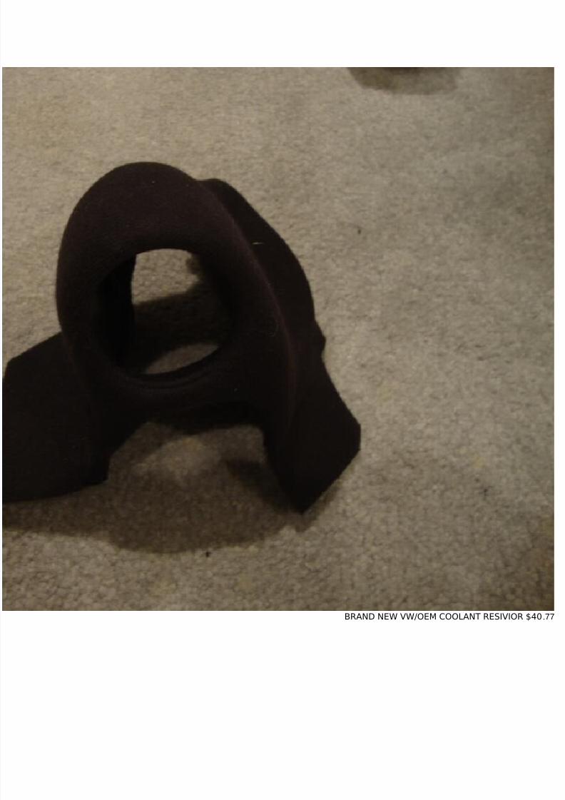
24.BRAND NEW MK4 VR6 12 VALVE ALUMINUM OIL PAN $18025..BRAND NEW OEM/VW G12 1 GALLON OF COOLANT $2526.BRAND NEW STEWART WARNER MAXIMUM PERFORMANCE OIL PRESSURE GAUGE 52MM 0-150 PSI $6027.BRAND NEW STEWART WARNER MAXIMUM PERFORMANCE 52MM EGT/PYROMETER GAUGE ELECTRICAL 1-1,600 F
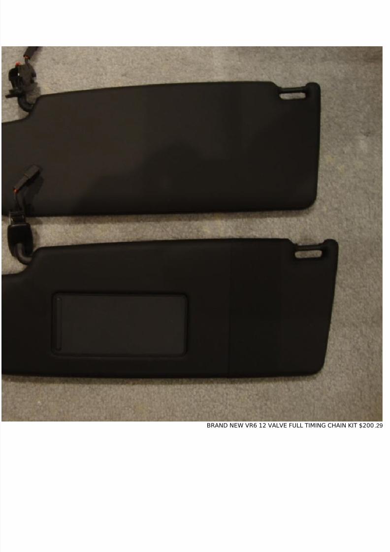
DEGREES W/SENDING UNIT ELECTRICAL $19028.BRAND NEW BLACK EUROPEAN SUNVISORS WITHOUT WARNING STICKERS ON THEM ORDERED FROM TMTUNING $125
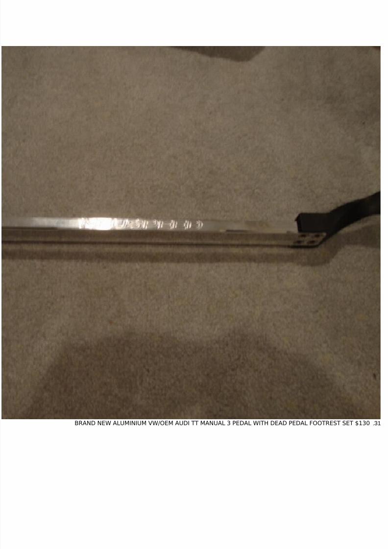
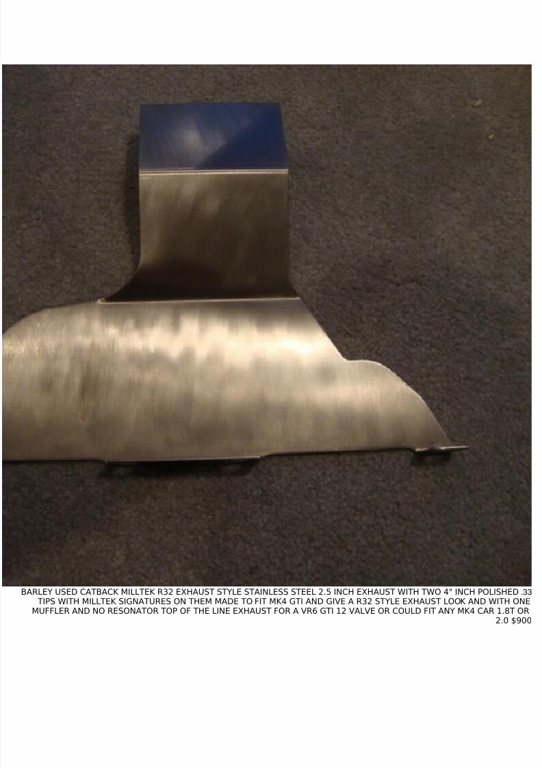
33.BARLEY USED CATBACK MILLTEK R32 EXHAUST STYLE STAINLESS STEEL 2.5 INCH EXHAUST WITH TWO 4" INCH POLISHED TIPS WITH MILLTEK SIGNATURES ON THEM MADE TO FIT MK4 GTI AND GIVE A R32 STYLE EXHAUST LOOK AND WITH ONE
MUFFLER AND NO RESONATOR TOP OF THE LINE EXHAUST FOR A VR6 GTI 12 VALVE OR COULD FIT ANY MK4 CAR 1.8T OR2.0 $900
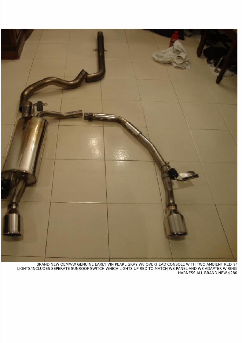
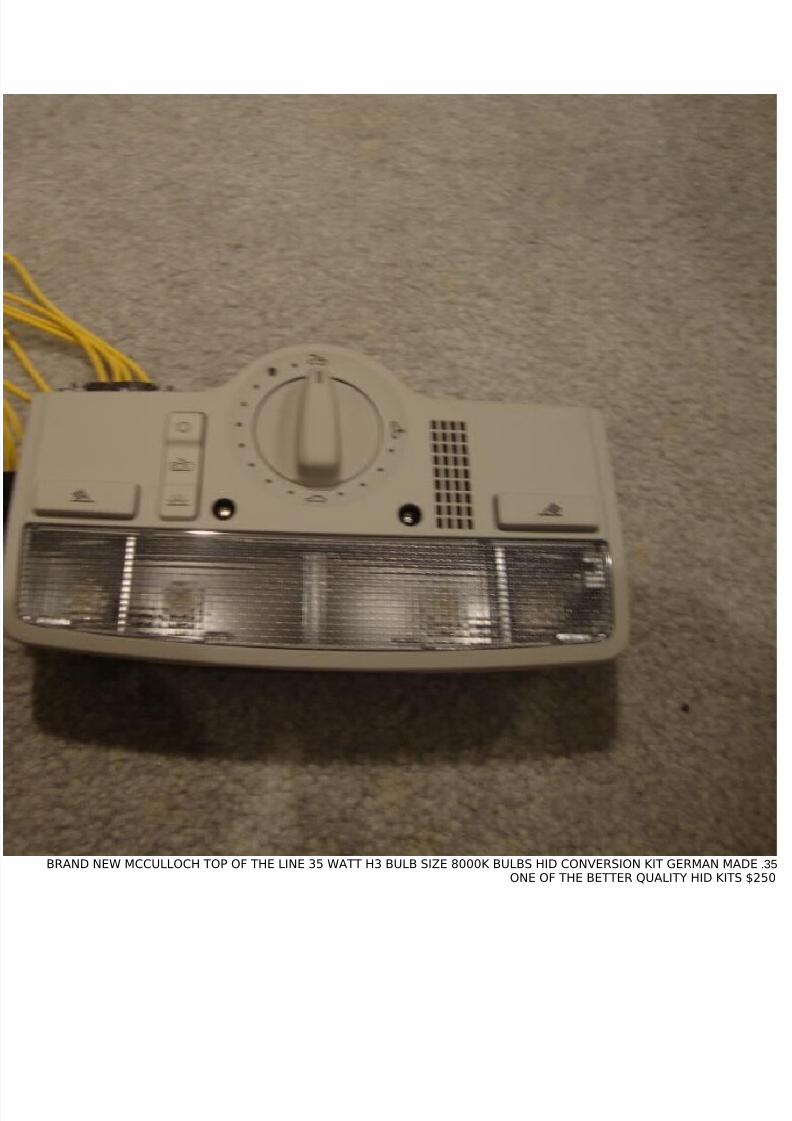
34.BRAND NEW OEM/VW GENUINE EARLY VIN PEARL GRAY W8 OVERHEAD CONSOLE WITH TWO AMBIENT REDLIGHTS/INCLUDES SEPERATE SUNROOF SWITCH WHICH LIGHTS UP RED TO MATCH W8 PANEL AND W8 ADAPTER WIRING
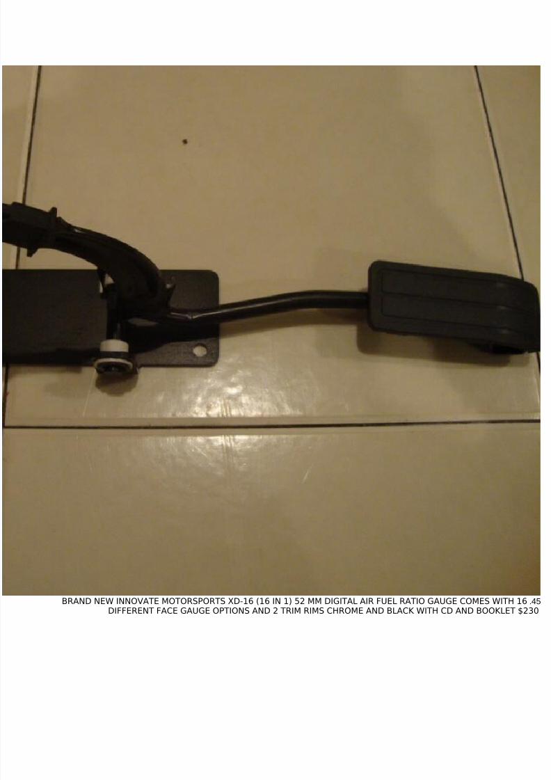
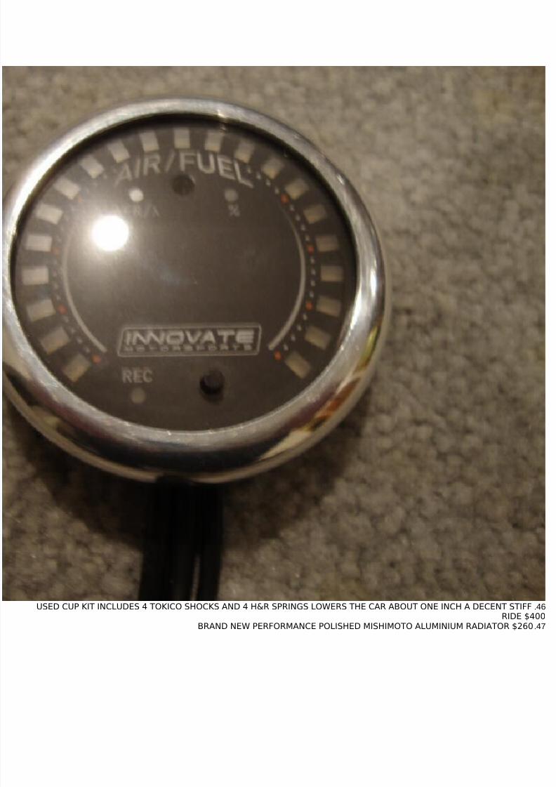
45.BRAND NEW INNOVATE MOTORSPORTS XD-16 (16 IN 1) 52 MM DIGITAL AIR FUEL RATIO GAUGE COMES WITH 16DIFFERENT FACE GAUGE OPTIONS AND 2 TRIM RIMS CHROME AND BLACK WITH CD AND BOOKLET $230
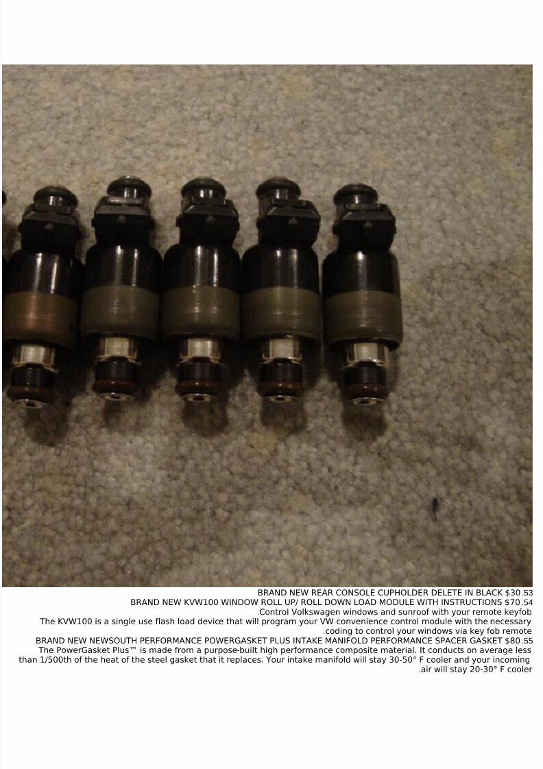
53.BRAND NEW REAR CONSOLE CUPHOLDER DELETE IN BLACK $3054.BRAND NEW KVW100 WINDOW ROLL UP/ ROLL DOWN LOAD MODULE WITH INSTRUCTIONS $70
Control Volkswagen windows and sunroof with your remote keyfob.
The KVW100 is a single use flash load device that will program your VW convenience control module with the necessarycoding to control your windows via key fob remote.
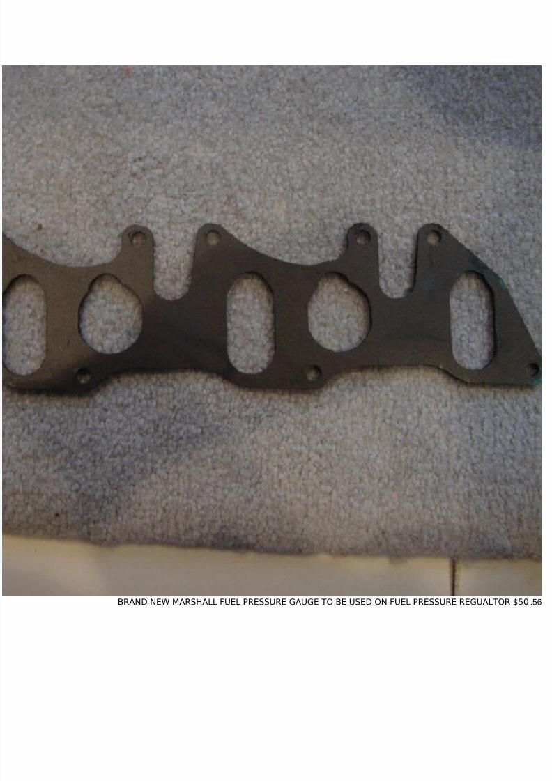
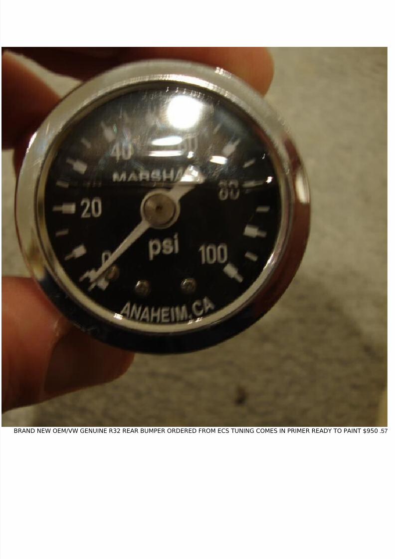
55.BRAND NEW NEWSOUTH PERFORMANCE POWERGASKET PLUS INTAKE MANIFOLD PERFORMANCE SPACER GASKET $80 The PowerGasket Plus™ is made from a purpose-built high performance composite material. It conducts on average less
than 1/500th of the heat of the steel gasket that it replaces. Your intake manifold will stay 30-50° F cooler and your incoming
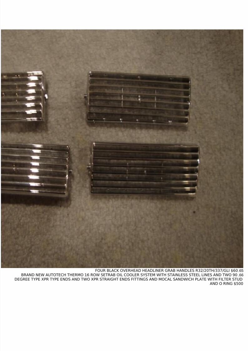
65.FOUR BLACK OVERHEAD HEADLINER GRAB HANDLES R32/20TH/337/GLI $6066.BRAND NEW AUTOTECH THERMO 16 ROW SETRAB OIL COOLER SYSTEM WITH STAINLESS STEEL LINES AND TWO 90
DEGREE TYPE XPR TYPE ENDS AND TWO XPR STRAIGHT ENDS FITTINGS AND MOCAL SANDWICH PLATE WITH FILTER STUDAND O RING $500
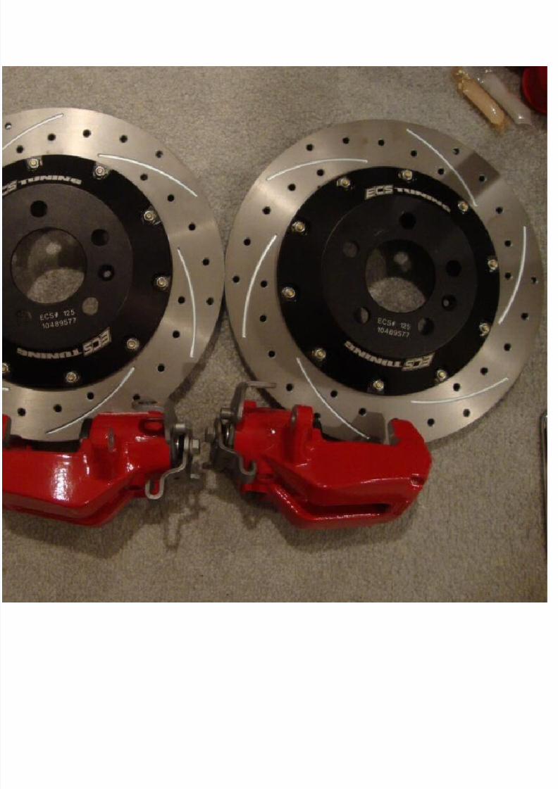
72. TWO BLACK R32/337/20TH/GLI SIDE DOME LIGHTS ON HEADLINER $25 EACH73.BRAND NEW COOLANT TEMP SWITCH $2574.BRAND NEW ECS TUNING REAR BIG BRAKE STAGE ONE VERSION TWO BIG BRAKE KIT WITH 12.1 INCH CROSS DRILLED
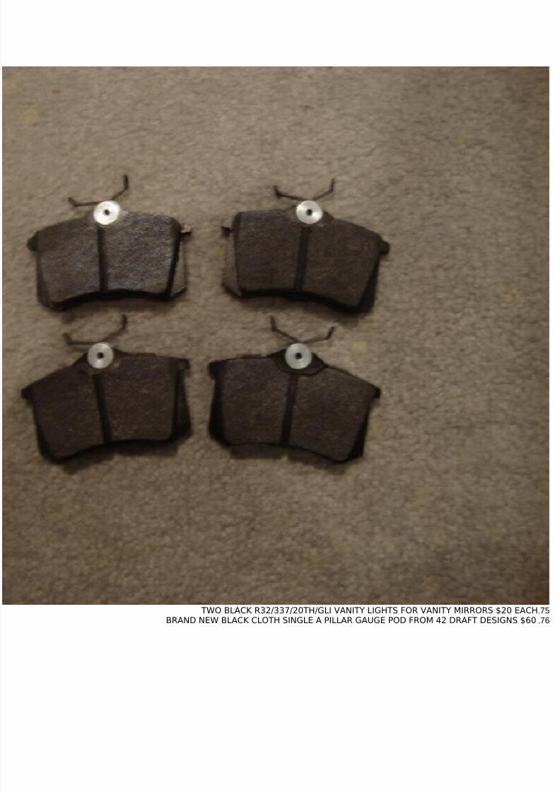
AND SLOTTED ROTORS AND RED CALIPERS WITH HAWK HPS PERFORMANCE PADS $1200
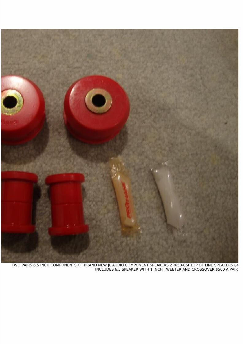
84. TWO PAIRS 6.5 INCH COMPONENTS OF BRAND NEW JL AUDIO COMPONENT SPEAKERS ZR650-CSI TOP OF LINE SPEAKERSINCLUDES 6.5 SPEAKER WITH 1 INCH TWEETER AND CROSSOVER $500 A PAIR
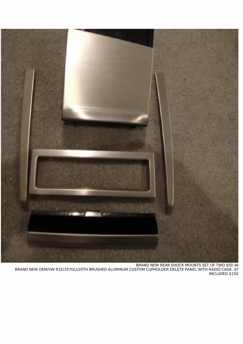
92.BRAND NEW OEM/VW R32/337/GLI/20TH BRUSHED ALUMINUM CLIMATRONIC TRIM PIECE $8093.BRAND NEW OEM/VW R32/337/GLI/20TH BRUSHED ALUMINUM LEFT SIDE DASH INSERT $8094.BRAND NEW OEM/VW R32/337/GLI/20TH BRUSHED ALUMINUM RIGHT SIDE DASH INSERT $8094.BRAND NEW OEM/VW R32/337/GLI/20TH BRUSHED ALUMINUM LOWER DASH INSERT $6095.BRAND NEW OEM/VW R32/337/GLI/20TH BRUSHED ALUMINUM ASHTRAY COVER $60
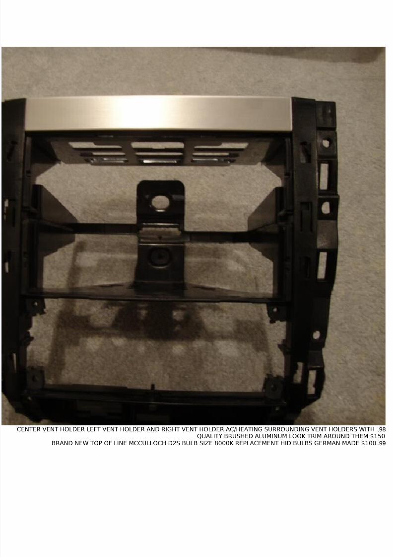
98.CENTER VENT HOLDER LEFT VENT HOLDER AND RIGHT VENT HOLDER AC/HEATING SURROUNDING VENT HOLDERS WITHQUALITY BRUSHED ALUMINUM LOOK TRIM AROUND THEM $150
99.BRAND NEW TOP OF LINE MCCULLOCH D2S BULB SIZE 8000K REPLACEMENT HID BULBS GERMAN MADE $100
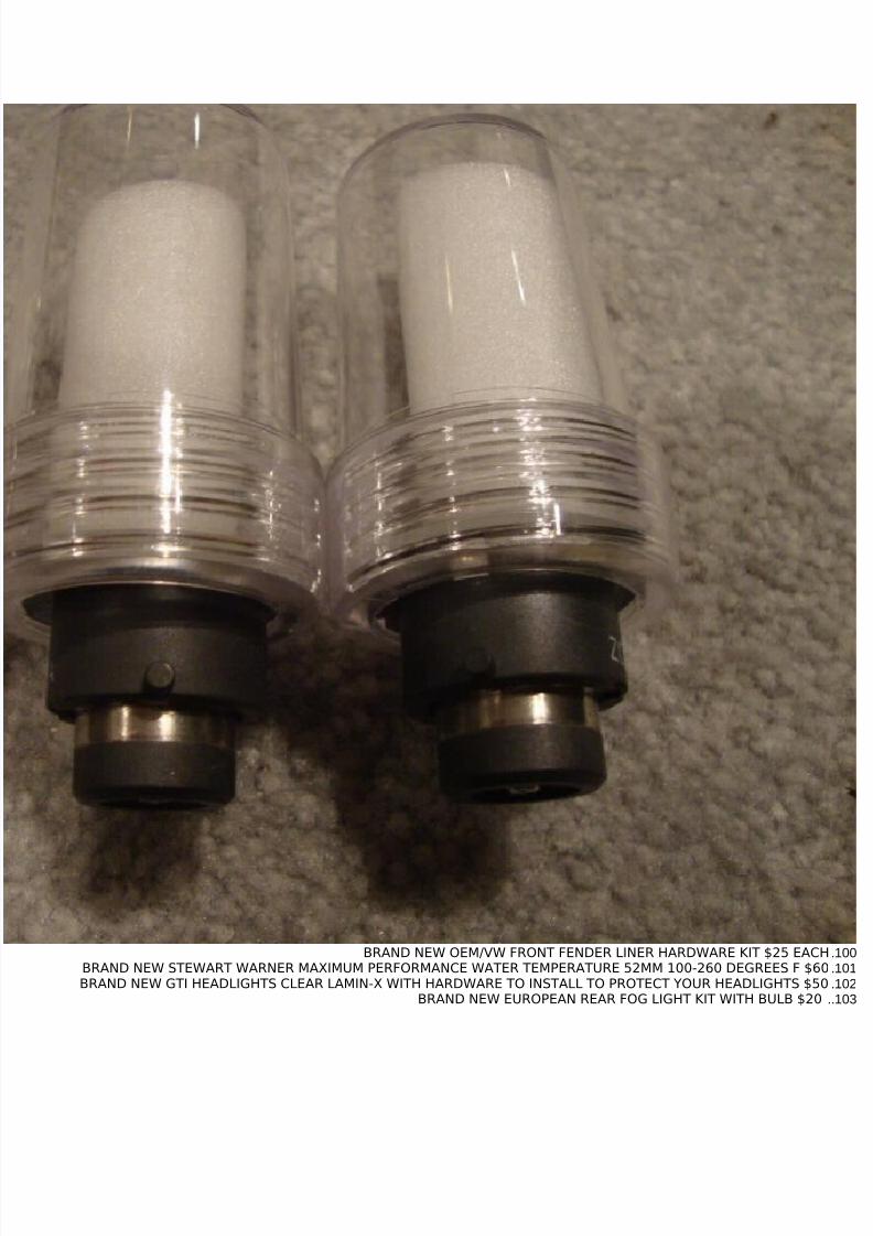
100.BRAND NEW OEM/VW FRONT FENDER LINER HARDWARE KIT $25 EACH101.BRAND NEW STEWART WARNER MAXIMUM PERFORMANCE WATER TEMPERATURE 52MM 100-260 DEGREES F $60102.BRAND NEW GTI HEADLIGHTS CLEAR LAMIN-X WITH HARDWARE TO INSTALL TO PROTECT YOUR HEADLIGHTS $50103..BRAND NEW EUROPEAN REAR FOG LIGHT KIT WITH BULB $20
107.BARLEY USED LOWER ALUMINUM VF ENGINEERING ENGINE PENDULUM MOUNT W/HARDWARE $180108.BRAND NEW 12 VALVE VALVE COVER GASKET TO FIT METAL VALVE COVERS ONLY $20109.BRAND NEW BOTH 12 VALVE STEEL EXHAUST MANIFOLD GASKETS $30110.BARELY USED POLISHED ALUMINUM UNORTHODOX RACING PERFORMANCE PULLEY KIT INCLUDES CRANK PULLEY POWER
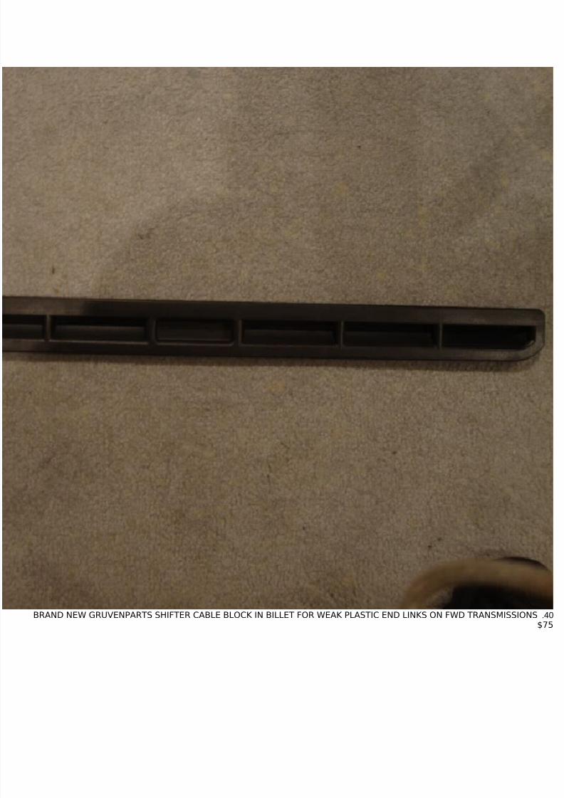
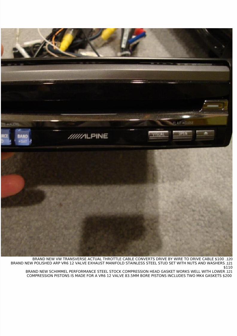
120.BRAND NEW VW TRANSVERSE ACTUAL THROTTLE CABLE CONVERTS DRIVE BY WIRE TO DRIVE CABLE $100121.BRAND NEW POLISHED ARP VR6 12 VALVE EXHAUST MANIFOLD STAINLESS STEEL STUD SET WITH NUTS AND WASHERS
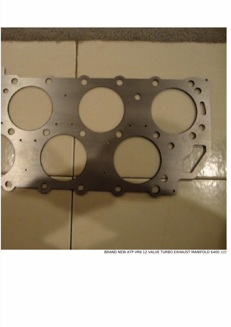
$110121.BRAND NEW SCHIMMEL PERFORMANCE STEEL STOCK COMPRESSION HEAD GASKET WORKS WELL WITH LOWER
COMPRESSION PISTONS IS MADE FOR A VR6 12 VALVE 83.5MM BORE PISTONS INCLUDES TWO MK4 GASKETS $200
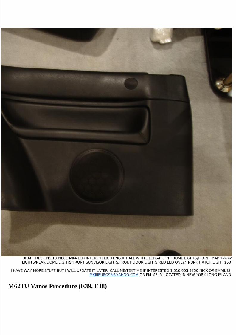
124.42DRAFT DESIGNS 10 PIECE MK4 LED INTERIOR LIGHTING KIT ALL WHITE LEDS/FRONT DOME LIGHTS/FRONT MAPLIGHTS/REAR DOME LIGHTS/FRONT SUNVISOR LIGHTS/FRONT DOOR LIGHTS RED LED ONLY/TRUNK HATCH LIGHT $50
I HAVE WAY MORE STUFF BUT I WILL UPDATE IT LATER. CALL ME/TEXT ME IF INTERESTED 1 516 603 3850 NICK OR EMAIL [email protected] OR PM ME IM LOCATED IN NEW YORK LONG ISLAND
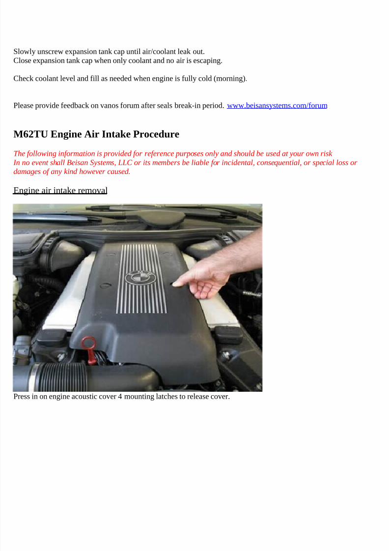
The following information is provided for reference purposes only and should be used at your own risk
In no event shall Beisan Systems, LLC or its members be liable for incidental, consequential, or special loss ordamages of any kind however caused.
Introduction
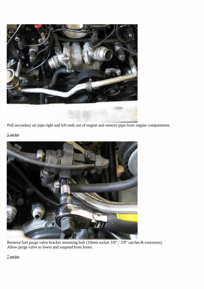
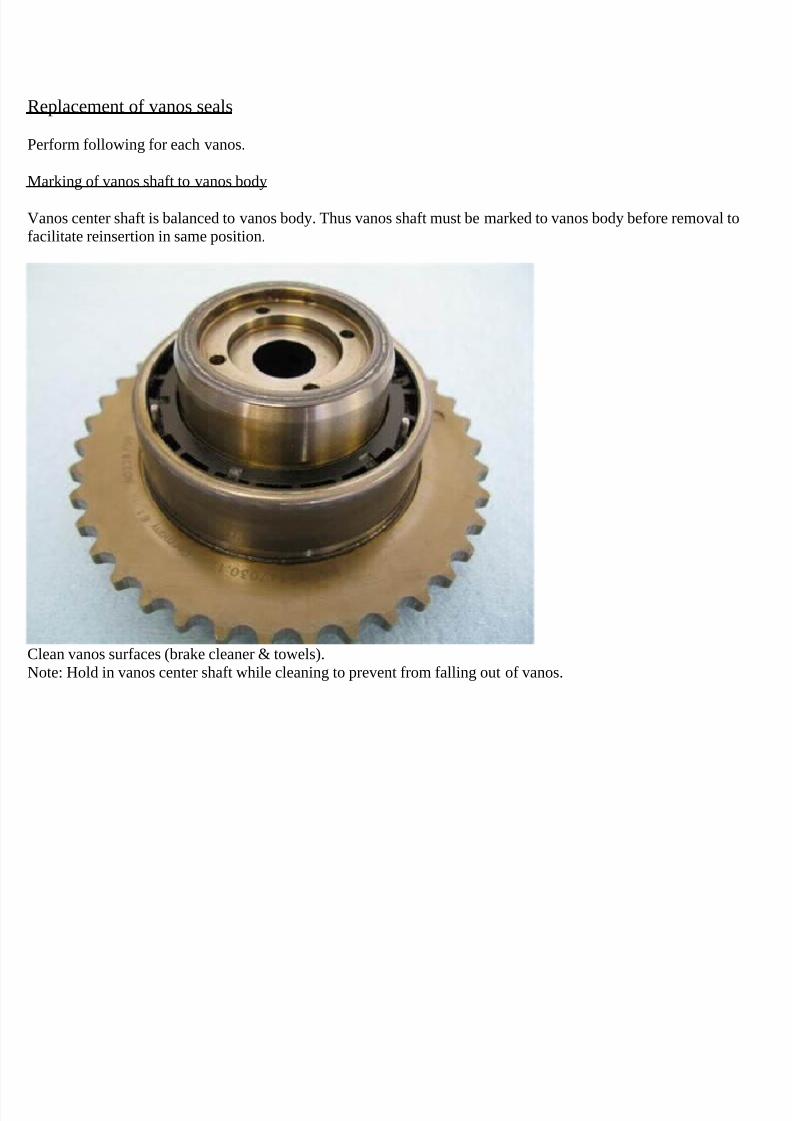
“Vanos” is BMW’s name for its variable valve timing units. Vanos units take on various shapes and design accordingto car year and model (engine model). The vanos discussed here is BMW part # 11-36-1-438-694. It’s a single vanos,meaning only the intake valve timing is varied. This vanos unit is part of BMW 8-cylinder engine M62TU. Thisengine was incorporated in multiple car models during years 1999-2005. It’s found in the 5-series E39 99-03, 7-seriesE38 99-01, X5 E53 99-03, Land Rover 03-05, Range Rover 03-05.
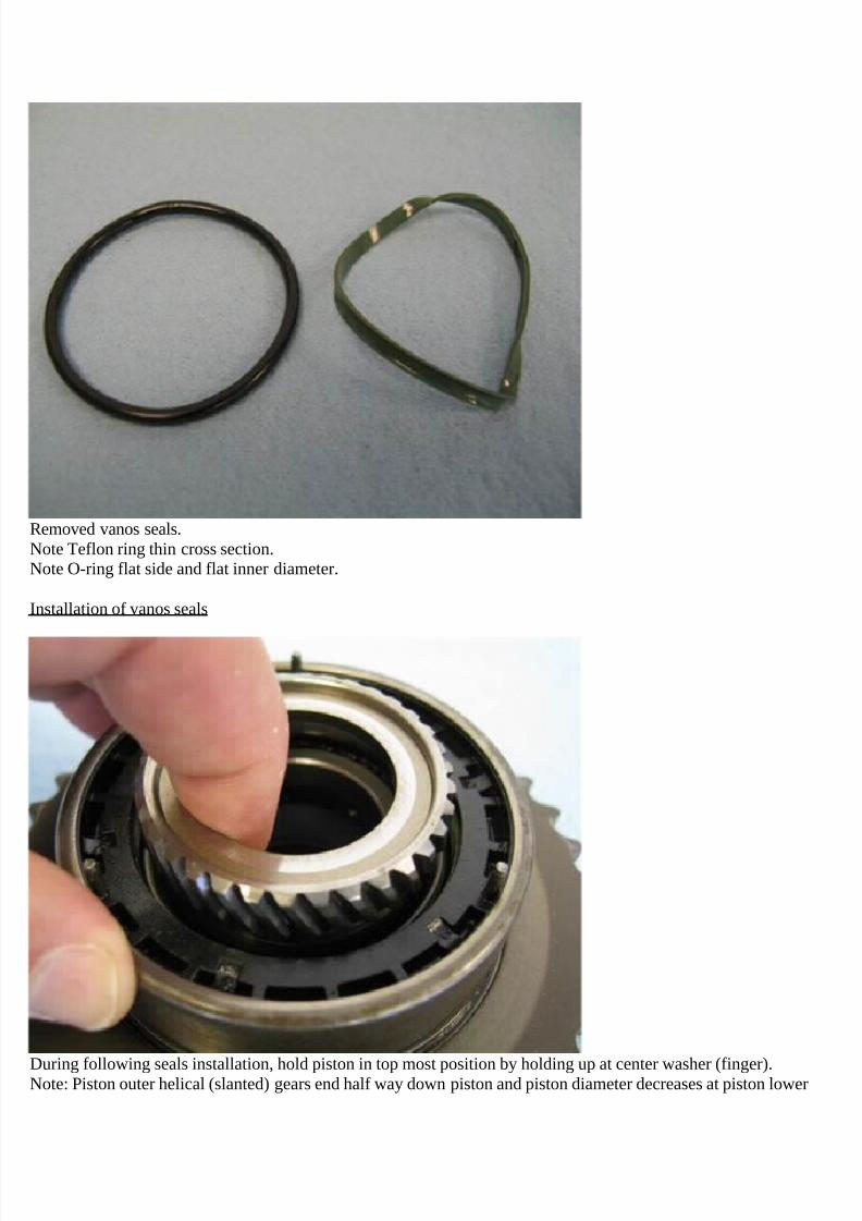
This vanos has been experiencing a failure. It has been diagnosed that the failure is due to deterioration of the vanosseals. The vanos seals encompass an O-ring at the outer perimeter of the vanos plastic housing and a dynamic rod sealat the inner perimeter of the same plastic housing.
The vanos plastic housing outer perimeter O-ring is made of Viton, the correct material, but is experiencingcompression set (flattening) over time and use and is failing in its function.
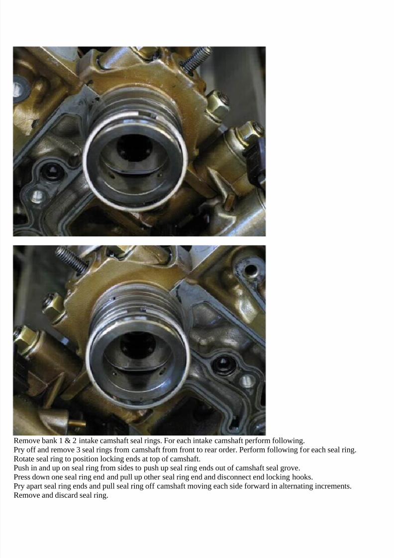
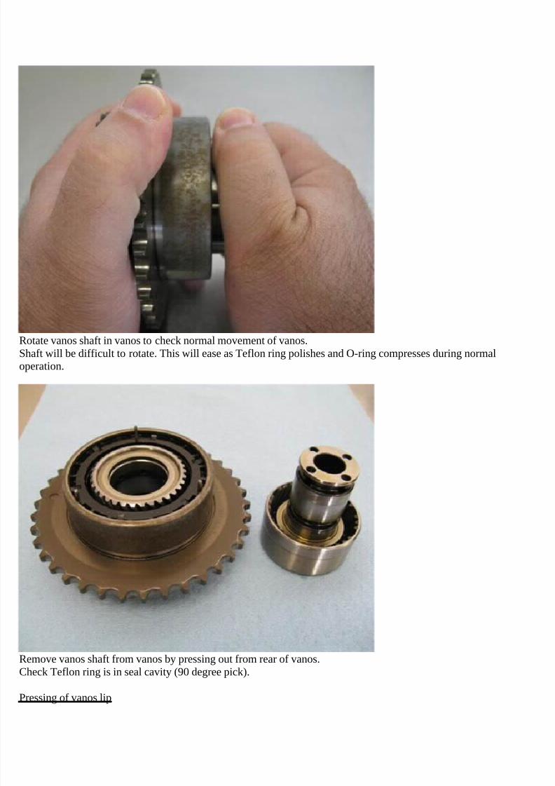
The vanos plastic housing inner perimeter rod seal is made of a Teflon ring and backing O-ring. The Teflon ring ismade from pigment modified (turquoise) Teflon. This slight variation on virgin Teflon is slightly more resistant towear and deformation than virgin Teflon. But it is still is very susceptible to wear and deformation. The Teflon ringhas been found to lose significant material due to wear. This loss of material is causing the Teflon ring to lose itsfunctional characteristics and thus cause the vanos to fail.
The rod seal O-ring is made from Viton, the correct material for the application, but is experiencing notable
compression set (flattening). This compression set further reduces the seal material fill in the seal cavity and thusfurther compounds the Teflon ring material wear failure. Thus replacing the O-ring is appropriate when replacing theTeflon ring.
BMW has been engaged regarding other vanos failures in the past but has elected to not address the issues, “Nofurther development will be done”. New vanos units are being sold with the same pigment modified Teflon ring.BMW does not provide the vanos rod seal as a separate part.
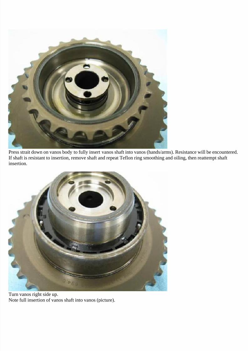
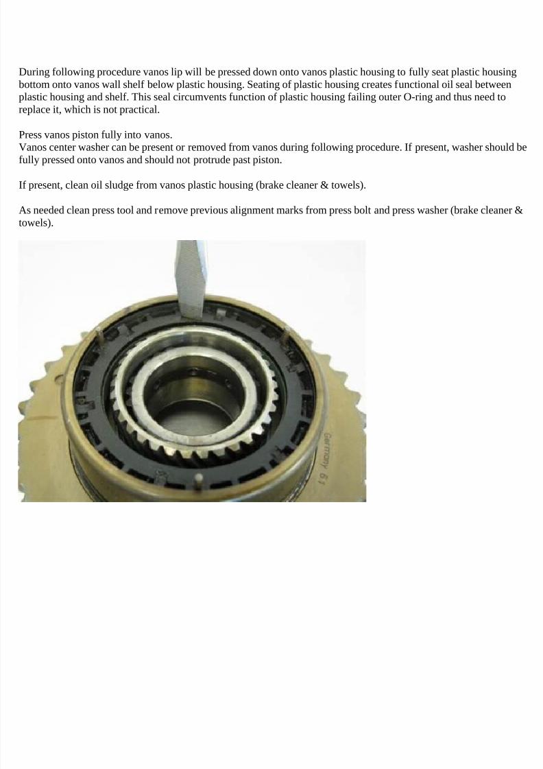
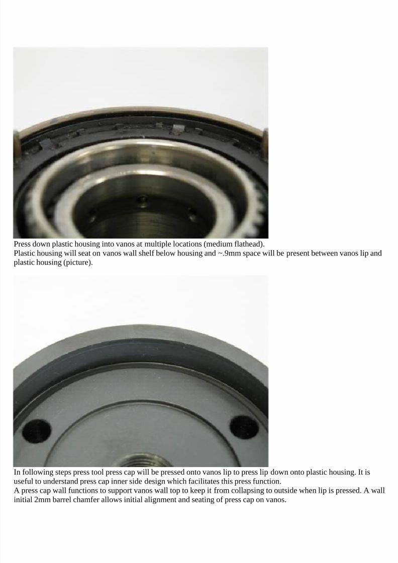
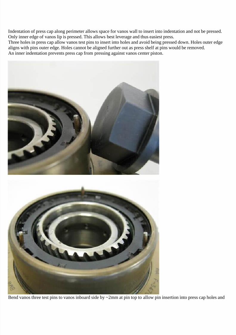
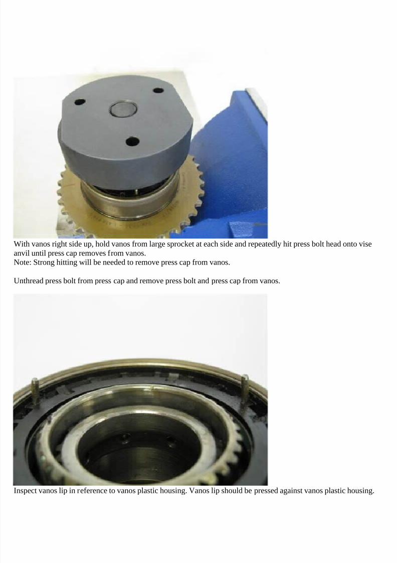
Due to the sealed nature of this vanos the plastic housing outer perimeter O-ring can’t be accessed and replaced.Fortunately a method was found to slightly modify the vanos to circumvent the function for this O-ring and thus theneed to replace it. The vanos top lip is pressed down onto the plastic housing to press the plastic housing down and
seat it on a vanos wall shelf. This seating creates a functional oil seal that provides the oil chamber seal the O-ringwas intended to achieve.
The rod seal Teflon ring can be replaced with a Teflon ring made from a very low friction Teflon compound but onethat has significantly better resistance to wear and deformation. A low friction coefficient is necessary for thisapplication due to the low engine oil pressure and the large rotary vanos movement. To achieve such low friction andlow wear properties simultaneously requires special Teflon materials that are not readily available from sealscompanies. A special high grade Teflon carbon filler is available for such an application. This filler is used on the i6vanos OEM Teflon rings and has been used by Beisan for the replacement Teflon rings for the i6 vanos units forsome time. This special material is appropriate for this vanos application. The Teflon ring is not a standard part andneeds to be semi-custom manufactured.
7/29/2019 Removing and Cleaning a Mkiv Throttle Body
Viton material O-rings have variations in characteristics. The Beisan sourced Viton O-rings have been shown overtime to have excellent compression set characteristics. Thus the rod seal O-ring is replaced with this Viton materialO-ring.
This vanos has one rod seal comprised of a Teflon ring and O-ring. There are two vanos units per engine, one for
each engine head.
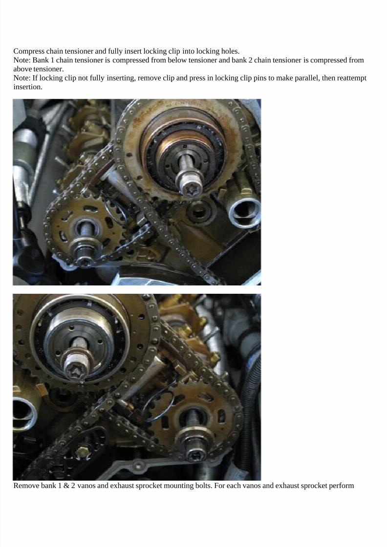
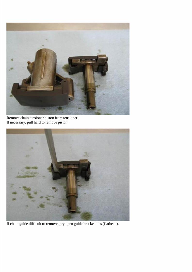
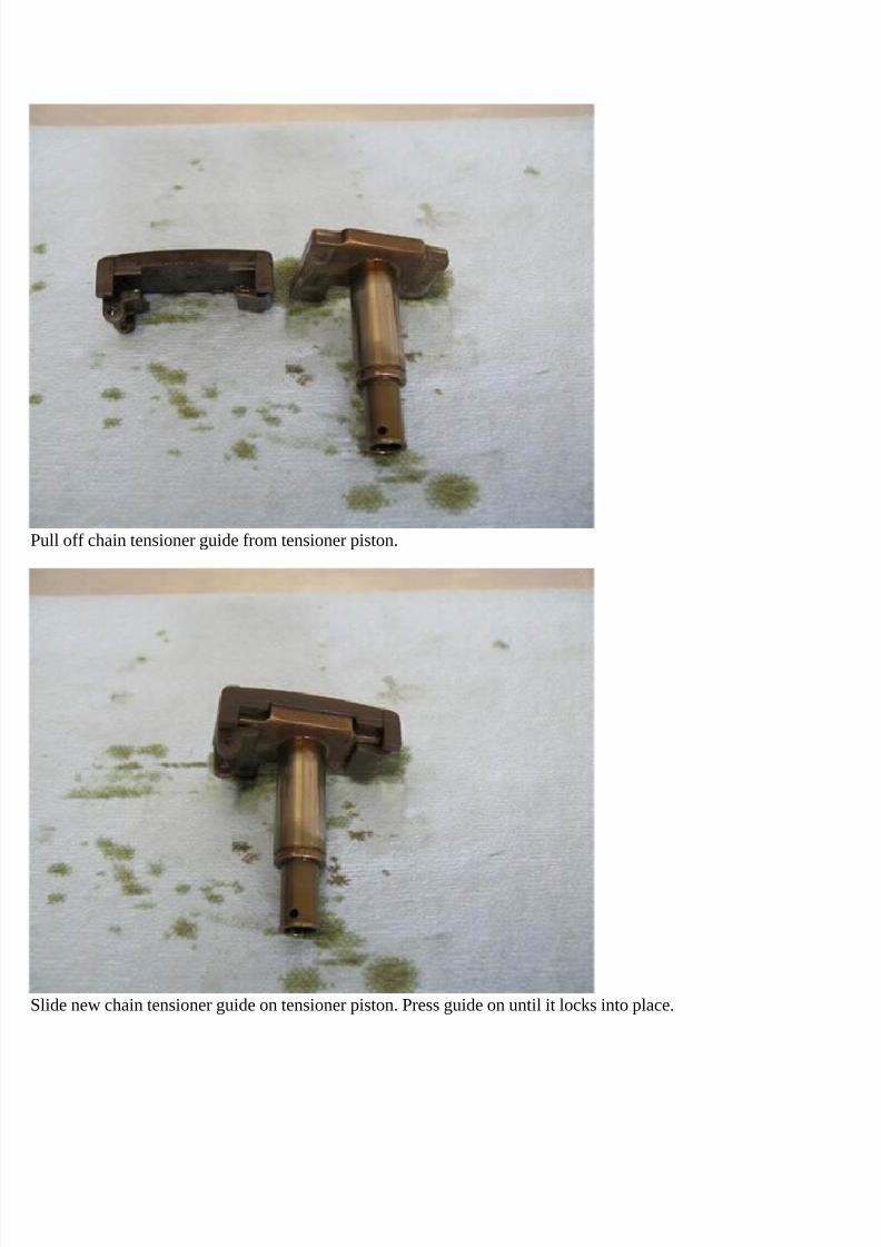
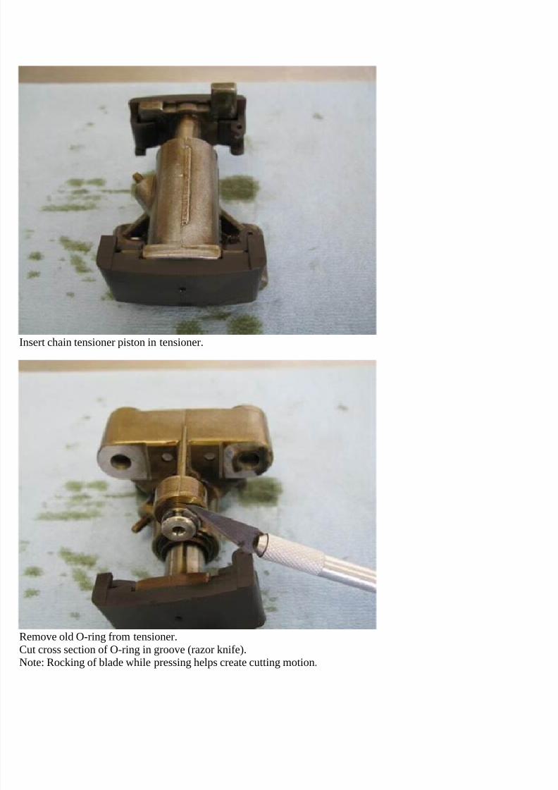
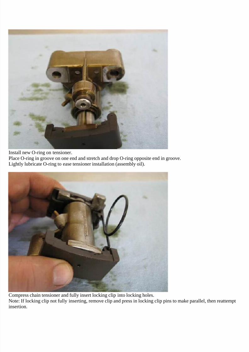
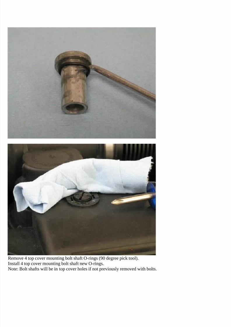
A vanos seals/O-rings repair kit can be acquired through Beisan Systems (bee-saan),www.beisansystems.com/products. It includes a vanos replacement set of high grade carbon Teflon rings and VitonO-rings. The kit also includes two O-rings for the secondary air pipe, two O-rings for the two camshaft chaintensioners, and 4 O-rings for the two engine covers two mounting bolt shafts. These extra O-rings are needed duringthe vanos seals repair and are provided as a value-add to the kit.A vanos press tool is also available from Beisan Systems to press the vanos lip to overcome the need to replace theinaccessible plastic housing outer perimeter O-ring.
Symptoms
Cold start vanos rattle.Warm idle vanos clatter, similar to diesel engine.Loss of low end torque/power and uneven power delivery.
Diagnosis
The failure symptoms can be relied on for the diagnosis. The cold start rattle is the initial indication, and is thenflowed by the warm idle clatter.
Vanos Components
This vanos system (variable valve timing) is made of multiple components. Further, the main vanos unit is frictionwelded as one part with an insert shaft and thus cannot be easily assessed. This section attempts to describe thesystem components and provide a breakdown of the vanos unit parts.
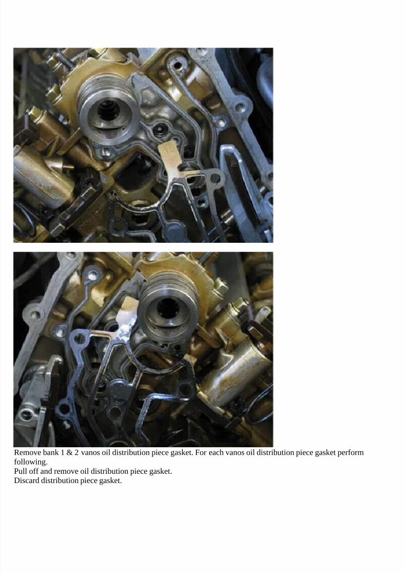
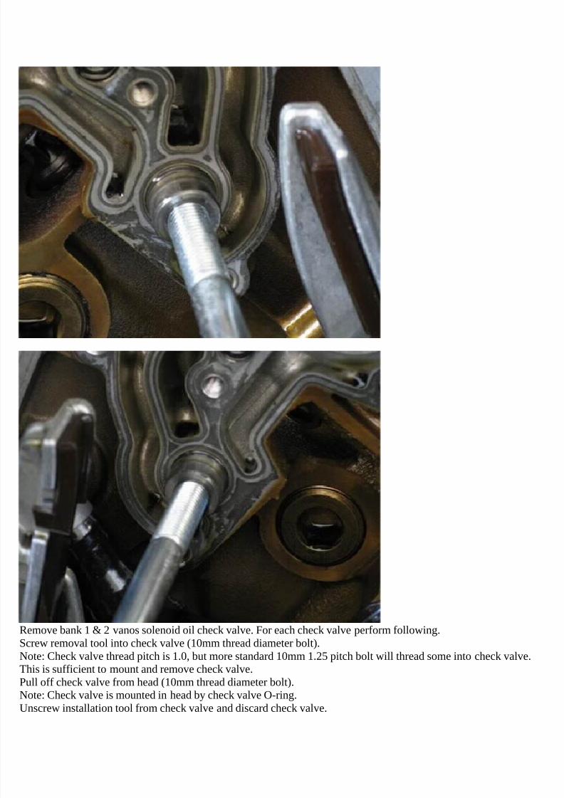
Oil feed to the system comes through a hole in the engine head front. A check valve is installed into this hole toprevent oil reverse leakage. This keeps the vanos oil chambers from leaking when the engine is turned off. An oildistribution piece is mounted at the engine head front over the oil feed hole and provides oil distribution paths to thevanos front and rear oil chambers and oil drain. A solenoid with valves mounts into the oil distribution piece and ontothe oil feed check valve. The solenoid with valves provides a two position system. The vanos front oil chamber is
pressurized with oil and the vanos rear oil chamber is drained of oil, or the reverse. The solenoid is driven by a PMW(pulse width modulation) signal which modulates the solenoid and valves between the two positions. The oildistribution piece also mounts over the camshaft and routs the oil paths through the camshaft. The vanos center shaftmounts inside of the camshaft and completes routing the oil paths to their final destination vanos oil chambers. Thevanos center shaft rotates with the camshaft for timing adjustment while the vanos main body (sprockets) slides onthe vanos center shaft during timing adjustment.
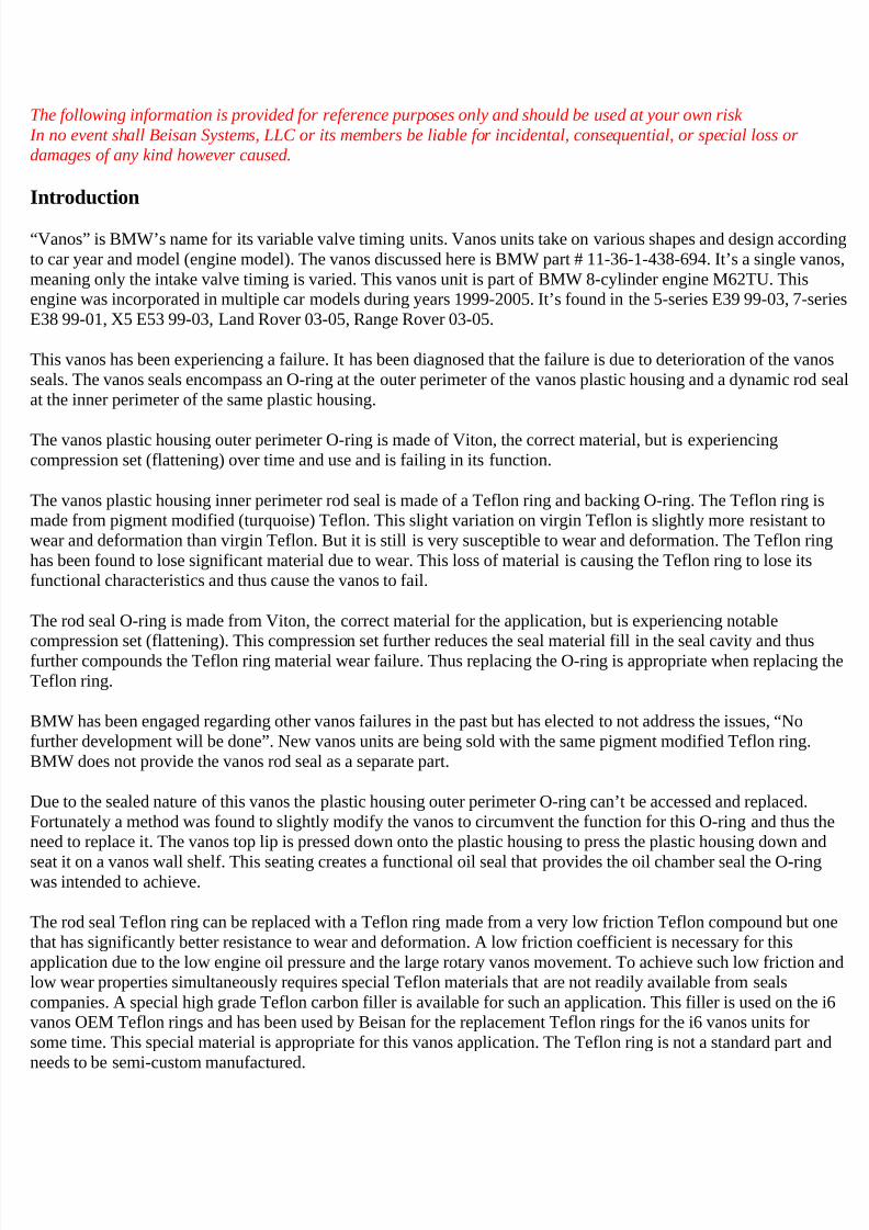
The following pictures show the vanos cut open and disassembled then piecemeal reassembled to show its parts.
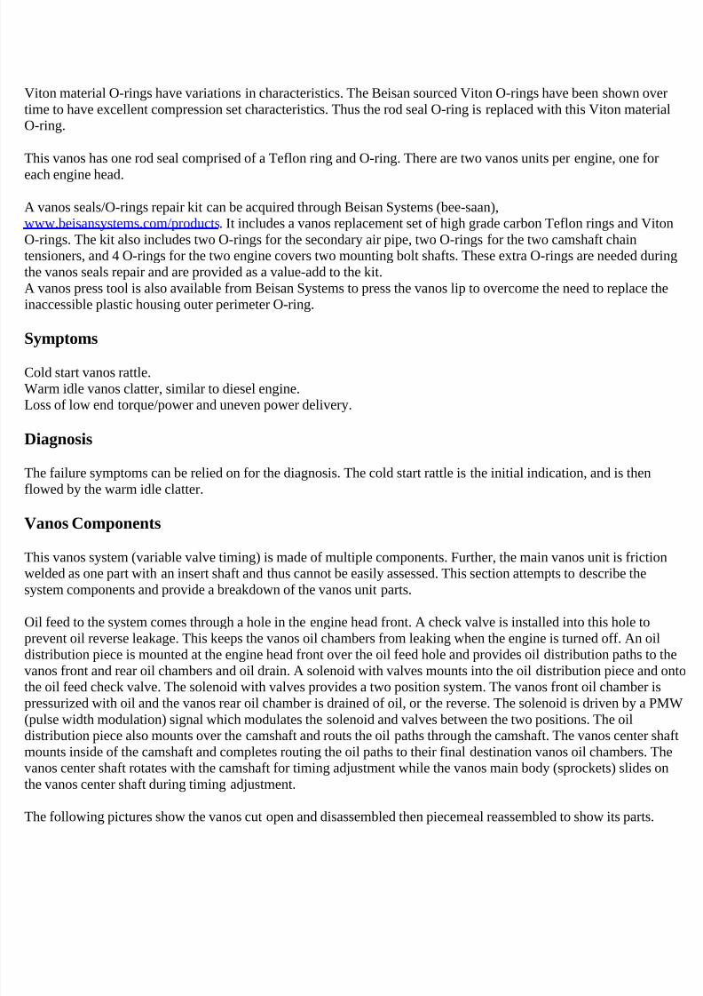
The vanos incorporates the intake camshaft sprockets.Internally it’s a cylinder with polished wall and a center cylinder shaft with helical gears on the outer diameter andpolished wall on the inner diameter.Holes in the cylinder shaft provide an oil path to the vanos rear oil chamber.A shelf on the cylinder inner wall provides a stop/seating position for the plastic housing (three pictures below).
7/29/2019 Removing and Cleaning a Mkiv Throttle Body
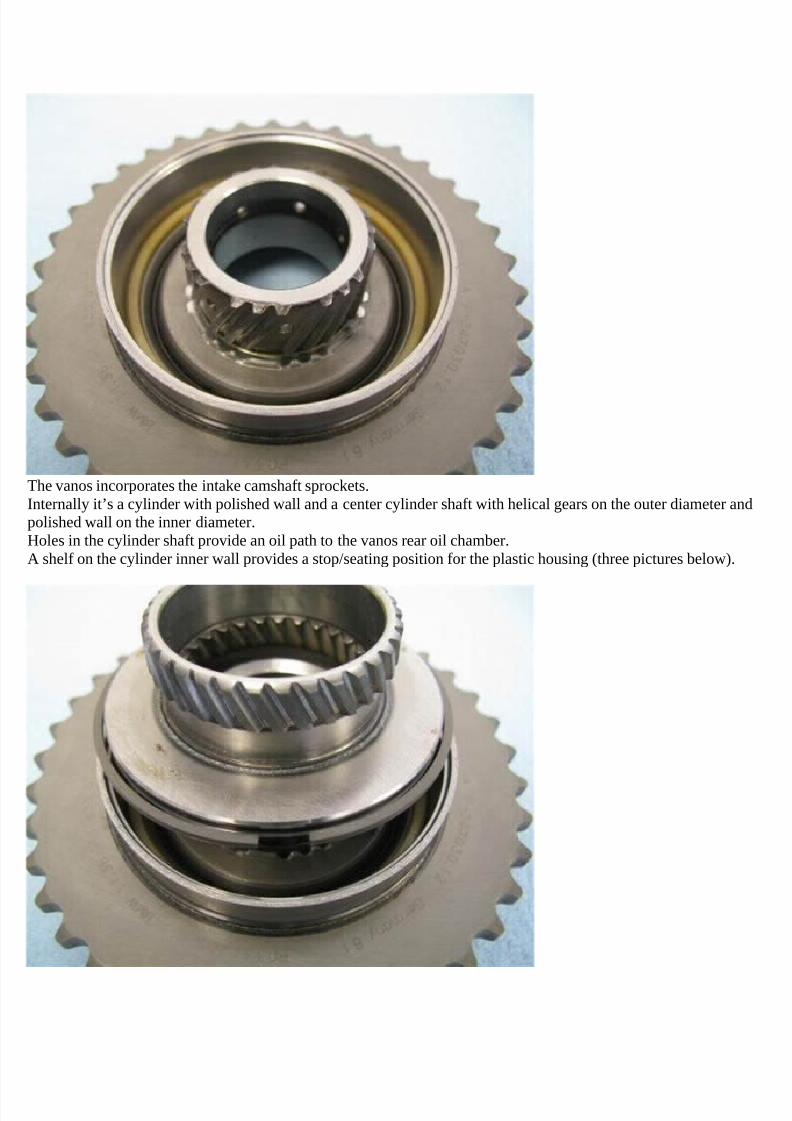
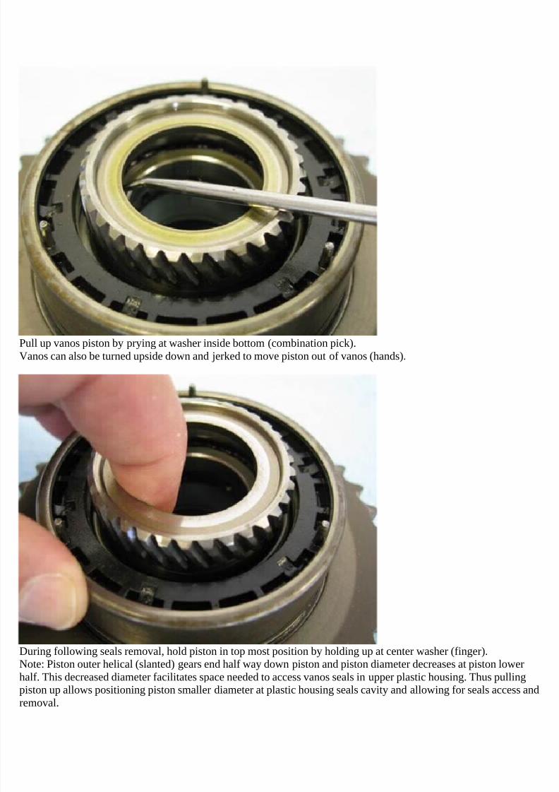
A piston with center cylinder shaft with helical gears on the inner and outer diameter inserts onto the vanos centercylinder shaft and mates the helical gears.A steel ring inserts into the piston outer perimeter groove and acts as a dynamic seal.The vanos body and piston create an oil chamber at the rear of the piston.
7/29/2019 Removing and Cleaning a Mkiv Throttle Body
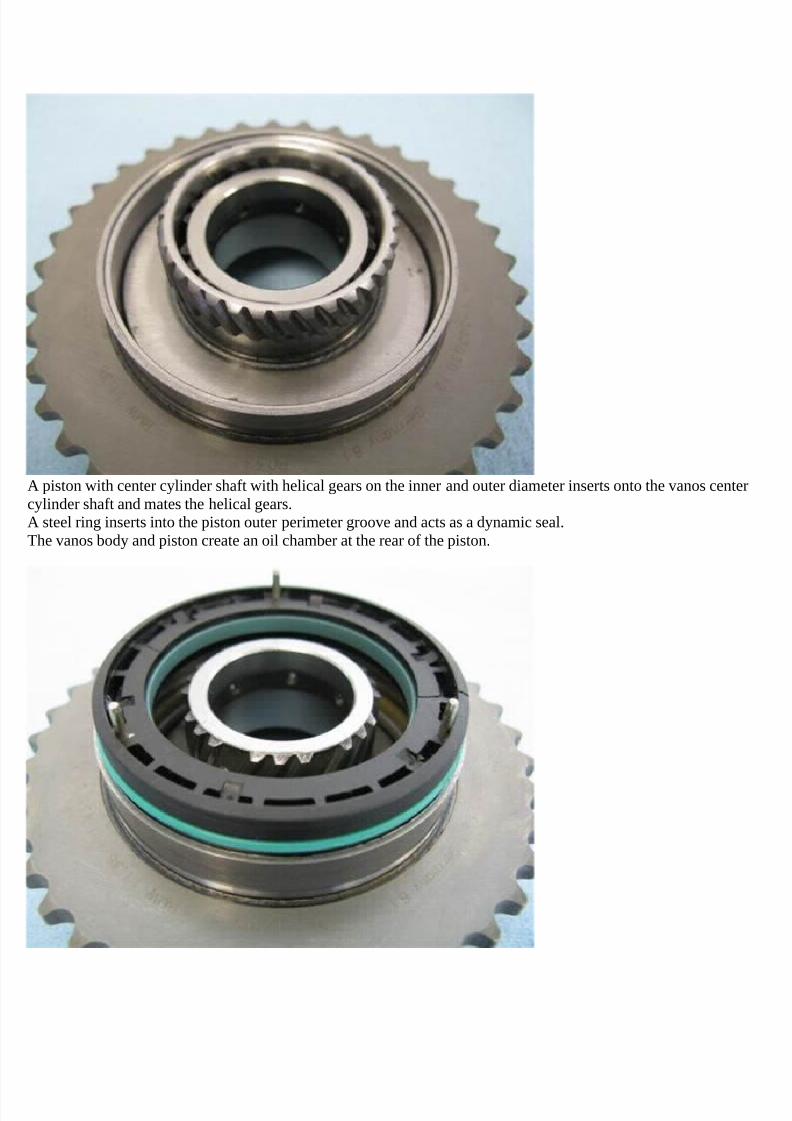
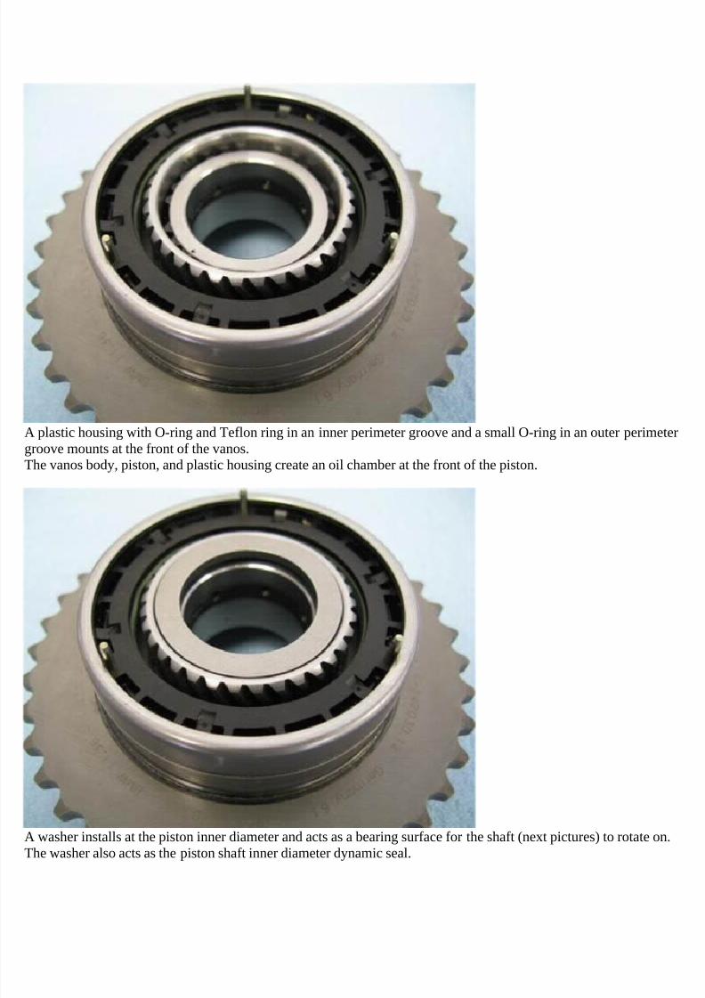
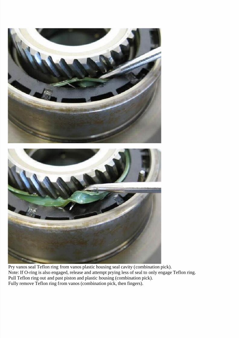
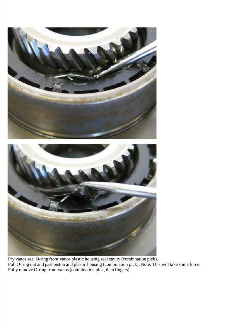
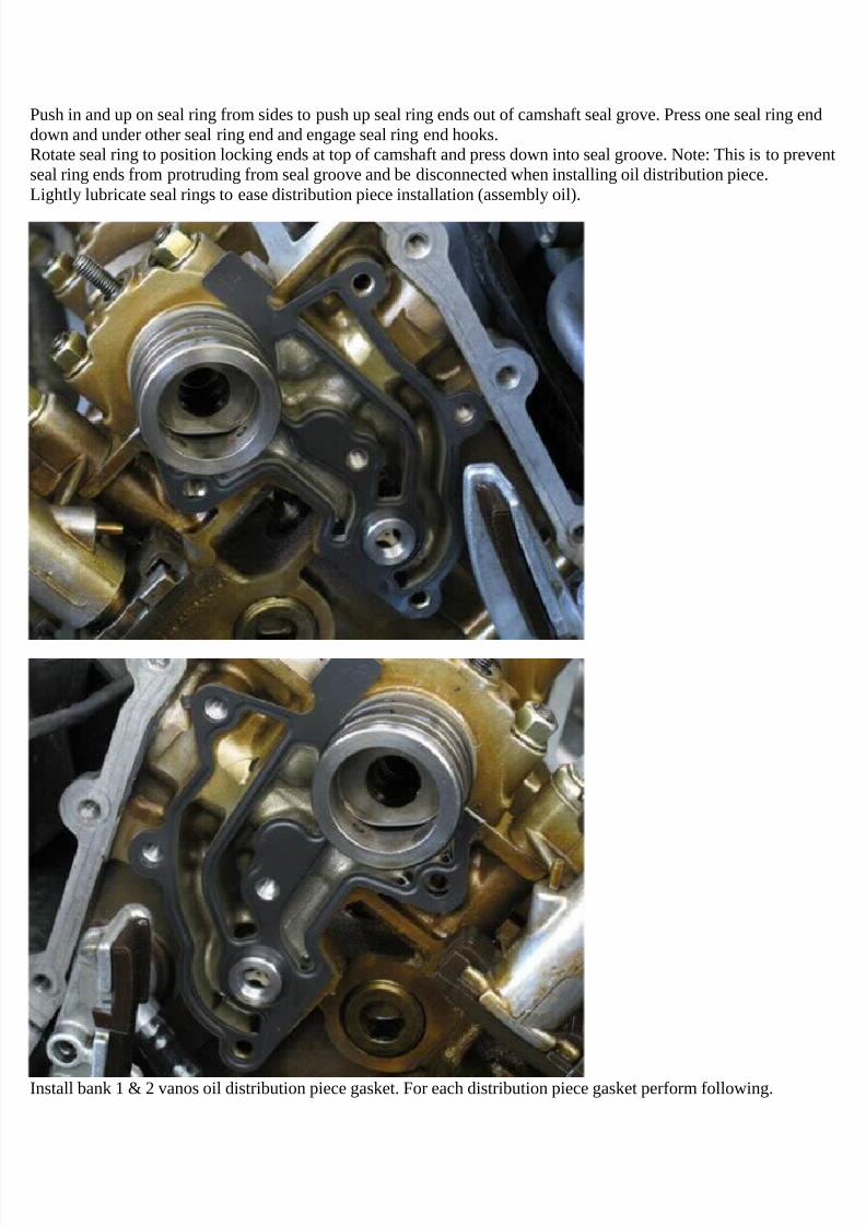
A plastic housing with O-ring and Teflon ring in an inner perimeter groove and a small O-ring in an outer perimetergroove mounts at the front of the vanos.The vanos body, piston, and plastic housing create an oil chamber at the front of the piston.
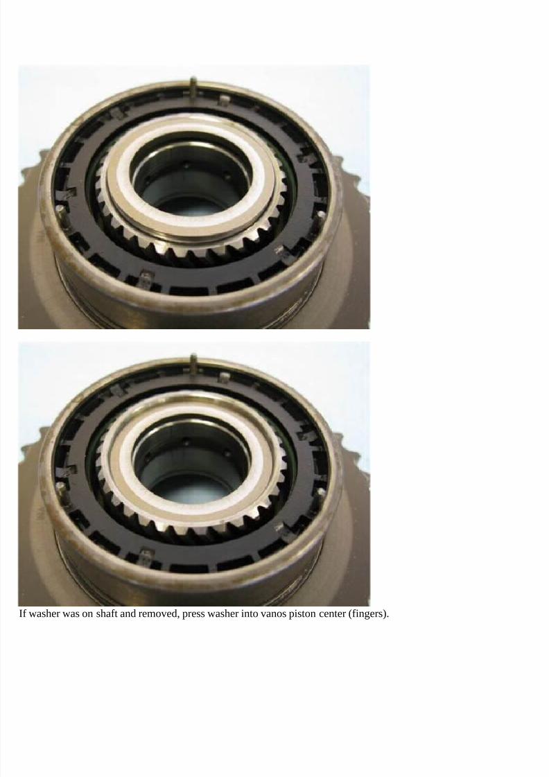
A washer installs at the piston inner diameter and acts as a bearing surface for the shaft (next pictures) to rotate on.The washer also acts as the piston shaft inner diameter dynamic seal.
7/29/2019 Removing and Cleaning a Mkiv Throttle Body
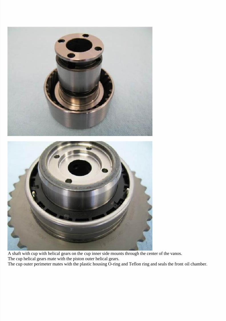
A shaft with cup with helical gears on the cup inner side mounts through the center of the vanos.The cup helical gears mate with the piston outer helical gears.The cup outer perimeter mates with the plastic housing O-ring and Teflon ring and seals the front oil chamber.
7/29/2019 Removing and Cleaning a Mkiv Throttle Body
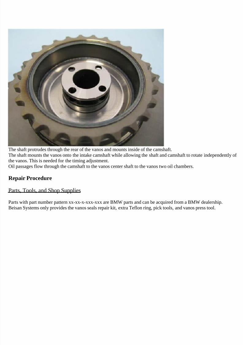
The shaft protrudes through the rear of the vanos and mounts inside of the camshaft.The shaft mounts the vanos onto the intake camshaft while allowing the shaft and camshaft to rotate independently ofthe vanos. This is needed for the timing adjustment.Oil passages flow through the camshaft to the vanos center shaft to the vanos two oil chambers.
Repair Procedure
Parts, Tools, and Shop Supplies
Parts with part number pattern xx-xx-x-xxx-xxx are BMW parts and can be acquired from a BMW dealership.Beisan Systems only provides the vanos seals repair kit, extra Teflon ring, pick tools, and vanos press tool.
7/29/2019 Removing and Cleaning a Mkiv Throttle Body
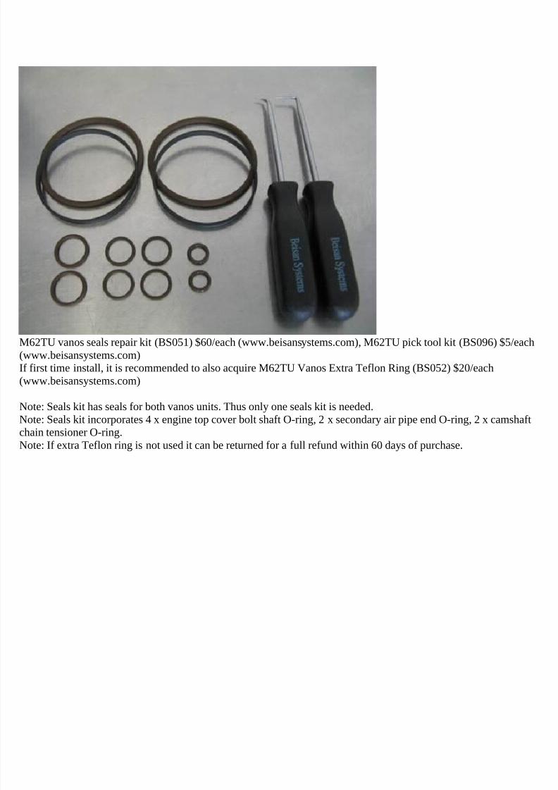
M62TU vanos seals repair kit (BS051) $60/each (www.beisansystems.com), M62TU pick tool kit (BS096) $5/each(www.beisansystems.com)If first time install, it is recommended to also acquire M62TU Vanos Extra Teflon Ring (BS052) $20/each(www.beisansystems.com)
Note: Seals kit has seals for both vanos units. Thus only one seals kit is needed.
Note: Seals kit incorporates 4 x engine top cover bolt shaft O-ring, 2 x secondary air pipe end O-ring, 2 x camshaftchain tensioner O-ring.Note: If extra Teflon ring is not used it can be returned for a full refund within 60 days of purchase.
7/29/2019 Removing and Cleaning a Mkiv Throttle Body
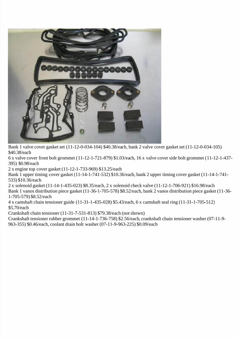
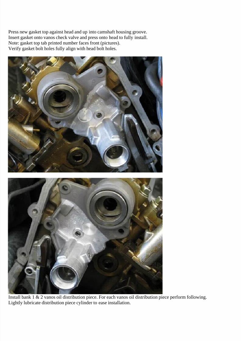
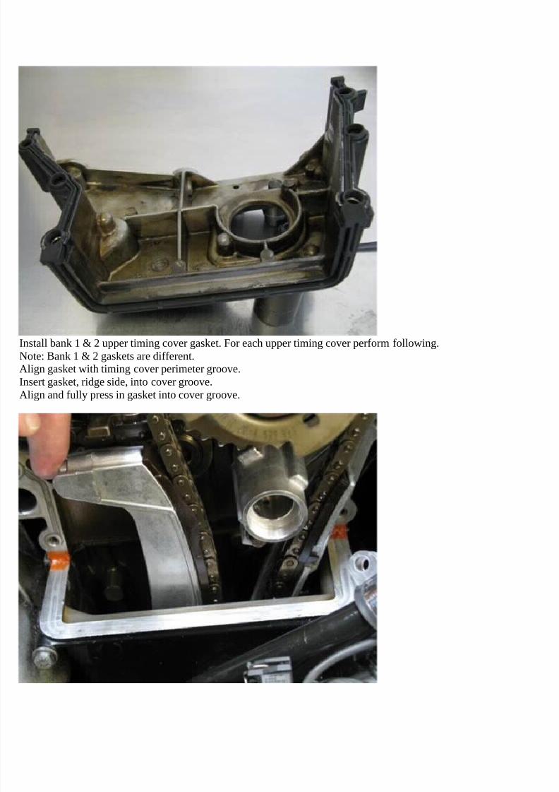
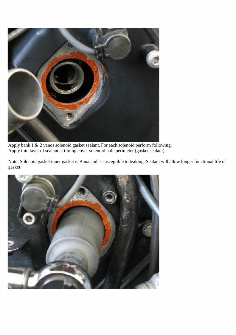
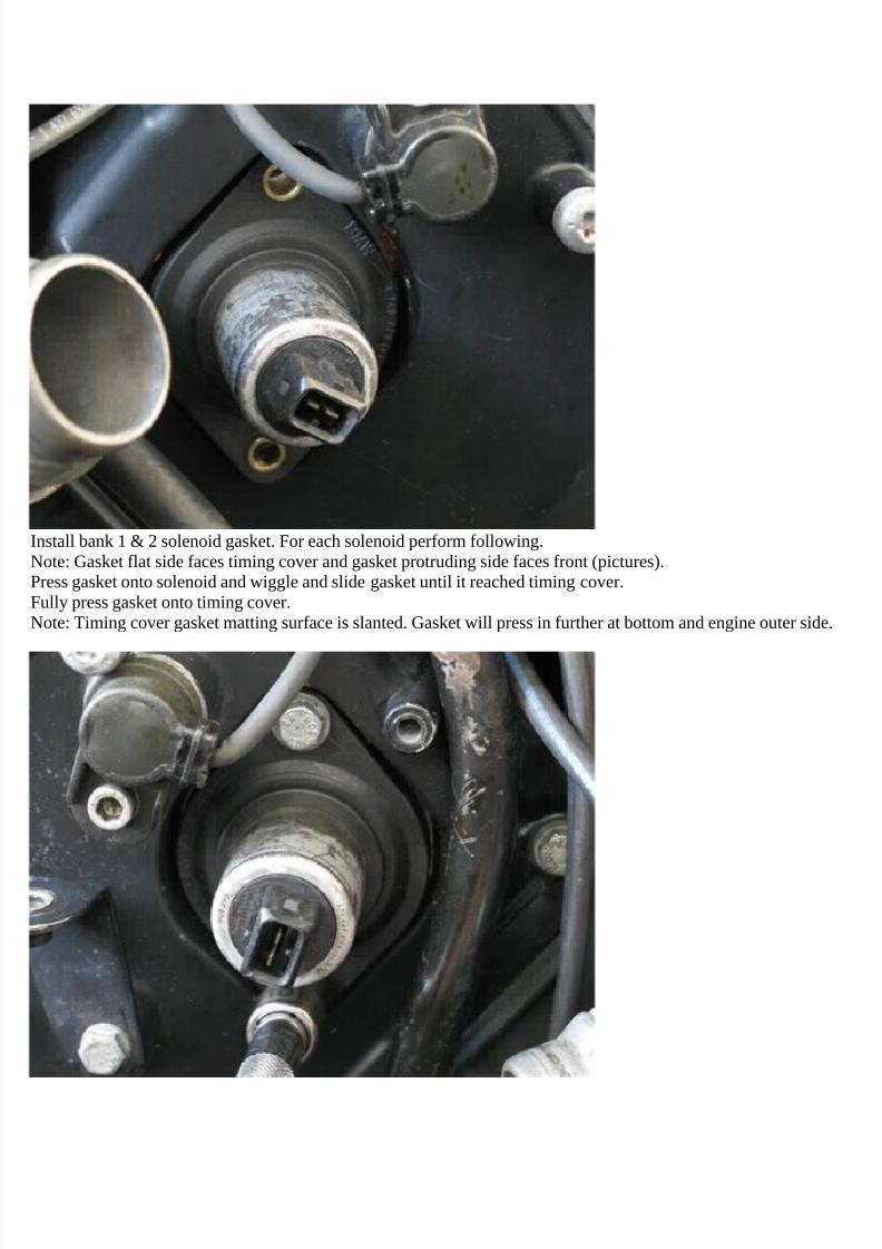
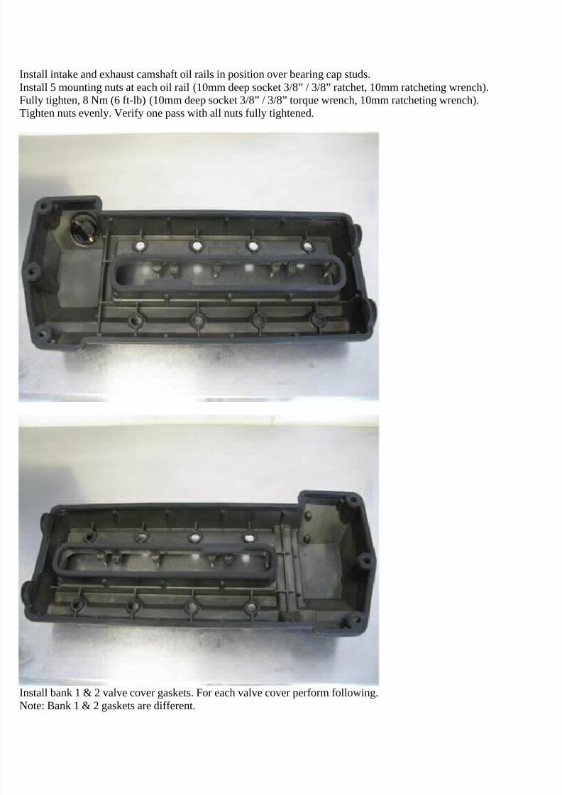
Bank 1 valve cover gasket set (11-12-0-034-104) $40.38/each, bank 2 valve cover gasket set (11-12-0-034-105)$40.38/each6 x valve cover front bolt grommet (11-12-1-721-879) $1.03/each, 16 x valve cover side bolt grommet (11-12-1-437-395) $0.98/each2 x engine top cover gasket (11-12-1-733-969) $13.25/eachBank 1 upper timing cover gasket (11-14-1-741-532) $10.36/each, bank 2 upper timing cover gasket (11-14-1-741-
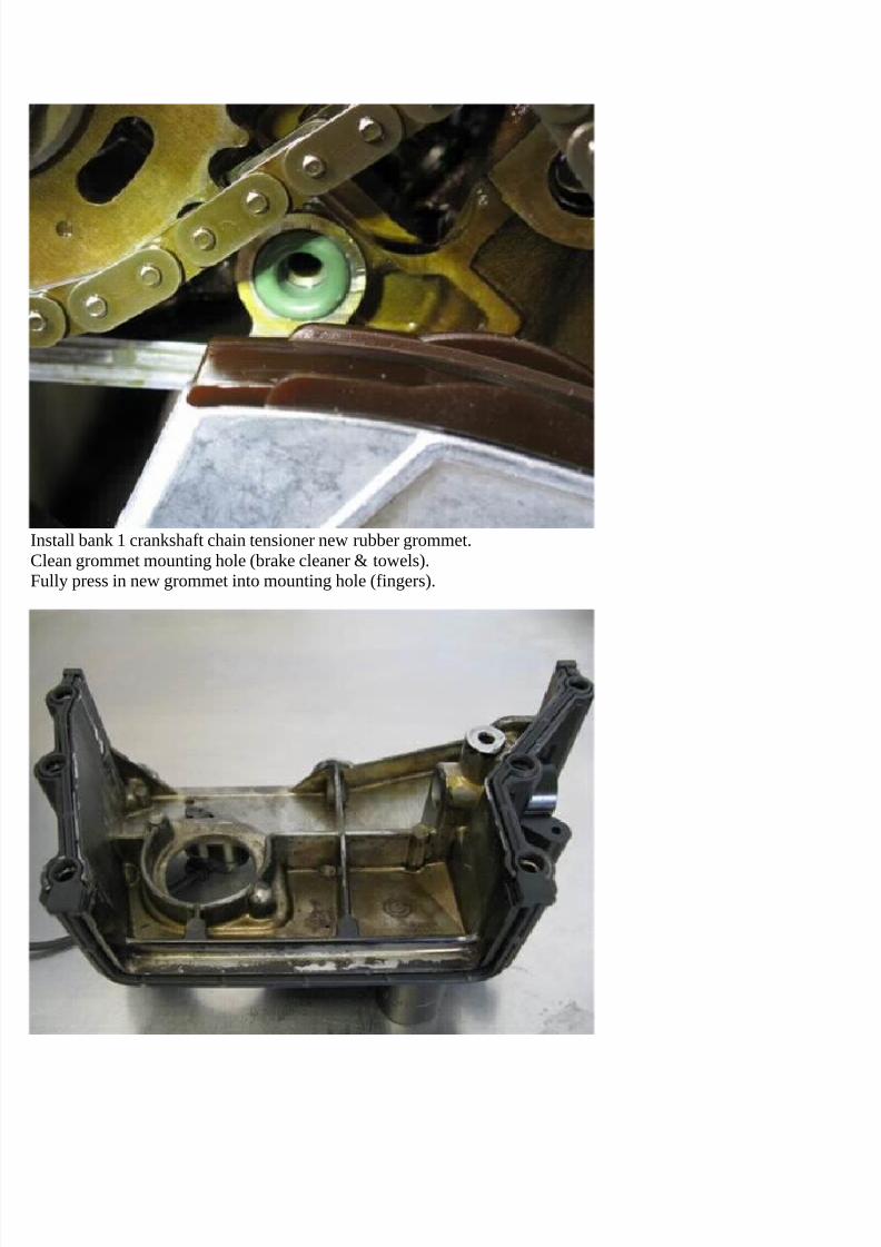
533) $10.36/each2 x solenoid gasket (11-14-1-435-023) $8.35/each, 2 x solenoid check valve (11-12-1-706-921) $16.98/eachBank 1 vanos distribution piece gasket (11-36-1-705-578) $8.52/each, bank 2 vanos distribution piece gasket (11-36-1-705-579) $8.52/each4 x camshaft chain tensioner guide (11-31-1-435-028) $5.43/each, 6 x camshaft seal ring (11-31-1-705-512)$5.70/eachCrankshaft chain tensioner (11-31-7-531-813) $79.38/each (not shown)Crankshaft tensioner rubber grommet (11-14-1-736-758) $2.56/each, crankshaft chain tensioner washer (07-11-9-963-355) $0.46/each, coolant drain bolt washer (07-11-9-963-225) $0.09/each
7/29/2019 Removing and Cleaning a Mkiv Throttle Body
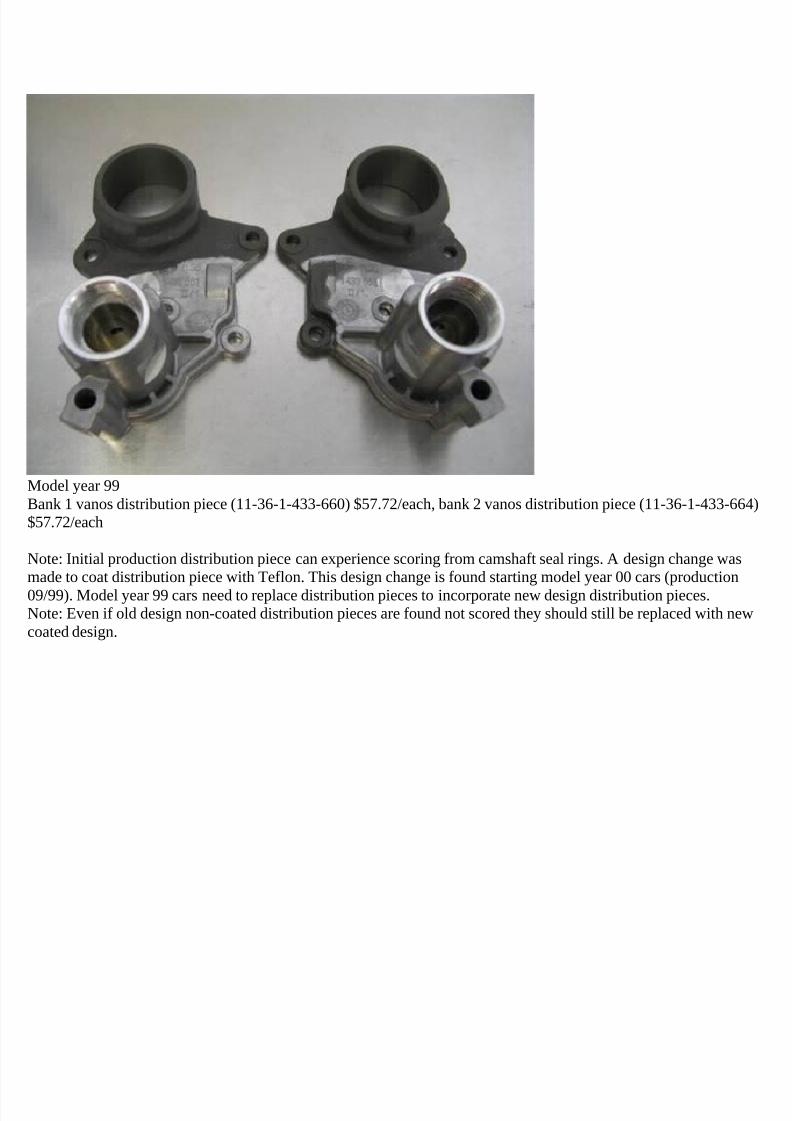
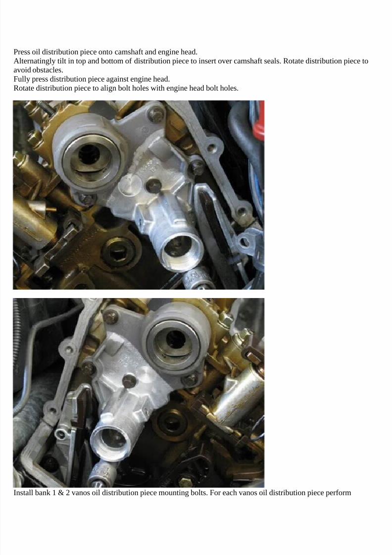
Model year 99Bank 1 vanos distribution piece (11-36-1-433-660) $57.72/each, bank 2 vanos distribution piece (11-36-1-433-664)$57.72/each
Note: Initial production distribution piece can experience scoring from camshaft seal rings. A design change wasmade to coat distribution piece with Teflon. This design change is found starting model year 00 cars (production
09/99). Model year 99 cars need to replace distribution pieces to incorporate new design distribution pieces.Note: Even if old design non-coated distribution pieces are found not scored they should still be replaced with newcoated design.
7/29/2019 Removing and Cleaning a Mkiv Throttle Body
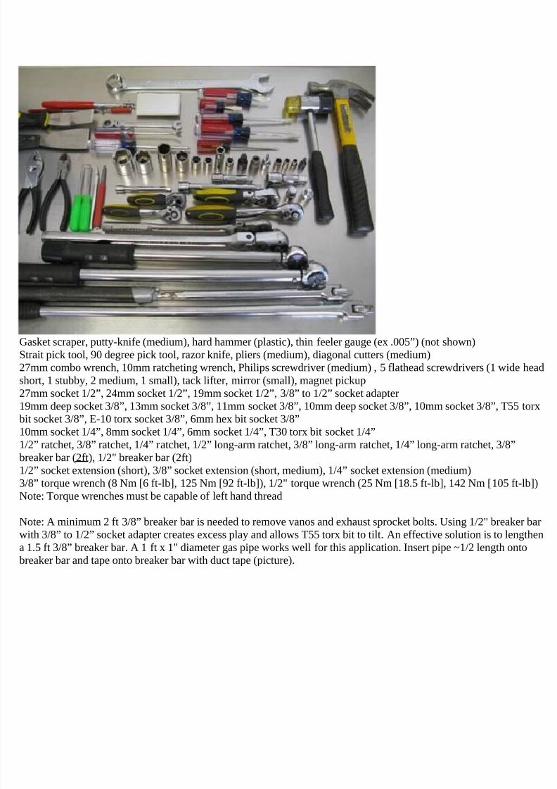
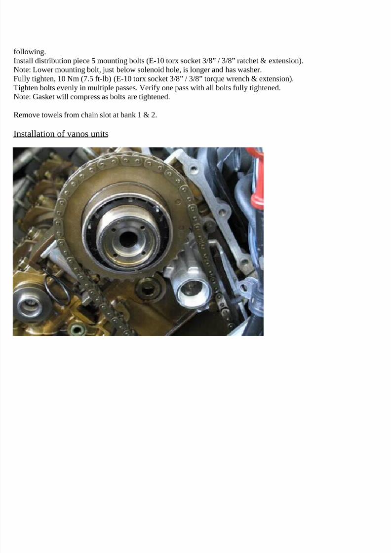
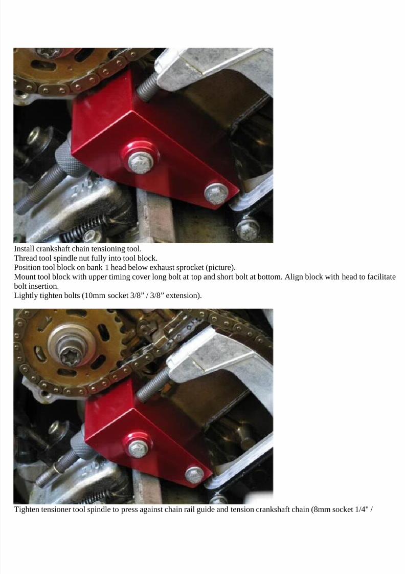
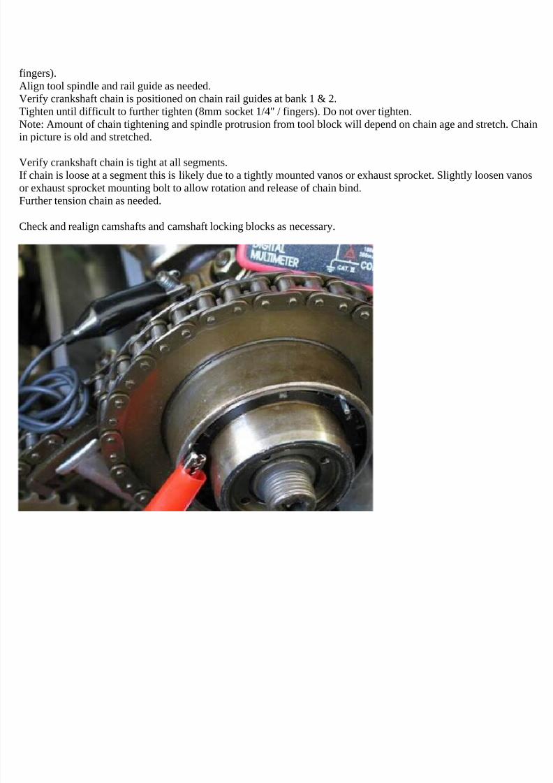
bit socket 3/8”, E-10 torx socket 3/8”, 6mm hex bit socket 3/8”10mm socket 1/4”, 8mm socket 1/4”, 6mm socket 1/4”, T30 torx bit socket 1/4”1/2” ratchet, 3/8” ratchet, 1/4” ratchet, 1/2” long-arm ratchet, 3/8” long-arm ratchet, 1/4” long-arm ratchet, 3/8”breaker bar (2ft), 1/2" breaker bar (2ft)1/2” socket extension (short), 3/8” socket extension (short, medium), 1/4” socket extension (medium)3/8” torque wrench (8 Nm [6 ft-lb], 125 Nm [92 ft-lb]), 1/2" torque wrench (25 Nm [18.5 ft-lb], 142 Nm [105 ft-lb])Note: Torque wrenches must be capable of left hand thread
Note: A minimum 2 ft 3/8” breaker bar is needed to remove vanos and exhaust sprocket bolts. Using 1/2" breaker barwith 3/8” to 1/2” socket adapter creates excess play and allows T55 torx bit to tilt. An effective solution is to lengthen
a 1.5 ft 3/8” breaker bar. A 1 ft x 1" diameter gas pipe works well for this application. Insert pipe ~1/2 length ontobreaker bar and tape onto breaker bar with duct tape (picture).
7/29/2019 Removing and Cleaning a Mkiv Throttle Body
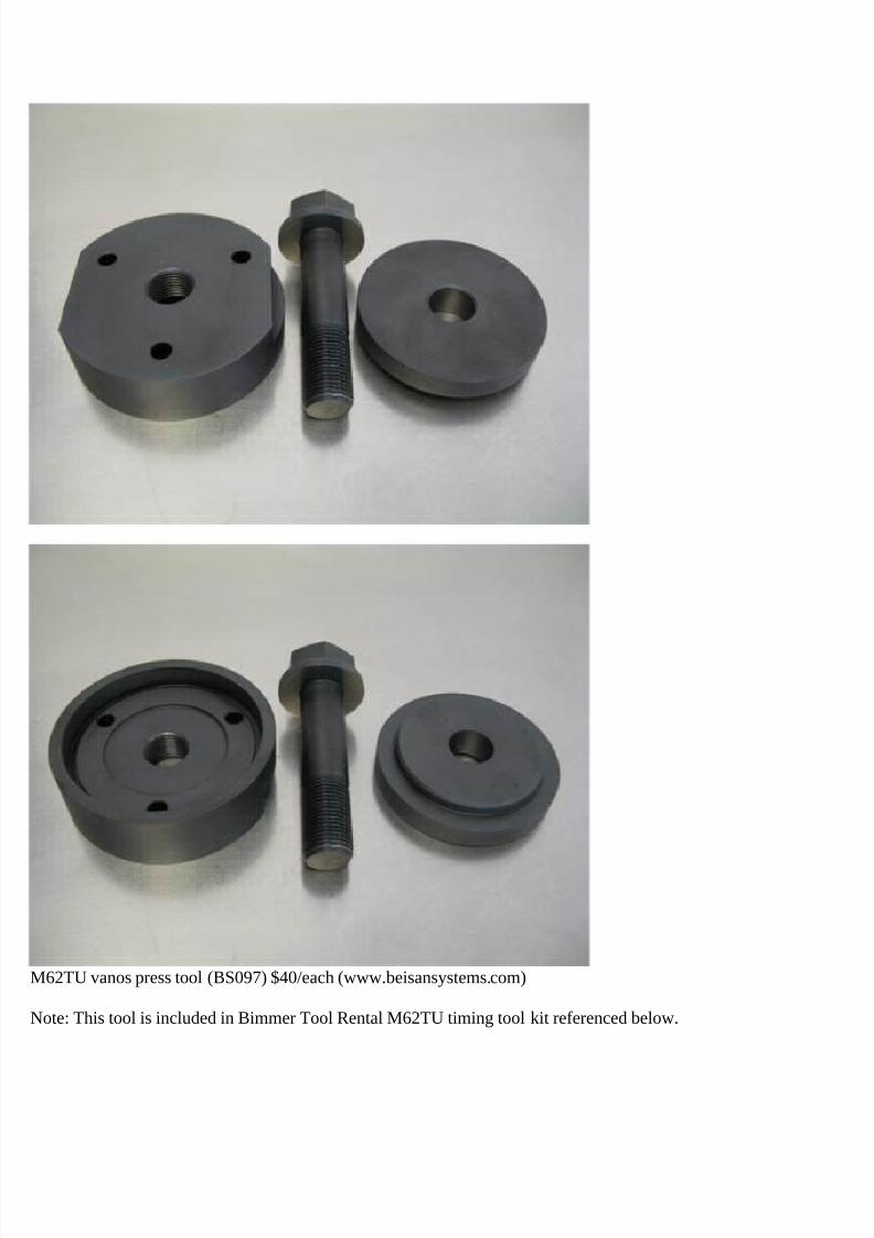
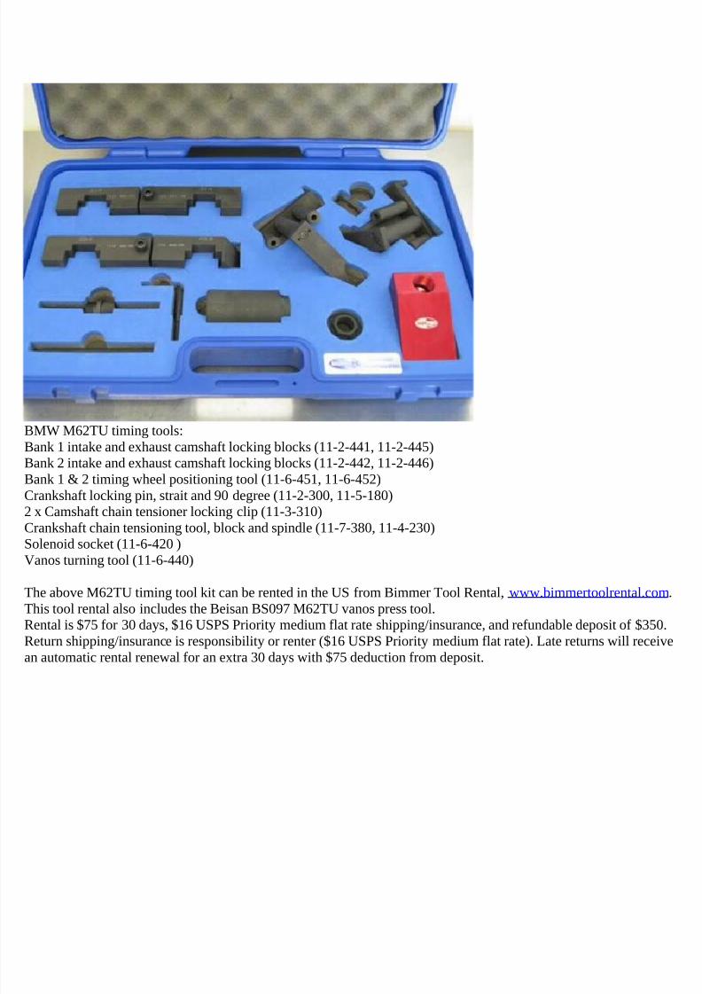
The above M62TU timing tool kit can be rented in the US from Bimmer Tool Rental, www.bimmertoolrental.com.This tool rental also includes the Beisan BS097 M62TU vanos press tool.Rental is $75 for 30 days, $16 USPS Priority medium flat rate shipping/insurance, and refundable deposit of $350.Return shipping/insurance is responsibility or renter ($16 USPS Priority medium flat rate). Late returns will receivean automatic rental renewal for an extra 30 days with $75 deduction from deposit.
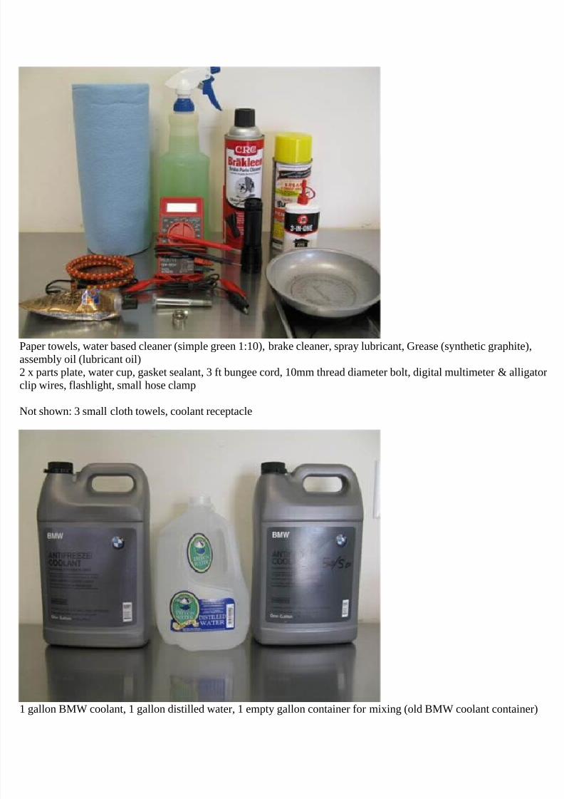
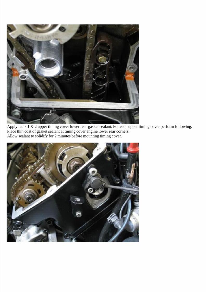
Paper towels, water based cleaner (simple green 1:10), brake cleaner, spray lubricant, Grease (synthetic graphite),assembly oil (lubricant oil)2 x parts plate, water cup, gasket sealant, 3 ft bungee cord, 10mm thread diameter bolt, digital multimeter & alligatorclip wires, flashlight, small hose clamp
Not shown: 3 small cloth towels, coolant receptacle
1 gallon BMW coolant, 1 gallon distilled water, 1 empty gallon container for mixing (old BMW coolant container)
7/29/2019 Removing and Cleaning a Mkiv Throttle Body
Car engine must be cold to perform repair procedure.
Right and Left denotations are from car front at hood orientation.
Engine bank 1 head is on left and engine bank 2 head is on right.Cylinders 1-4 are on bank 1 front to rear, and cylinders 5-8 are on bank 2 front to rear.
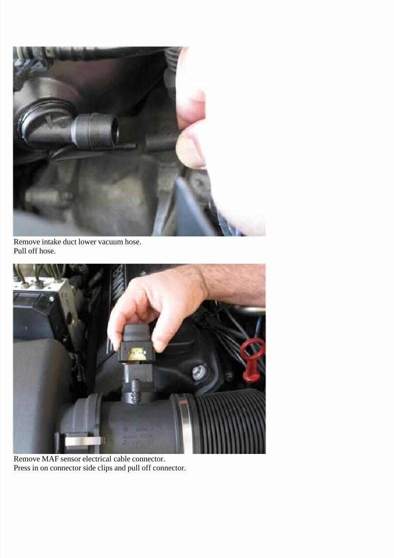
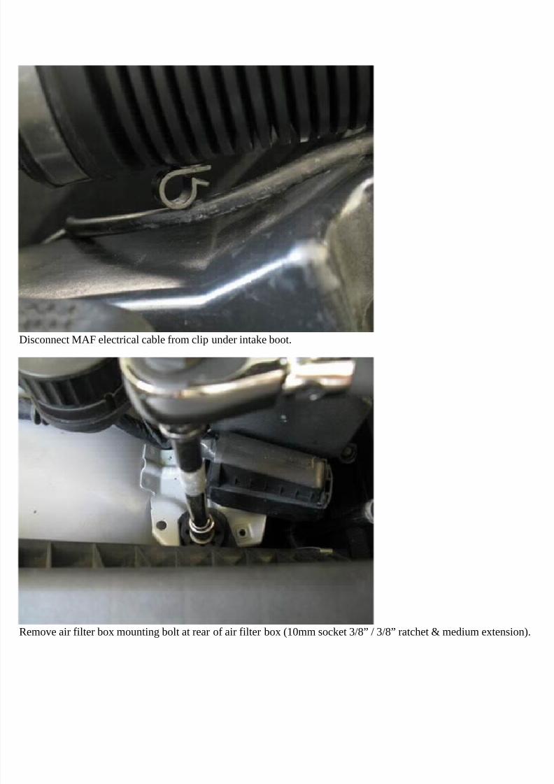
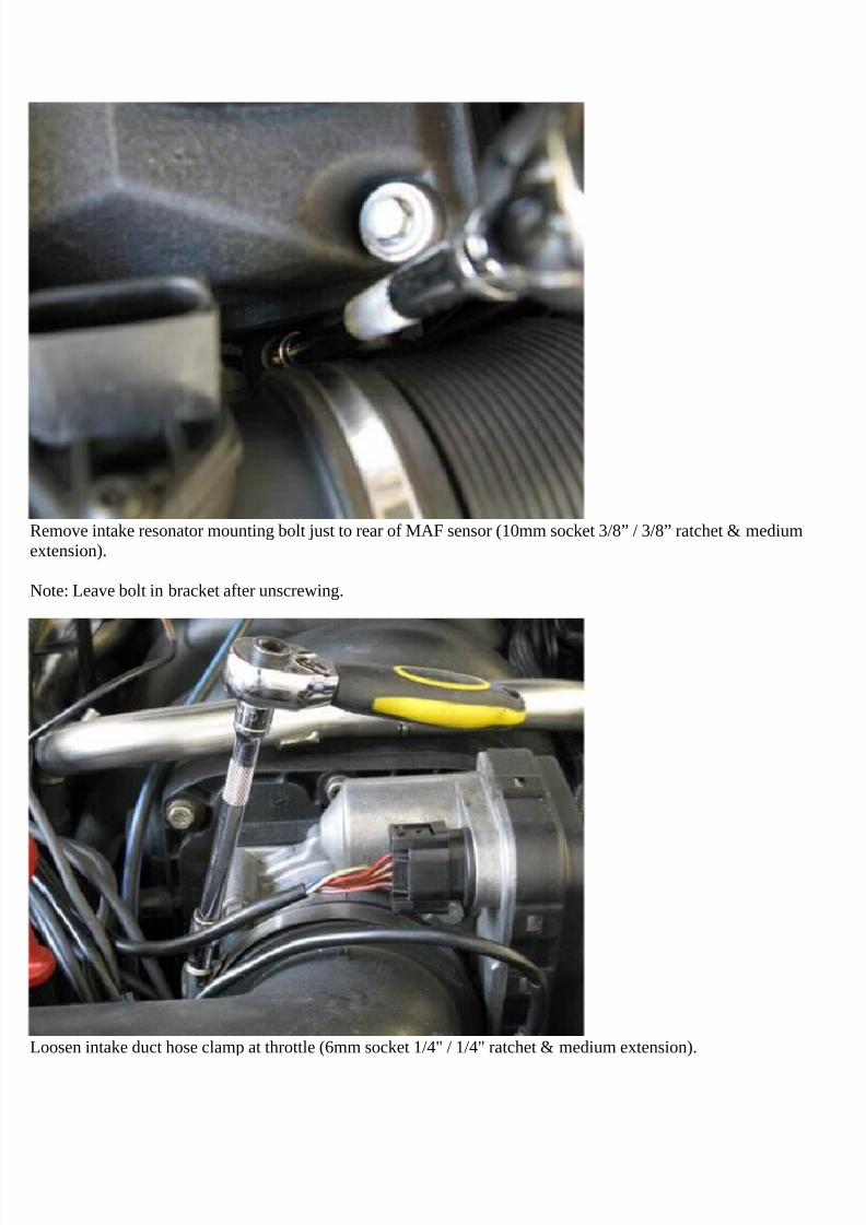
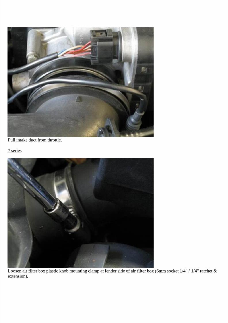
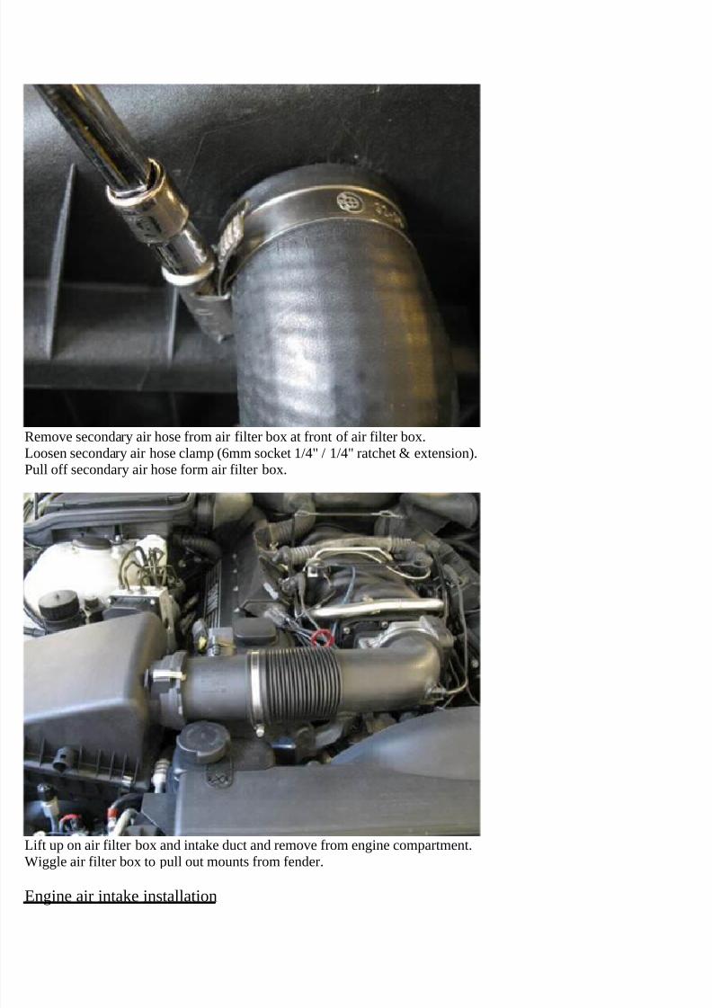
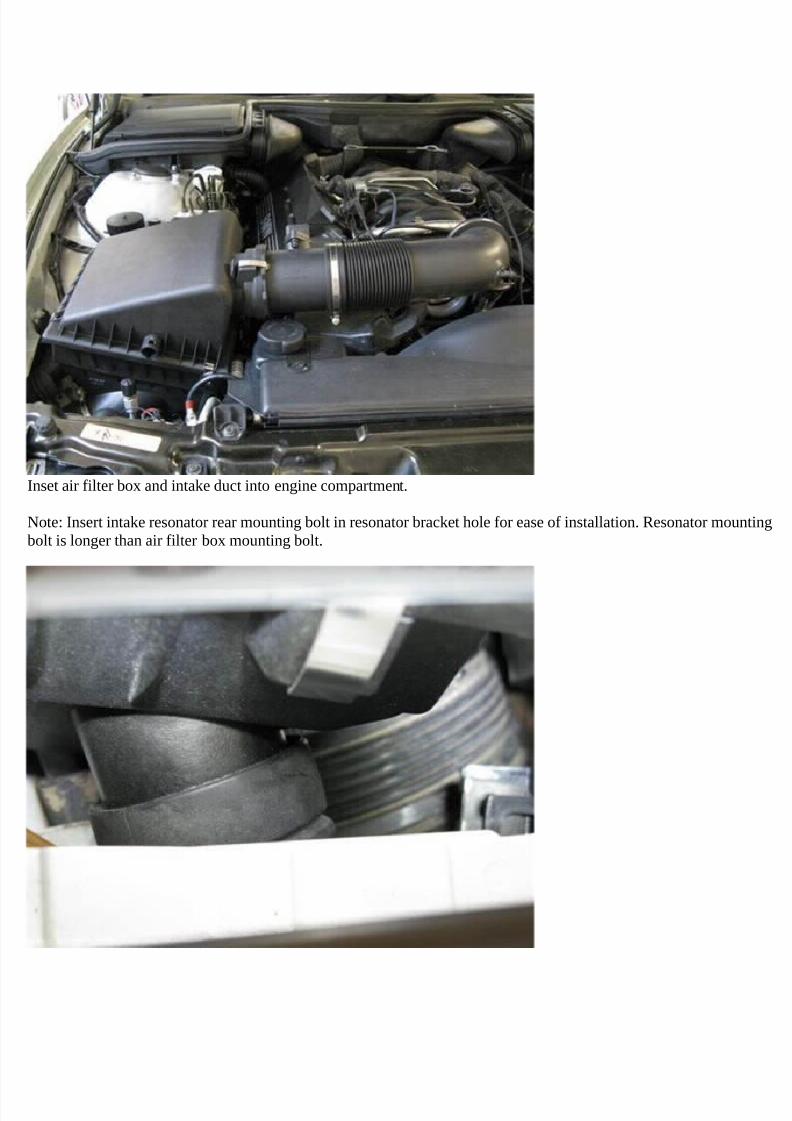
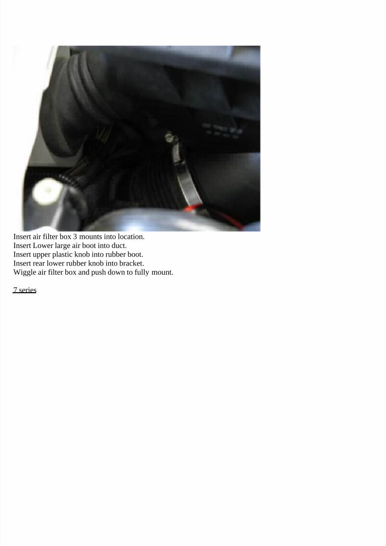
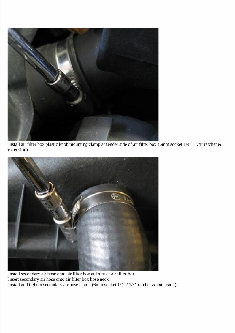
Removal of engine air intake
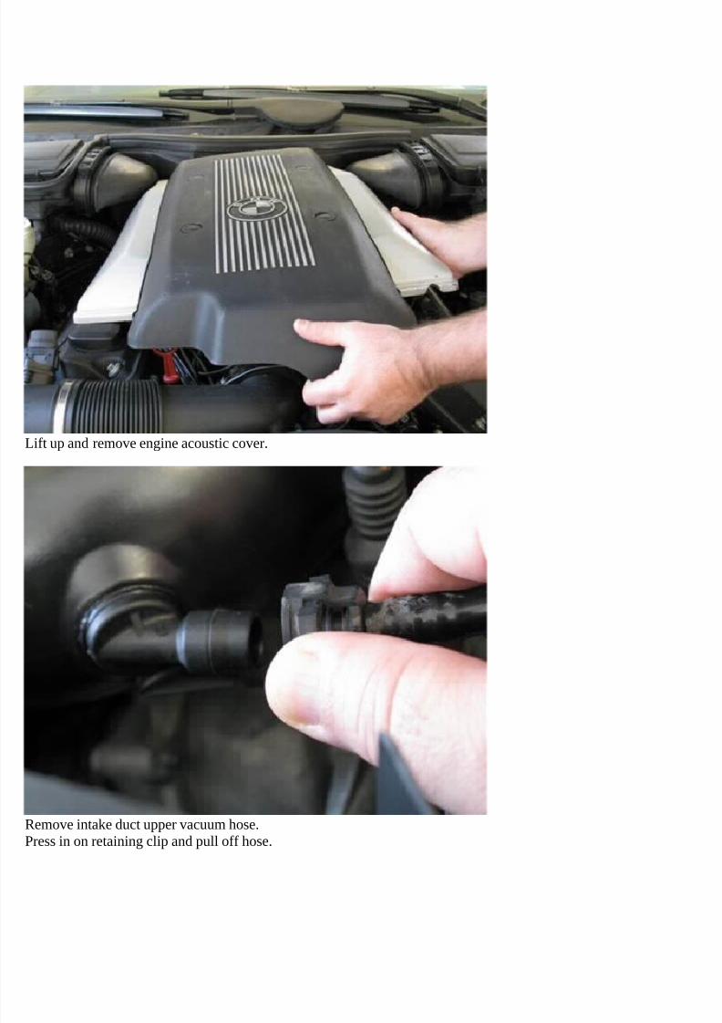
Engine air intake removal
Removal of fan & shroud
Fan & shroud removal
Removal of cabin filter housing
E39 cabin filter housing removal
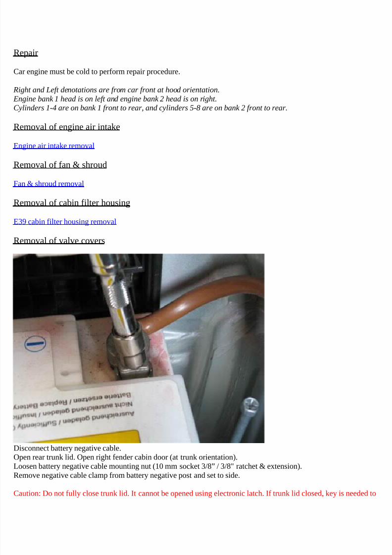
Removal of valve covers
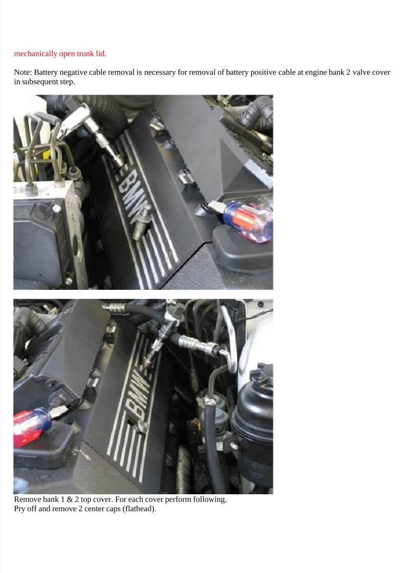
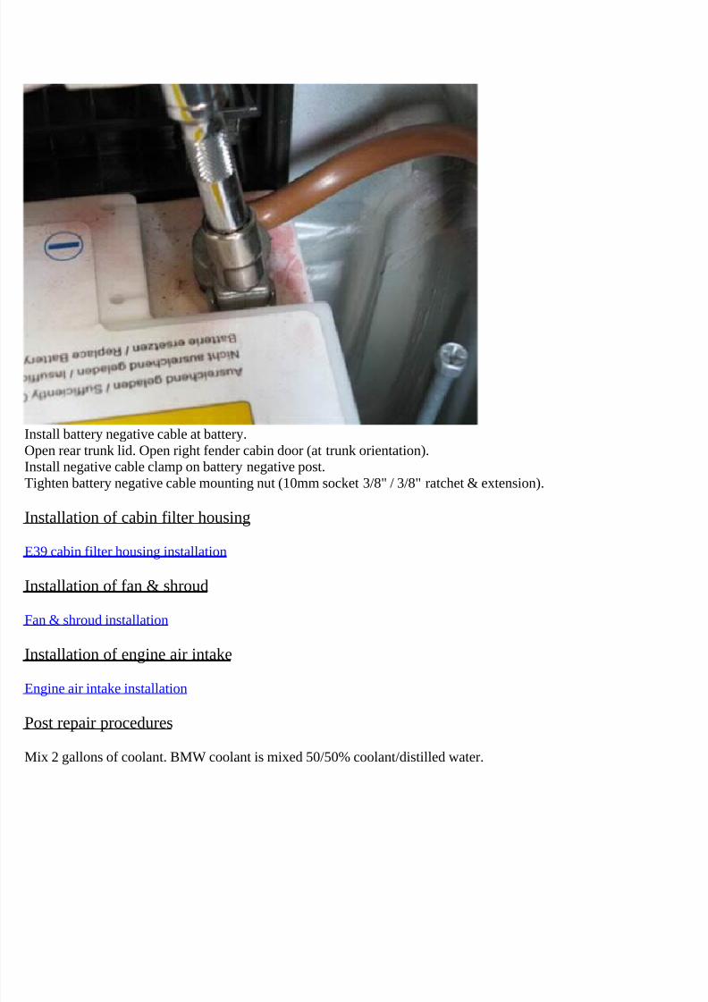
Disconnect battery negative cable.Open rear trunk lid. Open right fender cabin door (at trunk orientation).Loosen battery negative cable mounting nut (10 mm socket 3/8” / 3/8" ratchet & extension).Remove negative cable clamp from battery negative post and set to side.
Caution: Do not fully close trunk lid. It cannot be opened using electronic latch. If trunk lid closed, key is needed to
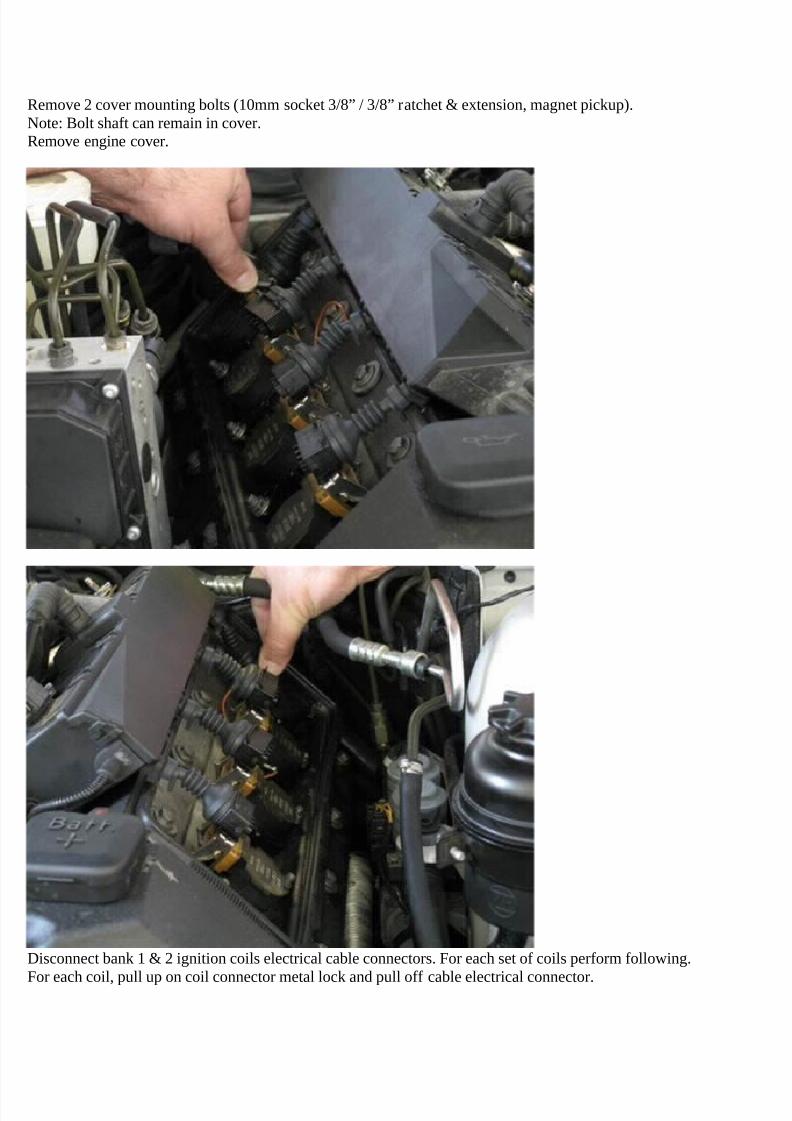
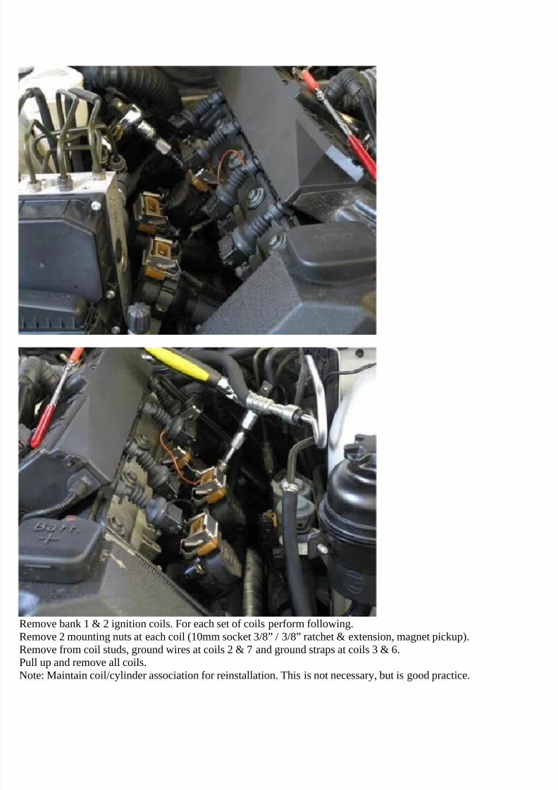
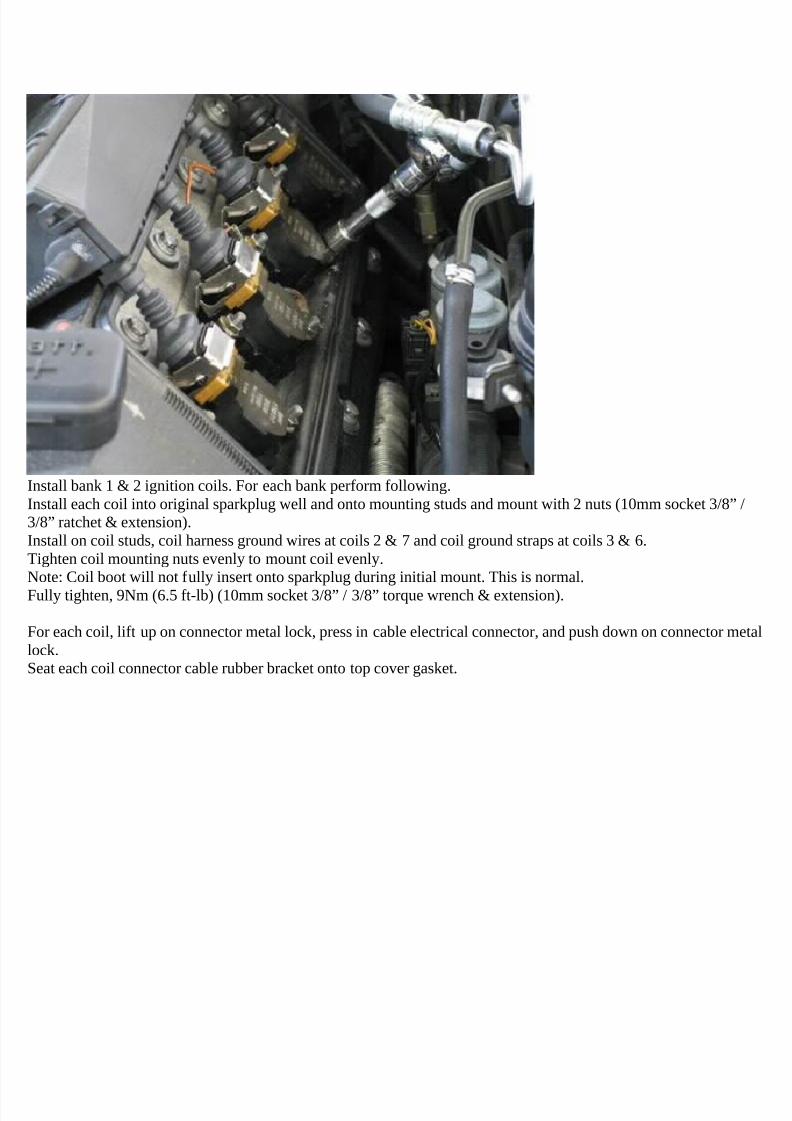
Remove bank 1 & 2 ignition coils. For each set of coils perform following.Remove 2 mounting nuts at each coil (10mm socket 3/8” / 3/8” ratchet & extension, magnet pickup).Remove from coil studs, ground wires at coils 2 & 7 and ground straps at coils 3 & 6.Pull up and remove all coils.Note: Maintain coil/cylinder association for reinstallation. This is not necessary, but is good practice.
7/29/2019 Removing and Cleaning a Mkiv Throttle Body
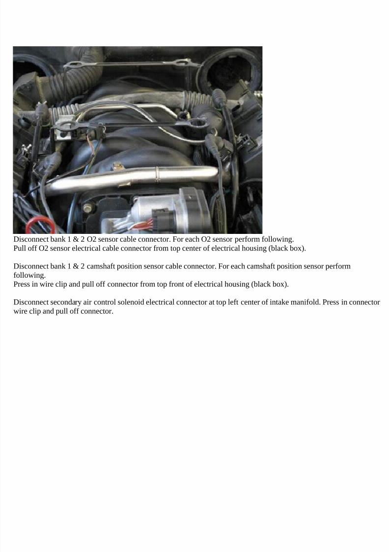
Disconnect bank 1 & 2 O2 sensor cable connector. For each O2 sensor perform following.Pull off O2 sensor electrical cable connector from top center of electrical housing (black box).
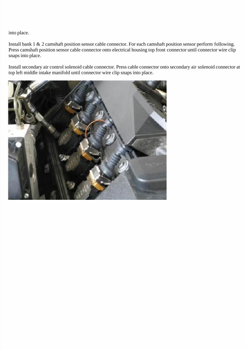
Disconnect bank 1 & 2 camshaft position sensor cable connector. For each camshaft position sensor performfollowing.Press in wire clip and pull off connector from top front of electrical housing (black box).
Disconnect secondary air control solenoid electrical connector at top left center of intake manifold. Press in connectorwire clip and pull off connector.
7/29/2019 Removing and Cleaning a Mkiv Throttle Body
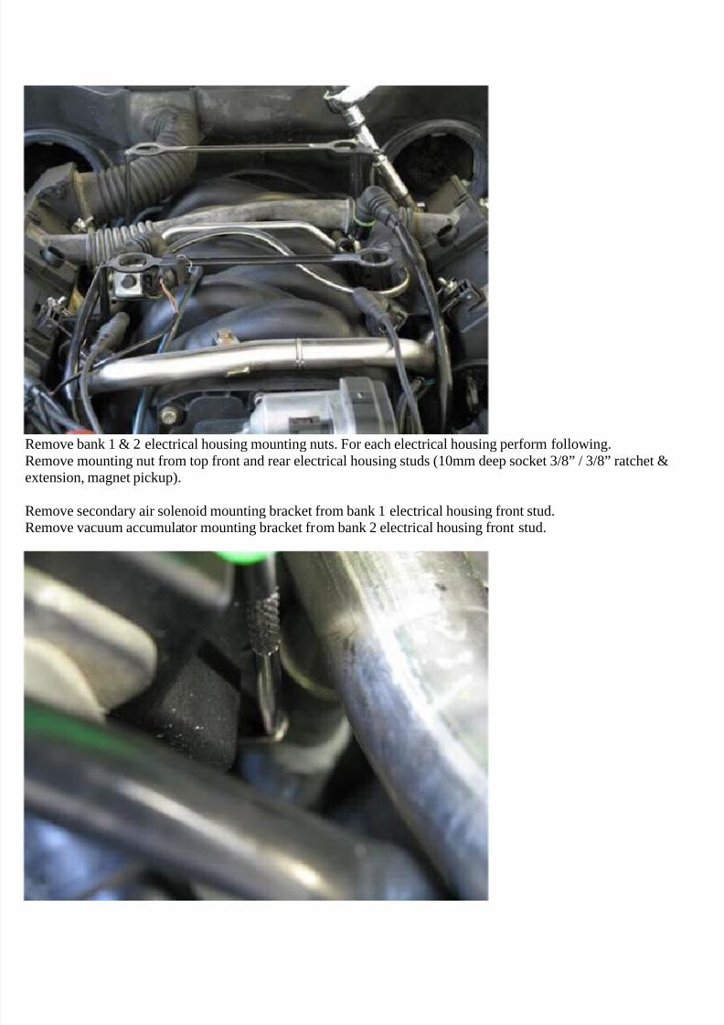
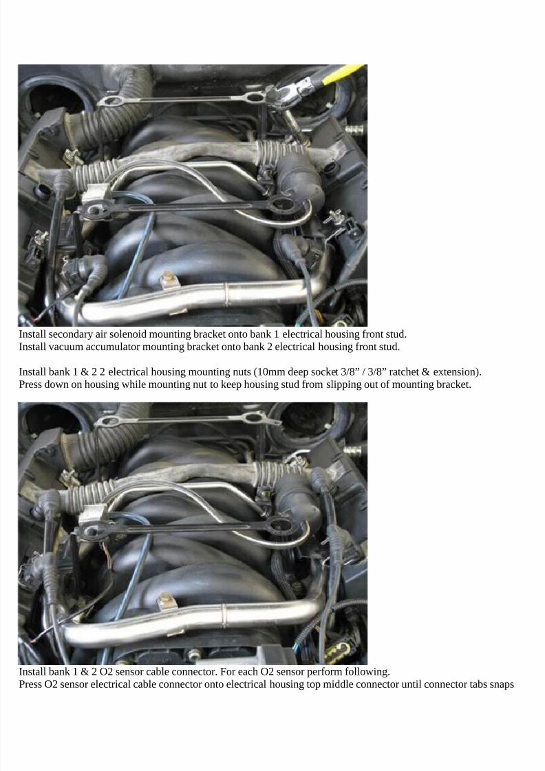
Remove bank 1 & 2 electrical housing mounting nuts. For each electrical housing perform following.Remove mounting nut from top front and rear electrical housing studs (10mm deep socket 3/8” / 3/8” ratchet &extension, magnet pickup).
Remove secondary air solenoid mounting bracket from bank 1 electrical housing front stud.Remove vacuum accumulator mounting bracket from bank 2 electrical housing front stud.
7/29/2019 Removing and Cleaning a Mkiv Throttle Body
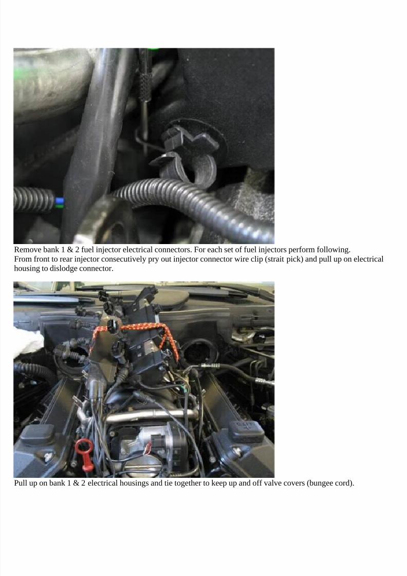
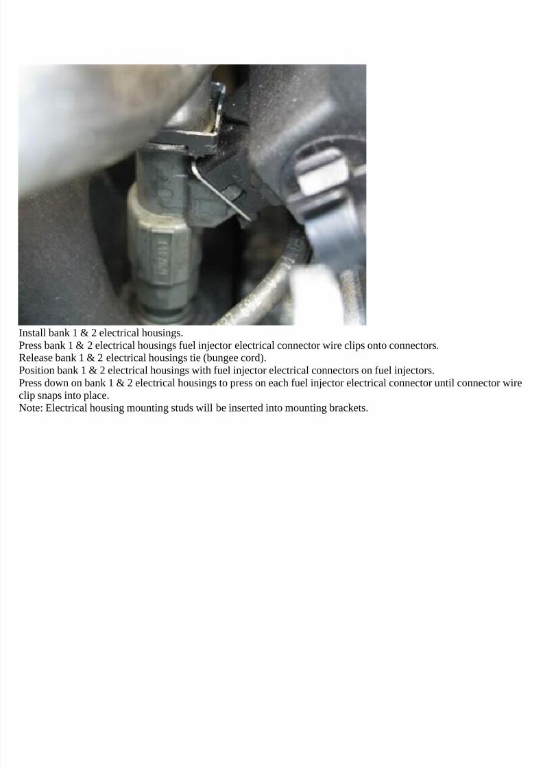
Remove bank 1 & 2 fuel injector electrical connectors. For each set of fuel injectors perform following.From front to rear injector consecutively pry out injector connector wire clip (strait pick) and pull up on electricalhousing to dislodge connector.
Pull up on bank 1 & 2 electrical housings and tie together to keep up and off valve covers (bungee cord).
7/29/2019 Removing and Cleaning a Mkiv Throttle Body
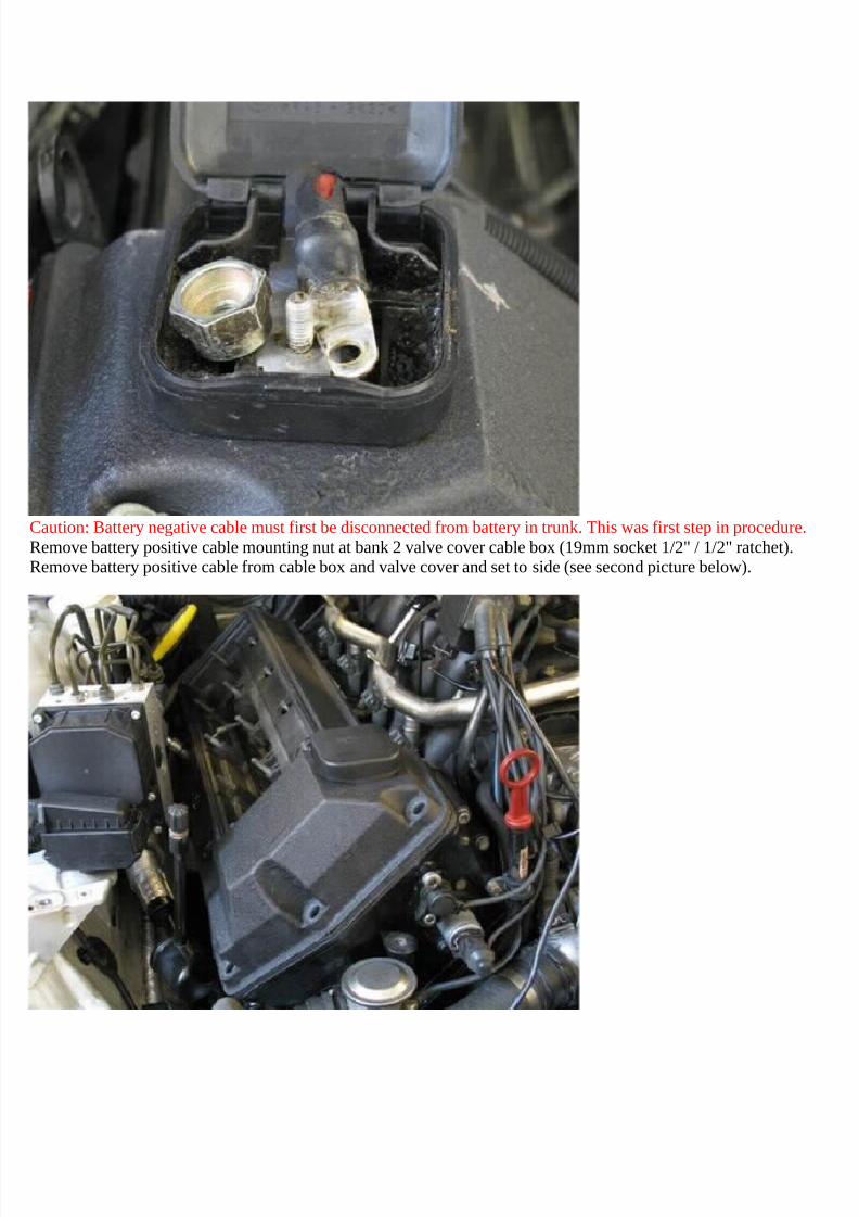
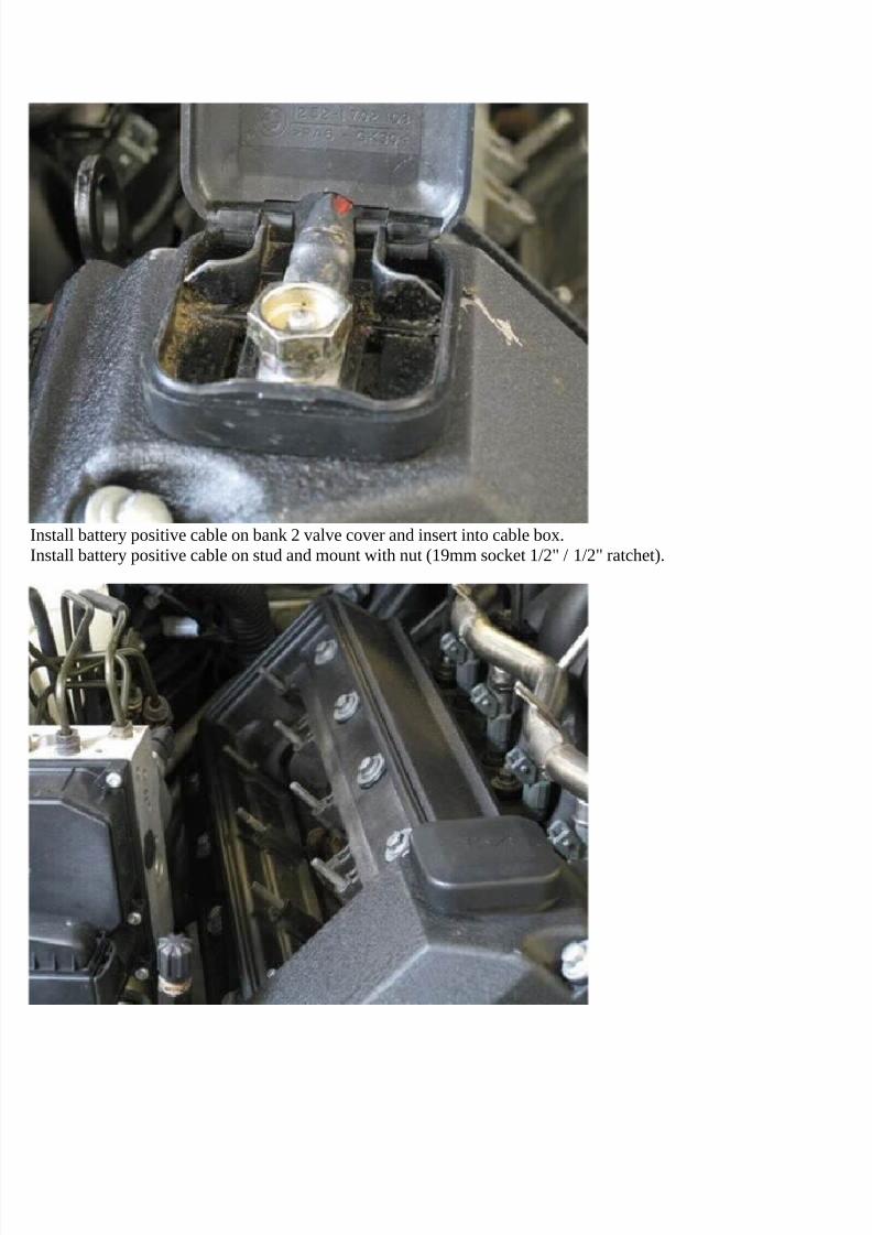
Caution: Battery negative cable must first be disconnected from battery in trunk. This was first step in procedure.Remove battery positive cable mounting nut at bank 2 valve cover cable box (19mm socket 1/2" / 1/2" ratchet).Remove battery positive cable from cable box and valve cover and set to side (see second picture below).
7/29/2019 Removing and Cleaning a Mkiv Throttle Body
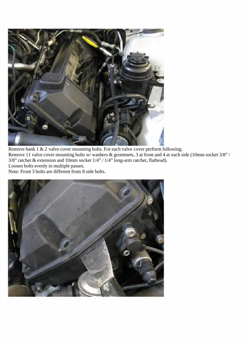
Remove bank 1 & 2 valve cover mounting bolts. For each valve cover perform following.Remove 11 valve cover mounting bolts w/ washers & grommets, 3 at front and 4 at each side (10mm socket 3/8” /3/8” ratchet & extension and 10mm socket 1/4” / 1/4” long-arm ratchet, flathead).Loosen bolts evenly in multiple passes.Note: Front 3 bolts are different from 8 side bolts.
7/29/2019 Removing and Cleaning a Mkiv Throttle Body
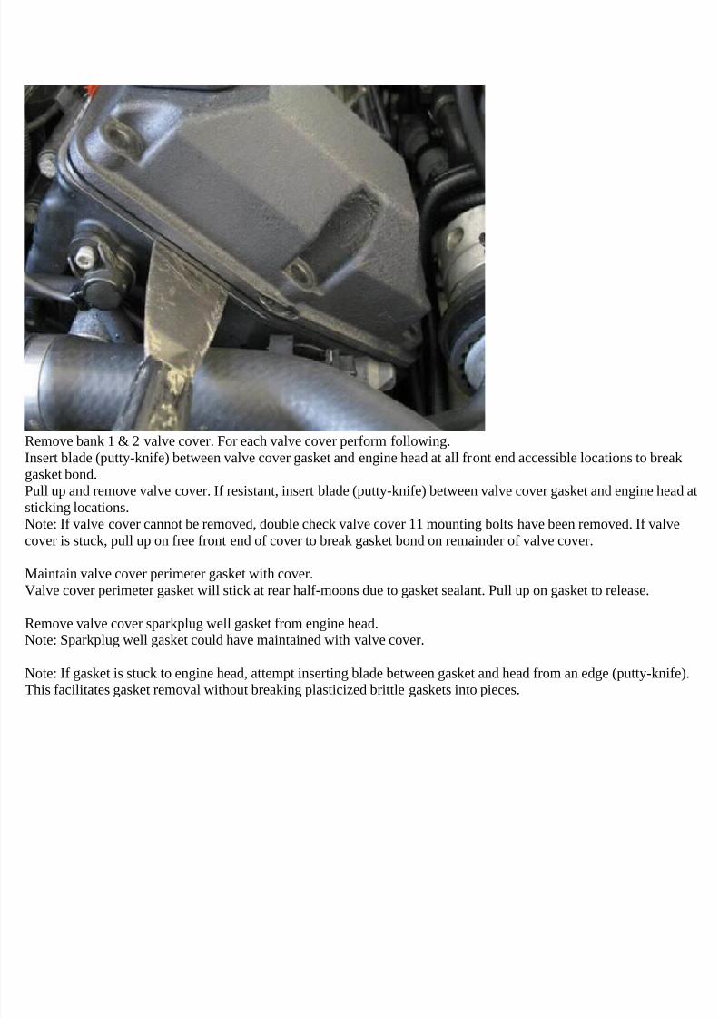
Remove bank 1 & 2 valve cover. For each valve cover perform following.Insert blade (putty-knife) between valve cover gasket and engine head at all front end accessible locations to breakgasket bond.Pull up and remove valve cover. If resistant, insert blade (putty-knife) between valve cover gasket and engine head atsticking locations.Note: If valve cover cannot be removed, double check valve cover 11 mounting bolts have been removed. If valve
cover is stuck, pull up on free front end of cover to break gasket bond on remainder of valve cover.
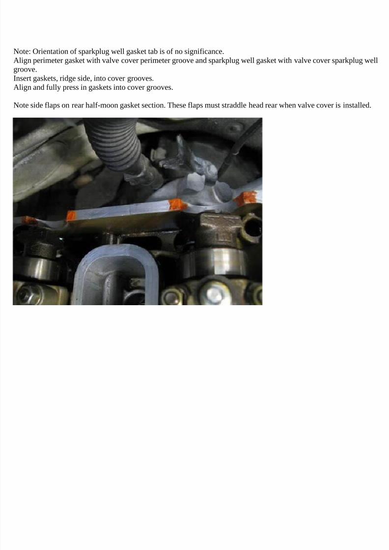
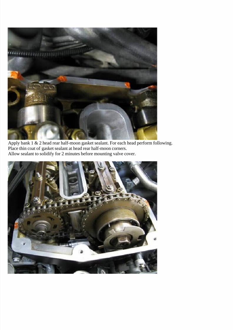
Maintain valve cover perimeter gasket with cover.Valve cover perimeter gasket will stick at rear half-moons due to gasket sealant. Pull up on gasket to release.
Remove valve cover sparkplug well gasket from engine head.Note: Sparkplug well gasket could have maintained with valve cover.
Note: If gasket is stuck to engine head, attempt inserting blade between gasket and head from an edge (putty-knife).This facilitates gasket removal without breaking plasticized brittle gaskets into pieces.
7/29/2019 Removing and Cleaning a Mkiv Throttle Body
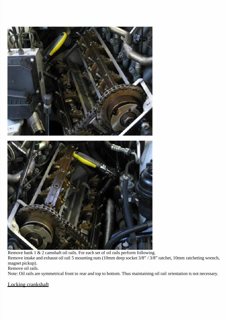
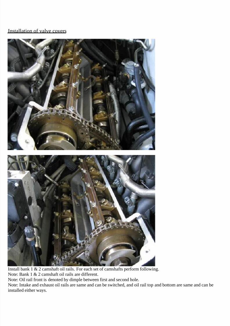
Remove bank 1 & 2 camshaft oil rails. For each set of oil rails perform following.Remove intake and exhaust oil rail 5 mounting nuts (10mm deep socket 3/8” / 3/8” ratchet, 10mm ratcheting wrench,magnet pickup).Remove oil rails.Note: Oil rails are symmetrical front to rear and top to bottom. Thus maintaining oil rail orientation is not necessary.
Locking crankshaft
7/29/2019 Removing and Cleaning a Mkiv Throttle Body
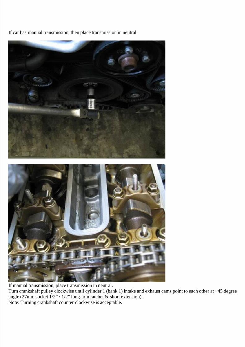
If car has manual transmission, then place transmission in neutral.
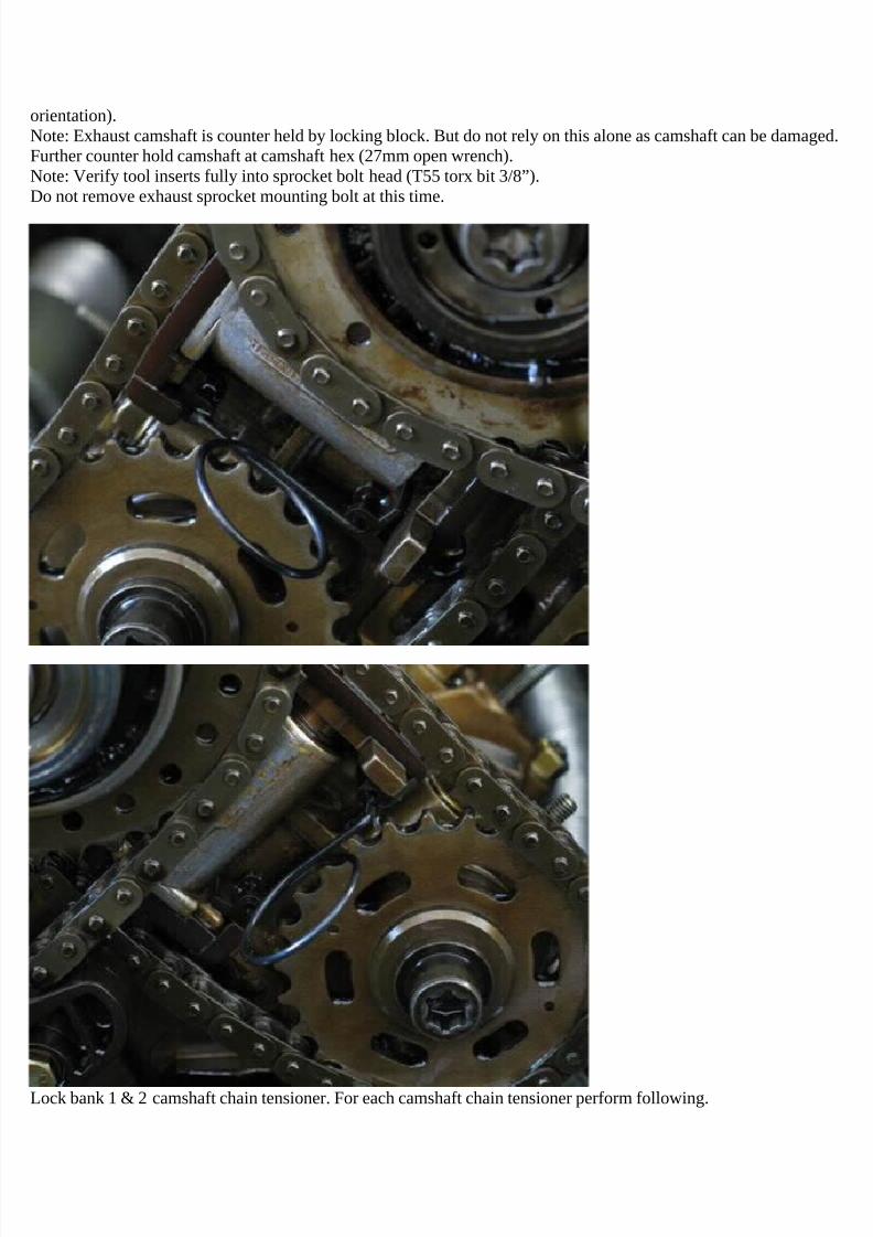
If manual transmission, place transmission in neutral.Turn crankshaft pulley clockwise until cylinder 1 (bank 1) intake and exhaust cams point to each other at ~45 degreeangle (27mm socket 1/2” / 1/2” long-arm ratchet & short extension).
Note: Turning crankshaft counter clockwise is acceptable.
7/29/2019 Removing and Cleaning a Mkiv Throttle Body
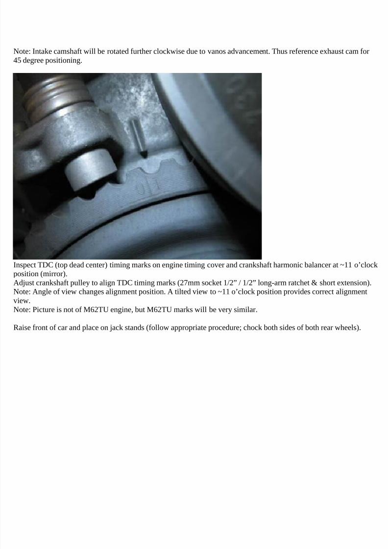
Note: Intake camshaft will be rotated further clockwise due to vanos advancement. Thus reference exhaust cam for45 degree positioning.
Inspect TDC (top dead center) timing marks on engine timing cover and crankshaft harmonic balancer at ~11 o’clockposition (mirror).Adjust crankshaft pulley to align TDC timing marks (27mm socket 1/2” / 1/2” long-arm ratchet & short extension).Note: Angle of view changes alignment position. A tilted view to ~11 o’clock position provides correct alignmentview.Note: Picture is not of M62TU engine, but M62TU marks will be very similar.
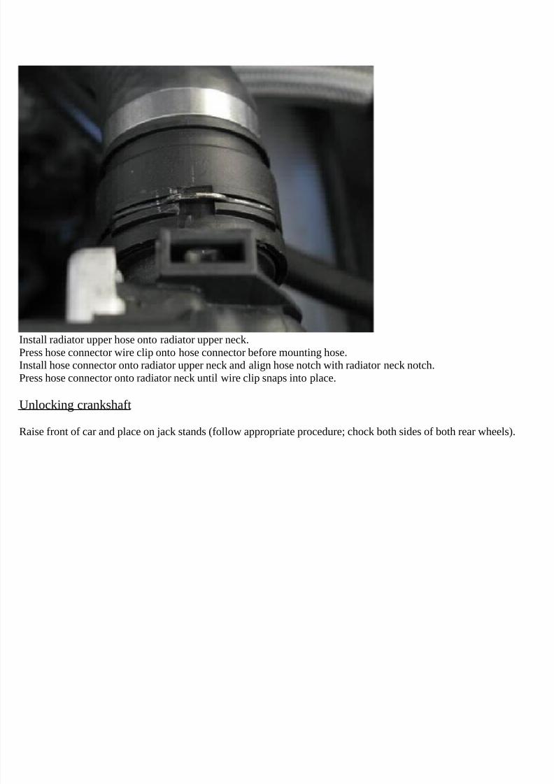
Raise front of car and place on jack stands (follow appropriate procedure; chock both sides of both rear wheels).
7/29/2019 Removing and Cleaning a Mkiv Throttle Body
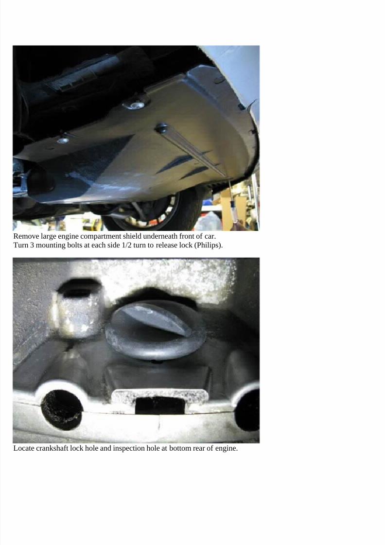
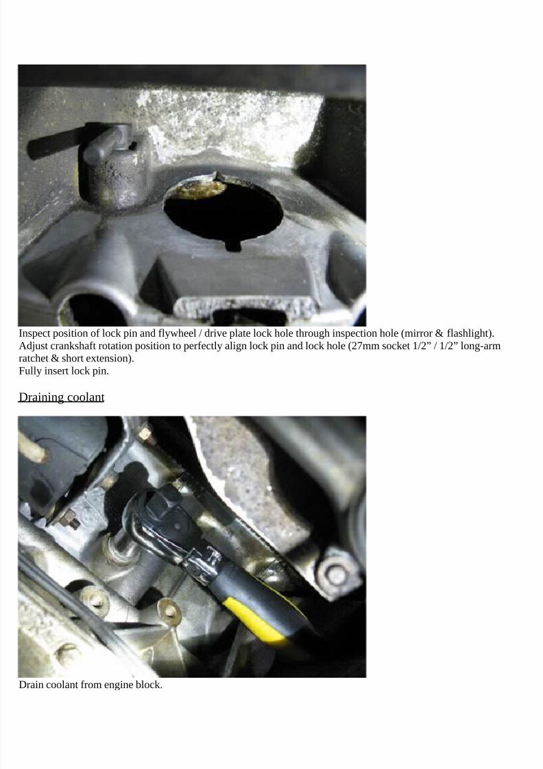
Remove engine left side (front orientation) coolant drain bolt (13mm socket 3/8” / 3/8” ratchet).Note: Drain bolt located on engine block between cyl 2 & 3.Catch draining coolant in receptacle (coolant receptacle).
Remove and discard bolt crush washer.
Note: If washer not on bolt it is likely at hole or fallen in coolant receptacle.
Note: It is not necessary to drain coolant from engine right side. This does not affect repair and there is very littlecoolant to drain and thus is of no significance.
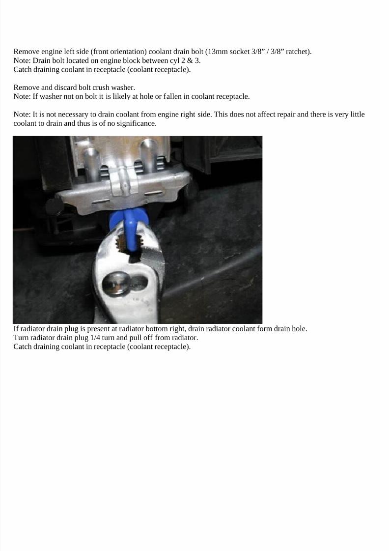
If radiator drain plug is present at radiator bottom right, drain radiator coolant form drain hole.Turn radiator drain plug 1/4 turn and pull off from radiator.Catch draining coolant in receptacle (coolant receptacle).
7/29/2019 Removing and Cleaning a Mkiv Throttle Body
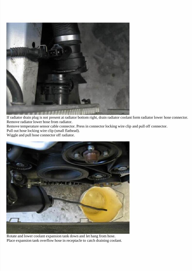
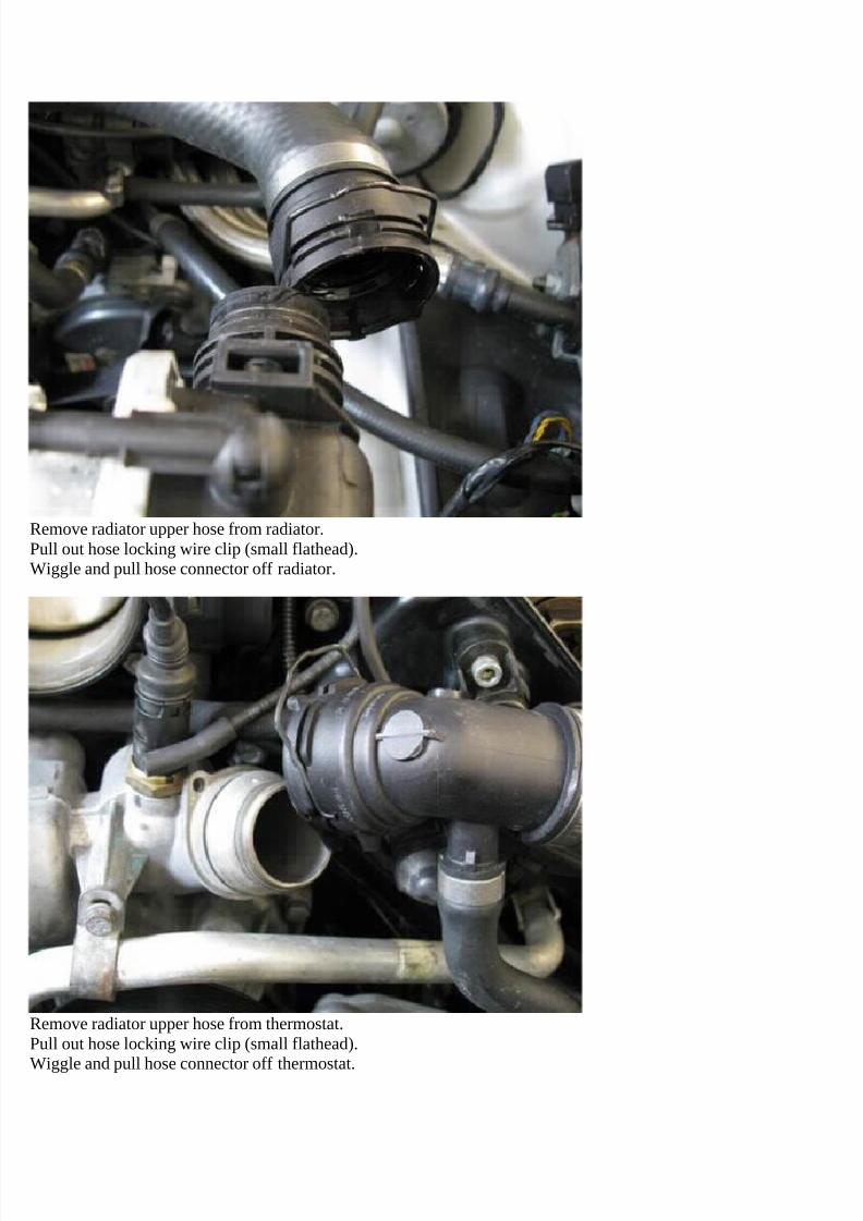
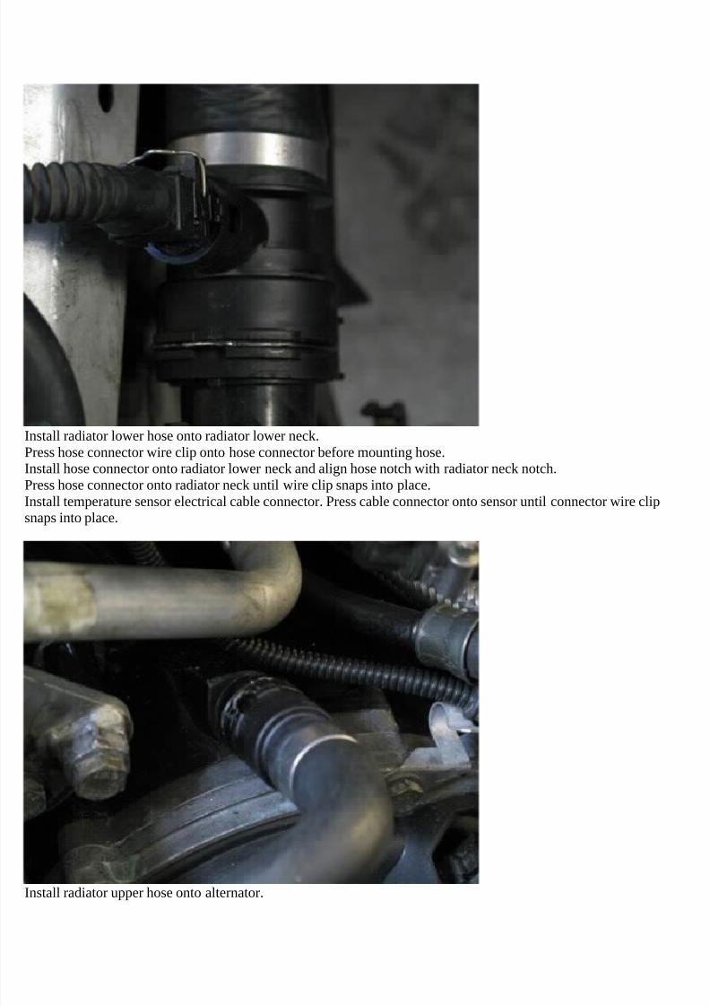
If radiator drain plug is not present at radiator bottom right, drain radiator coolant form radiator lower hose connector.Remove radiator lower hose from radiator.Remove temperature sensor cable connector. Press in connector locking wire clip and pull off connector.Pull out hose locking wire clip (small flathead).Wiggle and pull hose connector off radiator.
Rotate and lower coolant expansion tank down and let hang from hose.Place expansion tank overflow hose in receptacle to catch draining coolant.
7/29/2019 Removing and Cleaning a Mkiv Throttle Body
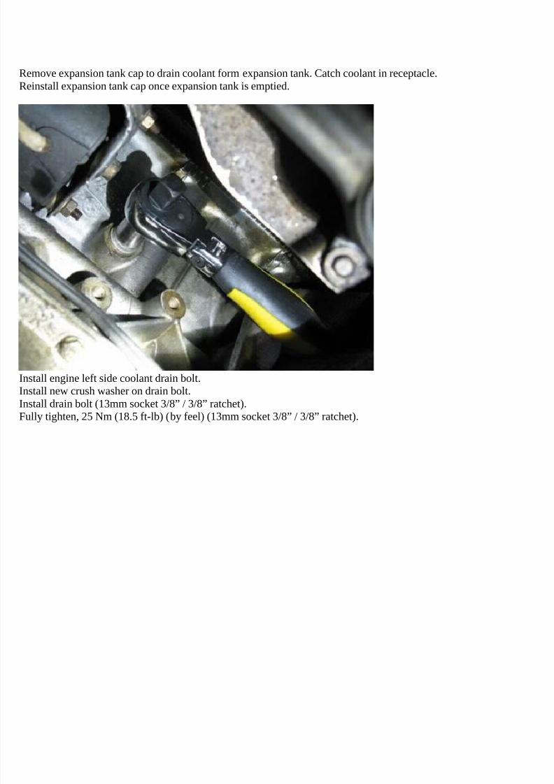
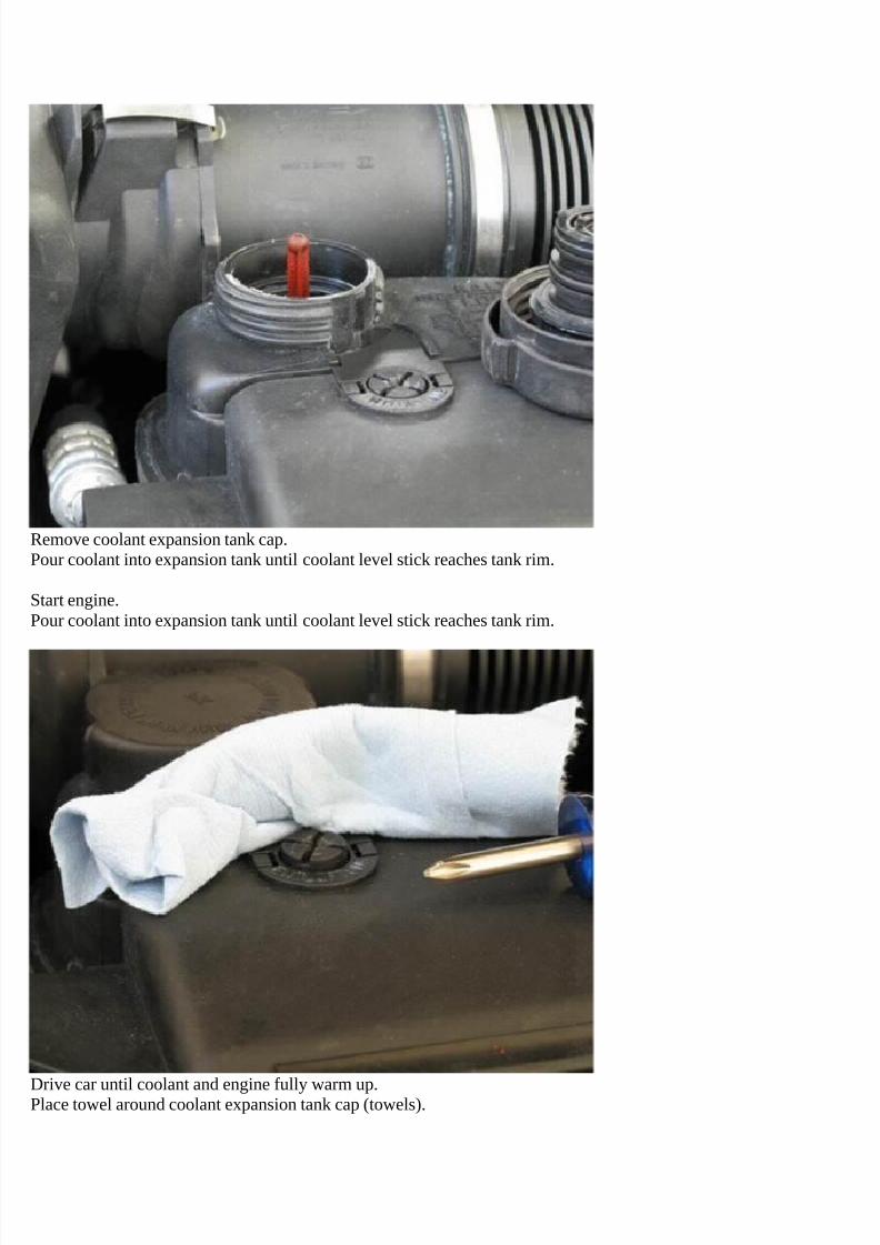
Remove expansion tank cap to drain coolant form expansion tank. Catch coolant in receptacle.Reinstall expansion tank cap once expansion tank is emptied.
Install engine left side coolant drain bolt.Install new crush washer on drain bolt.Install drain bolt (13mm socket 3/8” / 3/8” ratchet).Fully tighten, 25 Nm (18.5 ft-lb) (by feel) (13mm socket 3/8” / 3/8” ratchet).
7/29/2019 Removing and Cleaning a Mkiv Throttle Body
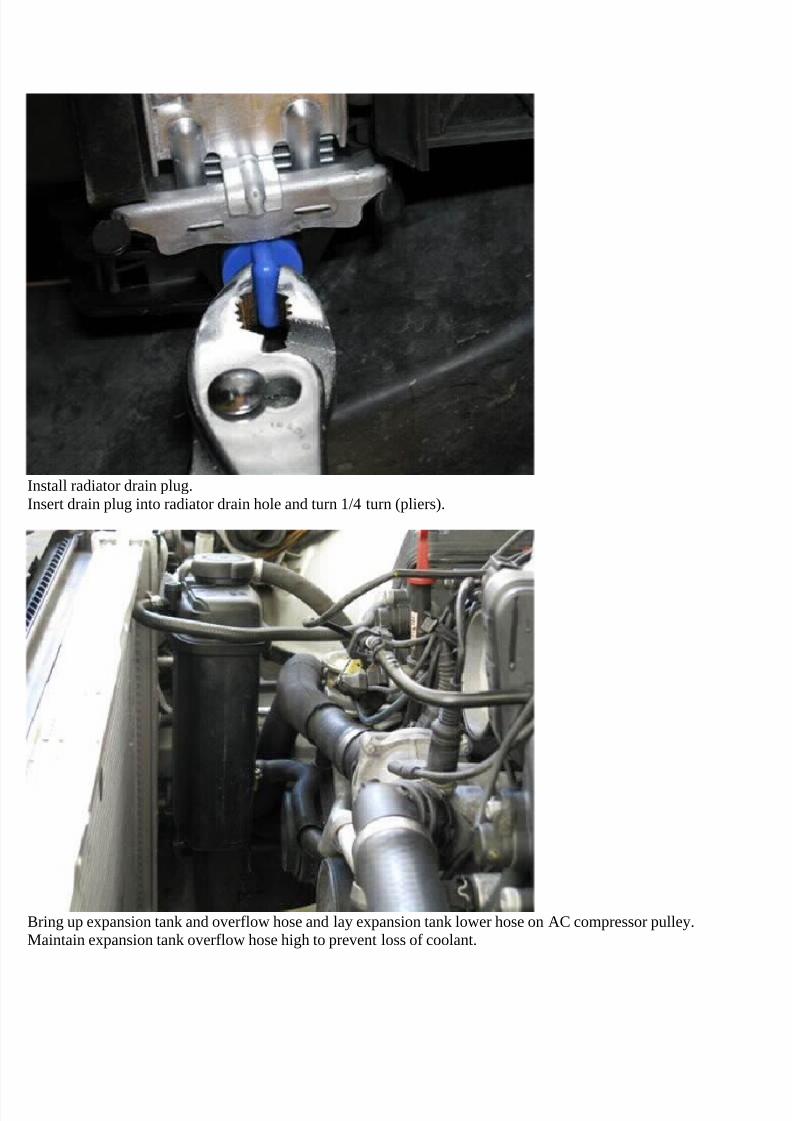
Install radiator drain plug.Insert drain plug into radiator drain hole and turn 1/4 turn (pliers).
Bring up expansion tank and overflow hose and lay expansion tank lower hose on AC compressor pulley.Maintain expansion tank overflow hose high to prevent loss of coolant.
7/29/2019 Removing and Cleaning a Mkiv Throttle Body
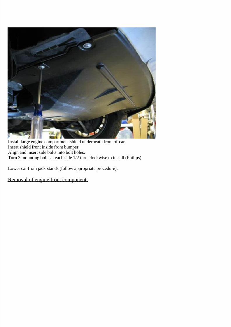
Install large engine compartment shield underneath front of car.Insert shield front inside front bumper.Align and insert side bolts into bolt holes.Turn 3 mounting bolts at each side 1/2 turn clockwise to install (Philips).
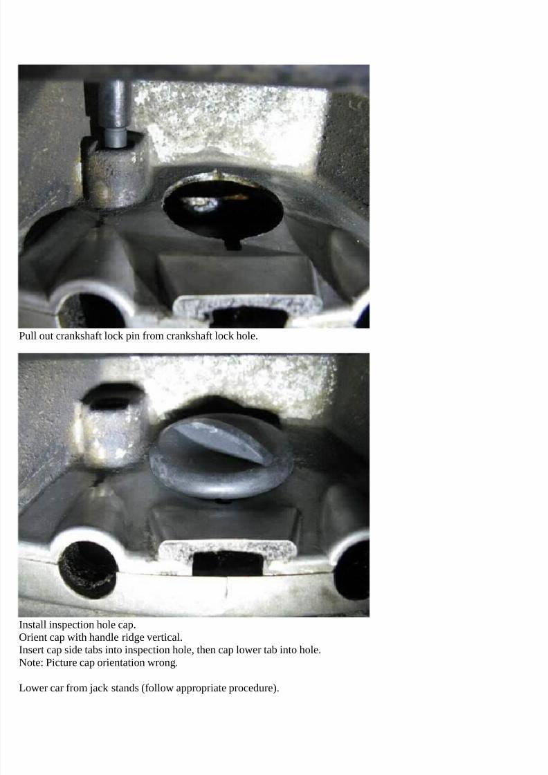
Lower car from jack stands (follow appropriate procedure).
Removal of engine front components
7/29/2019 Removing and Cleaning a Mkiv Throttle Body
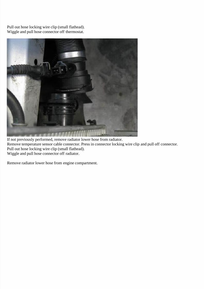
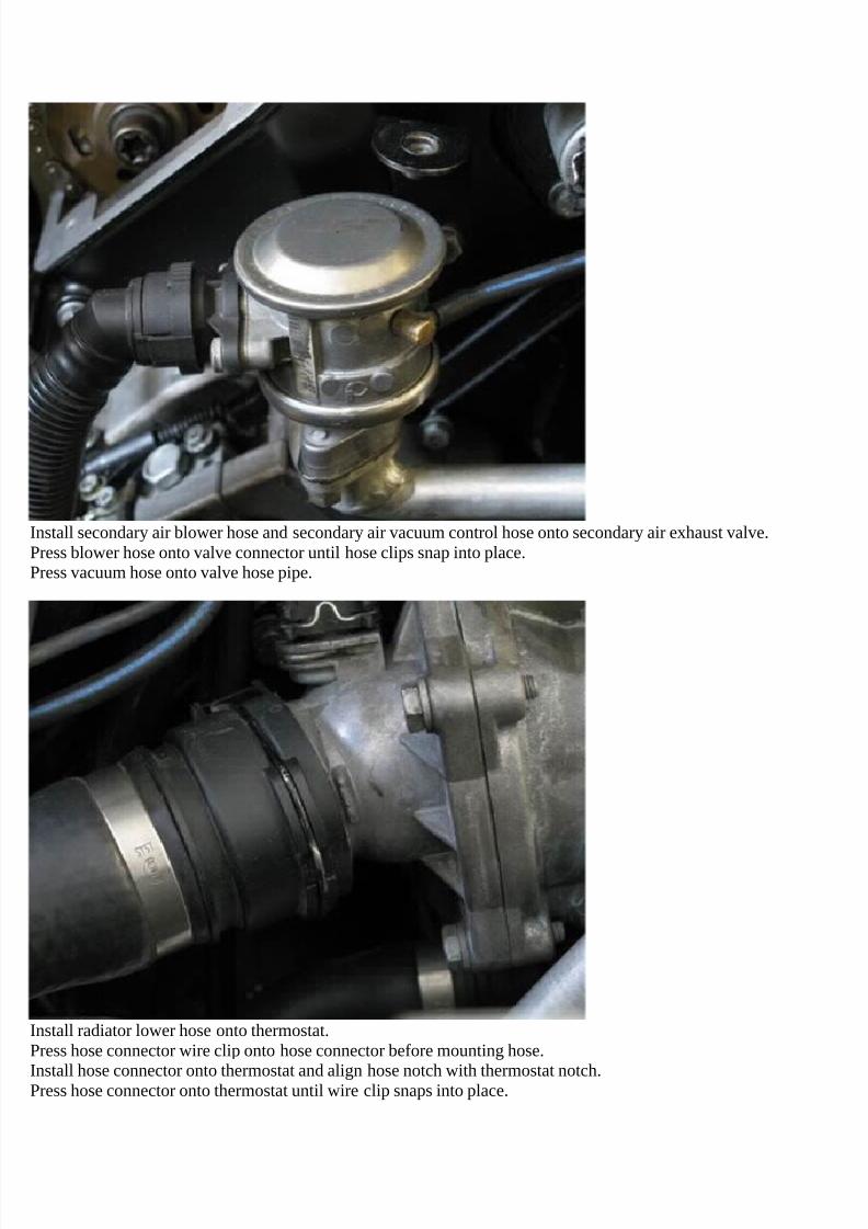
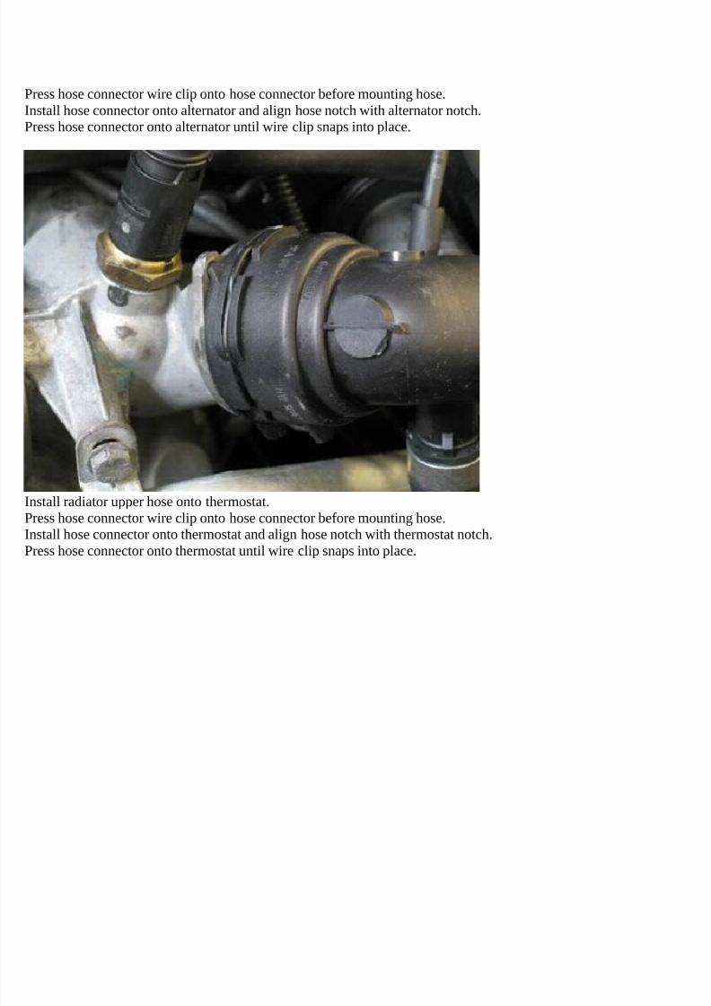
Pull out hose locking wire clip (small flathead).Wiggle and pull hose connector off thermostat.
If not previously performed, remove radiator lower hose from radiator.Remove temperature sensor cable connector. Press in connector locking wire clip and pull off connector.Pull out hose locking wire clip (small flathead).Wiggle and pull hose connector off radiator.
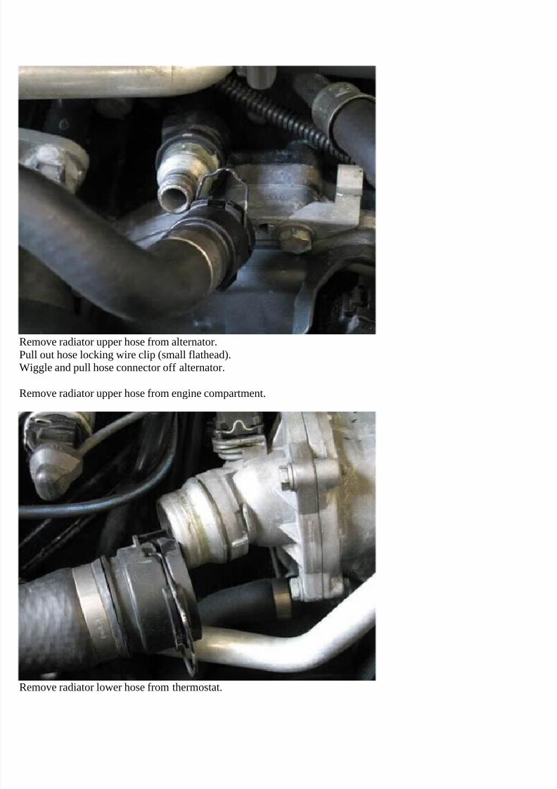
Remove radiator lower hose from engine compartment.
7/29/2019 Removing and Cleaning a Mkiv Throttle Body
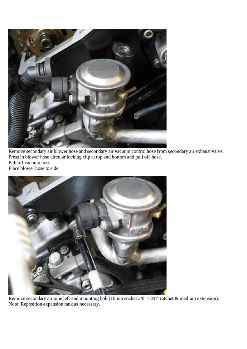
Remove secondary air blower hose and secondary air vacuum control hose from secondary air exhaust valve.Press in blower hose circular locking clip at top and bottom and pull off hose.Pull off vacuum hose.Place blower hose to side.
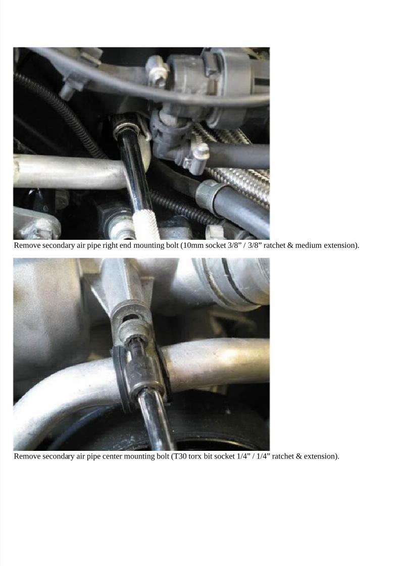
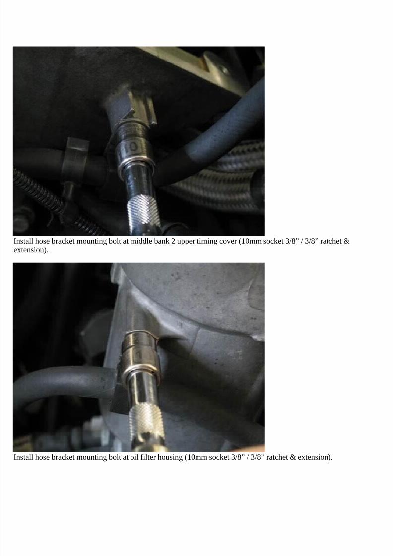
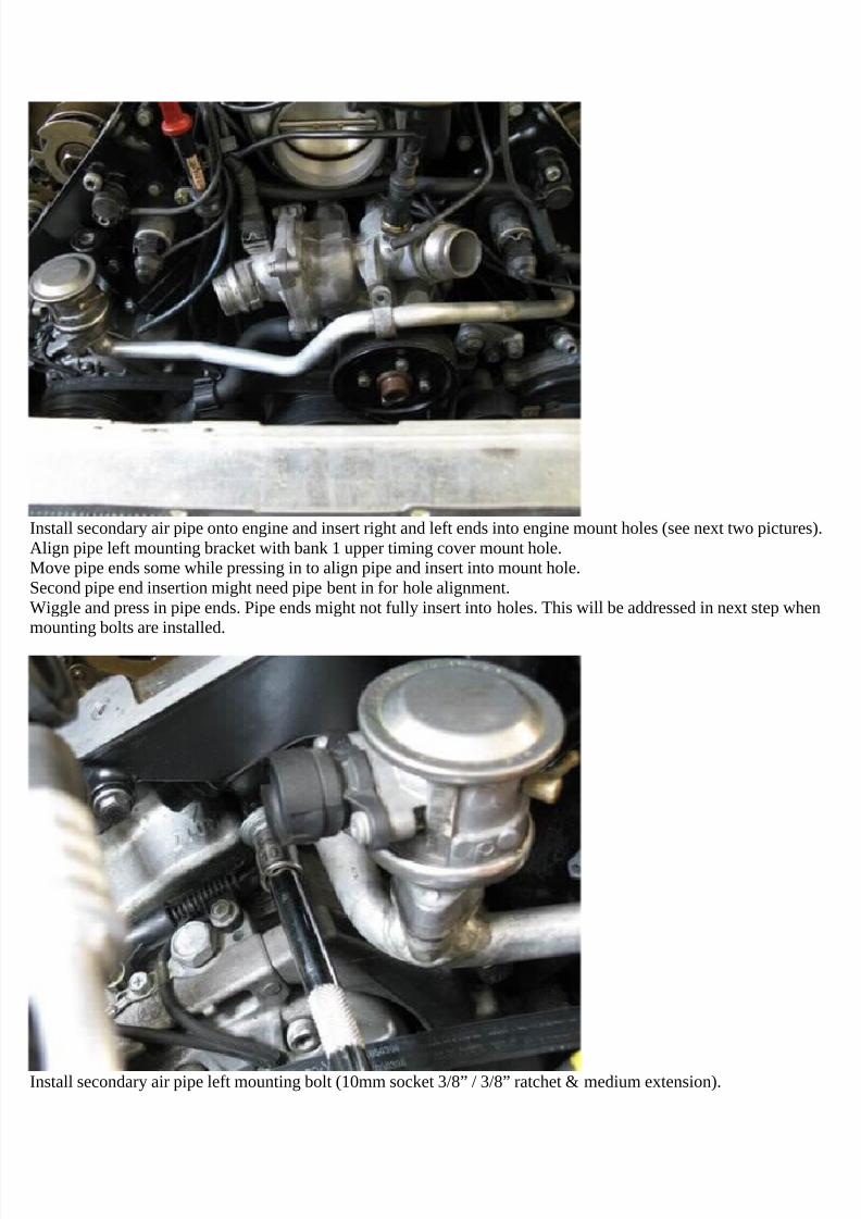
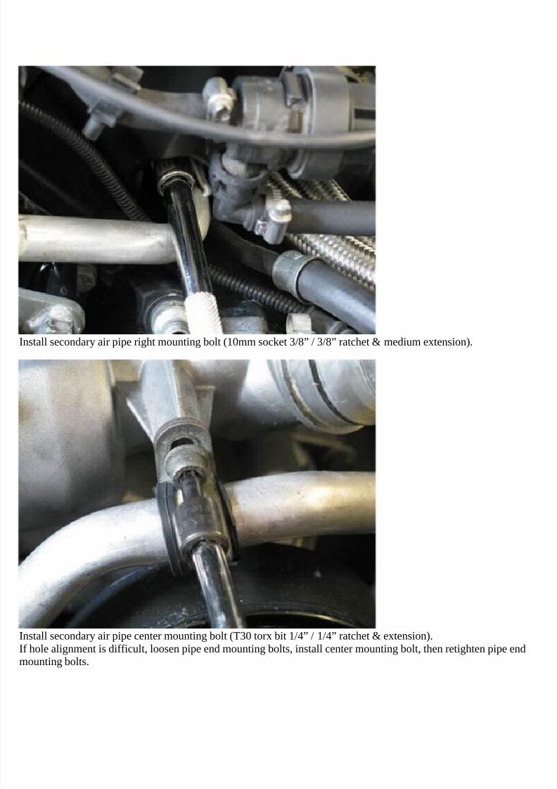
Remove secondary air pipe left end mounting bolt (10mm socket 3/8” / 3/8” ratchet & medium extension).
Note: Reposition expansion tank as necessary.
7/29/2019 Removing and Cleaning a Mkiv Throttle Body
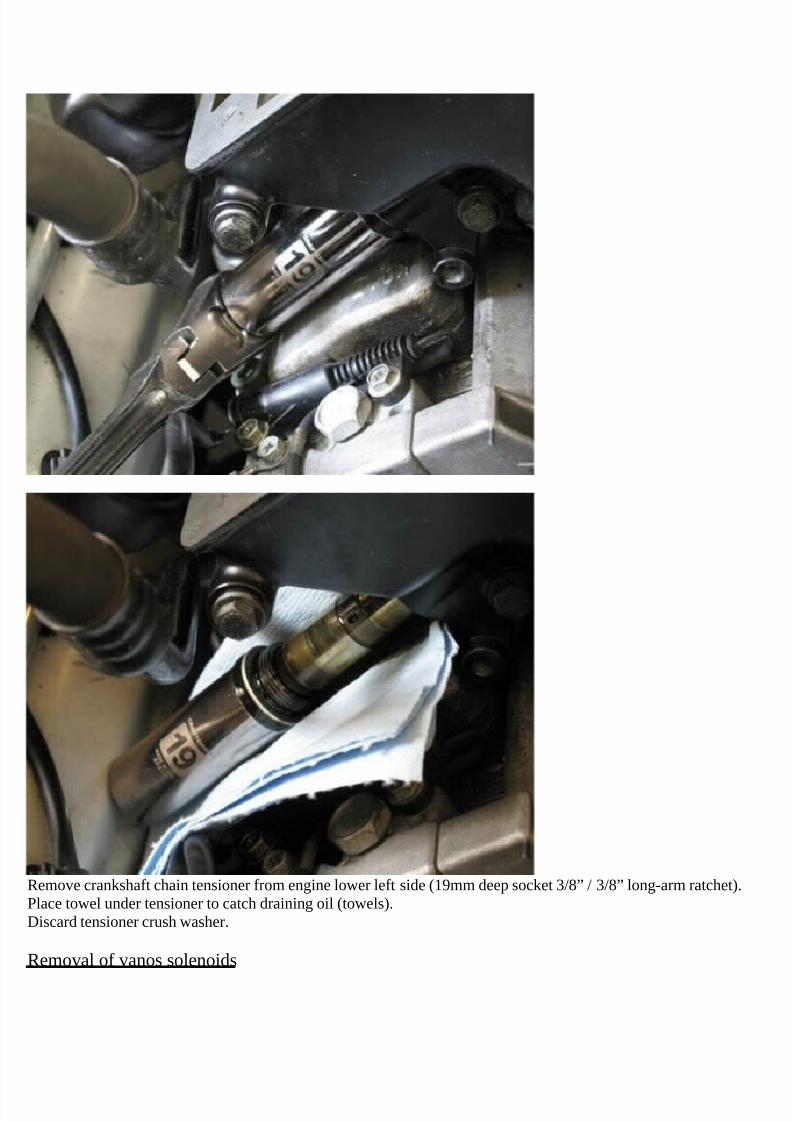
Remove crankshaft chain tensioner from engine lower left side (19mm deep socket 3/8” / 3/8” long-arm ratchet).Place towel under tensioner to catch draining oil (towels).Discard tensioner crush washer.
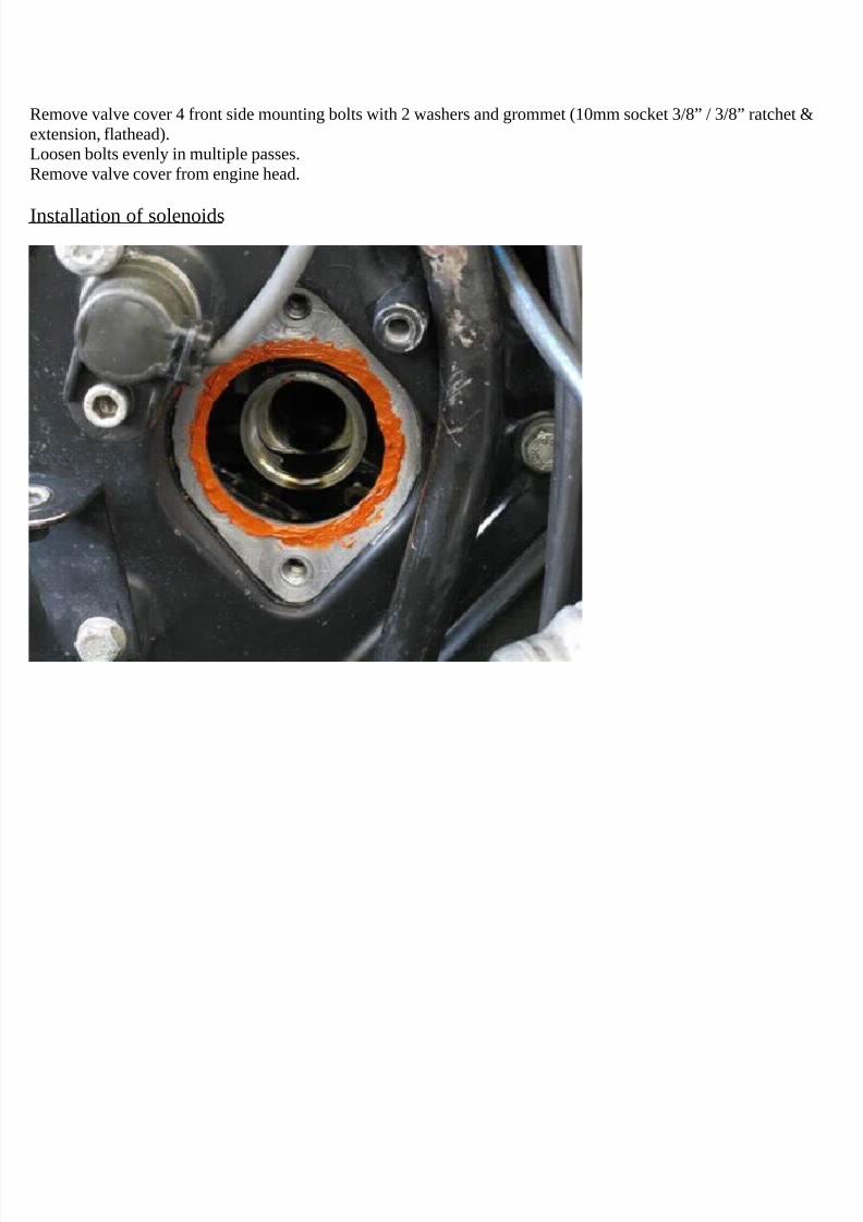
Removal of vanos solenoids
7/29/2019 Removing and Cleaning a Mkiv Throttle Body
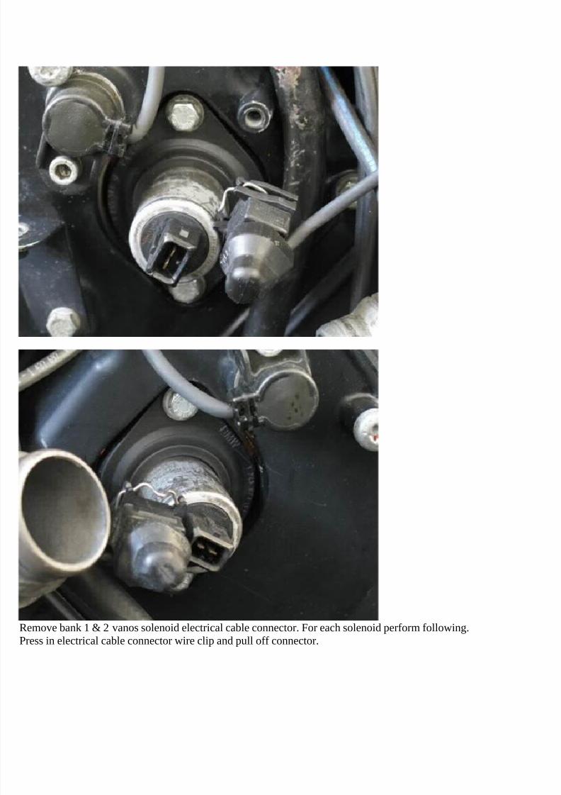
Remove bank 1 & 2 vanos solenoid electrical cable connector. For each solenoid perform following.Press in electrical cable connector wire clip and pull off connector.
7/29/2019 Removing and Cleaning a Mkiv Throttle Body
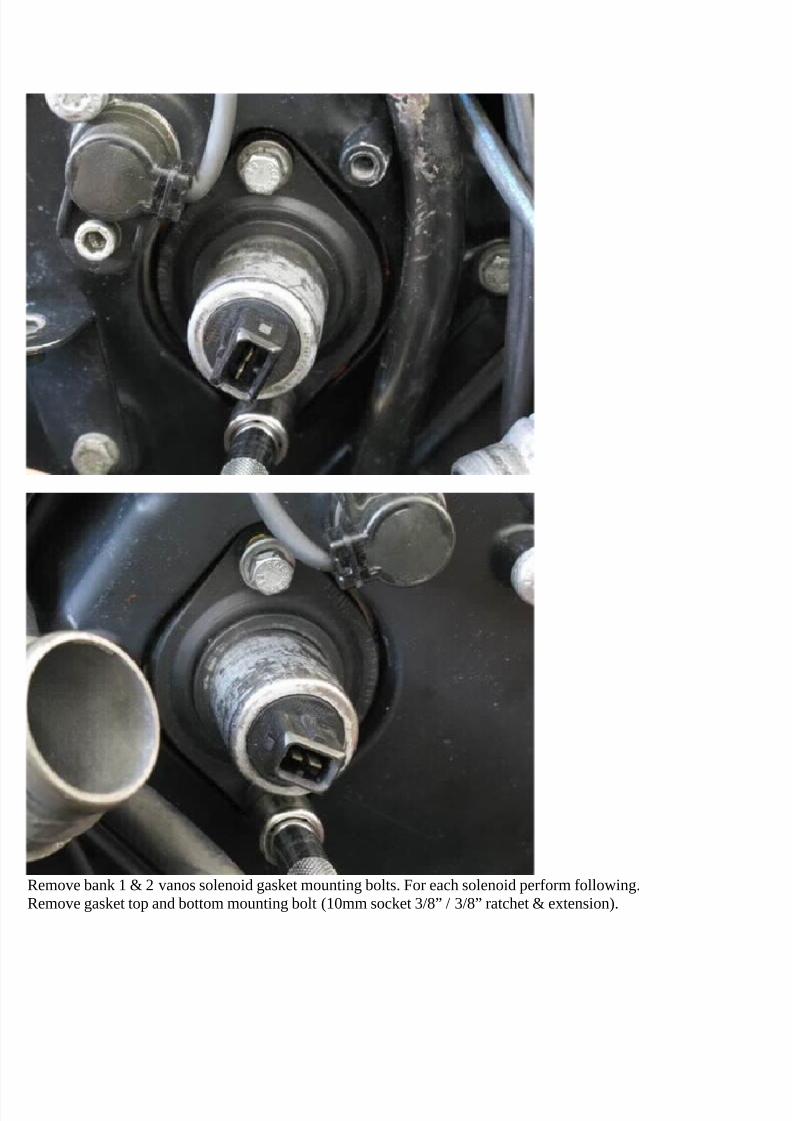
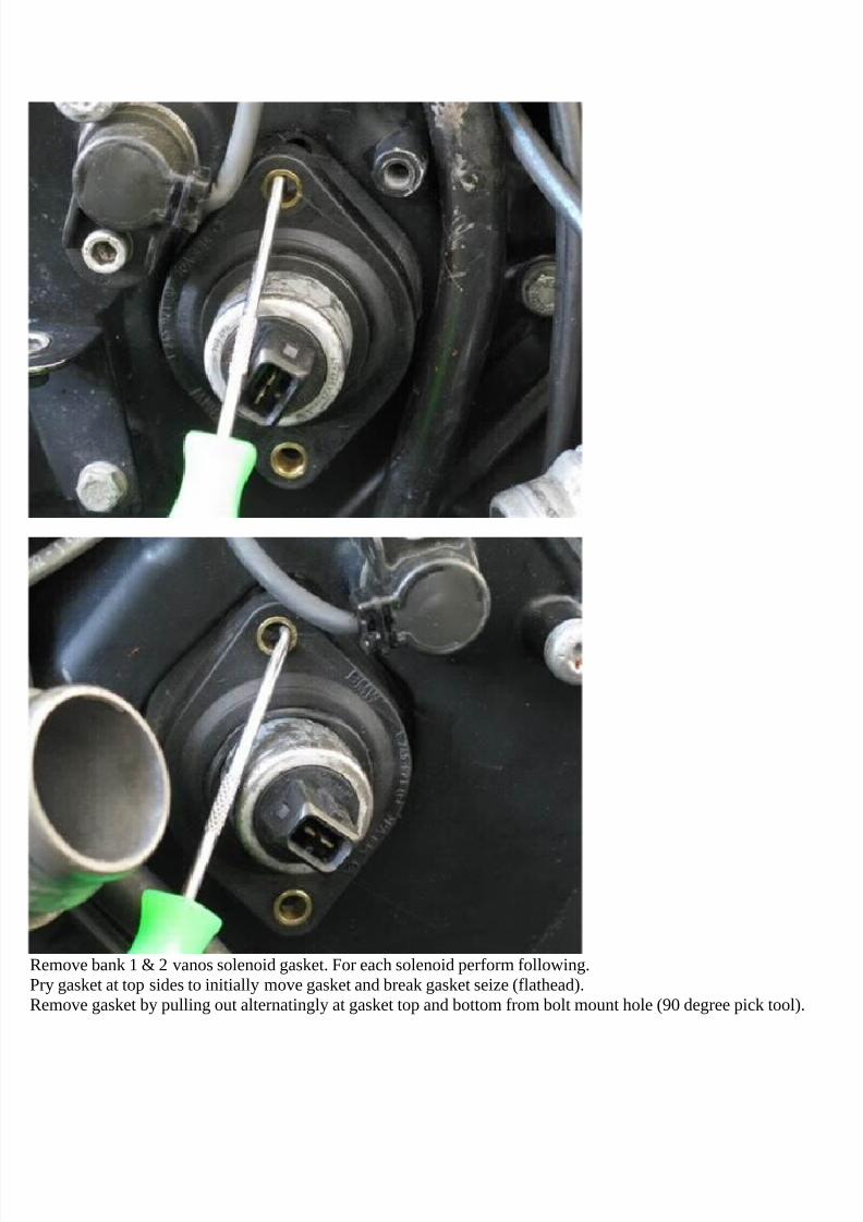
Remove bank 1 & 2 vanos solenoid gasket. For each solenoid perform following.Pry gasket at top sides to initially move gasket and break gasket seize (flathead).Remove gasket by pulling out alternatingly at gasket top and bottom from bolt mount hole (90 degree pick tool).
7/29/2019 Removing and Cleaning a Mkiv Throttle Body
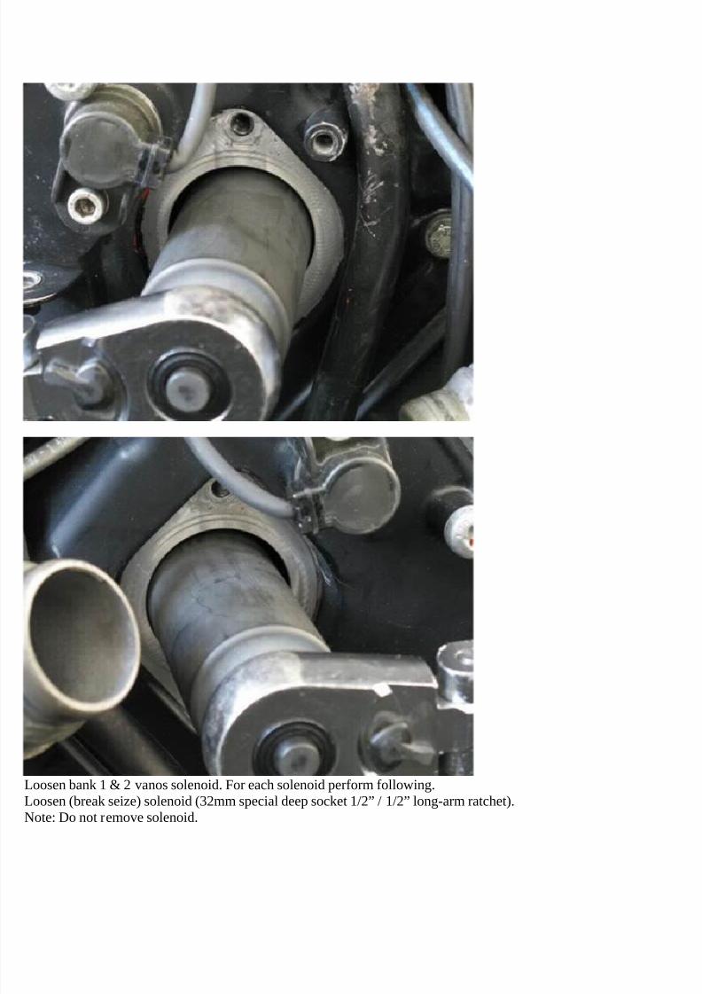
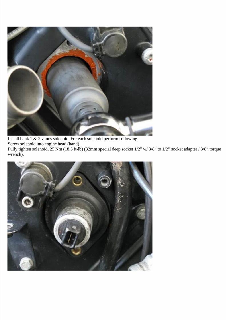
Loosen bank 1 & 2 vanos solenoid. For each solenoid perform following.Loosen (break seize) solenoid (32mm special deep socket 1/2” / 1/2” long-arm ratchet).Note: Do not remove solenoid.
7/29/2019 Removing and Cleaning a Mkiv Throttle Body
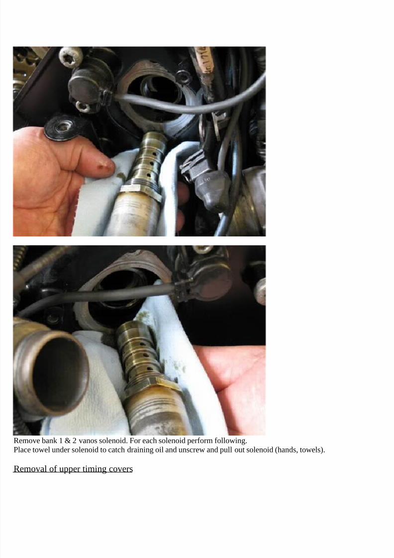
Remove bank 1 & 2 vanos solenoid. For each solenoid perform following.Place towel under solenoid to catch draining oil and unscrew and pull out solenoid (hands, towels).
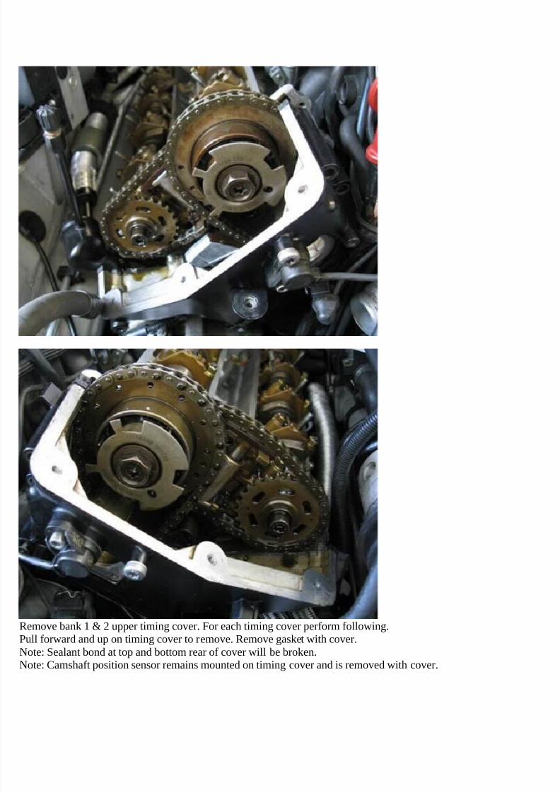
Removal of upper timing covers
7/29/2019 Removing and Cleaning a Mkiv Throttle Body
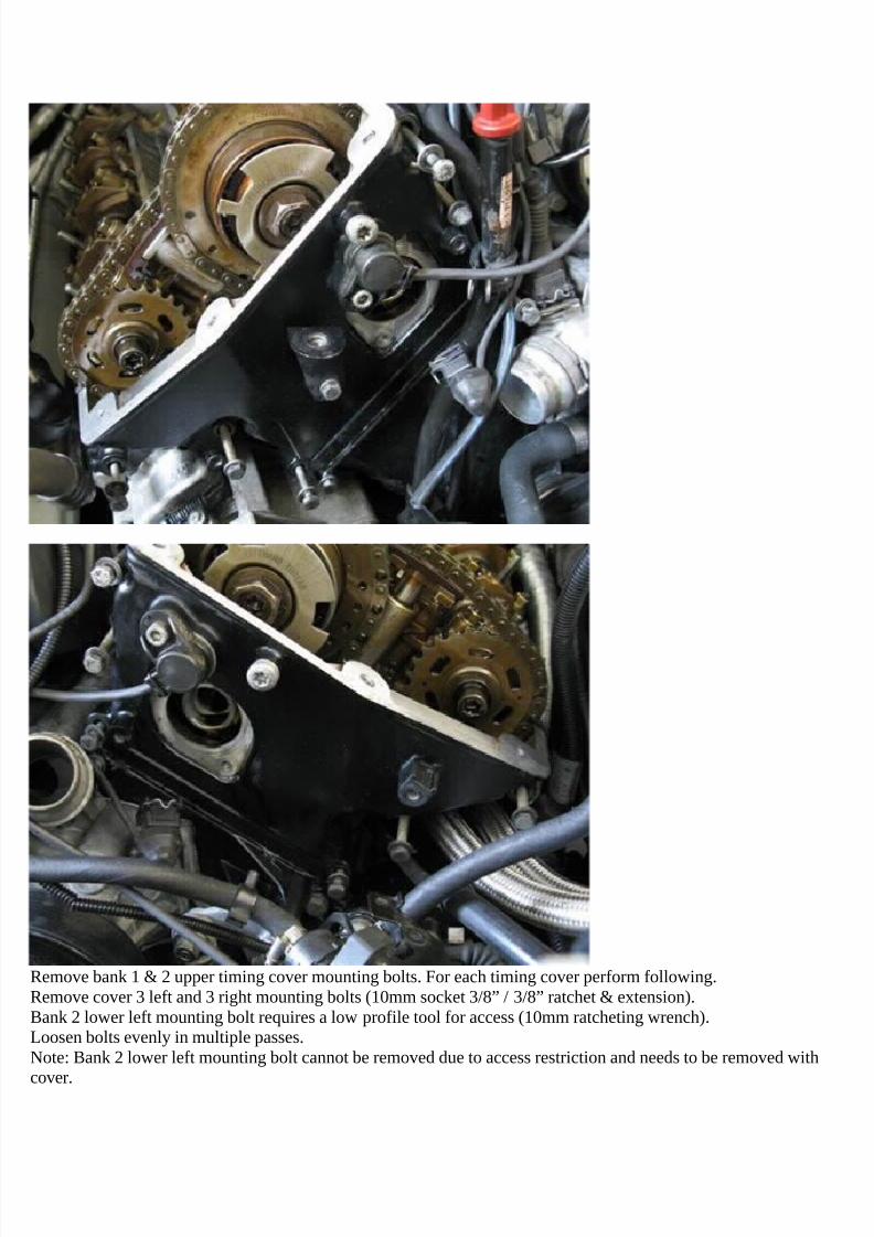
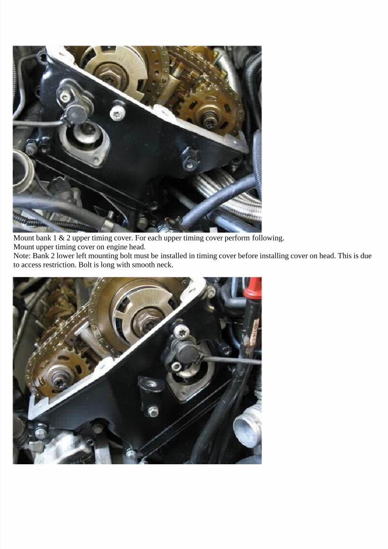
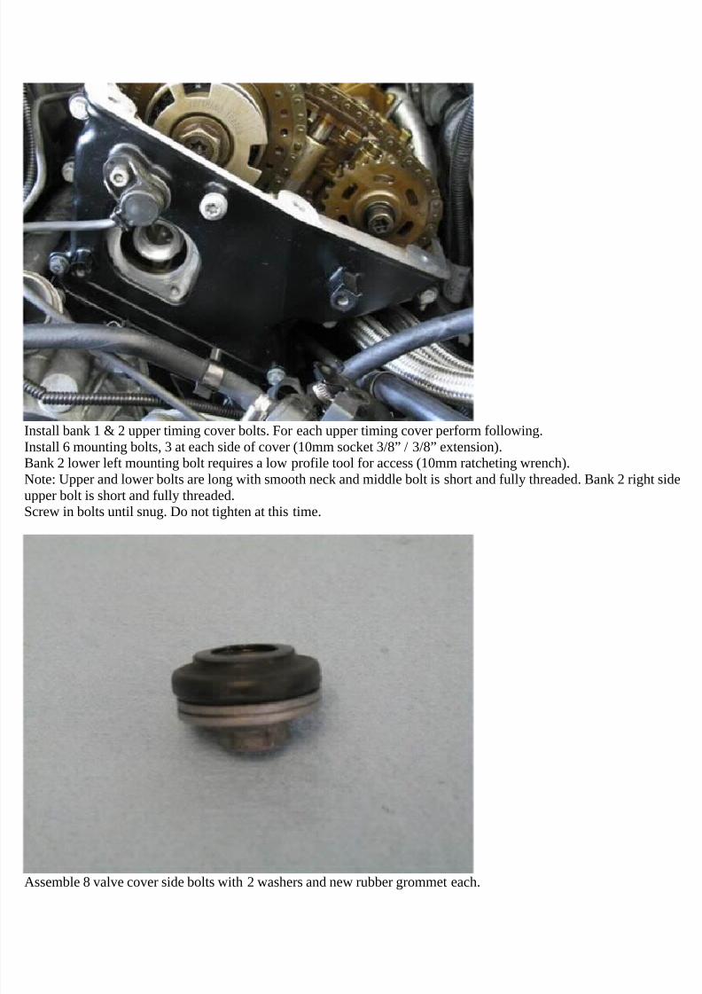
Remove bank 1 & 2 upper timing cover mounting bolts. For each timing cover perform following.Remove cover 3 left and 3 right mounting bolts (10mm socket 3/8” / 3/8” ratchet & extension).Bank 2 lower left mounting bolt requires a low profile tool for access (10mm ratcheting wrench).Loosen bolts evenly in multiple passes.Note: Bank 2 lower left mounting bolt cannot be removed due to access restriction and needs to be removed with
cover.
7/29/2019 Removing and Cleaning a Mkiv Throttle Body
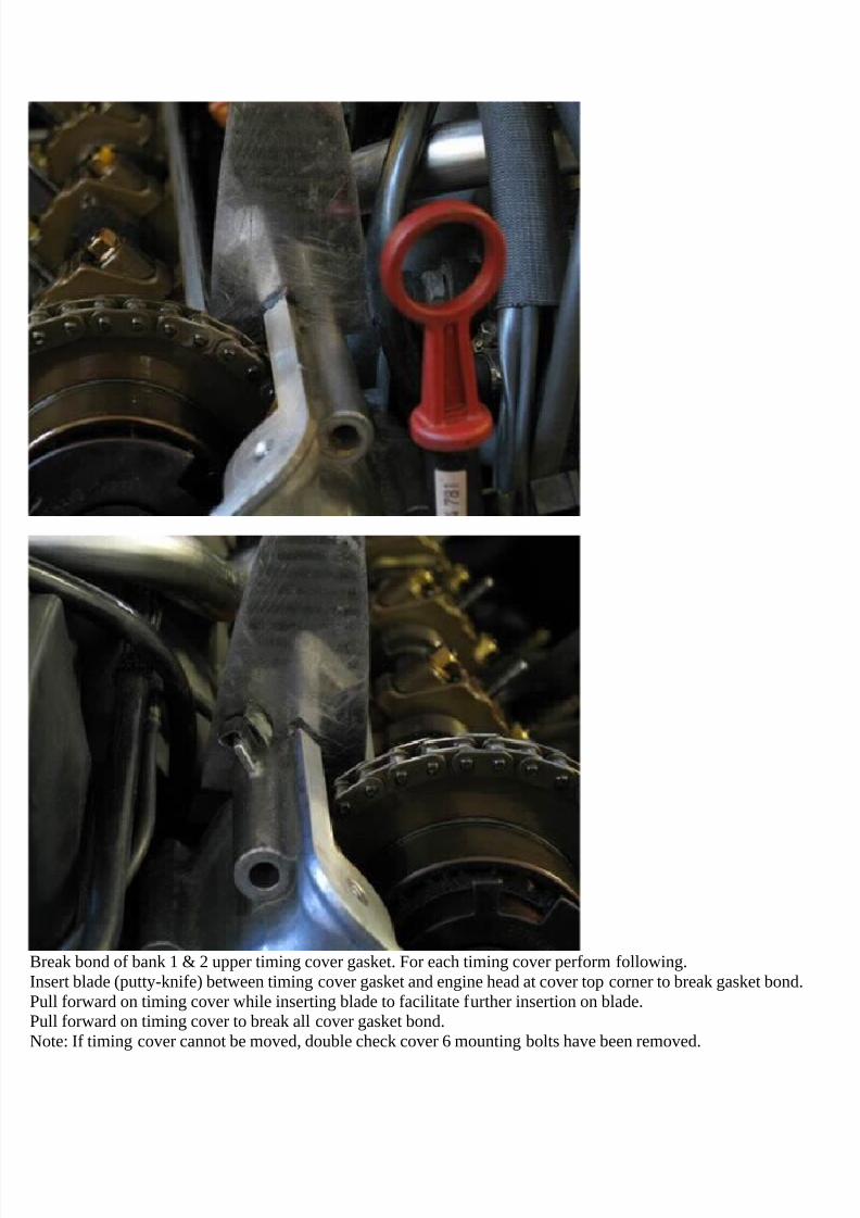
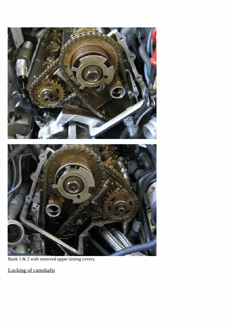
Break bond of bank 1 & 2 upper timing cover gasket. For each timing cover perform following.Insert blade (putty-knife) between timing cover gasket and engine head at cover top corner to break gasket bond.Pull forward on timing cover while inserting blade to facilitate further insertion on blade.Pull forward on timing cover to break all cover gasket bond.Note: If timing cover cannot be moved, double check cover 6 mounting bolts have been removed.
7/29/2019 Removing and Cleaning a Mkiv Throttle Body
Remove bank 1 & 2 upper timing cover. For each timing cover perform following.Pull forward and up on timing cover to remove. Remove gasket with cover.Note: Sealant bond at top and bottom rear of cover will be broken.Note: Camshaft position sensor remains mounted on timing cover and is removed with cover.
7/29/2019 Removing and Cleaning a Mkiv Throttle Body
Install bank 1 & 2 camshaft locking blocks. For each camshaft set perform following.Note: If locking blocks are marked in German, E is intake and A is exhaust.Place locking block set on intake and exhaust camshaft rear square ends.Adjust each camshaft position as needed to align for locking block insertion (27mm open wrench).Note: Each camshaft incorporates a hex to facilitate camshaft rotation.
Loosen and retighten locking blocks matting bolt as needed to facilitate block mounting (6mm hex bit socket 3/8” /3/8” ratchet).
7/29/2019 Removing and Cleaning a Mkiv Throttle Body
Note: Bank 1 intake camshaft will need to be rotated counter clockwise opposing a valve spring to properly positionfor locking block. This is due to valve spring load and vanos timing advance.
Rock each camshaft slightly back and forth while pressing down and forward on locking block to fully seat and alignblock on head surface.
Verify camshaft rear squares inserted into locking blocks rear narrow slot.Note: Camshafts ends extend to rear of camshaft rear squares. Thus camshaft rear squares will not fully seat to rear ofblocks’ rear slot.
Removal of vanos units
During following component removal, maintain component to engine head association. This is not necessary but isgood practice.
7/29/2019 Removing and Cleaning a Mkiv Throttle Body
Remove bank 1 & 2 intake camshaft timing wheel. For each timing wheel perform following.Counter hold intake camshaft and loosen timing wheel mounting nut; left hand thread (24mm socket 1/2" / 1/2"breaker bar, 27mm open wrench).Note: Nut is left hand thread, thus unscrew by turning breaker bar from left to right (clockwise) (car frontorientation).Note: Intake camshaft is counter held by locking block. But do not rely on this alone as camshaft can be damaged.
Further counter hold camshaft at camshaft hex (27mm open wrench).Remove timing wheel and mounting nut.
7/29/2019 Removing and Cleaning a Mkiv Throttle Body
Loosen bank 1 & 2 vanos mounting bolt. For each vanos perform following.Counter hold intake camshaft and loosen vanos mounting bolt; left hand thread (T55 torx bit socket 3/8" / 3/8"breaker bar, 27mm open wrench).Note: Bolt is left hand thread, thus unscrew by turning breaker bar from left to right (clockwise) (car frontorientation).
Note: Intake camshaft is counter held by locking block. But do not rely on this alone as camshaft can be damaged.Further counter hold camshaft at camshaft hex (27mm open wrench).
7/29/2019 Removing and Cleaning a Mkiv Throttle Body
Note: Verify tool inserts fully into vanos bolt head (T55 torx bit 3/8”).Do not remove vanos mounting bolt at this time.
Loosen bank 1 & 2 exhaust sprocket mounting bolt. For each exhaust sprocket perform following.Counter hold exhaust camshaft and loosen exhaust sprocket mounting bolt; left hand thread (T55 torx bit socket 3/8" /
3/8" breaker bar, 27mm open wrench).Note: Bolt is left hand thread, thus unscrew by turning breaker bar from left to right (clockwise) (car front
7/29/2019 Removing and Cleaning a Mkiv Throttle Body
orientation).Note: Exhaust camshaft is counter held by locking block. But do not rely on this alone as camshaft can be damaged.Further counter hold camshaft at camshaft hex (27mm open wrench).Note: Verify tool inserts fully into sprocket bolt head (T55 torx bit 3/8”).Do not remove exhaust sprocket mounting bolt at this time.
Lock bank 1 & 2 camshaft chain tensioner. For each camshaft chain tensioner perform following.
7/29/2019 Removing and Cleaning a Mkiv Throttle Body
Compress chain tensioner and fully insert locking clip into locking holes.Note: Bank 1 chain tensioner is compressed from below tensioner and bank 2 chain tensioner is compressed fromabove tensioner.Note: If locking clip not fully inserting, remove clip and press in locking clip pins to make parallel, then reattemptinsertion.
Remove bank 1 & 2 vanos and exhaust sprocket mounting bolts. For each vanos and exhaust sprocket perform
7/29/2019 Removing and Cleaning a Mkiv Throttle Body
Remove bank 1 & 2 exhaust sprocket and camshaft chain. For each exhaust sprocket and camshaft chain performfollowing.Pull vanos and exhaust sprocket forward and off camshafts.Move exhaust sprocket closer to vanos to loosen camshaft chain and remove chain from vanos rear sprocket.Reinstall vanos onto intake camshaft.
Remove exhaust sprocket and camshaft timing chain.
7/29/2019 Removing and Cleaning a Mkiv Throttle Body
Remove bank 1 & 2 vanos. For each vanos perform following.Pull vanos forward and off intake camshaft.Remove crankshaft chain from vanos sprocket. Remove vanos.Maneuver crankshaft chain past distribution piece and lay down to side of engine.
Caution: Do not remove vanos center shaft from vanos body. Shaft is balanced to vanos body and must be markedbefore removal.
7/29/2019 Removing and Cleaning a Mkiv Throttle Body
Cover up bank 1 & 2 crankshaft chain access slot. For each chain slot perform following.Lay towel over chain slot (towels).Note: Towel will prevent components from dropping in chain slot during following repair steps.
Removal of vanos components
7/29/2019 Removing and Cleaning a Mkiv Throttle Body
Remove bank 1 & 2 vanos oil distribution piece mounting bolts. For each vanos oil distribution piece performfollowing.Loosen then remove distribution piece 5 mounting bolts (E-10 torx socket 3/8” / 3/8” ratchet & extension).Note: Lower mounting bolt, just below solenoid hole, is longer and has washer.
7/29/2019 Removing and Cleaning a Mkiv Throttle Body
Remove bank 1 & 2 vanos oil distribution piece. For each vanos oil distribution piece perform following.Pull oil distribution piece from engine head.If distribution piece resistant, pry distribution piece off head while hitting distribution piece cylinder (wide flathead,hard hammer).Note: Distribution piece can be stuck on camshaft due to camshaft seal ring scoring on distribution piece cylinder.
This can be seen once distribution piece is removed.
7/29/2019 Removing and Cleaning a Mkiv Throttle Body
Remove bank 1 & 2 vanos oil distribution piece gasket. For each vanos oil distribution piece gasket performfollowing.Pull off and remove oil distribution piece gasket.Discard distribution piece gasket.
7/29/2019 Removing and Cleaning a Mkiv Throttle Body
Remove bank 1 & 2 intake camshaft seal rings. For each intake camshaft perform following.Pry off and remove 3 seal rings from camshaft from front to rear order. Perform following for each seal ring.Rotate seal ring to position locking ends at top of camshaft.Push in and up on seal ring from sides to push up seal ring ends out of camshaft seal grove.Press down one seal ring end and pull up other seal ring end and disconnect end locking hooks.
Pry apart seal ring ends and pull seal ring off camshaft moving each side forward in alternating increments.Remove and discard seal ring.
7/29/2019 Removing and Cleaning a Mkiv Throttle Body
Remove bank 1 & 2 vanos solenoid oil check valve. For each check valve perform following.Screw removal tool into check valve (10mm thread diameter bolt).Note: Check valve thread pitch is 1.0, but more standard 10mm 1.25 pitch bolt will thread some into check valve.This is sufficient to mount and remove check valve.Pull off check valve from head (10mm thread diameter bolt).
Note: Check valve is mounted in head by check valve O-ring.Unscrew installation tool from check valve and discard check valve.
7/29/2019 Removing and Cleaning a Mkiv Throttle Body
Remove bank 1 & 2 camshaft chain tensioner. For each chain tensioner perform following.Pull up chain tensioner and insert pry tool under tensioner edge (putty knife).Prey up on tensioner to release tensioner mount (putty knife).Note: Tensioner mounted to engine head by O-ring.
Pull up and remove chain tensioner.
7/29/2019 Removing and Cleaning a Mkiv Throttle Body
Remove old O-ring from tensioner.Cut cross section of O-ring in groove (razor knife).Note: Rocking of blade while pressing helps create cutting motion.
7/29/2019 Removing and Cleaning a Mkiv Throttle Body
Install new O-ring on tensioner.Place O-ring in groove on one end and stretch and drop O-ring opposite end in groove.Lightly lubricate O-ring to ease tensioner installation (assembly oil).
Compress chain tensioner and fully insert locking clip into locking holes.Note: If locking clip not fully inserting, remove clip and press in locking clip pins to make parallel, then reattempt
insertion.
7/29/2019 Removing and Cleaning a Mkiv Throttle Body
Rotate vanos center shaft fully clockwise to insert internal piston in vanos body.Note: Vanos piston has to be in a fixed position that can be replicated for shaft reinsertion.
Mark vanos shaft and body to document rotational orientation of shaft to vanos body (magic marker).Note: It is helpful for reference to place marks along one of shaft top holes (picture).Note: Do not use vanos plastic housing or plastic housing pins for reference as these can move.
7/29/2019 Removing and Cleaning a Mkiv Throttle Body
Pull up vanos piston by prying at washer inside bottom (combination pick).Vanos can also be turned upside down and jerked to move piston out of vanos (hands).
During following seals removal, hold piston in top most position by holding up at center washer (finger).Note: Piston outer helical (slanted) gears end half way down piston and piston diameter decreases at piston lowerhalf. This decreased diameter facilitates space needed to access vanos seals in upper plastic housing. Thus pulling
piston up allows positioning piston smaller diameter at plastic housing seals cavity and allowing for seals access andremoval.
7/29/2019 Removing and Cleaning a Mkiv Throttle Body
Pry vanos seal Teflon ring from vanos plastic housing seal cavity (combination pick).Note: If O-ring is also engaged, release and attempt prying less of seal to only engage Teflon ring.Pull Teflon ring out and past piston and plastic housing (combination pick).Fully remove Teflon ring from vanos (combination pick, then fingers).
7/29/2019 Removing and Cleaning a Mkiv Throttle Body
Pry vanos seal O-ring from vanos plastic housing seal cavity (combination pick).Pull O-ring out and past piston and plastic housing (combination pick). Note: This will take some force.Fully remove O-ring from vanos (combination pick, then fingers).
7/29/2019 Removing and Cleaning a Mkiv Throttle Body
Removed vanos seals.Note Teflon ring thin cross section.Note O-ring flat side and flat inner diameter.
Installation of vanos seals
During following seals installation, hold piston in top most position by holding up at center washer (finger).Note: Piston outer helical (slanted) gears end half way down piston and piston diameter decreases at piston lower
7/29/2019 Removing and Cleaning a Mkiv Throttle Body
half. This decreased diameter facilitates space needed to insert new vanos seals into upper plastic housing. Thuspulling piston up allows positioning piston smaller diameter at plastic housing seal cavity and allowing for access toseal cavity and seals installation.
In following step seal O-ring will be inserted into plastic housing seal cavity.
Above two pictures show empty seal cavity and then seal O-ring installed in seal cavity.
7/29/2019 Removing and Cleaning a Mkiv Throttle Body
Note: Above pictures are taken with vanos piston removed to allow for direct view. This cannot be performed withoutcutting vanos open.
Place vanos seal O-ring around vanos piston. Insert O-ring into vanos.Press down on O-ring incrementally along its circumference to press O-ring past piston helical gears and into vanos
(90 degree pick) (picture).
7/29/2019 Removing and Cleaning a Mkiv Throttle Body
Note: O-ring will drop below plastic housing seal cavity.Continue Inserting O-ring until it has been inserted ~3/4 along piston circumference (picture).
Pull inserted O-ring up (combination pick) and press exposed O-ring into vanos to insert inserted O-ring into plastichousing seal cavity.
Start O-ring insertion into seal cavity at center point of inserted O-ring.Insert all inserted O-ring into seal cavity.
7/29/2019 Removing and Cleaning a Mkiv Throttle Body
Insert last section of exposed O-ring into vanos and it will enter into seal cavity (90 degree pick).
Check no O-ring part is seen along piston and thus all O-ring is in seal cavity.
If seal Teflon ring in cold environment, < 70F (21C), soak Teflon ring in warm water for 2+ minutes.Remove and dry Teflon ring just before installation.
7/29/2019 Removing and Cleaning a Mkiv Throttle Body
In following step seal Teflon ring will be inserted into plastic housing seal cavity.Above pictures show two techniques needed to assure correct insertion.While inserting Teflon ring into vanos, pull up on inserted section at center point and insert into seal cavity and seatover O-ring (combination pick).Note: Teflon ring will need to be bent some at transition point from exposed to inserted section to accomplish
insertion into seal cavity.Teflon ring insertion and seating over O-ring in seal cavity can be verified by checking for space between Teflon ring
7/29/2019 Removing and Cleaning a Mkiv Throttle Body
top and seal cavity top. (combination pick) (pictures). There should be no space between Teflon ring top and sealcavity top.Note: Second picture above shows Teflon ring not seated correctly over O-ring and space found between Teflon ringtop and seal cavity top. Last picture above shows Teflon ring seated correctly over O-ring and no space foundbetween Teflon ring top and seal cavity top.
Note: Above pictures are taken with vanos piston removed to allow for direct view. This cannot be performed withoutcutting vanos open.
7/29/2019 Removing and Cleaning a Mkiv Throttle Body
While inserting Teflon ring into vanos, pull up on inserted section at center point and insert into seal cavity and seatover O-ring (combination pick).Note: Teflon ring will need to be bent some at transition point from exposed to inserted section to accomplishinsertion into seal cavity.Verify Teflon ring insertion and seating in seal cavity by checking for space between Teflon ring top and seal cavitytop (combination pick). There should be no space between Teflon ring top and seal cavity top.
Repeat Teflon ring insertion as needed to assure Teflon ring insertion and seating in seal cavity.Caution: Correct Teflon ring insertion and seating in seal cavity is critical to success of Teflon ring installation. If thisstep is performed incorrectly Teflon ring can be damaged in next step.
Insert all inserted Teflon ring into seal cavity while pressing incrementally on exposed Teflon ring.Press in exposed Teflon ring until it notably bends at sides. This Teflon ring deformation is needed to keep Teflonring from popping back out of vanos.Verify Teflon ring insertion and seating in seal cavity by checking for space between Teflon ring top and seal cavitytop (combination pick). There should be no space between Teflon ring top and seal cavity top.
7/29/2019 Removing and Cleaning a Mkiv Throttle Body
Press in and down on exposed Teflon ring at different locations (90 degree pick) to insert exposed Teflon ring toinside of plastic housing (picture).Teflon ring will deform in process and multiple waves will develop in Teflon ring shape.
Note: If exposed Teflon ring cannot be easily inserted to inside of plastic housing, then inserted Teflon ring is not
inserted and seated in seal cavity and procedure should be repeated.
7/29/2019 Removing and Cleaning a Mkiv Throttle Body
If Teflon ring is damaged due to wrong insertion, it can be mostly rectified by mounting it on vanos shaft sealingsurface at cup rim (picture).Heating Teflon ring (heat gun or hair dryer) and pressing in (90 degree pick) at center of damaged Teflon ring canfurther rectify damage.Note: Damaged sides of Teflon ring are of no significance to Teflon ring function.
7/29/2019 Removing and Cleaning a Mkiv Throttle Body
Press exposed Teflon ring in and down (90 degree pick). This allows Teflon ring bottom edge to go past O-ring andfor Teflon ring to seat on O-ring in seal cavity.Perform Teflon ring insertion from sides of unseated Teflon ring. This allows a progression of Teflon ring seating onO-ring in seal cavity.Last section of exposed Teflon ring will insert in one piece.
Last Inserted section of Teflon ring will have waves and wrinkled form.
7/29/2019 Removing and Cleaning a Mkiv Throttle Body
Press protruding Teflon ring waves into seal cavity to stretch Teflon ring and return to original shape (90 degreepick).Preform pressing at multiple locations multiple times.Once Teflon ring waves dampen, begin to smooth Teflon ring by pressing along wrinkled section from end to end (90degree pick).
Continue to press along Teflon ring wrinkled section until much of wrinkles are smoothed. Moderate force is neededat end of smoothing process for effective results.
7/29/2019 Removing and Cleaning a Mkiv Throttle Body
Note: It is not necessary to fully smooth Teflon ring surface. This will occur once Teflon ring is exposed to enginetemperature and vanos is exercised.
Check that all Teflon ring is inserted in seal cavity (90 degree pick).
Press vanos piston fully into vanos.
Apply lubricant generously along top of Teflon ring (assembly oil).
7/29/2019 Removing and Cleaning a Mkiv Throttle Body
Press strait down on vanos body to fully insert vanos shaft into vanos (hands/arms). Resistance will be encountered.If shaft is resistant to insertion, remove shaft and repeat Teflon ring smoothing and oiling, then reattempt shaftinsertion.
Turn vanos right side up.Note full insertion of vanos shaft into vanos (picture).
7/29/2019 Removing and Cleaning a Mkiv Throttle Body
Rotate vanos shaft in vanos to check normal movement of vanos.Shaft will be difficult to rotate. This will ease as Teflon ring polishes and O-ring compresses during normaloperation.
Remove vanos shaft from vanos by pressing out from rear of vanos.Check Teflon ring is in seal cavity (90 degree pick).
Pressing of vanos lip
7/29/2019 Removing and Cleaning a Mkiv Throttle Body
During following procedure vanos lip will be pressed down onto vanos plastic housing to fully seat plastic housingbottom onto vanos wall shelf below plastic housing. Seating of plastic housing creates functional oil seal betweenplastic housing and shelf. This seal circumvents function of plastic housing failing outer O-ring and thus need toreplace it, which is not practical.
Press vanos piston fully into vanos.Vanos center washer can be present or removed from vanos during following procedure. If present, washer should befully pressed onto vanos and should not protrude past piston.
If present, clean oil sludge from vanos plastic housing (brake cleaner & towels).
As needed clean press tool and remove previous alignment marks from press bolt and press washer (brake cleaner &towels).
7/29/2019 Removing and Cleaning a Mkiv Throttle Body
Press down plastic housing into vanos at multiple locations (medium flathead).Plastic housing will seat on vanos wall shelf below housing and ~.9mm space will be present between vanos lip andplastic housing (picture).
In following steps press tool press cap will be pressed onto vanos lip to press lip down onto plastic housing. It isuseful to understand press cap inner side design which facilitates this press function.
A press cap wall functions to support vanos wall top to keep it from collapsing to outside when lip is pressed. A wallinitial 2mm barrel chamfer allows initial alignment and seating of press cap on vanos.
7/29/2019 Removing and Cleaning a Mkiv Throttle Body
Indentation of press cap along perimeter allows space for vanos wall to insert into indentation and not be pressed.Only inner edge of vanos lip is pressed. This allows best leverage and thus easiest press.Three holes in press cap allow vanos test pins to insert into holes and avoid being pressed down. Holes outer edgealigns with pins outer edge. Holes cannot be aligned further out as press shelf at pins would be removed.An inner indentation prevents press cap from pressing against vanos center piston.
Bend vanos three test pins to vanos inboard side by ~2mm at pin top to allow pin insertion into press cap holes and
7/29/2019 Removing and Cleaning a Mkiv Throttle Body
prevent being pressed down.Rest tool (press bolt head) on vanos lip and press against pin to bend.
Place vanos with a test pin directly facing you.Orient press cap with flats to side and pin hole without flat facing you.Place press cap on top of vanos with a pin hole directly aligned with test pin and remainder of press cap aligned withvanos.
7/29/2019 Removing and Cleaning a Mkiv Throttle Body
With press cap aligned with test pin and vanos, install press cap onto vanos.Check and align press cap on vanos so three test pins are inserted and roughly centered in pin holes.
Press press cap down onto vanos wall. Tilt press cap as needed to align and insert.Full insertion and alignment is not necessary.
7/29/2019 Removing and Cleaning a Mkiv Throttle Body
Install press cap and vanos upside down into vise.Rest press cap flat on vise fixed jaw top and press cap against jaw.Close vise to allow moving jaw to insert under press cap flat and lay press cap flat on top of jaw.
7/29/2019 Removing and Cleaning a Mkiv Throttle Body
Apply grease to press bolt lower 2/3 threads and head flange bottom (graphite grease).Note: Applying grease to bolt is critical for proper function and longevity of press tool.
Insert press bolt into press washer center hole.
7/29/2019 Removing and Cleaning a Mkiv Throttle Body
Press down and tighten press bolt to insert into press cap center threaded hole (27mm socket 1/2” / 1/2” ratchet).Fully tighten bolt (27mm socket 1/2” / 1/2” ratchet).Note: Bolt can be difficult to thread as press cap can be misaligned. As bolt fully tightens press cap will fully insertonto vanos and become aligned.
Mark press washer and vanos to document rotational position of press washer on vanos (magic marker).
Marking will be used to reinstall press washer on vanos at same position if second, further press, is necessary.
7/29/2019 Removing and Cleaning a Mkiv Throttle Body
Mark press cap and vanos to document rotational position of press cap on vanos (magic marker).Marking will be used to reinstall press cap on vanos at same position if second, further press, is necessary.
Tighten press bolt to 142 Nm (105 ft-lb) (27mm socket 1/2” / 1/2” torque wrench).Note: Counter hold vanos at socket (hand).Caution: As bolt tightens turn bolt slowly to avoid overshooting torque value.
If vise begins to swivel, loosen vise swivel and allow vise to rotate to swivel end position.
7/29/2019 Removing and Cleaning a Mkiv Throttle Body
Clean grease from press bolt base and press washer (brake cleaner & towels).Mark press bolt and press washer at a press bolt hex edge (magic marker).Note: Be sure to mark bolt head top as side mark can be scraped.
Tighten press bolt a further full turn (27mm socket 1/2” / 1/2” breaker bar).Note: Counter hold vanos at socket (hand).
If vise begins to swivel, loosen vise swivel and allow vise to rotate to swivel end position.Stop bolt tightening when bolt and washer alignment marks align again. Precise alignment is not necessary and slight
7/29/2019 Removing and Cleaning a Mkiv Throttle Body
under and over turning is acceptable.Note: Great force is needed to accomplish press, thus minimum 24” breaker bar is needed.
Warning: Once press begins it must be completed. Otherwise if tool is removed it will be difficult to assess howmuch further press is needed.
Loosen press bolt (27mm socket 1/2” / 1/2” breaker bar).Note: Counter hold vanos at socket (hand).If vise begins to swivel, loosen vise swivel and allow vise to rotate to swivel end position.
7/29/2019 Removing and Cleaning a Mkiv Throttle Body
Unthread press bolt and remove press bolt and press washer from vanos (hand).Note: If press washer difficult to remove, go to next step of removing vanos from vise and hit washer through presscap hole to dislodge (3/8” medium extension).
Loosen vise and remove vanos and press cap from vise.
7/29/2019 Removing and Cleaning a Mkiv Throttle Body
With vanos right side up, hold vanos from large sprocket at each side and repeatedly hit press bolt head onto viseanvil until press cap removes from vanos.Note: Strong hitting will be needed to remove press cap from vanos.
Unthread press bolt from press cap and remove press bolt and press cap from vanos.
Inspect vanos lip in reference to vanos plastic housing. Vanos lip should be pressed against vanos plastic housing.
7/29/2019 Removing and Cleaning a Mkiv Throttle Body
If gap is found between vanos lip and plastic housing, or if plastic housing rotates, a second further press is necessary.Reinstall press tool on vanos as before but use marks to align press cap and press washer to vanos at same rotationalposition as before.Tighten press bolt until bolt and press washer marks align, then further tighten bolt by ~10mm (1/3”). This shouldfully press vanos lip.
Remove press tool as before and check vanos lip and plastic housing rotation as before.Please contact Beisan Systems to report this situation and result.
Clean press tool and remove alignment marks (brake cleaner & towels).
Alignment of vanos shaft to vanos body
Remove vanos shaft from vanos body.Press vanos piston fully into vanos.If not already present, install washer in vanos piston center.
7/29/2019 Removing and Cleaning a Mkiv Throttle Body
Rotate vanos shaft in vanos to check normal movement of vanos.Shaft will be difficult to rotate. This will ease as Teflon ring polishes and O-ring compresses during normaloperation.
Cleaning of parts
Note: When cleaning parts, spray cleaning compound on towel then wipe component with towel. Components canalso be placed in a small container and sprayed with cleaning compound then individually wiped with towel.
Remove and discard valve cover bolt grommets. Cut off valve cover front 3 bolt grommets (diagonal cutters).
Clean all mounting bolts, nuts, washers (brake cleaner & towels).
Clean heads matting surfaces; sparkplug well, valve cover perimeter, camshaft bearing cap studs, timing coverperimeter, tensioner mount and studs, distribution piece (brake cleaner & towels).
Install bank 1 & 2 vanos solenoid oil check valve. For each head perform following.Screw installation tool in new check valve (10mm thread diameter bolt).Note: Check valve thread pitch is 1.0, but more standard 10mm 1.25 pitch bolt will partially thread into check valve.
This is sufficient to mount and install check valve.Fully press check valve into head at bottom of distribution piece gasket outline (10mm thread diameter bolt).
7/29/2019 Removing and Cleaning a Mkiv Throttle Body
Note: Check valve is mounted in head by check valve O-ring.Unscrew installation tool from check valve.
Install bank 1 & 2 intake camshaft seal rings. For each intake camshaft perform following.Install 3 seal rings on camshaft from rear to front order. Perform following for each seal ring.
Pry apart new seal ring ends and push seal ring on camshaft moving each side in alternating increments until seal ringis positioned in seal groove.
7/29/2019 Removing and Cleaning a Mkiv Throttle Body
Push in and up on seal ring from sides to push up seal ring ends out of camshaft seal grove. Press one seal ring enddown and under other seal ring end and engage seal ring end hooks.Rotate seal ring to position locking ends at top of camshaft and press down into seal groove. Note: This is to preventseal ring ends from protruding from seal groove and be disconnected when installing oil distribution piece.Lightly lubricate seal rings to ease distribution piece installation (assembly oil).
Install bank 1 & 2 vanos oil distribution piece gasket. For each distribution piece gasket perform following.
7/29/2019 Removing and Cleaning a Mkiv Throttle Body
Press new gasket top against head and up into camshaft housing groove.Insert gasket onto vanos check valve and press onto head to fully install.Note: gasket top tab printed number faces front (pictures).Verify gasket bolt holes fully align with head bolt holes.
Install bank 1 & 2 vanos oil distribution piece. For each vanos oil distribution piece perform following.Lightly lubricate distribution piece cylinder to ease installation.
7/29/2019 Removing and Cleaning a Mkiv Throttle Body
Press oil distribution piece onto camshaft and engine head.Alternatingly tilt in top and bottom of distribution piece to insert over camshaft seals. Rotate distribution piece toavoid obstacles.Fully press distribution piece against engine head.Rotate distribution piece to align bolt holes with engine head bolt holes.
Install bank 1 & 2 vanos oil distribution piece mounting bolts. For each vanos oil distribution piece perform
7/29/2019 Removing and Cleaning a Mkiv Throttle Body
Install bank 1 & 2 vanos. For each vanos perform following.Bring up crankshaft chain and maneuver past distribution piece.Install crankshaft chain onto vanos front sprocket.Mount vanos onto intake camshaft.Note: There is no relative orientation of vanos and crankshaft chain.
7/29/2019 Removing and Cleaning a Mkiv Throttle Body
Install bank 1 & 2 exhaust sprocket and camshaft chain. For each exhaust sprocket and camshaft chain performfollowing.Mount camshaft chain onto exhaust sprocket.Note: Exhaust sprocket rear has larger diameter oil mark circle than front.Pull vanos forward and off intake camshaft.Install camshaft chain onto vanos rear sprocket.
Mount vanos and exhaust sprocket onto intake and exhaust camshafts.Note: There is no relative orientation of vanos, exhaust sprocket, and camshaft chain.
7/29/2019 Removing and Cleaning a Mkiv Throttle Body
Install bank 1 & 2 vanos and exhaust sprocket mounting bolts. For each vanos and exhaust sprocket performfollowing.Install vanos and exhaust sprocket mounting bolts; left hand thread (hand).Tighten then slightly loosen (1/8 turn) both bolts; left hand thread (T55 torx bit socket 3/8" / 3/8" ratchet).Note: Tightening bolts seats vanos and exhaust sprocket.
Note: Loosening bolts allows free rotation of vanos and exhaust sprocket which is needed for timing setup.
7/29/2019 Removing and Cleaning a Mkiv Throttle Body
Unlock bank 1 & 2 camshaft chain tensioner. For each camshaft chain tensioner perform following.Compress chain tensioner and pull out locking clip from locking holes.Note: Bank 1 chain tensioner is compressed from below tensioner and bank 2 chain tensioner is compressed fromabove tensioner.
7/29/2019 Removing and Cleaning a Mkiv Throttle Body
Install crankshaft chain tensioning tool.Thread tool spindle nut fully into tool block.Position tool block on bank 1 head below exhaust sprocket (picture).Mount tool block with upper timing cover long bolt at top and short bolt at bottom. Align block with head to facilitatebolt insertion.Lightly tighten bolts (10mm socket 3/8” / 3/8” extension).
Tighten tensioner tool spindle to press against chain rail guide and tension crankshaft chain (8mm socket 1/4" /
7/29/2019 Removing and Cleaning a Mkiv Throttle Body
fingers).Align tool spindle and rail guide as needed.Verify crankshaft chain is positioned on chain rail guides at bank 1 & 2.Tighten until difficult to further tighten (8mm socket 1/4" / fingers). Do not over tighten.Note: Amount of chain tightening and spindle protrusion from tool block will depend on chain age and stretch. Chain
in picture is old and stretched.
Verify crankshaft chain is tight at all segments.If chain is loose at a segment this is likely due to a tightly mounted vanos or exhaust sprocket. Slightly loosen vanosor exhaust sprocket mounting bolt to allow rotation and release of chain bind.Further tension chain as needed.
Check and realign camshafts and camshaft locking blocks as necessary.
7/29/2019 Removing and Cleaning a Mkiv Throttle Body
Fully retard bank 1 & 2 vanos timing. For each vanos perform following.Connect ohm meter positive lead to one of vanos test pins and negative lead to intake camshaft first bearing cap stud(digital multimeter & alligator clip wires).Turn on ohm meter (digital multimeter on ohm setting).Install vanos turning tool onto vanos center shaft. Insert tool pins into vanos shaft pin holes.Turn vanos shaft counter clockwise until end adjustment position (vanos turning tool & 24mm socket 1/2" / 1/2"
ratchet).Ohm meter will display 0 ohm when vanos at fully retarded position.Note: Vanos internal piston will connect with vanos test pins when fully retarded and cause a short reading (0 ohm).Note: When ratchet pressure is released ohm reading can change to open circuit (infinite ohm). This is normal.Note: In some cases a short will not be achieved and a 0 ohm reading will not occur. This is normal.Remove ohm meter and wires.
Locking of engine timing
Perform following two steps in two passes. First pass lightly tighten vanos and exhaust sprocket mounting bolts to fix
timing. Second pass fully tighten vanos and exhaust sprocket mounting bolts.Note: Mounting bolt tightening torque values are high and set timing can be disturbed in tightening process. Two passtightening allows fixing set timing at first pass then fully tightening at second when timing can’t be disturbed.
7/29/2019 Removing and Cleaning a Mkiv Throttle Body
Tighten bank 1 & 2 vanos mounting bolt. For each vanos perform following.Tighten bank 2 then bank 1. Note: This assures any chain looseness it drawn to chain tensioner.Counter hold intake camshaft and fully tighten vanos mounting bolt, first pass 20 Nm (15 ft-lb), second pass 110 Nm(81 ft-lb); left hand thread (T55 torx bit socket 3/8" w/ 1/2” to 3/8” socket adapter / 1/2" torque wrench, 27mm openwrench).
Note: Verify tool inserts fully into vanos bolt head (T55 torx bit 3/8”).
7/29/2019 Removing and Cleaning a Mkiv Throttle Body
Note: Intake camshaft is counter held by locking block. But do not rely on this alone as camshaft can be damaged.Further counter hold camshaft at camshaft hex.
Check and realign camshafts and camshaft locking blocks as necessary.
Tighten bank 1 & 2 exhaust sprocket mounting bolt. For each exhaust sprocket perform following.Tighten bank 2 then bank 1. Note: This assures any chain looseness it drawn to chain tensioner.
7/29/2019 Removing and Cleaning a Mkiv Throttle Body
Counter hold exhaust camshaft and fully tighten exhaust sprocket mounting bolt, first pass 20 Nm (15 ft-lb), secondpass 125 Nm (92 ft-lb); left hand thread (T55 torx bit socket 3/8" w/ 1/2” to 3/8” socket adapter / 1/2" torque wrench,27mm open wrench).Note: Verify tool inserts fully into sprocket bolt head (T55 torx bit 3/8”).Note: Exhaust camshaft is counter held by locking block. But do not rely on this alone as camshaft can be damaged.
Further counter hold camshaft at camshaft hex.
Check and realign camshafts and camshaft locking blocks as necessary.
7/29/2019 Removing and Cleaning a Mkiv Throttle Body
Mount bank 1 & 2 intake camshaft timing wheel. For each timing wheel perform following.Mount timing wheel on vanos mounting bolt and install mounting nut; left hand thread (hand).Note: Timing wheel rear has center protruding neck which mounts into vanos.Do not tighten mounting nut at this time.Rotate timing wheel to position reference hole approximately as shown (picture).
7/29/2019 Removing and Cleaning a Mkiv Throttle Body
Install bank 1 & 2 timing wheel positioning tool. For each timing wheel perform following.Mount corresponding timing wheel positioning tool at timing cover head surface and insert tool pin in timing wheelhole. Rotate timing wheel as needed for pin/hole alignment.Mount positioning tool with upper timing cover long bolt at top and short bolt at bottom. Rest positioning tool topbracket on head top to align positioning tool and facilitate bolt insertion. Do not fully tighten bolts at this time.Precisely align positioning tool by aligning top bracket onto head top surface. Lightly tighten mounting bolts (10mm
socket 3/8” / 3/8” extension).
7/29/2019 Removing and Cleaning a Mkiv Throttle Body
Install bank 1 crankshaft chain tensioner new rubber grommet.Clean grommet mounting hole (brake cleaner & towels).Fully press in new grommet into mounting hole (fingers).
7/29/2019 Removing and Cleaning a Mkiv Throttle Body
Install bank 1 & 2 upper timing cover gasket. For each upper timing cover perform following.Note: Bank 1 & 2 gaskets are different.Align gasket with timing cover perimeter groove.Insert gasket, ridge side, into cover groove.Align and fully press in gasket into cover groove.
7/29/2019 Removing and Cleaning a Mkiv Throttle Body
Mount bank 1 & 2 upper timing cover. For each upper timing cover perform following.Mount upper timing cover on engine head.Note: Bank 2 lower left mounting bolt must be installed in timing cover before installing cover on head. This is dueto access restriction. Bolt is long with smooth neck.
7/29/2019 Removing and Cleaning a Mkiv Throttle Body
Install bank 1 & 2 upper timing cover bolts. For each upper timing cover perform following.Install 6 mounting bolts, 3 at each side of cover (10mm socket 3/8” / 3/8” extension).Bank 2 lower left mounting bolt requires a low profile tool for access (10mm ratcheting wrench).Note: Upper and lower bolts are long with smooth neck and middle bolt is short and fully threaded. Bank 2 right sideupper bolt is short and fully threaded.Screw in bolts until snug. Do not tighten at this time.
Assemble 8 valve cover side bolts with 2 washers and new rubber grommet each.
7/29/2019 Removing and Cleaning a Mkiv Throttle Body
Note: Bolts are used in following step to mount valve cover without gasket and apply downward pressure on uppertiming cover to position properly for mounting.Note: Second bolt washer is needed to fill in space usually taken by valve cover gasket.
7/29/2019 Removing and Cleaning a Mkiv Throttle Body
Install bank 1 & 2 valve cover without gasket. For each valve cover perform following.Mount valve cover on engine head. Position ground strap in sparkplug well.Install valve cover 4 side mounting bolts with 2 washers and new rubber grommet each at two front side bolt holes(10mm socket 3/8” / 3/8” ratchet & extension).Tighten bolts evenly in multiple passes. Verify one pass with all bolts fully tightened.
Tight bolts until moderate resistance is reached. Do not over tighten bolts.
7/29/2019 Removing and Cleaning a Mkiv Throttle Body
Install bank 1 & 2 vanos solenoid. For each solenoid perform following.Screw solenoid into engine head (hand).Fully tighten solenoid, 25 Nm (18.5 ft-lb) (32mm special deep socket 1/2” w/ 3/8” to 1/2" socket adapter / 3/8” torquewrench).
7/29/2019 Removing and Cleaning a Mkiv Throttle Body
Install bank 1 & 2 solenoid gasket. For each solenoid perform following.Note: Gasket flat side faces timing cover and gasket protruding side faces front (pictures).Press gasket onto solenoid and wiggle and slide gasket until it reached timing cover.Fully press gasket onto timing cover.Note: Timing cover gasket matting surface is slanted. Gasket will press in further at bottom and engine outer side.
7/29/2019 Removing and Cleaning a Mkiv Throttle Body
Note: Touch socket against AC compressor to properly align tensioner.Verify crankshaft chain is positioned on chain rail guides at bank 1 & 2.Fully tighten chain tensioner, 40 Nm (29.5 ft-lb) (19mm deep socket 3/8” / 3/8” torque wrench).
Remove secondary air pipe 2 pipe end O-rings. For each pipe end perform following.Cut and remove O-rings (razor knife).Note: Rocking of blade while pressing helps create cutting motion.
Install secondary air pipe 2 pipe end O-rings. For each pipe end perform following.Insert new O-ring in pipe groove at one end and stretch other end over pipe and drop into groove (hands/fingers).
Lightly lubricate O-ring to ease pipe installation (assembly oil).
7/29/2019 Removing and Cleaning a Mkiv Throttle Body
Install secondary air pipe onto engine and insert right and left ends into engine mount holes (see next two pictures).Align pipe left mounting bracket with bank 1 upper timing cover mount hole.Move pipe ends some while pressing in to align pipe and insert into mount hole.Second pipe end insertion might need pipe bent in for hole alignment.Wiggle and press in pipe ends. Pipe ends might not fully insert into holes. This will be addressed in next step whenmounting bolts are installed.
Install secondary air pipe left mounting bolt (10mm socket 3/8” / 3/8” ratchet & medium extension).
7/29/2019 Removing and Cleaning a Mkiv Throttle Body
Install secondary air pipe right mounting bolt (10mm socket 3/8” / 3/8” ratchet & medium extension).
Install secondary air pipe center mounting bolt (T30 torx bit 1/4” / 1/4” ratchet & extension).If hole alignment is difficult, loosen pipe end mounting bolts, install center mounting bolt, then retighten pipe endmounting bolts.
7/29/2019 Removing and Cleaning a Mkiv Throttle Body
Install secondary air blower hose and secondary air vacuum control hose onto secondary air exhaust valve.Press blower hose onto valve connector until hose clips snap into place.Press vacuum hose onto valve hose pipe.
Pull out crankshaft lock pin from crankshaft lock hole.
Install inspection hole cap.Orient cap with handle ridge vertical.Insert cap side tabs into inspection hole, then cap lower tab into hole.Note: Picture cap orientation wrong.
Lower car from jack stands (follow appropriate procedure).
7/29/2019 Removing and Cleaning a Mkiv Throttle Body
Install bank 1 & 2 camshaft oil rails. For each set of camshafts perform following.Note: Bank 1 & 2 camshaft oil rails are different.Note: Oil rail front is denoted by dimple between first and second hole.
Note: Intake and exhaust oil rails are same and can be switched, and oil rail top and bottom are same and can beinstalled either ways.
7/29/2019 Removing and Cleaning a Mkiv Throttle Body
Install intake and exhaust camshaft oil rails in position over bearing cap studs.Install 5 mounting nuts at each oil rail (10mm deep socket 3/8” / 3/8” ratchet, 10mm ratcheting wrench).Fully tighten, 8 Nm (6 ft-lb) (10mm deep socket 3/8” / 3/8” torque wrench, 10mm ratcheting wrench).Tighten nuts evenly. Verify one pass with all nuts fully tightened.
Install bank 1 & 2 valve cover gaskets. For each valve cover perform following.Note: Bank 1 & 2 gaskets are different.
7/29/2019 Removing and Cleaning a Mkiv Throttle Body
Note: Orientation of sparkplug well gasket tab is of no significance.Align perimeter gasket with valve cover perimeter groove and sparkplug well gasket with valve cover sparkplug wellgroove.Insert gaskets, ridge side, into cover grooves.Align and fully press in gaskets into cover grooves.
Note side flaps on rear half-moon gasket section. These flaps must straddle head rear when valve cover is installed.
7/29/2019 Removing and Cleaning a Mkiv Throttle Body
Apply bank 1 & 2 head rear half-moon gasket sealant. For each head perform following.Place thin coat of gasket sealant at head rear half-moon corners.Allow sealant to solidify for 2 minutes before mounting valve cover.
7/29/2019 Removing and Cleaning a Mkiv Throttle Body
Apply bank 1 & 2 head front timing cover gasket sealant. For each head perform following.Place thin coat of gasket sealant at each side of timing cover gasket joint with head.Allow sealant to solidify for 2 minutes before mounting valve cover.
7/29/2019 Removing and Cleaning a Mkiv Throttle Body
Install bank 1 & 2 valve cover. For each valve cover perform following.Place valve cover with gaskets on engine head. Position ground strap in sparkplug well.Note: On 540, bank 2 valve cover is difficult to install due to fuel hose. Cover perimeter gasket will come off due tobeing hit by intake camshaft bearing cap stud. Reinstall gasket in cover once cover is in position above head.Install 2 side bolts w/ washer and grommet at front top and rear bottom of valve cover.Adjust cover position to center cover holes with studs and screw on bolts to position cover on head (hands).
Install bolts with only one turn to allow valve cover to stay loose.
7/29/2019 Removing and Cleaning a Mkiv Throttle Body
Verify bank 1 & 2 valve cover seating. For each valve cover perform following.Inspect valve cover gasket seating along valve cover perimeter and sparkplug well (mirror & flashlight).Verify gasket 2 rear half-moons are properly inserted in head half-moons (mirror & flashlight).Half-moon rear flaps should be seated to rear of head (pictures).Reposition cover and gaskets as needed to correctly align gaskets.
7/29/2019 Removing and Cleaning a Mkiv Throttle Body
Install bank 1 & 2 valve cover mounting bolts. For each valve cover perform following.Install 11 valve cover mounting bolts w/ washers & grommets, 3 at front and 4 at each side (10mm socket 3/8” / 3/8”ratchet & extension).Note: Front 3 bolts are different than remaining 8 bolts.Tighten bolts evenly working back and forth, assuring even pressure distribution on cover. Tighten until bolts bottomout (stop turning).
Install battery positive cable on bank 2 valve cover and insert into cable box.Install battery positive cable on stud and mount with nut (19mm socket 1/2" / 1/2" ratchet).
7/29/2019 Removing and Cleaning a Mkiv Throttle Body
Install bank 1 & 2 electrical housings.Press bank 1 & 2 electrical housings fuel injector electrical connector wire clips onto connectors.Release bank 1 & 2 electrical housings tie (bungee cord).Position bank 1 & 2 electrical housings with fuel injector electrical connectors on fuel injectors.Press down on bank 1 & 2 electrical housings to press on each fuel injector electrical connector until connector wireclip snaps into place.
Note: Electrical housing mounting studs will be inserted into mounting brackets.
7/29/2019 Removing and Cleaning a Mkiv Throttle Body
Install secondary air solenoid mounting bracket onto bank 1 electrical housing front stud.Install vacuum accumulator mounting bracket onto bank 2 electrical housing front stud.
Install bank 1 & 2 2 electrical housing mounting nuts (10mm deep socket 3/8” / 3/8” ratchet & extension).Press down on housing while mounting nut to keep housing stud from slipping out of mounting bracket.
Install bank 1 & 2 O2 sensor cable connector. For each O2 sensor perform following.Press O2 sensor electrical cable connector onto electrical housing top middle connector until connector tabs snaps
7/29/2019 Removing and Cleaning a Mkiv Throttle Body
Install bank 1 & 2 camshaft position sensor cable connector. For each camshaft position sensor perform following.Press camshaft position sensor cable connector onto electrical housing top front connector until connector wire clipsnaps into place.
Install secondary air control solenoid cable connector. Press cable connector onto secondary air solenoid connector attop left middle intake manifold until connector wire clip snaps into place.
7/29/2019 Removing and Cleaning a Mkiv Throttle Body
Install bank 1 & 2 ignition coils. For each bank perform following.Install each coil into original sparkplug well and onto mounting studs and mount with 2 nuts (10mm socket 3/8” /3/8” ratchet & extension).Install on coil studs, coil harness ground wires at coils 2 & 7 and coil ground straps at coils 3 & 6.Tighten coil mounting nuts evenly to mount coil evenly.Note: Coil boot will not fully insert onto sparkplug during initial mount. This is normal.
For each coil, lift up on connector metal lock, press in cable electrical connector, and push down on connector metallock.Seat each coil connector cable rubber bracket onto top cover gasket.
7/29/2019 Removing and Cleaning a Mkiv Throttle Body
Remove 4 top cover mounting bolt shaft O-rings (90 degree pick tool).Install 4 top cover mounting bolt shaft new O-rings.Note: Bolt shafts will be in top cover holes if not previously removed with bolts.
7/29/2019 Removing and Cleaning a Mkiv Throttle Body
Install bank 1 & 2 top cover. For each bank perform following.Note: Bank 1 & 2 top covers are different. Bank 2 top cover has 5th slot for batter positive cable.Install top cover on valve cover. Verify 4 coil cable rubber brackets insert into cover slots. Verify banks 2 batterypositive cable inserts into cover slot.Install 2 cover mounting bolts with shafts (10mm socket 3/8” / 3/8” ratchet & extension).
Install 2 bolt cover caps. Align silver lines on cap with cover. Insert clip at an angle and gently press down on otherend (picture).
7/29/2019 Removing and Cleaning a Mkiv Throttle Body
Remove secondary air hose from air filter box at front of air filter box.Loosen secondary air hose clamp (6mm socket 1/4" / 1/4" ratchet & extension).Pull off secondary air hose form air filter box.
Lift up on air filter box and intake duct and remove from engine compartment.Wiggle air filter box to pull out mounts from fender.
Engine air intake installation
7/29/2019 Removing and Cleaning a Mkiv Throttle Body
Inset air filter box and intake duct into engine compartment.
Note: Insert intake resonator rear mounting bolt in resonator bracket hole for ease of installation. Resonator mountingbolt is longer than air filter box mounting bolt.
7/29/2019 Removing and Cleaning a Mkiv Throttle Body
Insert air filter box 3 mounts into location.Insert Lower large air boot into duct.Insert upper plastic knob into rubber boot.Insert rear lower rubber knob into bracket.Wiggle air filter box and push down to fully mount.
7 series
7/29/2019 Removing and Cleaning a Mkiv Throttle Body
Install air filter box plastic knob mounting clamp at fender side of air filter box (6mm socket 1/4" / 1/4" ratchet &extension).
Install secondary air hose onto air filter box at front of air filter box.Insert secondary air hose onto air filter box hose neck.Install and tighten secondary air hose clamp (6mm socket 1/4" / 1/4" ratchet & extension).
7/29/2019 Removing and Cleaning a Mkiv Throttle Body