\ \ RESEARCH DEPARTMENT . . Work carried out by - W. Harris REPORT No. C.039 SERIAL NO.}943/11. IHILIPS-MILLER SAPHIIRE CUTTERS SUMMARY 22nd April 1943 Figs. 1,2a,2b,2c,2d 3a,3b,3c This report covers the work necessary in evolving methods for re-grinding J?hillips-Miller sapphires, because of the difficulties experienced by lapidaries in grinding sapphires to the requisite accuracy. The technical are gone .into in detail and numerous experiments with various types of laps and jigs are described. Satisfactory results .' have been obtained with these new methods. . , In the eal;'ly part of 1941 the supply of Dutch sapphires was rapidly dwindling, and Messrs Philips Cine Sonor, investigated the poss:i.bili ty of having used cutters re-ground by English lapidaries. (It was formerly the practice for sapphires to be sent to Holland for re-sharpening). All available channels were examined and only one lapidary appeared to be reasonably successful, in that his attemJja were at least usable (to the extent of two-thirds of his out,put), though even at best, the results were not to be compared with the Dutch product. . . \ \" No data on the Dutch methods was available in this country, so in order toke,ep going at all, it was necessary to tolerate the indifferent results produced by the' English lapidary. Kodak film then arriving was of very poor quality, and these two factors - poor film and indifferent sapphires - coupled with the then existing slow speed recording (to economise film, the delivery of which was erratic), severely lowered the standard of film recording quality. At .this time too, there was a considerable influx of unskilled operators, all of whom had to be trained. The reversion to normal film speed helped matters, in that the system was no longer handicapped by a frequency response which could of necessity only give fair "gramophone" range. ,The new operators too became more adept, but the basic faults - film and cutters - remained. No known lapidary wes able to obtain the sharp and continuous edge required whilst retaining the essential back angle of 55 0 • Even the best results which were free from chips were obtained at the expense of the clearance angle 35 0 • . In some cases the back angle was found to have been increased to 65 0 - 70 0 , thus greatly restricting the undtstorted ampli tu: de of the higher frequencies, and especially resulting in "S splitting". 300008719 S
Transcript
\ \
RESEARCH DEPARTMENT . .
Work carried out by -W. Harris
REPORT No. C.039
SERIAL NO.}943/11.
IHILIPS-MILLER SAPHIIRE CUTTERS SUMMARY
22nd April 1943
Figs. 1,2a,2b,2c,2d 3a,3b,3c
This report covers the work necessary in evolving methods for re-grinding J?hillips-Miller sapphires, because of the difficulties experienced by lapidaries in grinding sapphires to the requisite accuracy. The technical r~quirements are gone .into in detail and numerous experiments
~~ with various types of laps and jigs are described. Satisfactory results .' have been obtained with these new methods. .
, In the eal;'ly part of 1941 the supply of Dutch sapphires was rapidly dwindling, and Messrs Philips Cine Sonor, investigated the poss:i.bili ty of having used cutters re-ground by English lapidaries. (It was formerly the practice for sapphires to be sent to Holland for re-sharpening). All available channels were examined and only one lapidary appeared to be reasonably successful, in that his attemJja were at least usable (to the extent of two-thirds of his out,put), though even at best, the results were not to be compared with the ori~inal, Dutch product.
. . \ \"
No data on the Dutch methods was available in this country, so in order toke,ep going at all, it was necessary to tolerate the indifferent results produced by the' English lapidary.
Kodak film then arriving was of very poor quality, and these two factors - poor film and indifferent sapphires - coupled with the then existing slow speed recording (to economise film, the delivery of which was erratic), severely lowered the standard of film recording quality. At .this time too, there was a considerable influx of unskilled operators, all of whom had to be trained.
The reversion to normal film speed helped matters, in that the system was no longer handicapped by a frequency response which could of necessity only give fair "gramophone" range. ,The new operators too became more adept, but the basic faults - film and cutters - remained.
No known lapidary wes able to obtain the sharp and continuous edge required whilst retaining the essential back angle of 550 • Even the best results which were free from chips were obtained at the expense of the clearance angle 350 • . In some cases the back angle was found to have been increased to 650 - 700 , thus greatly restricting the undtstorted ampli tu: de of the higher frequencies, and especially resulting in "S splitting".
1111~~~ijj~i~IIIIII~O 300008719 S
- 2 -
At the request of Messrs Philips Cine Sonorthe lapidary was interviewed on more than one occasion and attem~were mBde to discuss the geometry of the requirements, but unfortunately the lapidary in question was not amenable to either suggestions or constructive criticism, and as this was the only source of supply, it was especially necessary that he should not be antagonised at that moment.
Messrs Fhilips Cine Sonor then contacted a firm of commercial lapidaries and precious stone merchants - Messrs Shipton of Birmingham -and their works were visited with the Fhilips Cine Sonor" rS:presentative Mr. J. B. Crofts. A day was spent reviewing the methods in this factory, but it was felt that there was only a remote probability of obtaining sui table cutters from this concern, and Messrs Philips Cine Sonor were_ advised accordingly. In the meantime contact had been established with a Government controlled factory in Warwick which seemed likely to bear fruit, as they appeared to be speCialists in sapphires and considered the production of the required cutters a relatively simple matter. They cut and drilled sapphire blanks quite well enough, but after six months failed to produce a single usable cutter •
. At this time it was suggested that the only possible solution seemed to be for Messrs Fhilips Cine Sonor to do the grinding themselves. The matter was brought to a head in August 1942 when W. Harris was required to act as referee between the Corporation Buying Department (Mr. Dichmont) on the one hand and Messrs Philips Cine Sonor on the other.
It appeared that over the preceding 15 months, upwards of 1,400 re-ground cutters supplied by the lapidary had been returned as unusable. Buying Department required an opinion as to what percentage of this number could be considered legitimate rejects; It was agreed by the parties that 50 of these sapphires should be examined and tested and the results would be accepted as representative of the 1400. It was further stipulated that'e Messrs Philips Cine Sonor's agent should be present during the testing so' that there might be no fu.ture doubt as to the unbiassed nature of the findings. Subsequently a meeting was called (see memo dated 13th August 1942 from S.R.Lance) and the findings promulgated, as a result of which it was mutually agreed that 8~ of the 1400 rejects were the liability of Messrs Philips Cine Sonor.
Messrs Philips Cine Sonor then decided to investigate the possibility of grinding the cutters themselves.
It was agreed with S.E.(R) to provide their representative with facilities for examining the existing methods of grinding disc cutters at Maida Vale, on the chance that similar methods might be applicable to the Phil~ips-Miller cutter.
- 3 -
During the preced.ing 18 months many tests had been made with PhilipsMiller cutters and a more or less clear estimate of what was required formulated. The mathematics of the subject had been fairly delved.into; which was necessary at the time for establishing correct conditions of calibration when the Standard Recording Programme Input Bays were installed.
Because of -(a) the peculiarly technical research nature of the problem, (b) the data derived from innumerable measurements, (c) the postulation of a standard to satisfy the Corporation's
requirements, and (d) the possibility of clearing up other problems of long standing
with Philips-Miller - notably liS" blasting
we have collaborated with Messrs Philips Cine SonoI' in evolving the present grinding apparatus, which is proving successful, and "S" blasting due to cutters has been traced and eliminated.
It is to be noted that with the greatly improved Ko~ak film (September 1942) and the successful trial substitution of English valves at Maida Vale, the question of cutters was the outstanding problem connected with this recording system.
Generally speaking, the methods and grinding machinery used at Maida Vale for producing disc cutters. were considered unsuitable for PhilipsMiller, mainly owing to the superlative degree of accuracy rendered necessary by the magnification factor of the cutter (x 38.16)
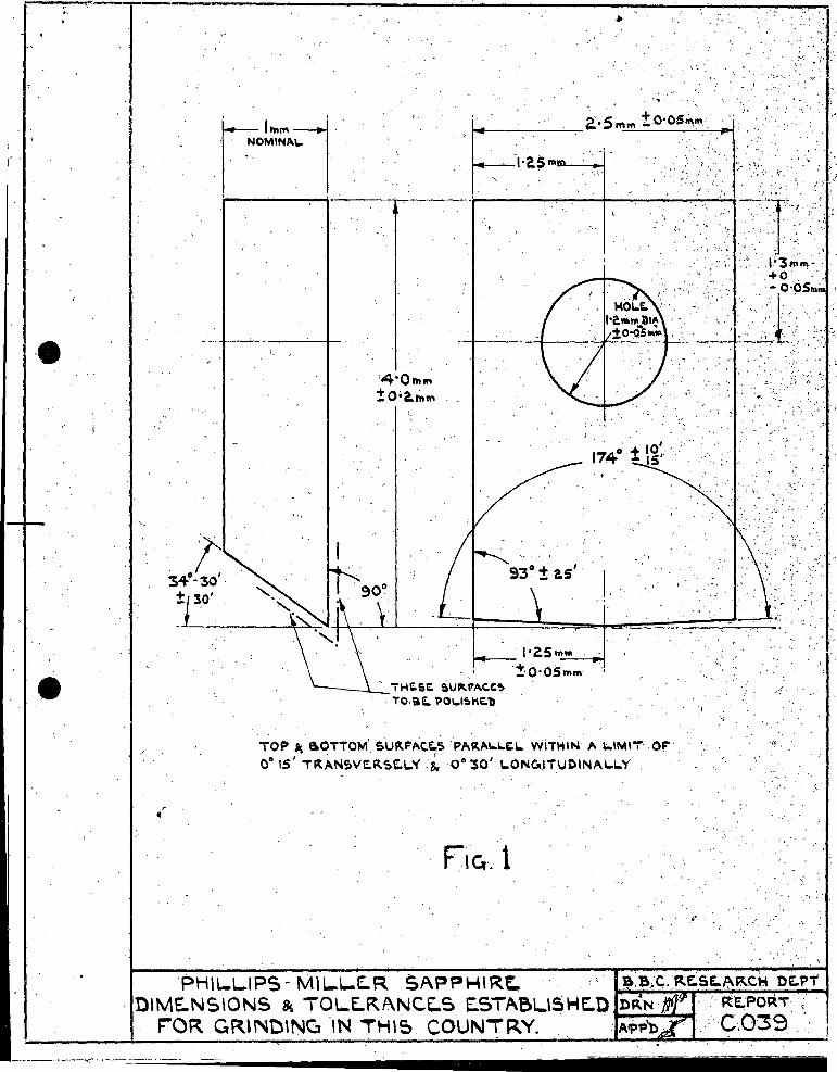
It had been decided that the modulating angle 2 x 87 0 , should be correct to within + 00 .10' and - 00 .15', in order that the signal output should be materially the same (+ 0.5 db) for all cutters, and such limits called for very special treatment. Further, that the V angle should occur symmetrically to within closer limits than were provided for in either the original Dutch cutter or the American cutt()r, imported as an emergency measure. See Fig. 1 and Appendix 2 and 3.
A ge.ometrical analysis is included in the Appendix and a draft of these findings was handed to 1fussrs Philips Cine Sonor at the outset, to ensure that the methods developed would satisfy the requirements of the Corporation, based upon measurements carried out during the past 18 months.
After some weeks of experimenting a final design for the grinding jig was evolved from the goodpolnts of the various types tried out. This jig was made in the Phll1ps armament factory at Mi tcham and called for superlative workmanship.
- 4 -
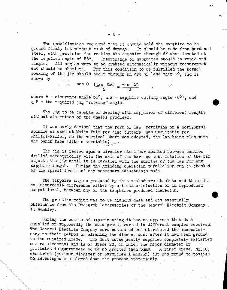
The specification required that it should hold the sapphire to be ground firmly but without risk of damage. It should be made from hardened steel, with provision for rocking the sapphire through 60 when located at the required angle of 550 • Interchange of sapphires should be rapid and simple. All angles were to be created automatically without measurement
. and should be absolute. For this condition to be fulfilled the actual rocking of the jig should occur through an arc of less than 60 , and is shown by
cos e (tan o,A) 2
= tan o..B
2
where e = clearance angle'350 , o..A = sapphire cutting angle (60 ), and a, B = the required jig "rocking" angle. e
The jig tobe capable of dealing with sapphires of different lengths without alteration of the angles produced.
It was early decided that the form of lap, revolving on a horizontal spindle as used at Maida Vale for disc cutters, was unsuitable for Philips-Miller, so the vertical shaft was adopted, the lap being flat with the bench face (like a turn ta ble ). _---
, ~
The jig is rested upon a circular steel bar mounted between centres drilled eccentrically with the axis of the bar, so that rotation of the bar adjusts the jig until it is parallel with the surface of the lap for any sapphire length. During the grinding operation parallelism can be checked by the spirit level and any necessary adjustments made.
The sapphire angles produced by this method are absolute and there is no measureable difference either by optical examination or in reproduced output level, between any of the sapphires produced therewith.
The grinding medium was to be diamond dust and was eventually obtainable from the Research laboratories of the General Electric Company at Wembley.
During the course of experimenting it became apparent that dust' supplied of supposedly the same grade, varied in different samples received. The General Electric Company were contacted and attributed the inconsist~ ency to their method of cleaning the diamond dust after it had been, ground
, to the required grade. The dust subsequently supplied completely satisfied our requirements and is of Grade 20, in which the major diameter of particles is guaranteed to be no greater than 3J.lIns. A finer grade, No. 10, was t~ied (maximum diameter of particles 1 micron) but was found to possess no advantages and slowed down the process appreciably.
- 5 -
Messrs Phi11ps Cine Sonor gained access to a diamond cutting works in London under Government control and arranged to hire one of their professional machines with a view to purchase should it prove satisfactory. This machine was installed at Maida Vale but was entirely unsuccessful, nor did it appear amenable to modification, so the idea was scrapped.
One good point did arise however, from the loan of this machine, which had been designed primarily for grinding diamond surfaces anq. was fitted wi th iron la ps.
It is most necessary that a lap shall be removable with its shaft so that when occaSion arises it may be re-surfaced in the lathe. The professional machine employed lap shafts with tapered ends (hardened steel) these ends seating between blocks of Lignum Vi too. This method has been adopted in the machine now in use (which was built from parts made in the Philips factory), and has proved entirely successful althougr a modified lubrication system has been found necessary.
The lap was a major problem. It will be readily appreciated that primarily, the surface should be absolutely flat and under the rotation called for (about 2,000 r.p.m. was found most suitable) no vibration should be set up. The surface should be smooth to avoid violent impact with the sapphire being ground, at the same time it must be capable of holding the diemond dust.
Various lap materials were tried including boxwood, satinwood, partridge vlOod, ebony, bakeli te, Arkansas Stone, iron copper and Lignum Vitae.
The metals were ,too fierce and generated too much heat, causing chipping, and,the same applied to bakelite. The fibres of boxwood available parted under the surface tension and centrifugal force. The satinwood was too soft and tended to develop unwanted radii at the facet edges, see Appendix. Partridge wood crDcri:ed during drying, as also did the samples of ebony tested. Arkansas Stone behaved rather like the metals and eventually Lignum Vi tre was decided upon, the lap consisting of a slice cut transversely 'With the trunk of the tree, presenting a face of "end wood". Slab cutting does hot appear to be suitable. This wood is difficult to obtain in diameters greater than six inches, but it was found satisfactory if the finished lap were not less than about five inches in diameter.
A method of preparing the lap was mentioned by Mr. F. C. Giddy of Maida Vale, and waS tried out, although the method was not in use for grinding the disc cutters.
- 6 -
After being turned accurately on its spindle and smoothly faced, the lap was mounted in the machine and given a fine coat of spirit lacquer. When dry, a second coat was applied and before this had time to dry, the diamond dust was rubbed into the surface. This worked quite well and after a few sapphires had been ground the lap developed an almost mirror-like surface. However, it was found that this smooth surface rather prevented the dust from remaining on the lap for any length of time, so a small quantity of fine oil was applied to the lacquered surface. The oil had two effects. It greatly augmented the adhesion of the,dust, thus preventing its removal during grinding, and at the same time speeded up the process very considerably. This was the method used to produce the test cutters referred to below.
Various speeds were tried including 1,000, 2,000 and 4,000 r.p.m, and 2,000 gives the best all round results. The power is derived from a i h.p. single phase motor and drive is ty flat endless belt.
During the last few weeks (February-March 1943) 115 test sapphires have been in use at Maida Vale and in many cases these cutters have recorded more than one reel of film. It is normal in Philips-Miller to use a sapphire for one reel, of film only. In one instance ten reels were cut with a sapphire before the slightest signs of deterioration were observable, confirming a prior conclusion (see Appendix) that absolute sharpness (an absence of spurious radii) was the ideal to be achieved. Since the issue of these cutters there has been an absence of "8" splitting and amplitude distortion, confirming the deduction arrived at mathematically that "S" spli tting, when not I incoming I, was due to an incorrect back angle coupled with the asymmetrical phase load caused by radii at the cutter blade.
Precisely similarmathods are applicable to the grinding of cutters from pristine sapphire blanks, it being important that the blanks be of ~ synthetic, not natural sapphire.
It is considered that the cutters produced by this method are equal in every way to the best Dutch and knericanproduct, and it is to be noted that no artifice had been resorted to in obtaining the exceedingly sharp yet absolutely continuous cutting edge. By I artifice I is meant the grinding of a radius at the cutting edge to give reinforcement of the sapphire material under stress.~The Dutch tried such methods in the period 1938-39 and the result ~s amplitude distortion.
Q.uite apart from the mere ability to grind sapphires as required, it is necessary that the lap should withstand the wear and tear of grinding cutters in large numbers without deterioration of its surface. This is an important point, because up to the time of the production of 115 test sapphires, Lignum Vitae appeared to be the only natural material with the desired properties.
- ? -
Much of the 'art' of the orthodox lapidary is expended in overcoming the physical limitations of the materials he uses, hence the craft is based upon experience in counteracting the infinitely variable, in short it depends upon tradition rather than upon scientific analysis, This is all very well when the aim is to produce a work of art such as an ornamental stone, but is not to be tolerated when mass-production of a geometrically precise article is required.
Lignum Vitae is one of the rare woods, .being especially difficult to obtain in war time, and generally speaking the same applies to all useful lapping timbers. Besides, no two pieces of the 'same' wood are alike in all respects - one of the infinitely variables. It was therefore decided to make a life test of the lap. It will be remembered that in addition to the wear and tear of the, 'surface and the ef,fects thereon of the heat generated by grinding, the lap is subject to centrifugal force which tends to break down the adhesion of its fibres.
A further 100 cutters were lapped and there were signs of slight deterioration in the form of fine fissures, which tended to spread radially over the lap face. After a total of 250 sapphires had been ground it was decided to re-surface the lap by turning in the lathe, because
. irregularities had'reached the sta~e where slight visible chipping of the sapphire was evident. Upon examination it was apparent that the fissures were.not a surface phenomenon but extended throughout the thickne~s of the lap, in other words the fault was mainly due to loss of fibrous adhesion as a result'of high-speed rotation.
NOTE. Throughout these experiments it had been borne in mind that the idea of a perfectly reguler surface was an abstraction - an ideal rather than a possibility. The sub-normal dimension in which continuity of the cutting edge was required to exist (wi thPhilips-Miller), no matter how fine- the diamond dust nor how apparently good the lap surface, called for a condition in which the facet under treatment should look-in to an "average" condition of the surface. Circumferentially this proviso is satisfied by rotation of the lap, the condition then being "average" for a width equal to the width of the facet;but within the dimension in which we were working,relatively mountainous irregularities might occur within the small ring of lap surface then used.
It is apparent that to obtain a truly average condition, the facet should be moved along the radius of the lap whilst grinding .is in progress. This had become evident at an early stage. The lapidary calls it polishing. '1;'he Iffect appears to be rather more complex than the mer. e attainment of anrverage grinding surface. There is good reason for believing that tnere occurs a transference of molecules from one part of the
- 8 -
faoet surfaoe to another without detachment. ",flow" •
The sapphire appears to
The expedient of shrinking a metal tyre on the lap periphery had been considered as it was thought that this might tend to restrict the radial expansion giving rise to the fissures. The matter was not proceeded with mainly owing to the difficulty of obtaining a perfectly balanoed lap if a tyre were added.
It was decided that natural timber, however well it might behave in its pristine state, was too unstable to be commercially expedient, so further investigation of possible lap material was undertaken.
"Distrene lt behaved well, though owing to its low melting point, it is difficult to turn in the lathe, requiring careful cooling. It showed no adverse effect during grinding however, but was objectionable for the purely practical reason that it produoed a high-pitched, rather ear-splitting noise when grinding was in progress, and was thus rejected on psyohological grounds.
Eboni te was good whilst it lasted, but the surface rapidly deteriorated and grinding was accompanied by an objectionable smell of rubber. Two examples of plasticised woods were then tried. "JicwoodVY was obtained by Messrs Philips Cine Sonor and "Hydulignum" via Research Department. Both e were at least equal in all respects to Lignum Vitae with the additional advantage of being almost silent under grinding. Of the two, ''Hydulignum'' was the better, and in fact appears to be the ideal material. In the results obtained it is even better than Lignum Vitae, and shows no tendency to break down. These materials are of finely laminated hard wood, and during manufacture are very highly compressed and impregnated with plastic. The specific gravity of "Hydulignumll is approximately 1. 35, and it is immensely strong and hard. Messrs Philips Cine Sonor have decided to stabilise on ''Hydulignum''.
Throughout these tests, each sapphire produced had not only been examined microscopically, but had been mounted in a cutter-head and a sound track modulation test recorded. Upwards of 1,500 cutter edges have been examined in this manner.
- 9 -
The magnificatio~ factor of the Philips-Miller cutter has already been mentioned.. The magnification provided by' the liluminatedmicroscope with which a sound test is examined as a matter of routine prior to a recording, is approximately 40 times.
The depth of a chip is not amplified by the modulating angle of the cutter,but the length of a chip appears about 20 times larger on the sound track than it occurs on the sapphire. A chip which is only just visible on the sound track cannot readily be seen by direct microsco.pic examination; that is why the cutters were given a modulation test before being issued.
It is known that American cutters are separately polished after grinding. Great care has to be exercised in polishing to prevent the occurrence of prohibitive radii. It is easy to produce chip-free cutters by polishing, where .8 comparatively large radius .is permissible. In short, a radius is a commerci?l expedient to increase production.
In most of the American Philips-Miller cutters examined, the effects on the facet planes due to polishing were invisible by shSdowgraph under a magnification of 250. Indirect methods of observation were necessa~J, such as the slow orientation of the facet in a beam of light. With a complete absence of radius et the facet edge, illumination of the whole facet was instantaneous at a particular degree of orientation, whilst the microscopic radius at the cutting edge of the American sapphires under orientation gave rise at one instant to a fine line of reflected light from the edge, prior to complete reflection from the whole facet.
Amongst the sapphires issued for test purposes, apart from the 115 already mentioned, were some polished on the American lines. Special coding has enabled the results to be analysed, and no practical disadvantage has been found either in quality of recording or useful life of the cutter edge, but on the initial modulation test prior to issue the acceptance figure for polished sapphires was 9~ and for unpolished, 6d%.
LaRmaterial,s< for pol~l3hing :which have been tried out are as follows '. """",'
t. I .. Viash Leather Hard satinwood Pitch Velvet
The leather was glued to 8 wooden lap which had been previously trued in the lathe, and 8 small quantity of diamond dust was rubbed into the surf8ce. It polished satisfactorily but ground a radius too readily, with the additional disadvant8ge .that much leather-dust was created, which was likely to be injurious to the operator. .
- .10 -
Hard Satinwood \Alas quite good for about fifteen cutters, after which the hair-like surface was destroyed, and the lap had to be re-faced.
Pi tch is probably an ideal material for the purpose but it is always in a partially fluid condition even at normal room temperature. Because of this, under rotation, vortices are created causing funnelling of the surface, so precluding the attainment of the accurate geometry necessary without elaborate methods of cooling.
A high:g;~d.e velvet of fine texture was glued ,to ~h!~~d'~urate' hardwood lap. With an extremely sma 11 quantity of diamond dust ,thi s behaves very well, and duplicates the condition found in the American cutter. The polishing process takes about 10 seconds. A certain amount of skill is e necessary, the cutter contacting with the surface nap, without pressing down upon the hard oase, but this aspect of the commercial production of Philips-Miller cutters does not .necessarily represent finality, although the results are highly successful, and there appears to be no deterioration of the nap surface.
The transfer of the process from a "test" condition to a production. basis is, of course, the concern of Messrs Philips Cine Sonor, but it is reasonable to assume that no difficulty should be experienced in maintaining the standard of the cutters produced, thereby satisfying the somewhat stringent tolerances required to meet Corporation needs.
- 11 -
APmNDIX 1.
General Remarks
The problem of grinding or regrinding the sapphire cutter consists of
. (1) The creation of correct angles, both apical and "clearance" (2) The margins of the facets being continuous, i.e., without
irregularities, and combining these qualities with (3) An absence of spurious radii at the apices of the cutter.
In this latter respect the requirements are different from those met with by the lapidary in dealing with precious stones for ornamental purposes, where the existence of radii at the margins of the facets is not necessarily detrimental. Nor is the orthodox lopidary called upon to work to within less than 10 of arc.
The Philips-Miller cutter is especially difficult to produce because of the obtuse "modulating'? angle -: 1740 , which must be correct, the slightest departure from this angle giving rise to marked change in recorded amplitude with consequent change in reproduced level, whilst enlargement of the prescribed back angle - 550 - mey cause amplitude attenuation and distortion in wave shape of the higher frequencies.
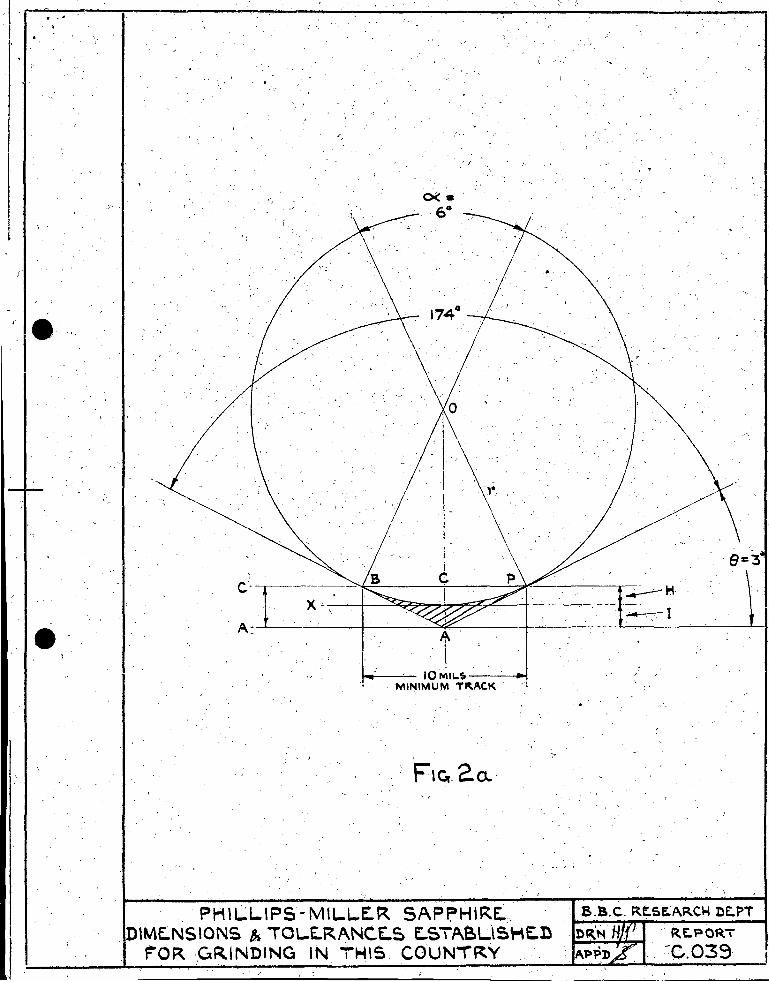
A radius may exist in a variety of different ways. Fig. 1 illustrates the ideal cutter in which there is an absence of radii at the modulating and cutting apices, and maximum manufacturing tolerances are indicated.
Fig. 2a shows the effect of El radius at the modulating apex and as an unavoidable corollary of this condition, the occurence of a radius at the apex of the back slope,Fig. 2b. These are merely two aspects of the same phenomenon, though it is to be noted that their effects upon the sound characteristics recorded are very different. It is further apparent that a given radius at the back face,Fig. 2b,- implies a very much larger radius at the modulating apex,Fig. 2a, the relationship being a function of the angular ratio a.: e
Fig. 2c illustrates a radius at the front face and Fig. 2d a combination of the conditions 2b and 2c. Ex:periment has shown that neither of these is tenable with Philips-Miller. The existence ofa facing radius producing vertical oscillation of the cutter, and therefore a saw-toothed demarcation between the opaque and transpa·rent strata of the film. We shall. confine ourselves accordingly, to the consequence of conditions illustrated in Figs. 2a and 2b respectively.
- 12 -
The effects of such radii are complex because three distinct defects may be introduced.
Case A. vr.~ere the radial curvature extends along that part of the cutter used for modulation, gives rise to a non-linear relationship between signal input and resulting modulation (this occurs at the apex of the V angle - 1740 )) and since it is impossible for a radius to exist in only one plane of the cutter a second radius is automatically created at the apex of the back slope and this may give rise to cases Band C. ---Case B. In which there is interference between the back face and the gradient of the recorded wave-form, produces distortion of wave shape. Again this happens if a radial curvature (concurrent with Case A) exists ate that part of the back face of the cutter used for modulation. Theoretically then, the limits of possible radii are where the curvature ends at that height from the apex which is normally submerged in the gelatine stratum in produc ing minimum wi d th of track in the opaque skin (1. e., in a condi t ion of zero signal input). It will be observed that case B is tantamount to increasing the back angle - 550 •
Case C. As the cutter must perform work in engraving the film, the limits of radius to satisfy these theoretically correct modulation' characteristics do not hold in practice. Such a radius constitutes a physical blunting of the cutter, and in view of the "hill and dale" nature of the recording, the "penetration" load is greatly increased (notwithstanding the stiffness of the cutter-head armature axis) giving rise to severe asymmetrical amplitude distortion, Case C.
(I)
APPENDIX II
GEOMETRICAL TREATMENT.
In order that the magnification factor shall be the same for all sapphires - 2tan !~= 38.16 - the modulating angle 1740 must be preCise, ensuring consistency of Signal output for a given signal input to the cutter-head, for different sapphires. Allowing an output tolerance of + 0.5 db, the angle 1740 must be exact to within + 0°.10' - 00.15' of arc (approx.)
(2) The back angle of the cutter should be 550 (1. e., a clearance angle of 350 Fig. I), but for the purpose of establishing tolerance limits may be taken as 54.50 + 0.50 , so that the angle will never be less than 540 (to guarantee the strength of the cutter blade under load), and more especially never greater t~an 550 to ensure absence of wave shape distortion of the upper frequenc'fes when recorded at the maximum amplitudes called for.
- 13 -
(3) The apex of the V angle 1740 should have no ,discernable radius when examined under a microscope with a magnification of 400 diameters. The existence of a visible radius under these conditions may produce Case A, non-linear relationship between the impressed "vertical" Signal and the resulting horizontal component inscribed in the opaque film stratum. Casu A may exist where the radial curvature extends above that part of the V cutter blade which is normally submerged beneath the black layer in the production of minimum (squeeze) track, ignoring for the present instance the opening time-lag of the GNR system, which results ,in modulation occu~ng about the minimum at the moment of impact signal.
The following is based upon the assumption that squeeze track is no greater than 10 mils Wide, though the condition is empirical, depending as it does upon concentricity of the recording drum, and consistency of the film strata thicknesses.
Referring to Ffg.2a, the angle 1740 is not drawn to scale. The shaded portion BAP represents that part of the sapphire ground away in the creation of radius OP. ~-'-
, ' '" ........ . ',' With apical angle 1740 and chord BCP equal to the width of average
squeeze track (10 mils) , the ratio depth of cut to inscribed horizontal width is constant for all modulation above squeeze track, so that neglecting the opening time-lag of the ground-noise-reduction system, no distortion due to the non-linear function of curve BP exists. For this condition to be fulfilled the height AC must not exceed the value given by
0.262 mil.
where the Cd. BCP = average minimum track = 10 mils.
If the height AC, and therefore the chord BCP were increased, then distortion due to Case A would arise unless the width of minimum track were proportionately enlarged.
The cutting angle e is equal to ia. for any radius OP and any value of e Since e = 3 0 , and the chord BCP ~ 10 roils, (squeeze track width), the radius OP is shown by
1 ~.£.~. = sin e 95.602 mils = radius
- 14 -
To evaluate H it is necessary to discover the value QC. OC is equal to r(cos e} = 95.468 mils, so that H = 0.134 mil, being the height of chord BCP with radius OP when BCP = 10 mils.
Expressed differently, the chord BCP = 2 sin (~) and H =l-cos (CL) where r = 1. 2 2' . The occurrence of radius at the maxinru.mto satisfy Oase A·wl)uld mean that'tlie cutter blades submerged in producing, sq1i~ez'e track would possess a higher I.J. factl)r than the upper slope of the blades, and this would call for even greater precision of bearings, recording JIl drum, etc., to maintain a constant squeeze track width. ..,
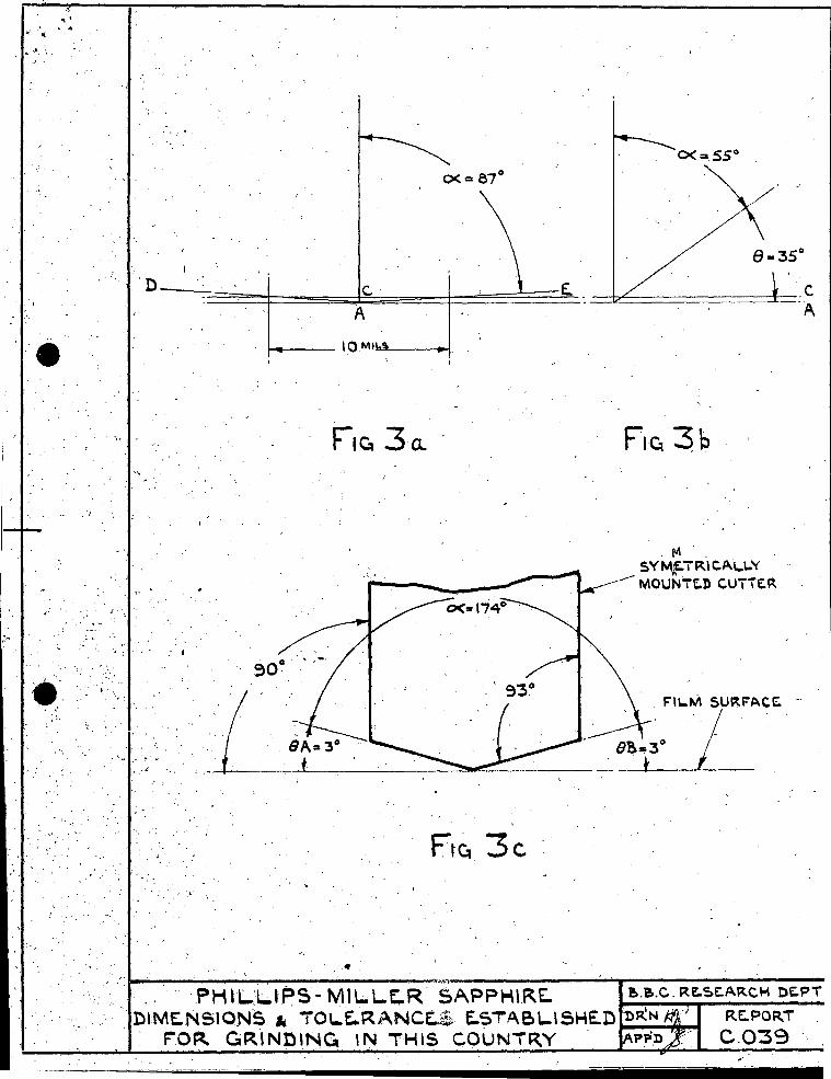
(4) The back angle 550 should have no discernable discontinuity at the apex A (Fig.3b) throughout the length of the V cutting edge DAE (Fig.3a) since inconsistency ~f,the cutting edge sharpness would produce variation of load with amplitude (Case C). whilst unevenness or chips in the blades would result in discontinuity of inscribed wave contour and therefore harmonic distortion in reproduction. Any radius at the apex of the back angle 55°, (concurrent with a radius at the apex ~f the modulating angle 174°). which extends beyond that height 9ft]::te sapphire subm8rged in the gelatine stratum in a conditif'n nfI\l;i,~.:i:m~ track, results in distortion of wave shape (Case B) ,being sinif~a:r,. :tn, effect to an enlarged back ~
An avera~e minimum track of~tO mils width has been shown to require a penetration of height AC, eQual to
10 = 0.262 mil (Figs.3a and 3b)
Referring t~ Fig.2b, which illustrates a cross-section of the sapphire with back angle 55°, the length CP is e(lual to
AC (tan a. ) - 0.374 mil
Therefore the length AP is eClual to
\1 'I
.; (CP ) 2 + (AC ) 2 0.456 mil.
T~e maximum ~ermissible Case B is shown by
radius OP at the back face AP to satisfy
OP = _O_C_= cos e
CP
sin El
- 16 -
== ~374 0.5736
= 0.652 mil.
In this condition the radius at the apex of angle 1740 has been shown to be 95.602 mils. This occurs when the shaded area XPA, Fig.2b, is ground away in forming the radius OP, and is J?ormissible for the elimination of Case A, but is prohibitive because of the high penetration load imparted by the curvoPX when inscribing relatively high frequencies.
It follows that merely to satisfy the requiremimt for the elimination of that type of distortion due to Case A, when the minimum track is no smaller than 10 mils, makGs J?ossibli3 the creation of a relatively large radius at the apex of the angle 1740 , so distortion of this kind is not normally experienced in practice; out with such a radius there exists also the radius OP = 0.652 mile at the back face, ~. Under 'these conditions the penetration load would be excessive due to the extremely asymmetrical phase load created. It is a~parent that a radial condition at the apex of the angle 1740 may be such as to exclude distortion due to Case A, whilst distntion of Case C may still be present because of the cyclic incremont of penetration load during incursion,of the sapphire. Such increase of the load by a radius at
'the apex is a constant and therefore increases proportionateiy with frequency for a given amplitude. Hence, whilst the effect may be
'negligible at relatively low frequ2ncies, it may become prohibitive at the higher frequencies', and r8sul ts in the characterist ic symptoms
. of what is commonly known as a "blunt" sapphire.
Such defects were obsorvable in many Dutch sapphires supplied during the .period 1938-1939. It is known that the deliberate creation of radius was attempted by the Dutch (a) to simplify the acquisition of a continuous" sharp edge, and (b) to strengthen the material of the cutt~r under stress, but such a procedure is not recommended and the edge should be continuous and sharp. without the artifice of creating spurious radii to strengthen the m<;>,dula ting blade.
, ~
It is kno~m that chipping during recording occurs not because of normal wear and tear, but due to the impl'l.ct of foreign particles in the film emulsions.
Chippin2, is normally of a microscopiC nature (of the order of l/lOO,OOOth inch) and can give rise to audible distortion only when the results are readily observable on the sound track under normal powers of magnification (x 40).
;- .~
- 16 -
The dOwree of harmonic distortion produced by a chip of given length and depth is a function of the magnification factor of the cutter in relation to the thickness of the opaque layer (3 ~;ns). I~ any case, the audible distortion produced by such chipping as may occur during a recording is infinitely less than the amplitude distortion which results from a radius,large enough to be measurable by normal methods.
APFENDIX HI ° The effect of asymm~t..ric,"'l mounti~ where CL= 174 absolute