78
Requirements Modeling and Use Case Diagrams Instructor: Dr. Hany H. Ammar Dept. of Computer Science and Electrical Engineering, WVU
| Date post: | 31-Dec-2015 |
| Category: |
Documents |
| Upload: | norman-moody |
| View: | 219 times |
| Download: | 2 times |
Requirements Modeling and Use Case Diagrams
Instructor: Dr. Hany H. Ammar
Dept. of Computer Science and Electrical Engineering, WVU

outline
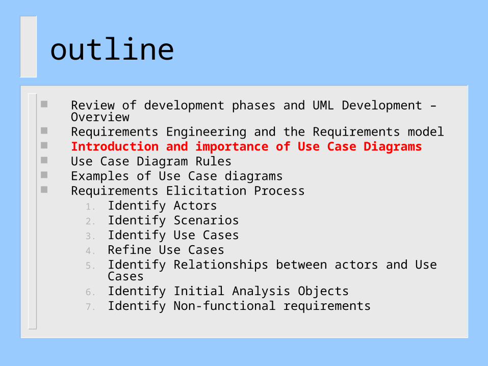
Review of development phases and UML Development – Overview Requirements Engineering and the Requirements model Introduction and importance of Use Case Diagrams Use Case Diagram Rules Examples of Use Case diagrams Requirements Elicitation Process
1. Identify Actors2. Identify Scenarios3. Identify Use Cases4. Refine Use Cases5. Identify Relationships between actors and Use Cases6. Identify Initial Analysis Objects7. Identify Non-functional requirements

Requirements: Develop the Requirements Model
Analysis: Develop the Logical Model
Design: Develop the Architecture Model
Implementation
Testing
Review: Phases of System Development
RequirementsEngineering
Engineering Design

Workflows and Models
Requirements
Design
Implementation
Test
Analysis
Use CaseModel
DesignModel
Depl.Model
Impl.Model
AnalysisModel
TestModel
UML diagrams provide views into each model
Each workflow is associated with one or more models.

Use Case ModelUse CaseDiagrams
CollaborationDiagrams
ComponentDiagrams
DeploymentDiagrams
ObjectDiagrams
StatechartDiagrams
SequenceDiagrams
ClassDiagrams
ActivityDiagrams
Use CaseModel
DesignModel
Depl.Model
Impl.Model
AnalysisModel
TestModel

Analysis & Design ModelUse CaseDiagrams
CollaborationDiagrams
ComponentDiagrams
DeploymentDiagrams
ObjectDiagrams
StatechartDiagrams
SequenceDiagrams
ClassDiagrams
ActivityDiagrams
Use CaseModel
DesignModel
Depl.Model
Impl.Model
AnalysisModel
TestModel
Incl. subsystems and packages

Deployment and Implementation ModelUse CaseDiagrams
CollaborationDiagrams
ComponentDiagrams
DeploymentDiagrams
ObjectDiagrams
StatechartDiagrams
SequenceDiagrams
ClassDiagrams
ActivityDiagrams
Use CaseModel
DesignModel
Depl.Model
Impl.Model
AnalysisModel
TestModel
Incl. active classes and components

UML Development - Overview
PROGRAM
ACTORS
ANALYSISSpecify Domain Objects
Detailed DESIGN
IMPLEMENTATION
DATA
DICTION
ARY
TimeUSE CASES
ANALYSISCLASS DIAGRAM(S)
IMPLEMENTATIONActivity DIAGRAMS
System/ObjectSEQUENCEDIAGRAMS
OPERATION CONTRACTS
StateChart DIAGRAMs
DEPLOYMENT DIAGRAMSUBSYSTEM CLASS/OR COMPONENT
DIAGRAMS
Architectural DesignIncludeDesign Objects
ObjectDesign
SCENARIOS
REQUIREMENTSELICITATION
DESIGN DIAGRAMS
IMPLEMENTATIONCHOICES
DESIGN SEQUENCE DIAG.
RequirementsEngineering

outline
Review of development phases and UML Development – Overview Requirements Engineering and the Requirements model Introduction and importance of Use Case Diagrams Use Case Diagram Rules Examples of Use Case diagrams Requirements Elicitation Process
1. Identify Actors2. Identify Scenarios3. Identify Use Cases4. Refine Use Cases5. Identify Relationships between actors and Use Cases6. Identify Initial Analysis Objects7. Identify Non-functional requirements

What is Requirements Engineering ?
Requirements Engineering

What is Requirements Engineering?
Requirements Management:Requirements management activities include evaluating the impact of proposed changes, tracing individual requirements to downstream work products, and tracking requirements status during development
Several Requirements management tools are available in industry

What is Requirements Engineering?
Major Requirements Management Tools:http://www.capterra.com/requirements-management-software
1. Caliber-RM by Technology Builders, Inc.; www.tbi.com
2. RequisitePro by Rational Software Corporation; www.rational.com
3. RTM Workshop by Integrated Chipware, Inc.; www.chipware.com
What is Requirements Engineering?
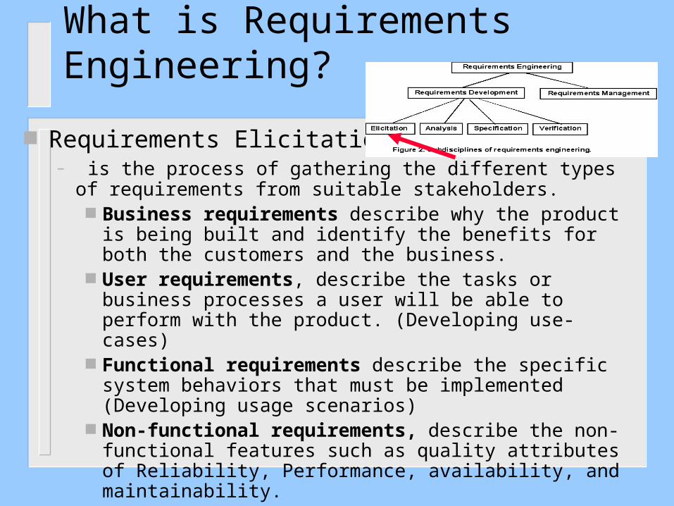
Requirements Elicitation – is the process of gathering the different types of requirements
from suitable stakeholders. Business requirements describe why the product is being
built and identify the benefits for both the customers and the business.
User requirements, describe the tasks or business processes a user will be able to perform with the product. (Developing use-cases)
Functional requirements describe the specific system behaviors that must be implemented (Developing usage scenarios)
Non-functional requirements, describe the non-functional features such as quality attributes of Reliability, Performance, availability, and maintainability.

What is Requirements Engineering?
Requirements analysis:Requirements analysis includes decomposing high-level requirements into detailed functional requirements, constructing graphical requirements models or logical models (structured Analysis models, or Object-Oriented Analysis models) (for developers), and building prototypes.
Analysis models and prototypes provide alternative views of the requirements, which often reveal errors and conflicts that are hard to spot in a textual SRS.

What is Requirements Engineering?
Requirements Specification Specification key practice is to write down the
requirements in some accepted, structured format as you gather and analyze them.
The objective of requirements development is to communicate a shared understanding of the new product among all project stakeholders.
Historically, this understanding is captured in the form of a textual SRS document written in natural language, augmented by appropriate analysis models. (to be discussed in detail)

What is Requirements Engineering?
Requirements VerificationVerification involves evaluating the correctness, completeness, unambiguity, and verifiability of the requirements, to ensure that a system built to those requirements will satisfy the users’ needs and expectations. The goal of verification is to ensure that the requirements provide an adequate basis to proceed with design
Prototyping (or executable specifications) is a major technique used in verification. Examples include GUI development for user requirements verification, and Formal requirements specification environments

Requirements Engineering:The Requirements Model
Static Analysis Dynamic Analysis
Functional/ NonfunctionalRequirements
Use Case Diagrams/Sequence Diagrams(the system level)
- Class Diagrams- State Diagrams/Refined Sequence Diagrams (The object level)
The Requirements ElicitationProcess
The Object-OrientedAnalysisProcess
Problem statement
outline
Review of development phases and UML Development – Overview Requirements Engineering and the Requirements model Introduction and importance of Use Case Diagrams Use Case Diagram Rules Examples of Use Case diagrams Requirements Elicitation Process
1. Identify Actors2. Identify Scenarios3. Identify Use Cases4. Refine Use Cases5. Identify Relationships between actors and Use Cases6. Identify Initial Analysis Objects7. Identify Non-functional requirements
Use Case Diagrams Introduction and importance
Use cases are widely regarded as one of the important artifacts needed to successfully develop complex software systems
Use cases define the scope of the system and clarify the behavioral system requirements

Use Case Diagrams Introduction and importance
Provide a basis for a coherent conceptual understanding of the system under consideration without requiring knowledge of software design or implementation technology
Used as organized means of capturing domain expertise

Use Case Diagrams Introduction and importance
Can be used to track the progress of the system development effort
Provide means to trace requirements to the design
Provide the basis for developing system acceptance tests

Use Case Driven
Req.ts Impl. Test
Use Cases bind these workflows together
Analysis Design

Use Cases Drive Iterations
Drive a number of development activities– Creation and validation of the system’s
architecture– Definition of test cases and procedures – Planning of iterations– Creation of user documentation– Deployment of system
Synchronize the content of different models


Use Case Diagrams Introduction and importance
The identification of use cases and actors occurs during the initial requirements analysis phase of a project
The use cases most essential to the system are selected, analyzed, and specified.

Use Case Diagrams Introduction and importance
These essential use cases eventually become the basis for defining the architecture of the system during the first iterations of system development
The use cases are then allocated to iterative releases, which are planned and eventually executed
Use Case Diagrams Introduction and importance
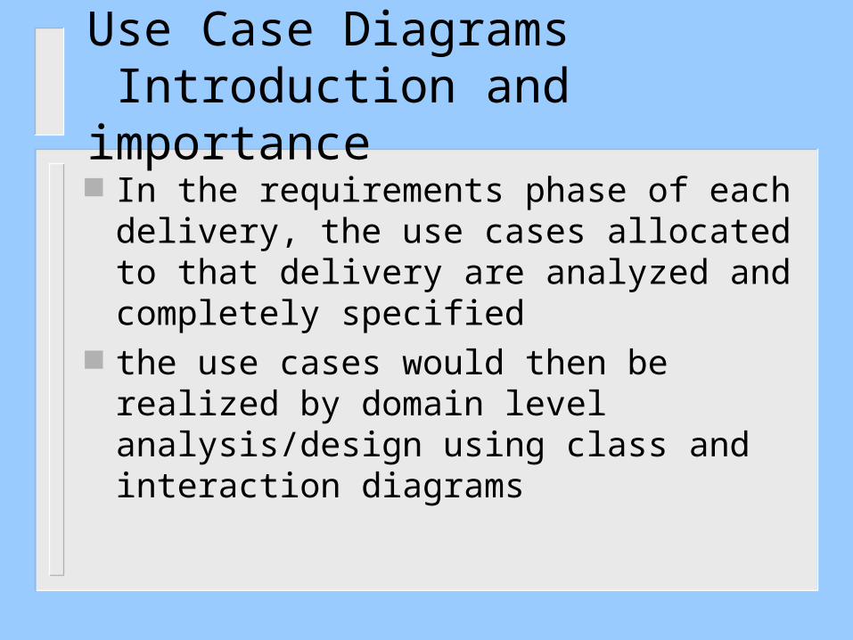
In the requirements phase of each delivery, the use cases allocated to that delivery are analyzed and completely specified
the use cases would then be realized by domain level analysis/design using class and interaction diagrams

Use Case Diagrams Introduction and importance
The domain level realization is further refined into a detailed design that typically employs class and interaction diagrams and often includes state transition diagrams and/or decision tables.

outline
Review of development phases and UML Development – Overview Requirements Engineering and the Requirements model Introduction and importance of Use Case Diagrams Use Case Diagram Rules Examples of Use Case diagrams Requirements Elicitation Process
1. Identify Actors2. Identify Scenarios3. Identify Use Cases4. Refine Use Cases5. Identify Relationships between actors and Use Cases6. Identify Initial Analysis Objects7. Identify Non-functional requirements

Use Case Diagrams
Use Case Diagram Rules – Use a “stick man” figure for an actor, and show
the actor’s name below the stick man– The UML standard allows for the option of
using a class rectangle with the stereotype «actor»
Command EndItem Hardware
User
«actor»Sensor
<<Stereotype>>

Use Case Diagram Rules The only valid relationship between an
actor and another actor is generalization
User Super User
Run Applications Install Applications
A User can Run Applications.A Super User can InstallApplications and RunApplications, since a SuperUser is a specialization ofUser.

Use Case Diagram Rules
Use only the following relationships between use cases – Use the include relationship to show that the
behavior of one use case is wholly and unconditionally used in another use case
– Use the generalization relationship to show that a use case is a specialization of another use case

Use Case Diagram Rules
the include relationship
Perform Transaction
Send Command Receive Response
Application «include» «include»
The Perform Transactionuse case includes theprocessing specified byboth the Send Commandand Receive Responseuse cases.

Use Case Diagram Rules
the generalization relationship
Validate Identity Identify by fingerprint scan
Identify by retinal scan
Identify by badge scan
Customer

Use Case Diagram Rules
Use the extend relationship to show that one use case conditionally augment (or extend) the behavior of another use case.
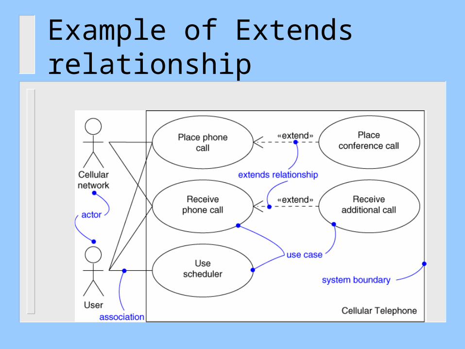
Example of Extends relationship
Use Case Diagram Rules
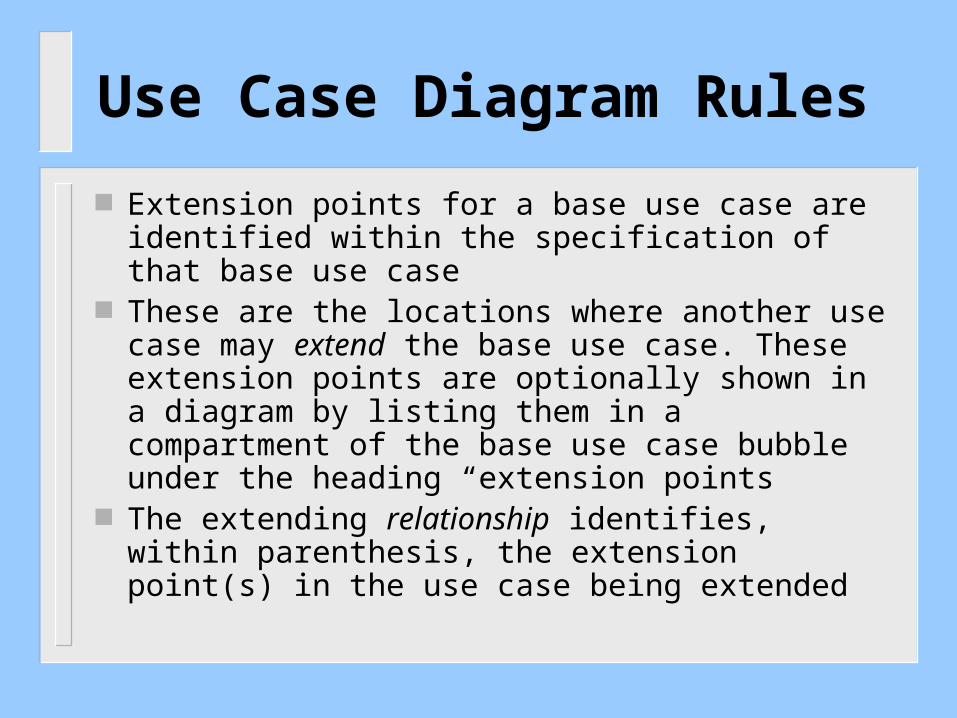
Extension points for a base use case are identified within the specification of that base use case
These are the locations where another use case may extend the base use case. These extension points are optionally shown in a diagram by listing them in a compartment of the base use case bubble under the heading “extension points
The extending relationship identifies, within parenthesis, the extension point(s) in the use case being extended

Log In
extension pt::Set Privileges
User
Grant Administrator Privledges
<<extends>>(Set Privileges)
[Administrator Login event]]
Identify, within brackets, the condition under which the extension is executed
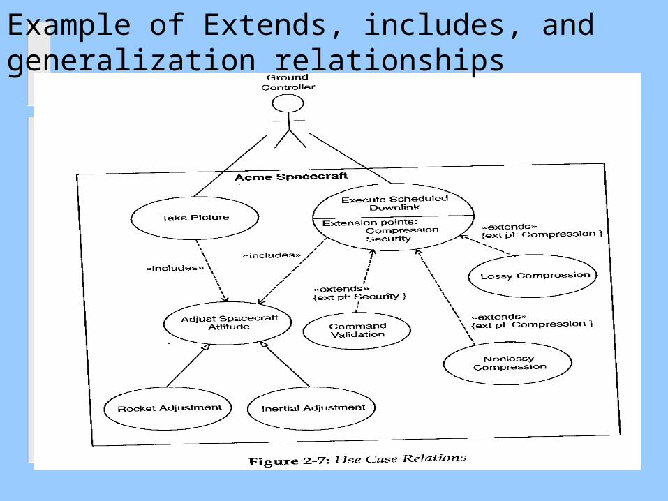
Example of Extends, includes, and generalization relationships

Use Case Diagram Rules
There must be one extension point listed for each segment identified in the extension use case
Although considered optional, it is recommended that the extending relationship also identify, within brackets, the condition under which the extension is executed

Use Case Diagram RulesUse Case Packages
Use cases are often written and organized in layers of abstractions using Use Case Packages
A use case package contains a number of actors, use cases, their relationships, and perhaps other packages
A Use Case Package
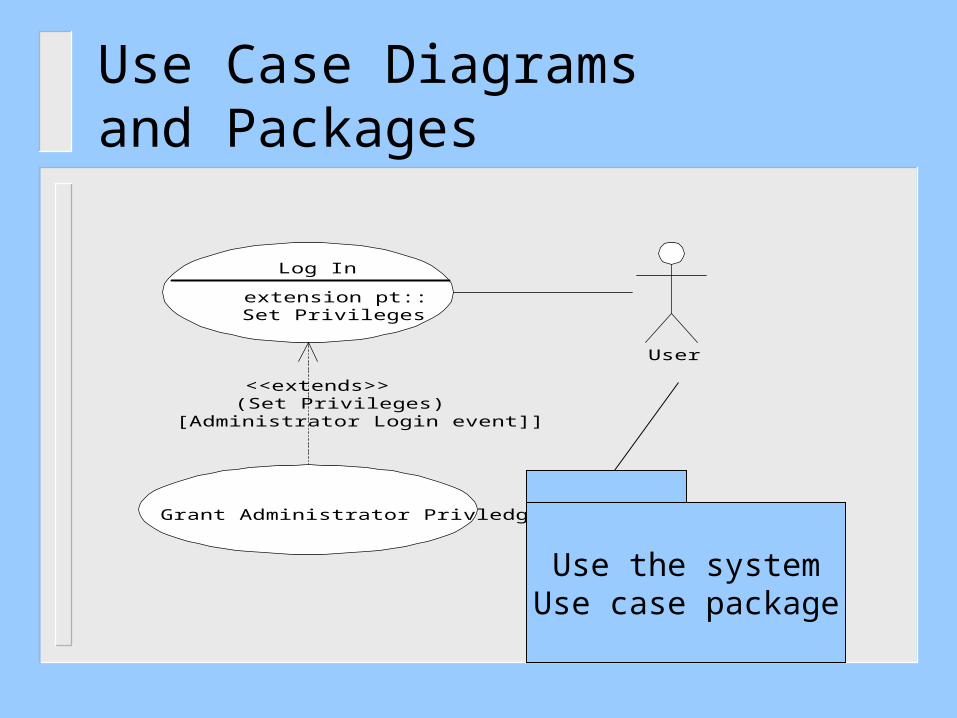
Use Case Diagramsand Packages
Log In
extension pt::Set Privileges
User
Grant Administrator Privledges
<<extends>>(Set Privileges)
[Administrator Login event]]
Use the systemUse case package

outline
Review of development phases and UML Development – Overview Requirements Engineering and the Requirements model Introduction and importance of Use Case Diagrams Use Case Diagram Rules Examples of Use Case diagrams Requirements Elicitation Process
1. Identify Actors2. Identify Scenarios3. Identify Use Cases4. Refine Use Cases5. Identify Relationships between actors and Use Cases6. Identify Initial Analysis Objects7. Identify Non-functional requirements

Examples of Use Case DiagramsExample 1: Medical Clinic Software,could be missing use case relations
Each use-case is described further by textual document and by Scenarios developed using UML sequence diagrams

Example 2: E-Commerce Application (Incomplete)Missing a link between “Place Requisition” and “Supplier”and missing use case relationships
Customer Supplier
Bank
Browse Catalog
Confirm Shipment
Process Delivery Order
Send InvoicePlace Requisition
Confirm Delivery

Example 3: Coffee Maker, “waiting state” Not a good name for a use-case (bad example)

Example 4: Anesthesia System(Incomplete)

Example 5:AutomatedAirTrafficControlSystem(AATCS)
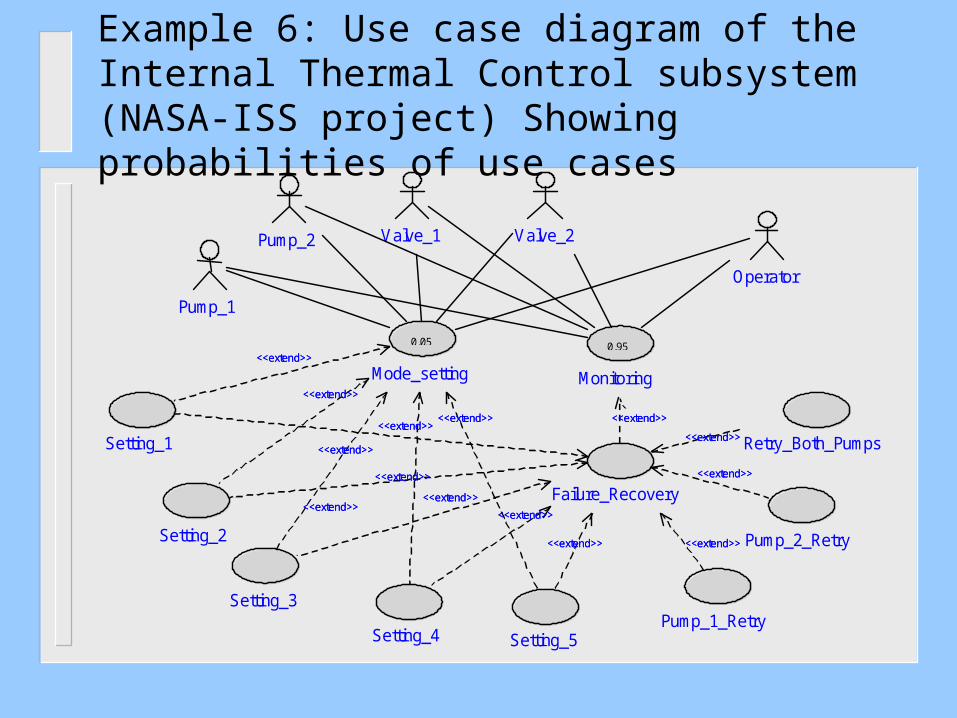
Example 6: Use case diagram of the Internal Thermal Control subsystem (NASA-ISS project) Showing probabilities of use cases
Setting_1
Setting_2
Setting_4
Setting_3
Setting_5 Pump_1_Retry
Pump_2_Retry
Retry_Both_Pumps
Valve_2 Valve_1 Pump_2
Operator
0.05
Mode_setting <<extend>> <<extend>>
<<extend>> <<extend>> <<extend>> <<extend>>
<<extend>> <<extend>>
<<extend>> <<extend>>
Pump_1
Failure_Recovery
<<extend>> <<extend>> <<extend>> <<extend>>
<<extend>> <<extend>> <<extend>> <<extend>>
<<extend>> <<extend>> <<extend>> <<extend>>
<<extend>> <<extend>> <<extend>> <<extend>>
0.95
Monitoring
<<extend>> <<extend>>
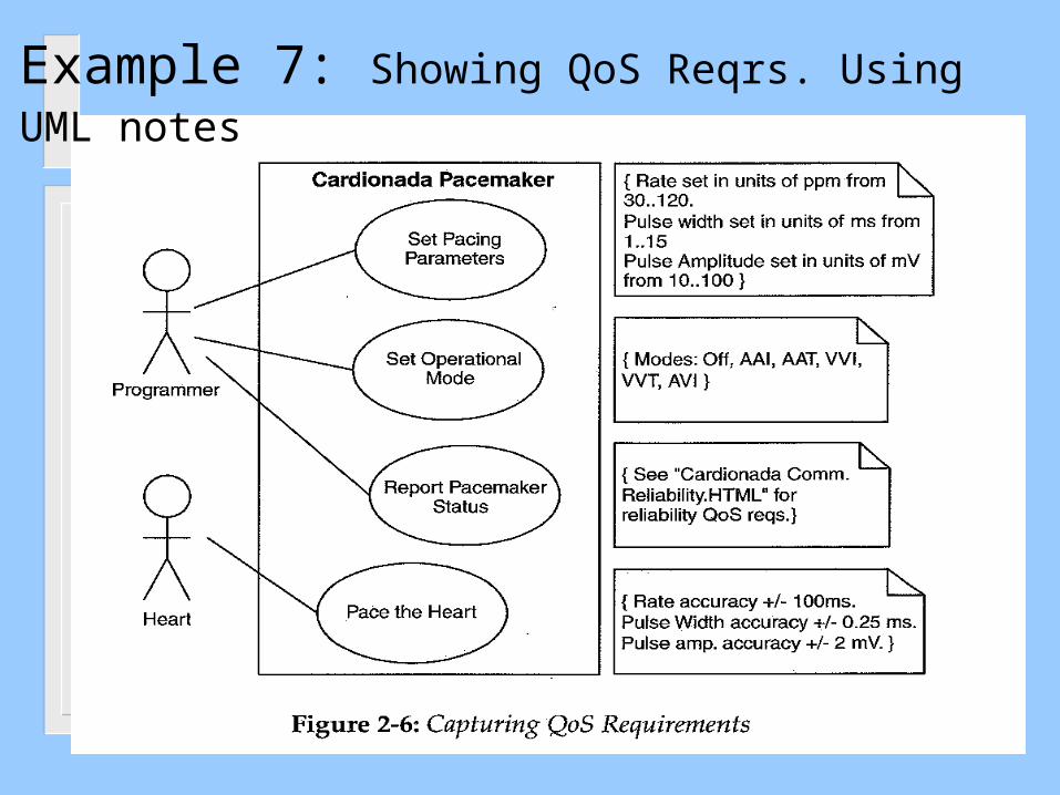
Example 7: Showing QoS Reqrs. Using UML notes

Example 8: Elevator Control System
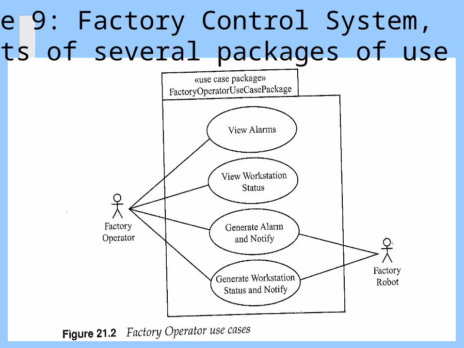
Example 9: Factory Control System, consists of several packages of use cases

Example 9: Factory Control System (cont.)

Example 10: Cruise Control and Monitoring System: Cruise Control Package

Example 10: Cruise Control and Monitoring System (cont.):Monitoring Package
Not Good Too many use cases, try to aggregate

Example 11: Airport Check-in

outline
Review of development phases and UML Development – Overview Requirements Engineering and the Requirements model Introduction and importance of Use Case Diagrams Use Case Diagram Rules Examples of Use Case diagrams Requirements Elicitation Process
1. Identify Actors2. Identify Scenarios3. Identify Use Cases4. Refine Use Cases5. Identify Relationships between actors and Use Cases6. Identify Initial Analysis Objects7. Identify Non-functional requirements

Requirements Elicitation Process
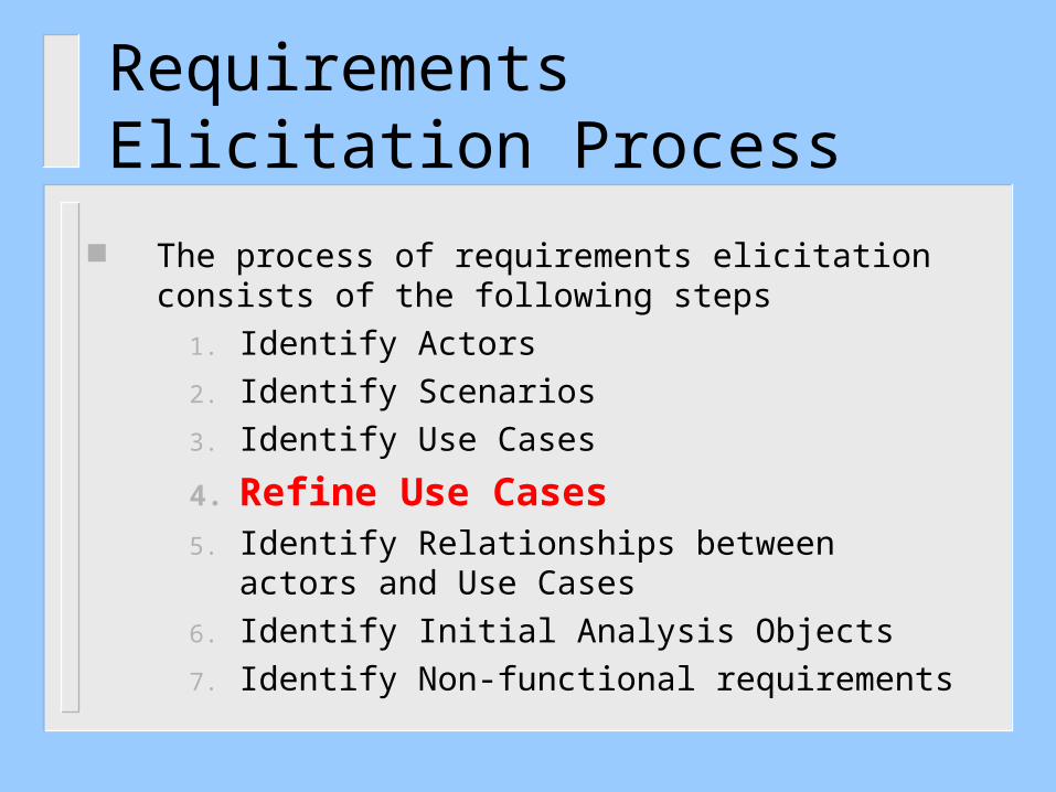
The process of requirements elicitation consists of the following steps
1. Identify Actors
2. Identify Scenarios
3. Identify Use Cases
4. Refine Use Cases
5. Identify Relationships between actors and Use Cases
6. Identify Initial Analysis Objects
7. Identify Non-functional requirements
Requirements Elicitation Process
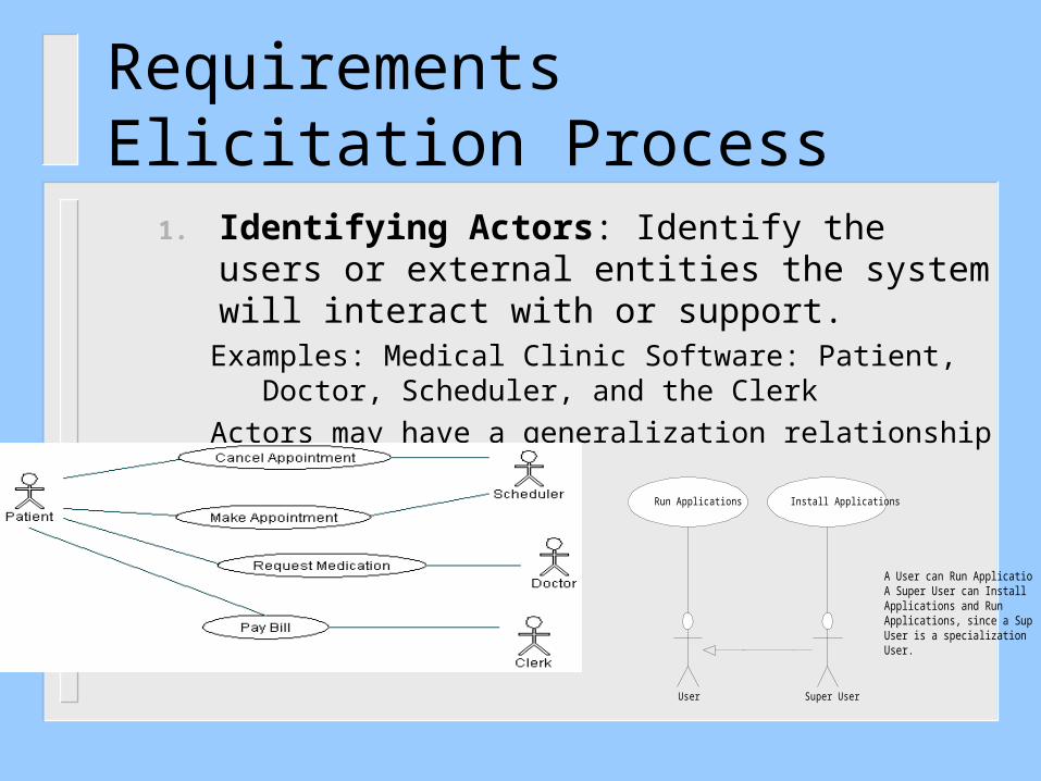
1. Identifying Actors: Identify the users or external entities the system will interact with or support.
Examples: Medical Clinic Software: Patient, Doctor, Scheduler, and the Clerk
Actors may have a generalization relationship
User Super User
Run Applications Install Applications
A User can Run Applications.A Super User can InstallApplications and RunApplications, since a SuperUser is a specialization ofUser.

Requirements Elicitation ProcessIdentifying Actors from Business process modelshttp://www.visual-paradigm.com/product/ag/tutorials/frombptouc.jsp

http://www.youtube.com/watch?v=d4_yvQwC66o
Requirements Elicitation ProcessIdentifying Actors from Business process models
Requirements Elicitation Process
2. Identify Scenarios of usage (user/actor stories): these are examples of typical user or actor interactions with the system. The are defined by a flow of eventsExample 1: Medical Clinic Software: in one scenario, the patient will contact the scheduler to make an appointment he finds an answer that office is closed, in another scenario he will contact the doctor to request medication, the doctor responds to him with the name of the medication

Requirements Elicitation Process 2. Identify Scenarios of usage (cont.)
Example 3: The Coffee Maker waits for user input. There are six options to chose from: 1) add recipe, 2) delete a recipe, 3) edit a recipe, 4) add inventory, 5) check inventory, and 6) purchase beverage, the user chooses to delete a recipe which does not exist.
Recall that the scenarios are user driven and not system driven (user perspective)
Requirements Elicitation Process
3. Identify Use Cases: Once scenarios of usage are identified, use cases are defined to model the main user-based processes of the system.
Example: identify the “Make an Appointment” use case from one scenario and the “Request Medication” from another scenario
Requirements Elicitation Process
The process of requirements elicitation consists of the following steps
1. Identify Actors
2. Identify Scenarios
3. Identify Use Cases
4. Refine Use Cases5. Identify Relationships between actors and Use
Cases
6. Identify Initial Analysis Objects
7. Identify Non-functional requirements

Requirements Elicitation Process
4. Refine Use Cases: describe the details of each use case. A Textual template is used as well as UML interaction diagrams (UML sequence diagrams or object collaboration diagrams).
Textual: Brief Description, Actors, Preconditions, Basic Flow of Events,
Alternate flow of events,
System
Sequence
Diagram
A cto r1A cto r2
S y s te m: S
S1
S2
S3
S4
E 11
L i s t o f G u i d e W o r d s
L i s t o f G u i d e W o r d s
L i s t o f G u i d e W o r d s
L i s t o f G u i d e W o r d s
L i s t o f G u i d e W o r d s
E 2 1
E 1 2
E 2 2
E 3 2E 4 1
E 3 1
L i s t o f G u i d e W o r d s
L i s t o f G u i d e W o r d s

Requirements Elicitation Process 4. Refining Use Cases (cont.) Sequence Diagrams capture scenarios (to be discussed later in slides 4)
updateStatus( )
Click Update Button
User
Object1:C1 Object2:C2

A cto r1A cto r2
S y s te m: S
S1
S2
S3
S4
E 11
L i s t o f G u i d e W o r d s
L i s t o f G u i d e W o r d s
L i s t o f G u i d e W o r d s
L i s t o f G u i d e W o r d s
L i s t o f G u i d e W o r d s
E 2 1
E 1 2
E 2 2
E 3 2E 4 1
E 3 1
L i s t o f G u i d e W o r d s
L i s t o f G u i d e W o r d s
Requirements Elicitation Process 4. Refining Use Cases (cont.)
System Sequence DiagramThe sequence diagram of use case UC1System S
Use-casediagram
Requirements Elicitation Process 4. Refining Use Cases (cont.)
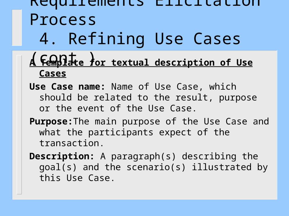
A Template for textual description of Use Cases
Use Case name: Name of Use Case, which should be related to the result, purpose or the event of the Use Case.
Purpose:The main purpose of the Use Case and what the participants expect of the transaction.
Description: A paragraph(s) describing the goal(s) and the scenario(s) illustrated by this Use Case.

Requirements Elicitation Process 4. Refining Use Cases (cont.)
A Template for textual description of Use Cases (cont.)
Actors: Who or what participates in the Use Case. That includes what individuals, organizations, job functions, software applications, software functions or machines collaborate in the Use Case.
Data Content: What data are in scope of this Use Case. What information is exchanged in the transactions that implement the Use Case.
Preconditions: What conditions are expected to exist prior to the start of the Use Case.
Begins When: What starts or triggers the performance of this Use Case.

Requirements Elicitation Process 4. Refining Use Cases (cont.)A Template for textual description of Use Cases (cont.)Ends When: When is the Use Case finished.Exceptions: What exceptional outcomes are there besides the
normal one expected for a successful performance of the Use Case.
Post Conditions: What is the state of "the system" after the Use Case has been completed
References: If this Use Case references other works or documents, or other Use Cases the references to these sources are placed here

Requirements Elicitation Process 4. Refining Use Cases (cont.) A simplified example of some sections: The Coffee MakerUC3: Flow of Events for the Delete Recipe Use Case
3.1 Preconditions: recipes exist in the system3.2 Main Flow: The user will be shown a list of all recipes in the system, and asked to choose the recipe, by number, that they wish to delete. [S1][E1][E2]3.3 Subflows:[S1] If the user selects an empty recipe to delete, the user is returned to the main menu.3.4 Alternative Flows:[E1] If the user selects a number that is out of bounds of the number of recipes, the user is returned to the main menu.[E2] If the user enters a alphabetic character, the user is returned to the main menu. .

The components of Use case description template

Requirements Elicitation Process
The process of requirements elicitation consists of the following steps
1. Identify Actors2. Identify Scenarios3. Identify Use Cases4. Refine Use Cases
5. Identify Relationships between actors and Use Cases
6. Identify Initial Analysis Objects7. Identify Non-functional requirements
Requirements Elicitation Process
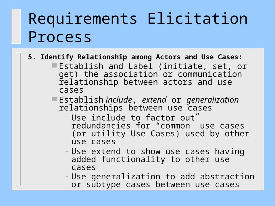
5. Identify Relationship among Actors and Use Cases: Establish and Label (initiate, set, or get) the
association or communication relationship between actors and use cases
Establish include, extend or generalization relationships between use cases
– Use include to factor out redundancies for “common” use cases (or utility Use Cases) used by other use cases
– Use extend to show use cases having added functionality to other use cases
– Use generalization to add abstraction or subtype cases between use cases

Label Associatons,e.g. Receive order, and accept payment,
Identify Multiplicity ofassociations

Requirements Elicitation Process
6. Identify Initial Analysis ObjectsThese can be nouns or processes in the textual requirements
(also called Domain objects)Types of objects may include:
– Interfaces to External Entities: Sensors, actuators, control panel, devices
– Information Items : Displays, Commands, etc.
– Entities which establishes the context of the system (to support Use case functionality): Controller, monitors, schedulers, handlers, servers, agents, wrappers
Requirements Elicitation Process
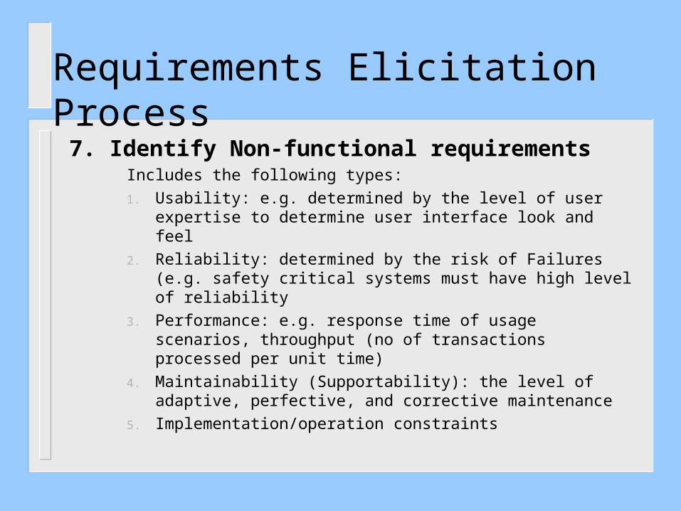
7. Identify Non-functional requirementsIncludes the following types:
1. Usability: e.g. determined by the level of user expertise to determine user interface look and feel
2. Reliability: determined by the risk of Failures (e.g. safety critical systems must have high level of reliability
3. Performance: e.g. response time of usage scenarios, throughput (no of transactions processed per unit time)
4. Maintainability (Supportability): the level of adaptive, perfective, and corrective maintenance
5. Implementation/operation constraints


