RF182C communication module ___________________ __________ _______________________________________________________________________________________________________________________________________________________________________________________________________ _____________________________________ ______________________________________________________SIMATIC Sensors RFID systems RF182C communication module Operating Instructions 10/2010 J31069-D0204-U001-A2-7618 Introduction 1 Description 2 Mounting 3 Connecting 4 Parameterizing 5 Communication interface 6 Maintenance and Service 7 Diagnostics 8 Error messages 9 Examples/applications 10 Technical data 11 Dimension drawings 12 Connecting cable to the reader/SLG 13 Ordering data 14 Command and acknowledgement telegrams A Addressing of the RFID tags B Transfer scheme for hexadecimal tag data via XML C Service & support D
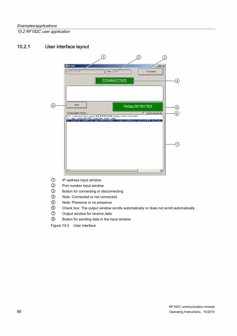
This manual contains notices you have to observe in order to ensure your personal safety, as well as to prevent damage to property. The notices referring to your personal safety are highlighted in the manual by a safety alert symbol, notices referring only to property damage have no safety alert symbol. These notices shown below are graded according to the degree of danger.
DANGER indicates that death or severe personal injury will result if proper precautions are not taken.
WARNING indicates that death or severe personal injury may result if proper precautions are not taken.
CAUTION with a safety alert symbol, indicates that minor personal injury can result if proper precautions are not taken.
CAUTION without a safety alert symbol, indicates that property damage can result if proper precautions are not taken.
NOTICE indicates that an unintended result or situation can occur if the corresponding information is not taken into account.
If more than one degree of danger is present, the warning notice representing the highest degree of danger will be used. A notice warning of injury to persons with a safety alert symbol may also include a warning relating to property damage.
Qualified Personnel The product/system described in this documentation may be operated only by personnel qualified for the specific task in accordance with the relevant documentation for the specific task, in particular its warning notices and safety instructions. Qualified personnel are those who, based on their training and experience, are capable of identifying risks and avoiding potential hazards when working with these products/systems.
Proper use of Siemens products Note the following:
WARNING Siemens products may only be used for the applications described in the catalog and in the relevant technical documentation. If products and components from other manufacturers are used, these must be recommended or approved by Siemens. Proper transport, storage, installation, assembly, commissioning, operation and maintenance are required to ensure that the products operate safely and without any problems. The permissible ambient conditions must be adhered to. The information in the relevant documentation must be observed.
Trademarks All names identified by ® are registered trademarks of the Siemens AG. The remaining trademarks in this publication may be trademarks whose use by third parties for their own purposes could violate the rights of the owner.
Disclaimer of Liability We have reviewed the contents of this publication to ensure consistency with the hardware and software described. Since variance cannot be precluded entirely, we cannot guarantee full consistency. However, the information in this publication is reviewed regularly and any necessary corrections are included in subsequent editions.
Siemens AG Industry Sector Postfach 48 48 90026 NÜRNBERG GERMANY
3.1 Mounting position, mounting dimensions.....................................................................................13 3.2 Mounting the I/O module..............................................................................................................14 3.3 Mounting the connection block ....................................................................................................16 3.4 Replacing labels...........................................................................................................................18 3.5 Disassembling the RF182C .........................................................................................................19
4 Connecting .............................................................................................................................................. 21 4.1 Wiring connection block M12, 7/8"...............................................................................................24 4.2 Wiring of the push-pull connection block .....................................................................................27 4.3 Loop-through of Ethernet and supply voltage..............................................................................30 4.4 Wiring an RF182C to a controller with Ethernet connection........................................................32 4.5 Connecting the RF182C to functional ground (PE) .....................................................................33
5 Parameterizing ........................................................................................................................................ 35 5.1 Address assignment for Ethernet.................................................................................................35 5.2 Data communication between client and RF182C.......................................................................37 5.3 Factory setting of the RF182C.....................................................................................................40 5.4 Assigning the IP address .............................................................................................................41 5.4.1 Overview ......................................................................................................................................41 5.4.2 Web server...................................................................................................................................41 5.4.3 Primary Setup Tool ......................................................................................................................45 5.5 Troubleshooting: Assigning the IP address .................................................................................48
6 Communication interface ......................................................................................................................... 49 6.1 Overview of commands ...............................................................................................................49 6.2 Configuration parameters of the RF182C....................................................................................50 6.3 Input parameters of the RF182C .................................................................................................52 6.4 Commands of the communication module ..................................................................................53 6.4.1 writeTagData................................................................................................................................53 6.4.2 readTagData ................................................................................................................................54 6.4.3 initializeTag ..................................................................................................................................55 6.4.4 getReaderStatus ..........................................................................................................................56 6.4.5 getTagStatus................................................................................................................................57 6.4.6 setAnt ...........................................................................................................................................58 6.4.7 heartbeat ......................................................................................................................................59
Table of contents
RF182C communication module 4 Operating Instructions, 10/2010
7 Maintenance and Service ........................................................................................................................ 63 7.1 Replacing the RF182C communication module.......................................................................... 63 7.2 Firmware update ......................................................................................................................... 65 7.3 Reader update ............................................................................................................................ 65
8 Diagnostics .............................................................................................................................................. 67 8.1 Diagnostics using LEDs .............................................................................................................. 67
9 Error messages ....................................................................................................................................... 71 9.1 Response without error entry...................................................................................................... 71 9.2 Response with error entry ........................................................................................................... 71 9.3 Error messages of the RF182C .................................................................................................. 72 9.4 Diagnostics via Web server......................................................................................................... 78 9.4.1 Saving/reading of I&M data records............................................................................................ 78 9.4.2 Communication status query....................................................................................................... 79 9.4.3 Event and message frame overview........................................................................................... 80
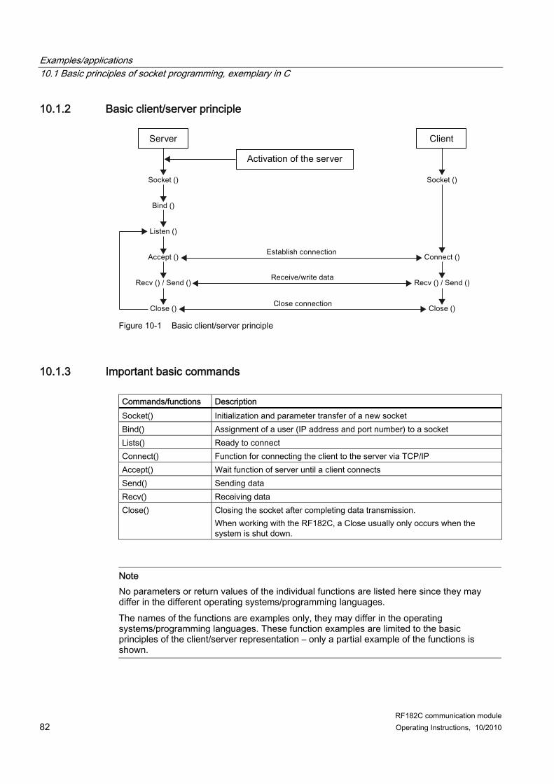
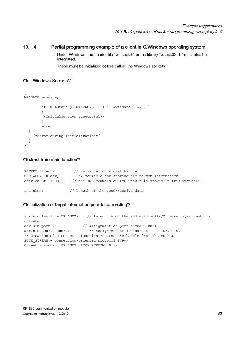
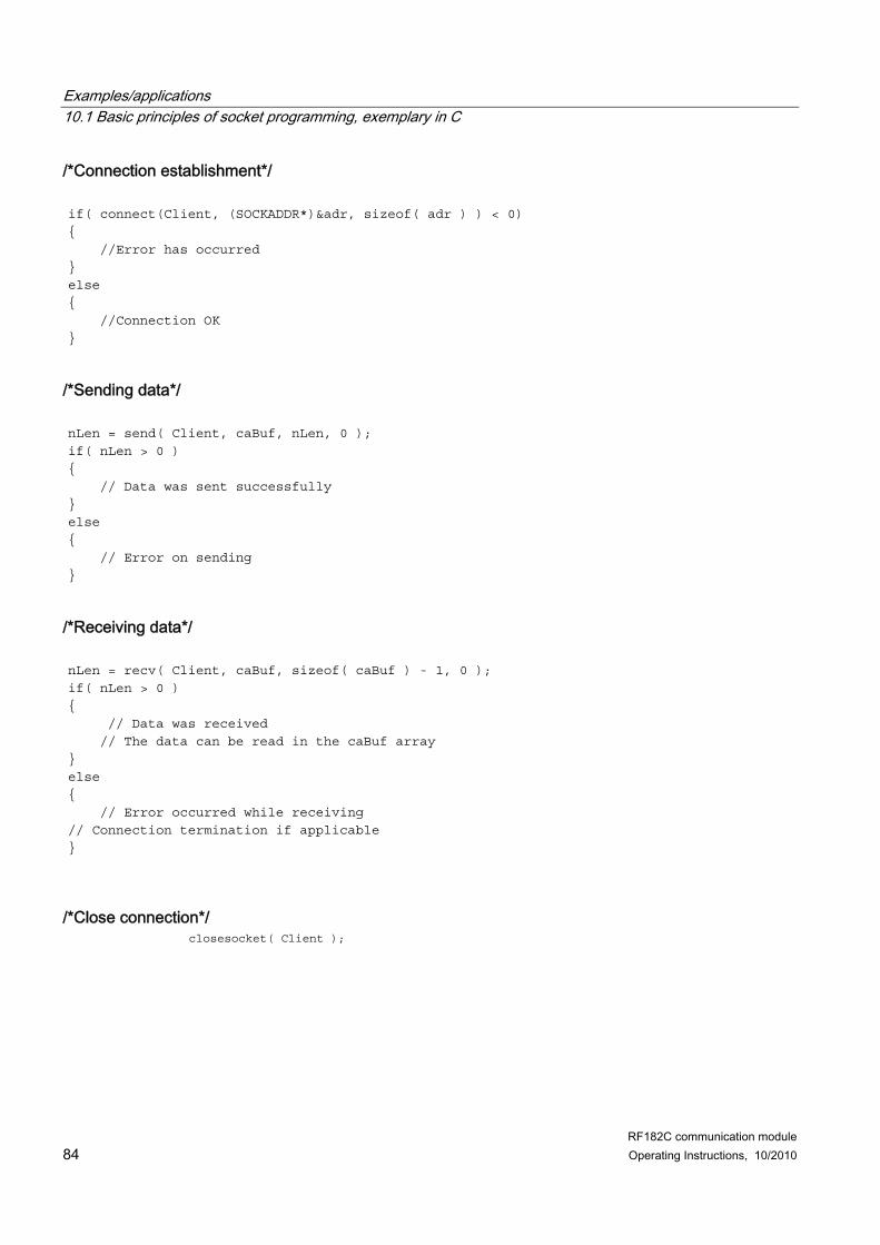
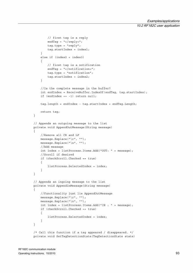
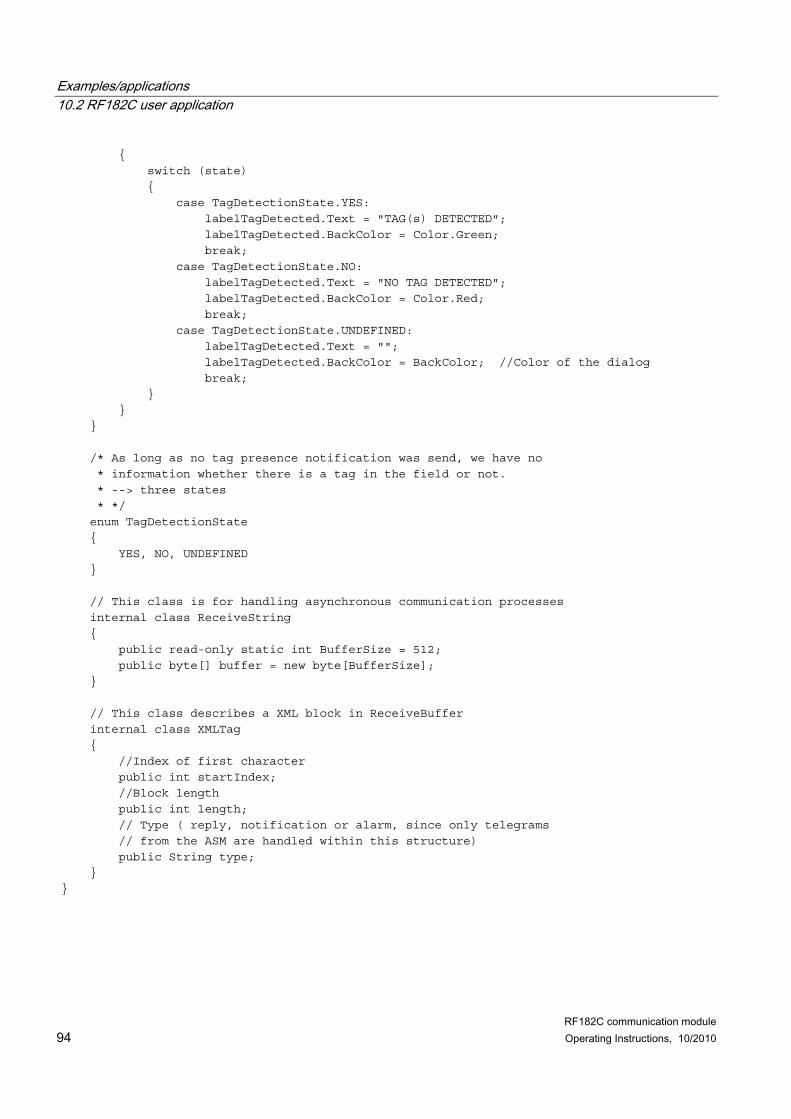
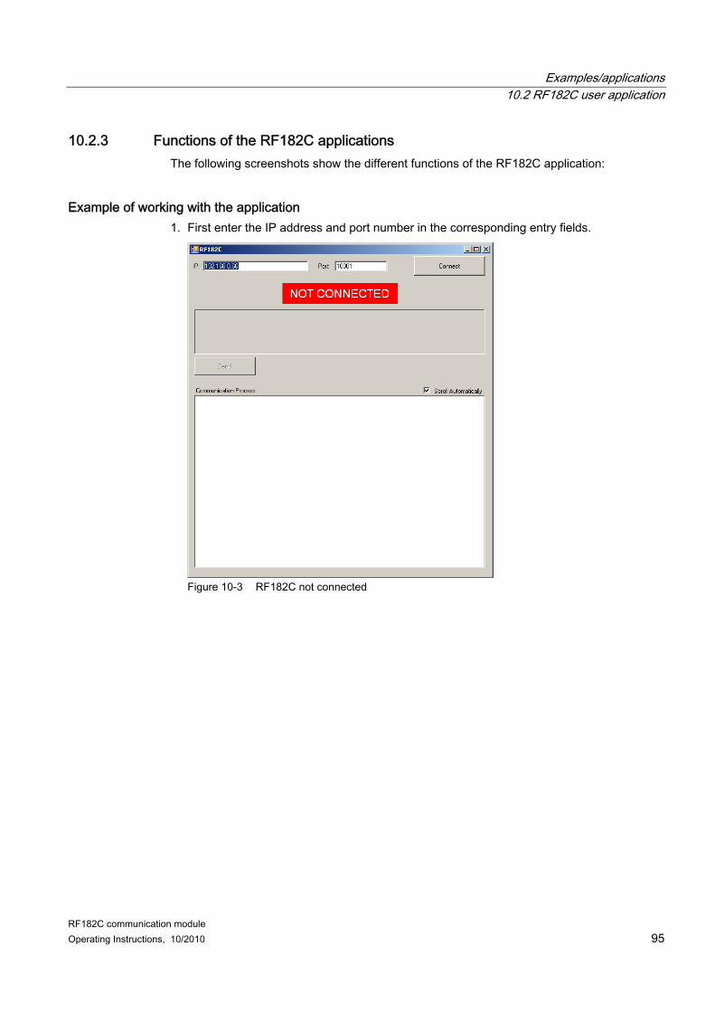
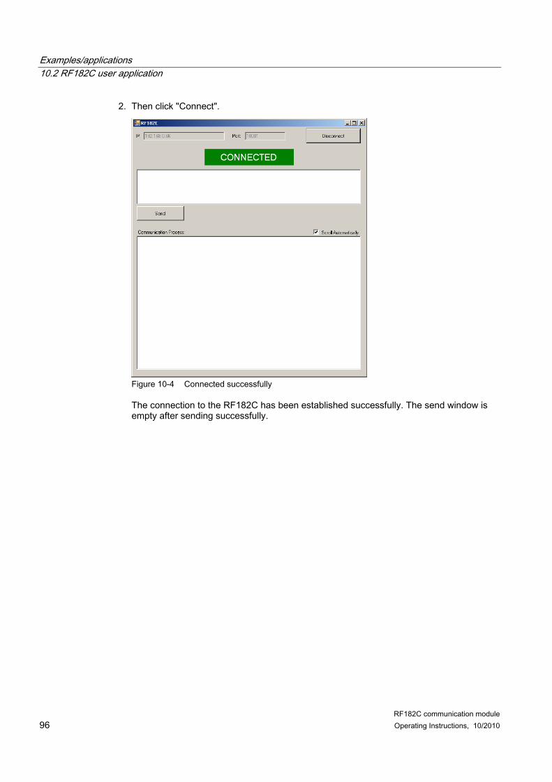
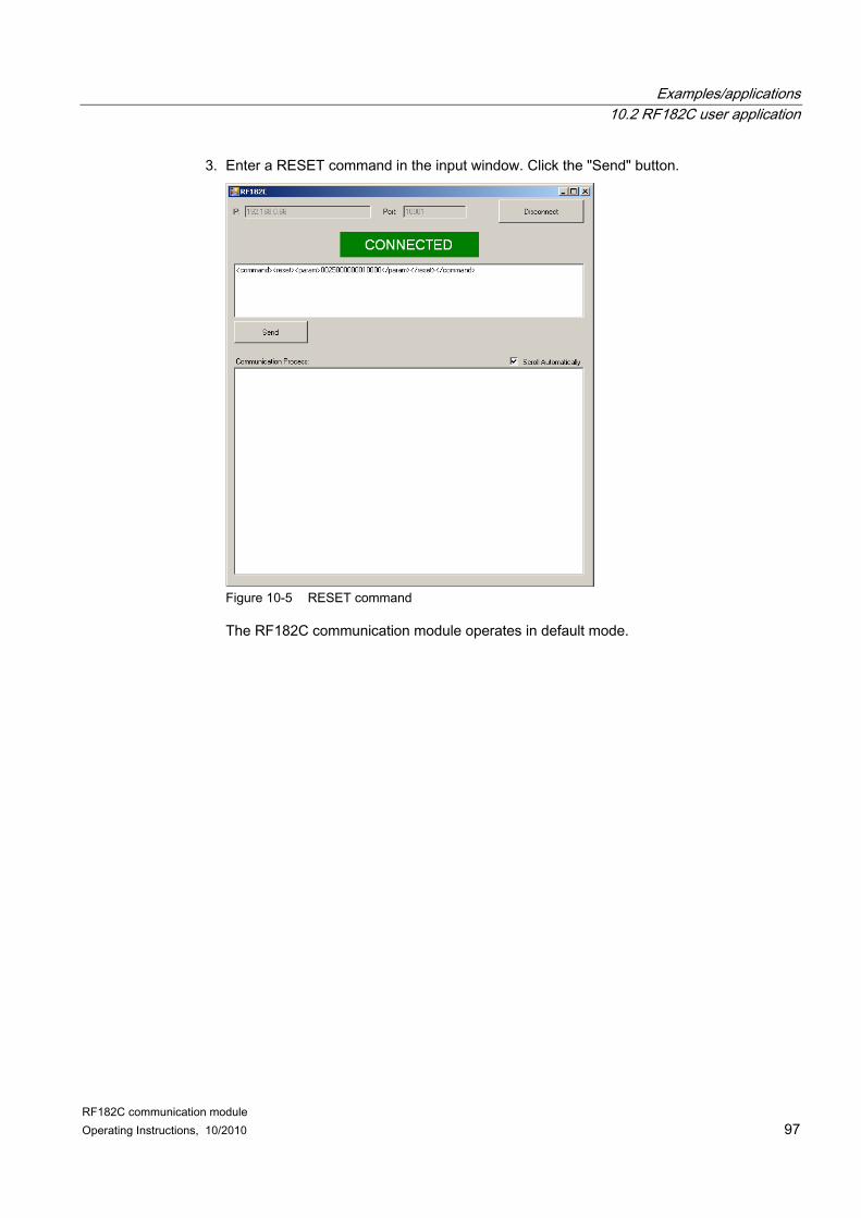
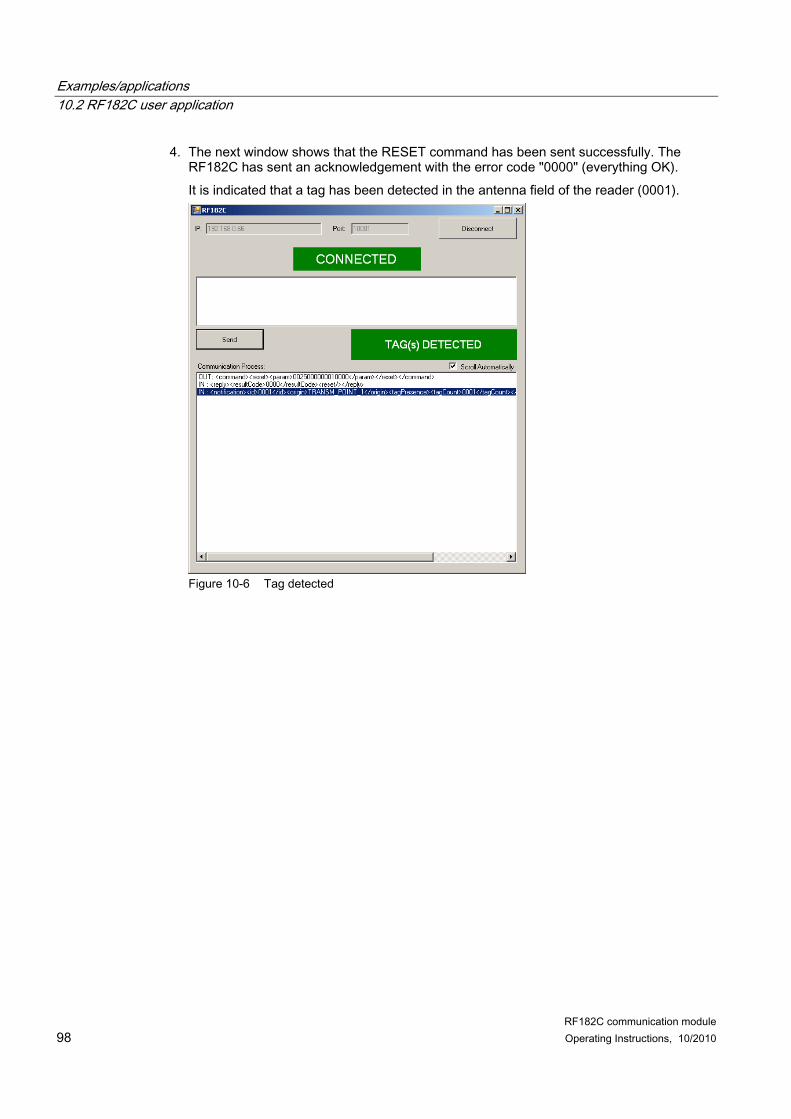
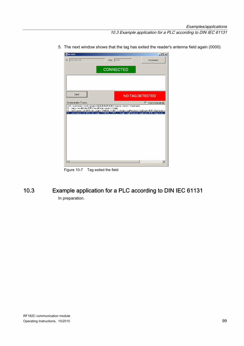
10 Examples/applications ............................................................................................................................. 81 10.1 Basic principles of socket programming, exemplary in C ........................................................... 81 10.1.1 Socket programming requirements............................................................................................. 81 10.1.2 Basic client/server principle......................................................................................................... 82 10.1.3 Important basic commands......................................................................................................... 82 10.1.4 Partial programming example of a client in C/Windows operating system................................. 83 10.2 RF182C user application............................................................................................................. 85 10.2.1 User interface layout ................................................................................................................... 86 10.2.2 Extracts example code of the user application in C#.................................................................. 87 10.2.3 Functions of the RF182C applications ........................................................................................ 95 10.3 Example application for a PLC according to DIN IEC 61131...................................................... 99
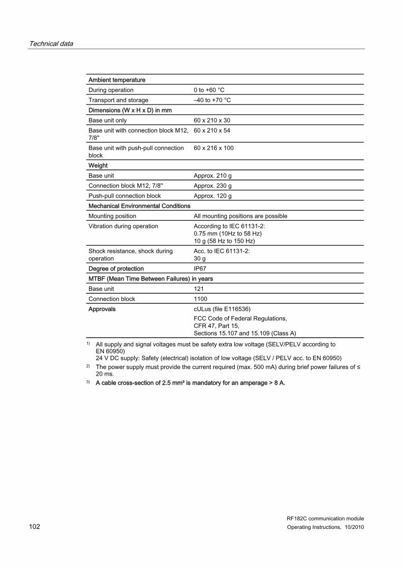
11 Technical data ....................................................................................................................................... 101 12 Dimension drawings .............................................................................................................................. 103
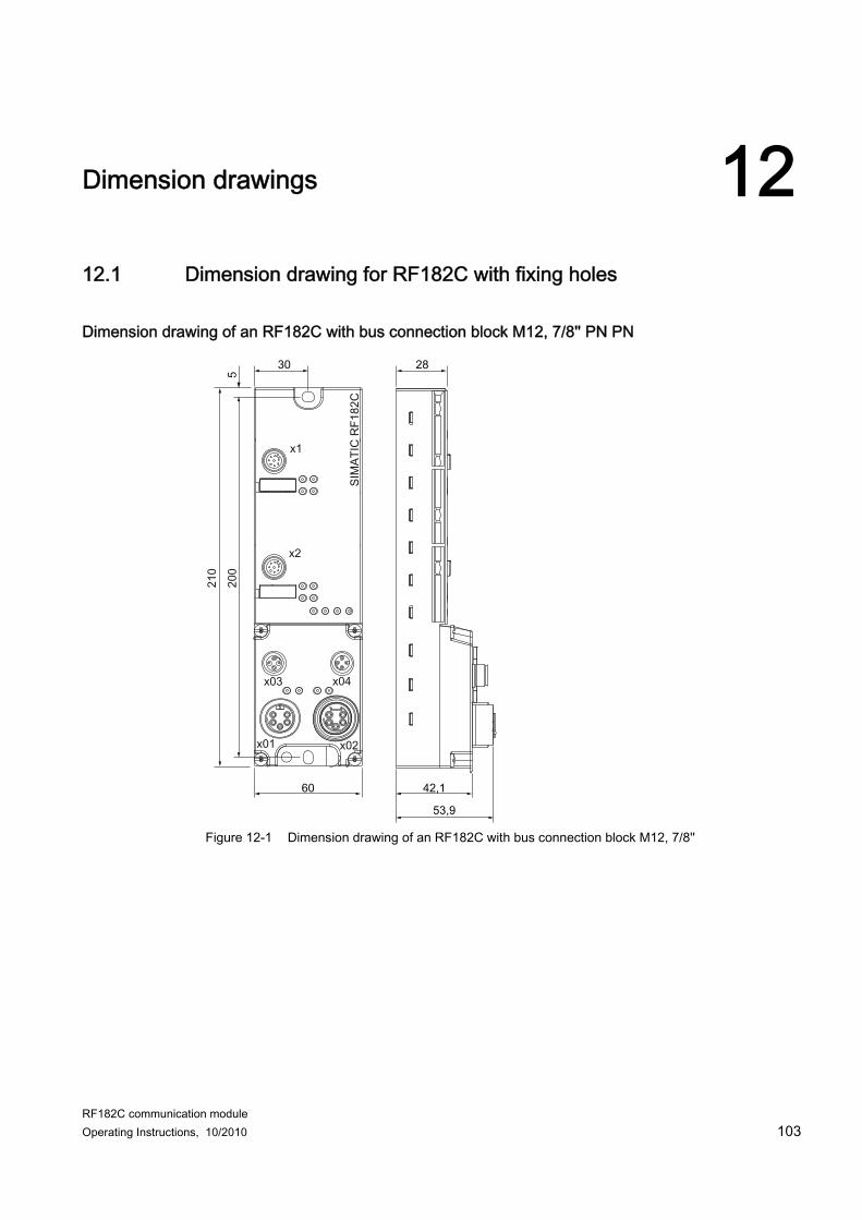
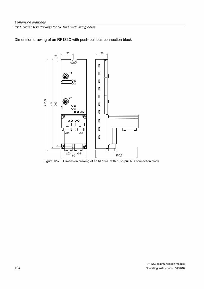
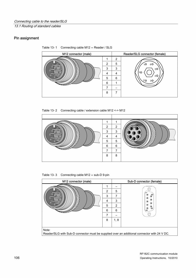
12.1 Dimension drawing for RF182C with fixing holes ..................................................................... 103 13 Connecting cable to the reader/SLG...................................................................................................... 105
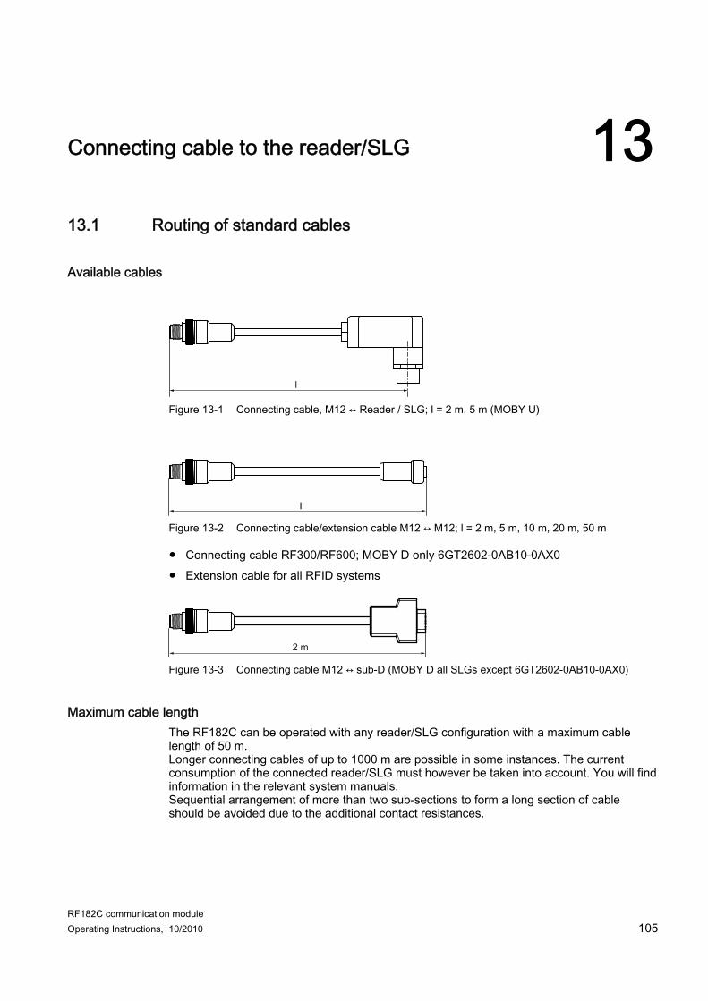
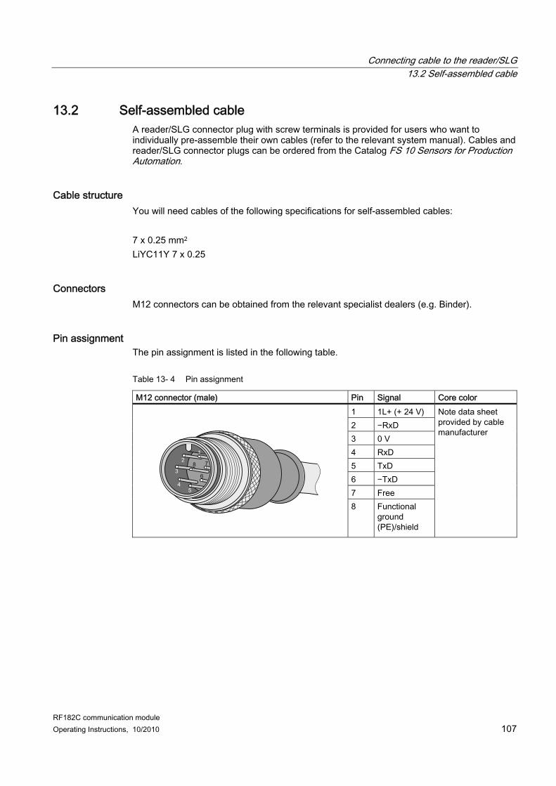
13.1 Routing of standard cables ....................................................................................................... 105 13.2 Self-assembled cable................................................................................................................ 107
14 Ordering data......................................................................................................................................... 109 A Command and acknowledgement telegrams......................................................................................... 111 B Addressing of the RFID tags.................................................................................................................. 123 C Transfer scheme for hexadecimal tag data via XML .............................................................................. 125 D Service & support .................................................................................................................................. 127
RF182C communication module Operating Instructions, 10/2010 5
Introduction 11.1 Introduction
Purpose of these operating instructions The information provided in these Operating Instructions enables you to operate the RF182C communication module on a standard PC or a PLC.
Basic knowledge required These operating instructions assume general knowledge of automation engineering and identification systems. You also require basic knowledge of socket programming (TCP/IP communication via Ethernet) Socket programming depends on the programming language or the operating system used (Windows, Linux, or Unix).
Scope of this manual The Operating Instructions apply to the RF182C communication module.
Position in the information landscape ● The manual of the relevant RFID family contains information on the readers/SLGs to be
connected. ● Special information on parameterizing the RF620R/RF630R readers in conjunction with
the RF182C communication module can be found in the "RF620R/RF630R parameterization manual".
Guide These Operating Instructions describe the hardware and the communications interface of the RF182C communication module. They comprise introductory sections and reference sections (e.g. technical data). The operating instructions include the following subject areas: ● Connection of the RF182C communication module ● Parameterization and programming of the RF182C communication module ● Diagnostics information ● Display elements of the RF182C communication module ● Information on repair and maintenance (e.g. firmware update) ● Technical data as well as dimension drawings of the RF182C communication module ● Ordering data
Introduction 1.1 Introduction
RF182C communication module 6 Operating Instructions, 10/2010
Recycling and disposal ● Due to its environmentally compatible equipment, the RF182C communication module
can be recycled. ● Contact a certified electronic-waste disposal company to recycle and dispose of your old
equipment in an environment-friendly manner.
RF182C communication module Operating Instructions, 10/2010 7
Description 2
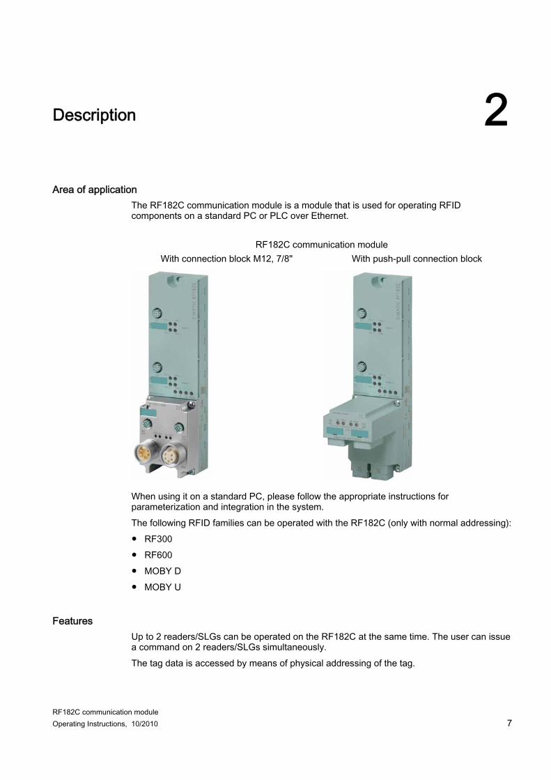
Area of application The RF182C communication module is a module that is used for operating RFID components on a standard PC or PLC over Ethernet.
RF182C communication module With connection block M12, 7/8" With push-pull connection block
When using it on a standard PC, please follow the appropriate instructions for parameterization and integration in the system. The following RFID families can be operated with the RF182C (only with normal addressing): ● RF300 ● RF600 ● MOBY D ● MOBY U
Features Up to 2 readers/SLGs can be operated on the RF182C at the same time. The user can issue a command on 2 readers/SLGs simultaneously. The tag data is accessed by means of physical addressing of the tag.
Description
RF182C communication module 8 Operating Instructions, 10/2010
Other features ● Degree of protection IP67 ● System integration with M12, 7/8" concept or with push-pull concept ● Standardized Ethernet interface ● Diagnostics support via web server ● Routing capability ● Firmware update via web server ● Support of identification and maintenance data sets (I&M): Mechanism for reading out
information via the communication module, and saving system information such as function, installation date, installation location, and comments
● Module supports SNMP
Layout The RF182C has the same enclosure as the RFID communication module ASM 456 for PROFIBUS and the RFID communication module RF180C for PROFINET. For connecting to Ethernet, the RF182C communication module features a connection block in one of the following designs: ● Connection block in M12 design, either with
RF182C communication module Operating Instructions, 10/2010 9
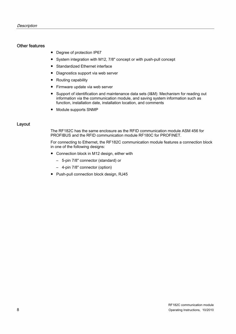
The following figure shows the basic design of the RF182C.
Figure 2-1 Basic design of the RF182C
Description
RF182C communication module 10 Operating Instructions, 10/2010
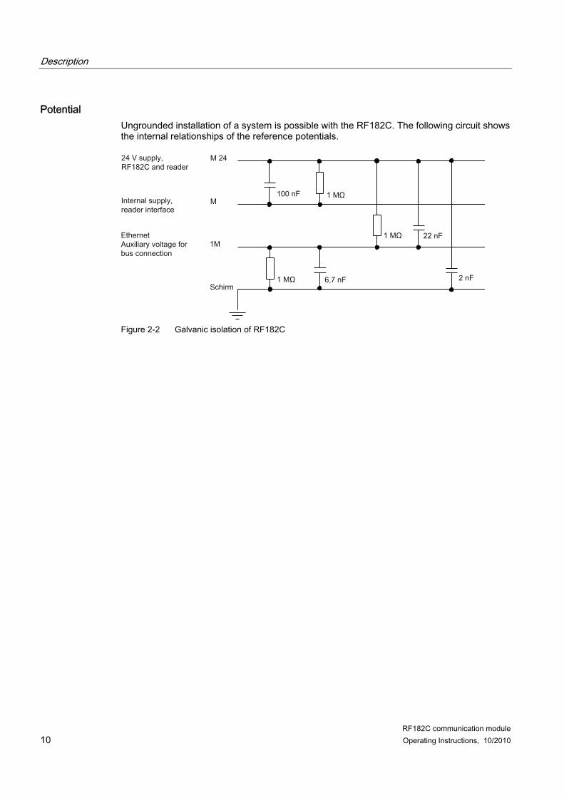
Potential Ungrounded installation of a system is possible with the RF182C. The following circuit shows the internal relationships of the reference potentials.
Figure 2-2 Galvanic isolation of RF182C
Description
RF182C communication module Operating Instructions, 10/2010 11
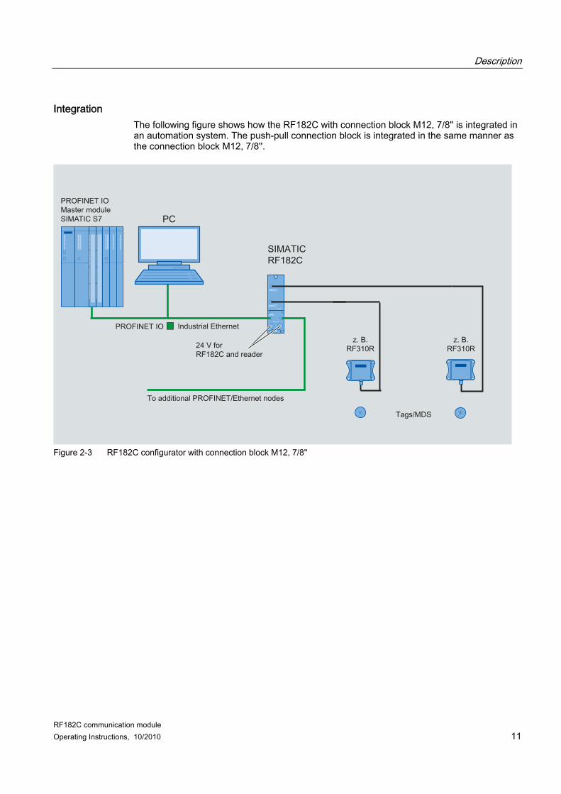
Integration The following figure shows how the RF182C with connection block M12, 7/8'' is integrated in an automation system. The push-pull connection block is integrated in the same manner as the connection block M12, 7/8''.
PROFINET IOMaster moduleSIMATIC S7
Figure 2-3 RF182C configurator with connection block M12, 7/8''�
Description
RF182C communication module 12 Operating Instructions, 10/2010
RF182C communication module Operating Instructions, 10/2010 13
Mounting 3
The RF182C communication module is designed for easy assembly.
3.1 Mounting position, mounting dimensions
Mounting position There are no restrictions regarding the mounting position for the RF182C.
Mounting dimensions and spacing
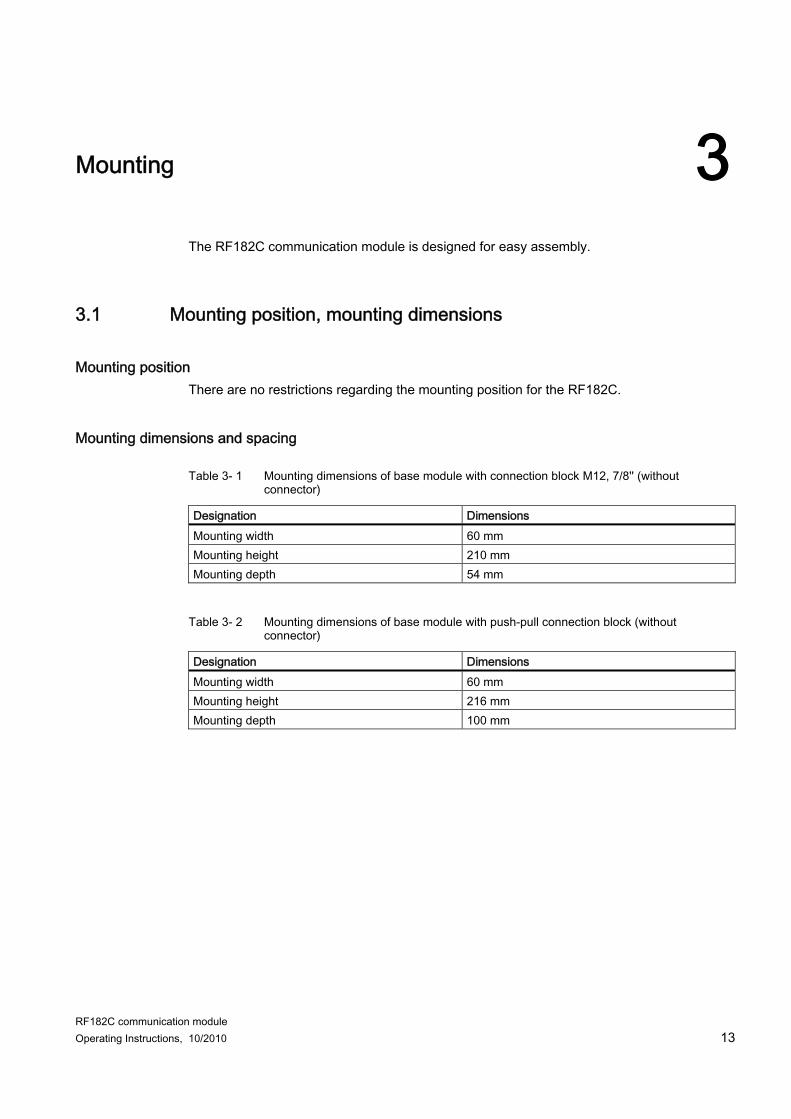
Table 3- 1 Mounting dimensions of base module with connection block M12, 7/8'' (without connector)
Designation Dimensions Mounting width 60 mm Mounting height 210 mm Mounting depth 54 mm
Table 3- 2 Mounting dimensions of base module with push-pull connection block (without connector)
Designation Dimensions Mounting width 60 mm Mounting height 216 mm Mounting depth 100 mm
Mounting 3.2 Mounting the I/O module
RF182C communication module 14 Operating Instructions, 10/2010
3.2 Mounting the I/O module
Features ● The base unit is mounted on a stable surface
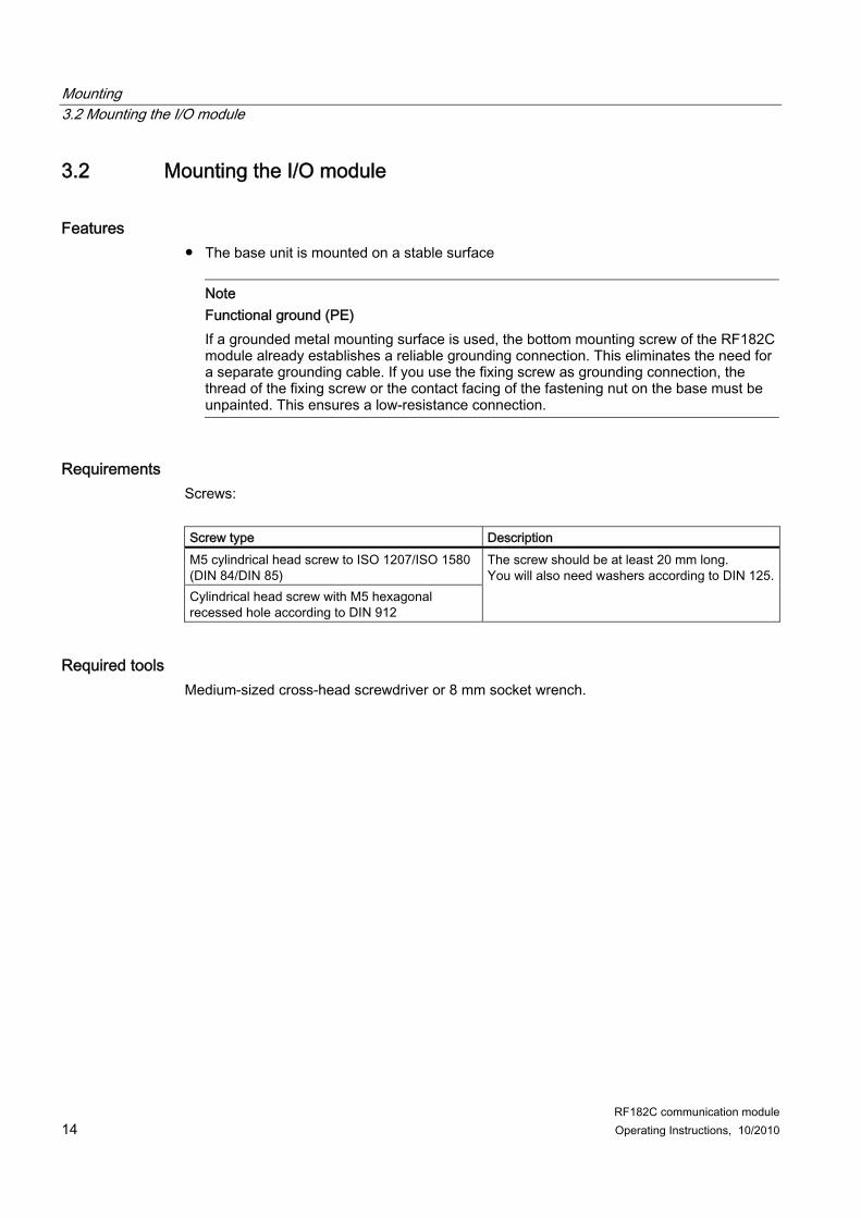
Note Functional ground (PE) If a grounded metal mounting surface is used, the bottom mounting screw of the RF182C module already establishes a reliable grounding connection. This eliminates the need for a separate grounding cable. If you use the fixing screw as grounding connection, the thread of the fixing screw or the contact facing of the fastening nut on the base must be unpainted. This ensures a low-resistance connection.
Requirements Screws: Screw type Description M5 cylindrical head screw to ISO 1207/ISO 1580 (DIN 84/DIN 85) Cylindrical head screw with M5 hexagonal recessed hole according to DIN 912
The screw should be at least 20 mm long. You will also need washers according to DIN 125.
Required tools Medium-sized cross-head screwdriver or 8 mm socket wrench.
Mounting 3.2 Mounting the I/O module
RF182C communication module Operating Instructions, 10/2010 15
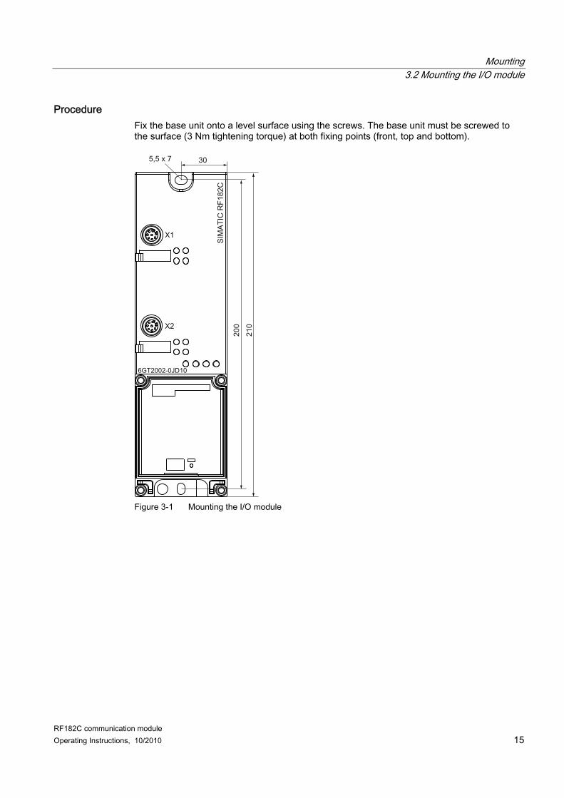
Procedure Fix the base unit onto a level surface using the screws. The base unit must be screwed to the surface (3 Nm tightening torque) at both fixing points (front, top and bottom).
Figure 3-1 Mounting the I/O module
Mounting 3.3 Mounting the connection block
RF182C communication module 16 Operating Instructions, 10/2010
3.3 Mounting the connection block
Features The connection block connects the RF182C with the Ethernet and supplies the base unit with voltage.
Requirements The base unit is already mounted
Required tools Cross-head screwdriver, medium.
Mounting the connection block 1. Plug the connection block into the base unit
Mounting 3.3 Mounting the connection block
RF182C communication module Operating Instructions, 10/2010 17
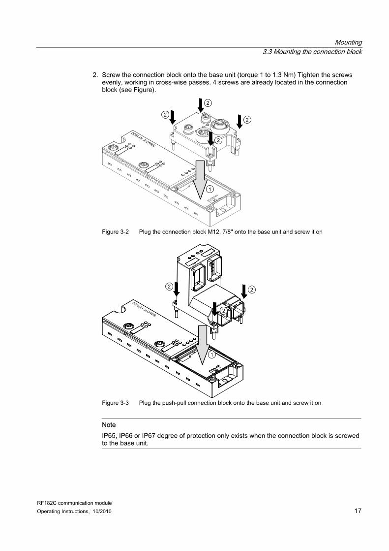
2. Screw the connection block onto the base unit (torque 1 to 1.3 Nm) Tighten the screws evenly, working in cross-wise passes. 4 screws are already located in the connection block (see Figure).
1
Figure 3-2 Plug the connection block M12, 7/8'' onto the base unit and screw it on
Figure 3-3 Plug the push-pull connection block onto the base unit and screw it on
Note IP65, IP66 or IP67 degree of protection only exists when the connection block is screwed to the base unit.
Mounting 3.4 Replacing labels
RF182C communication module 18 Operating Instructions, 10/2010
3.4 Replacing labels
Features You can use the labels to mark every channel on the base unit and the connection block. The labeling strips are supplied with clipped on label. ● 2 labels on the base module ● 1 label on connection block M12, 7/8'' ● 2 labels on push-pull connection block
Requirements If you want to replace the labels, you can reorder them. You will find the order number in section Ordering data (Page 109).
Required tools Screwdriver, size 2.5 mm to 4 mm.
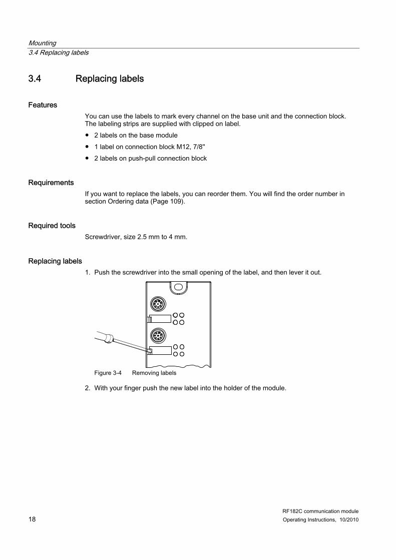
Replacing labels 1. Push the screwdriver into the small opening of the label, and then lever it out.
Figure 3-4 Removing labels
2. With your finger push the new label into the holder of the module.
Mounting 3.5 Disassembling the RF182C
RF182C communication module Operating Instructions, 10/2010 19
3.5 Disassembling the RF182C
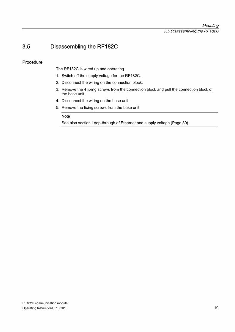
Procedure The RF182C is wired up and operating. 1. Switch off the supply voltage for the RF182C. 2. Disconnect the wiring on the connection block. 3. Remove the 4 fixing screws from the connection block and pull the connection block off
the base unit. 4. Disconnect the wiring on the base unit. 5. Remove the fixing screws from the base unit.
Note See also section Loop-through of Ethernet and supply voltage (Page 30).
Mounting 3.5 Disassembling the RF182C
RF182C communication module 20 Operating Instructions, 10/2010
RF182C communication module Operating Instructions, 10/2010 21
Connecting 4
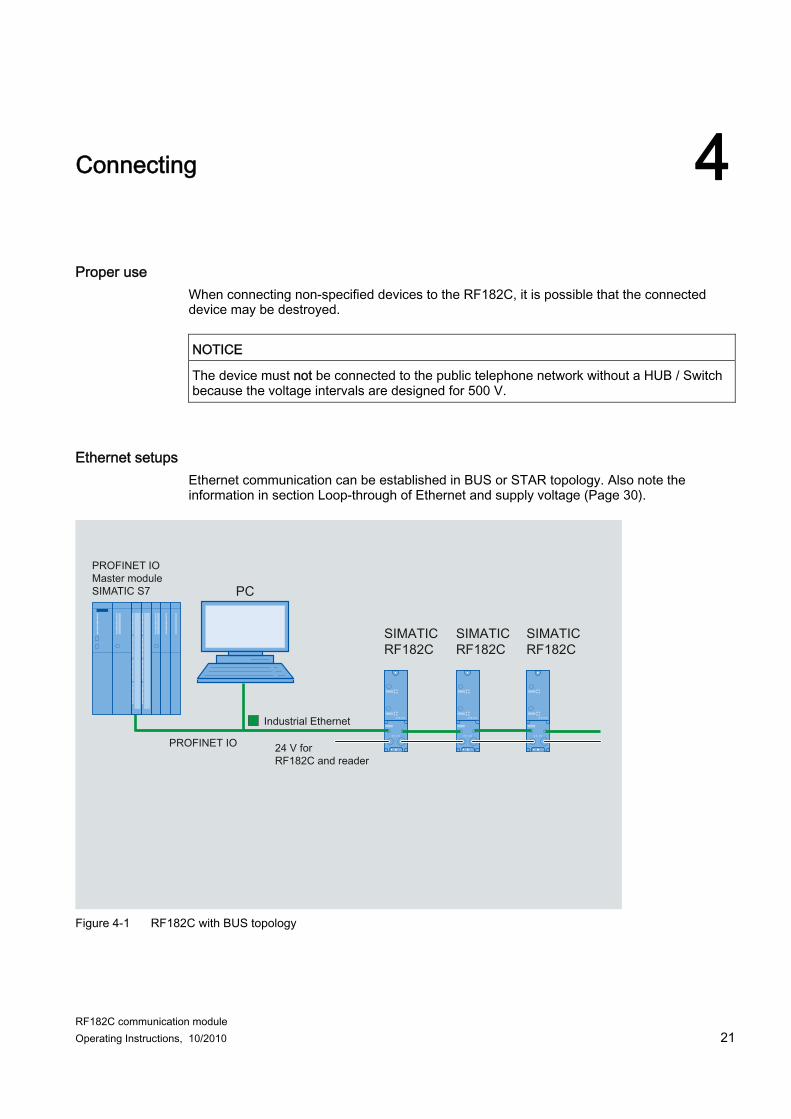
Proper use When connecting non-specified devices to the RF182C, it is possible that the connected device may be destroyed.
NOTICE The device must not be connected to the public telephone network without a HUB / Switch because the voltage intervals are designed for 500 V.
Ethernet setups Ethernet communication can be established in BUS or STAR topology. Also note the information in section Loop-through of Ethernet and supply voltage (Page 30).
PROFINET IOMaster moduleSIMATIC S7
Figure 4-1 RF182C with BUS topology
Connecting
RF182C communication module 22 Operating Instructions, 10/2010
PROFINET IOMaster moduleSIMATIC S7
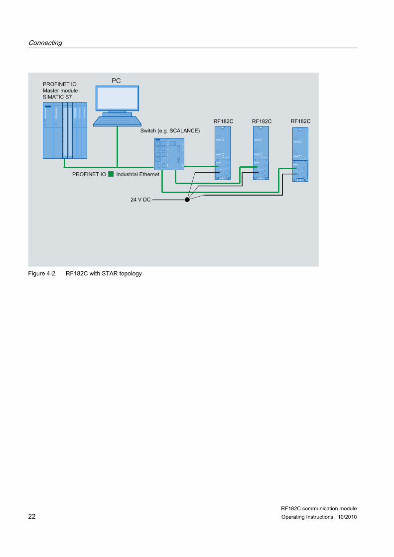
Figure 4-2 RF182C with STAR topology
Connecting
RF182C communication module Operating Instructions, 10/2010 23
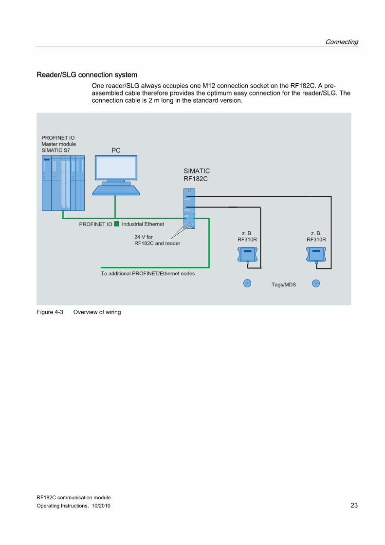
Reader/SLG connection system One reader/SLG always occupies one M12 connection socket on the RF182C. A pre-assembled cable therefore provides the optimum easy connection for the reader/SLG. The connection cable is 2 m long in the standard version.
PROFINET IOMaster moduleSIMATIC S7
Figure 4-3 Overview of wiring
Connecting 4.1 Wiring connection block M12, 7/8"
RF182C communication module 24 Operating Instructions, 10/2010
4.1 Wiring connection block M12, 7/8"
Features ● Connect the supply voltages and Ethernet to the connection block M12, 7/8":
– M12 connection in D coding: Ethernet – 7/8" connection: Supply voltages
● You can loop the supply voltages and Ethernet through via the second M12 or 7/8" circular socket connectors.
Requirements ● Wire connection block M12, 7/8" when the supply voltage is switched off.
Required tools Stripping tool, screwdriver for wiring the M12 and/or 7/8" connector if you are not using a pre-assembled cable.
Accessories required ● Pre-assembled cable with connector ● If you are not using a pre-assembled cable:
– M12: 4-core Ethernet cable (Twisted Pair), shielded and M12 connector, 4-pole, D coding (see Table Pin assignment of M12 connector, 4-pole, D coding (Ethernet))
– 7/8": 5-core cable and 7/8" connector (see Table Pin assignment for 7/8" connector (supply voltages))
● For order numbers, refer to Section Ordering data.
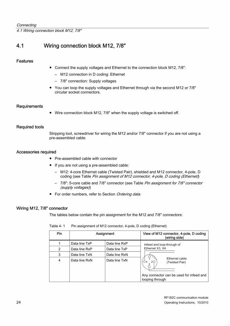
Wiring M12, 7/8" connector The tables below contain the pin assignment for the M12 and 7/8" connectors:
Table 4- 1 Pin assignment of M12 connector, 4-pole, D coding (Ethernet)
Pin Assignment View of M12 connector, 4-pole, D coding (wiring side)
1 Data line TxP Data line RxP 2 Data line RxP Data line TxP 3 Data line TxN Data line RxN 4 Data line RxN Data line TxN
Any connector can be used for infeed and looping through
Connecting 4.1 Wiring connection block M12, 7/8"
RF182C communication module Operating Instructions, 10/2010 25
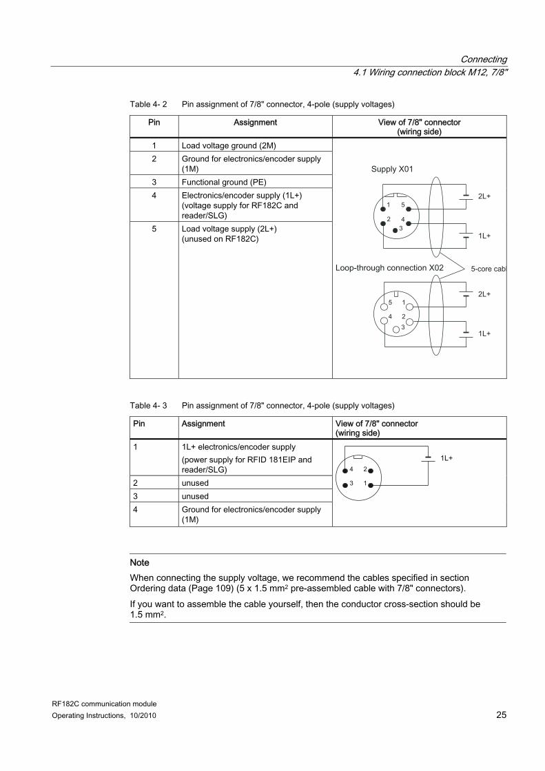
Pin Assignment View of 7/8" connector (wiring side)
1 1L+ electronics/encoder supply (power supply for RFID 181EIP and reader/SLG)
2 unused 3 unused 4 Ground for electronics/encoder supply
(1M)
Note When connecting the supply voltage, we recommend the cables specified in section Ordering data (Page 109) (5 x 1.5 mm2 pre-assembled cable with 7/8" connectors). If you want to assemble the cable yourself, then the conductor cross-section should be 1.5 mm2.
Connecting 4.1 Wiring connection block M12, 7/8"
RF182C communication module 26 Operating Instructions, 10/2010
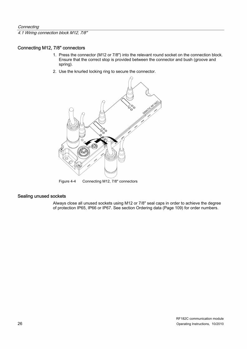
Connecting M12, 7/8" connectors 1. Press the connector (M12 or 7/8") into the relevant round socket on the connection block.
Ensure that the correct stop is provided between the connector and bush (groove and spring).
2. Use the knurled locking ring to secure the connector.
Figure 4-4 Connecting M12, 7/8" connectors
Sealing unused sockets Always close all unused sockets using M12 or 7/8" seal caps in order to achieve the degree of protection IP65, IP66 or IP67. See section Ordering data (Page 109) for order numbers.
Connecting 4.2 Wiring of the push-pull connection block
RF182C communication module Operating Instructions, 10/2010 27
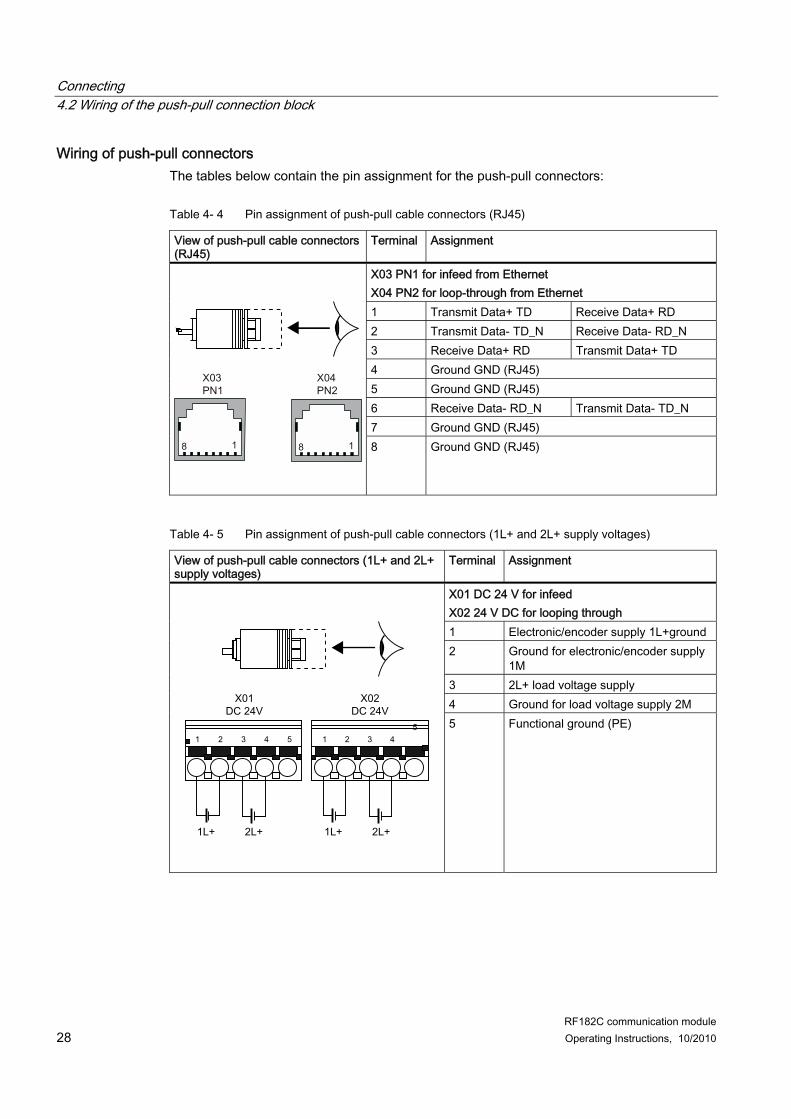
4.2 Wiring of the push-pull connection block
Features ● Connect the power supplies and Ethernet to the push-pull connection block:
Table 4- 5 Pin assignment of push-pull cable connectors (1L+ and 2L+ supply voltages)
View of push-pull cable connectors (1L+ and 2L+ supply voltages)
Terminal Assignment
X01 DC 24 V for infeed X02 24 V DC for looping through 1 Electronic/encoder supply 1L+ground 2 Ground for electronic/encoder supply
1M 3 2L+ load voltage supply 4 Ground for load voltage supply 2M
5 Functional ground (PE)
Connecting 4.2 Wiring of the push-pull connection block
RF182C communication module Operating Instructions, 10/2010 29
Note When connecting the power supply, we recommend the cables specified in section Ordering data (Page 109) (5 x 1.5 mm2 pre-assembled with push-pull connectors). If you want to assemble the cable yourself, then the conductor cross-section should be 1.5 mm2. A cable cross-section of 2.5 mm² is mandatory for an amperage > 8 A.
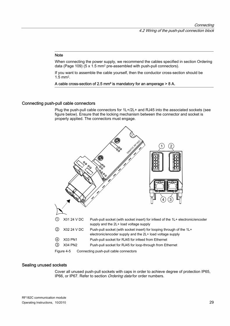
Connecting push-pull cable connectors Plug the push-pull cable connectors for 1L+/2L+ and RJ45 into the associated sockets (see figure below). Ensure that the locking mechanism between the connector and socket is properly applied. The connectors must engage.
① X01 24 V DC Push-pull socket (with socket insert) for infeed of the 1L+ electronic/encoder
supply and the 2L+ load voltage supply ② X02 24 V DC Push-pull socket (with socket insert) for looping through of the 1L+
electronic/encoder supply and the 2L+ load voltage supply ④ X03 PN1 Push-pull socket for RJ45 for infeed from Ethernet ③ X04 PN2 Push-pull socket for RJ45 for loop-through from Ethernet Figure 4-5 Connecting push-pull cable connectors
Sealing unused sockets Cover all unused push-pull sockets with caps in order to achieve degree of protection IP65, IP66, or IP67. Refer to section Ordering data for order numbers.
Connecting 4.3 Loop-through of Ethernet and supply voltage
RF182C communication module 30 Operating Instructions, 10/2010
4.3 Loop-through of Ethernet and supply voltage
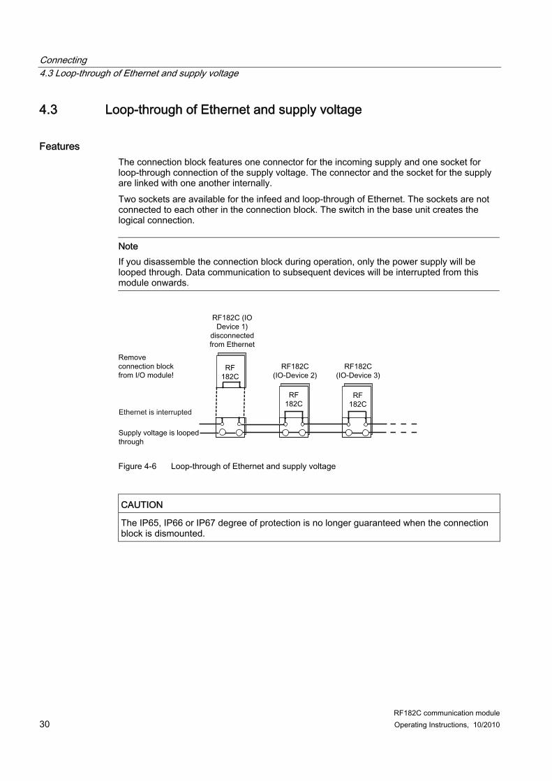
Features The connection block features one connector for the incoming supply and one socket for loop-through connection of the supply voltage. The connector and the socket for the supply are linked with one another internally. Two sockets are available for the infeed and loop-through of Ethernet. The sockets are not connected to each other in the connection block. The switch in the base unit creates the logical connection.
Note If you disassemble the connection block during operation, only the power supply will be looped through. Data communication to subsequent devices will be interrupted from this module onwards.
Figure 4-6 Loop-through of Ethernet and supply voltage
CAUTION The IP65, IP66 or IP67 degree of protection is no longer guaranteed when the connection block is dismounted.
Connecting 4.3 Loop-through of Ethernet and supply voltage
RF182C communication module Operating Instructions, 10/2010 31
Notes for wiring ● If you are wiring your structure, then you must take into account the impact of cable
length on supply voltage to the RF182C. Example: When using a 10 m long cable with a diameter of 1.5 mm2, the voltage drop is 2.5 V with a loading of 10 A. This corresponds to 0.25 V at a 1 A load.
● The maximum infeed current for connection block M12, 7/8" is 6 A at 1L+ and 8 A at 2L+. These values must not be exceeded.
● The maximum infeed current of the push-pull connection block is 12 A for 1L+ and 2L+ at up to 40 °C and 8 A for 1L+ and 2L+ at up to 60 °C. These values must not be exceeded.
● Adhere to the current carrying capacity of the connected cables, which depends on the conductor material, the conductor cross-section and the ambient temperature.
CAUTION
If you do not observe the maximum infeed current and the cable cross-section required, this may result in the cable isolation and contacts overheating and to the device being damaged.
CAUTION
Damage A cable cross-section of 2.5 mm² is mandatory for an amperage > 8 A!
Connecting 4.4 Wiring an RF182C to a controller with Ethernet connection
RF182C communication module 32 Operating Instructions, 10/2010
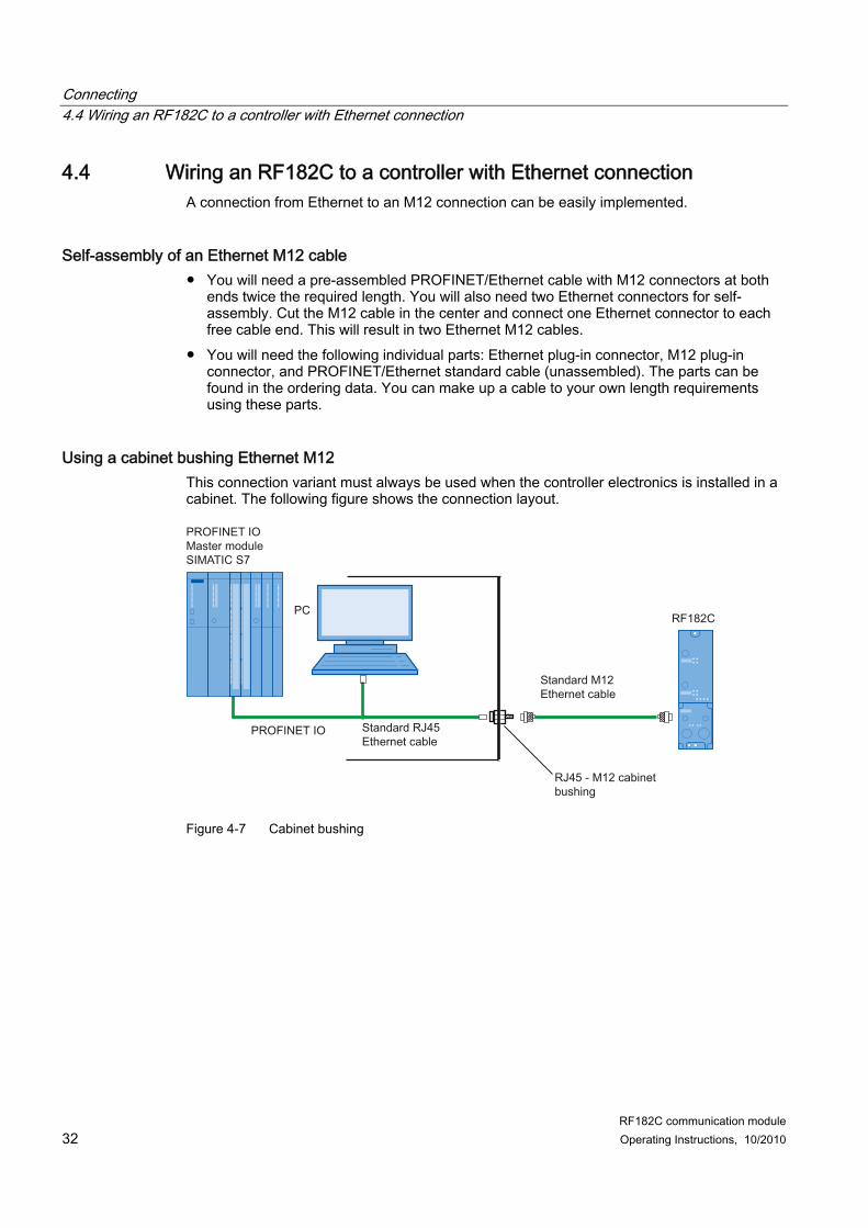
4.4 Wiring an RF182C to a controller with Ethernet connection A connection from Ethernet to an M12 connection can be easily implemented.
Self-assembly of an Ethernet M12 cable ● You will need a pre-assembled PROFINET/Ethernet cable with M12 connectors at both
ends twice the required length. You will also need two Ethernet connectors for self-assembly. Cut the M12 cable in the center and connect one Ethernet connector to each free cable end. This will result in two Ethernet M12 cables.
● You will need the following individual parts: Ethernet plug-in connector, M12 plug-in connector, and PROFINET/Ethernet standard cable (unassembled). The parts can be found in the ordering data. You can make up a cable to your own length requirements using these parts.
Using a cabinet bushing Ethernet M12 This connection variant must always be used when the controller electronics is installed in a cabinet. The following figure shows the connection layout.
PROFINET IOMaster moduleSIMATIC S7
Figure 4-7 Cabinet bushing
Connecting 4.5 Connecting the RF182C to functional ground (PE)
RF182C communication module Operating Instructions, 10/2010 33
4.5 Connecting the RF182C to functional ground (PE)
Features ● You have to connect the RF182C to the functional ground (PE). For this purpose, a
grounding screw for one grounding cable is provided on the communication module. ● If a grounded metal mounting surface is used, the bottom mounting screw of the RF182C
module already establishes a reliable grounding connection. This eliminates the need for a separate grounding cable.
● The connection to functional ground (PE) is also required to deflect the interference currents and for electromagnetic compatibility.
Requirements ● Always make sure there is a low-resistance connection to the functional ground (PE). ● If you use the fixing screw as grounding connection, the thread of the fixing screw or the
contact facing of the fastening nut on the base must be unpainted. This ensures a low-resistance connection.
Required tools (only if grounding via the grounding cable is required). ● Screwdriver ● Stripping tool ● Crimp tool
Required accessories (only if grounding via the grounding cable is required). ● M5 x 10 grounding screw and washers ● Grounding cable (copper braided cable) with minimum cross-section of 4 mm2 ● Cable lug
Connecting 4.5 Connecting the RF182C to functional ground (PE)
RF182C communication module 34 Operating Instructions, 10/2010
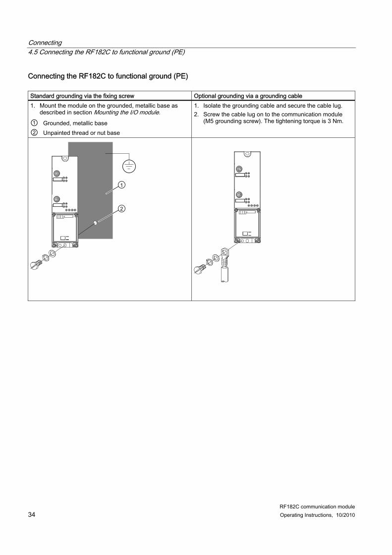
Connecting the RF182C to functional ground (PE) Standard grounding via the fixing screw Optional grounding via a grounding cable 1. Mount the module on the grounded, metallic base as
described in section Mounting the I/O module. ① Grounded, metallic base ② Unpainted thread or nut base
1. Isolate the grounding cable and secure the cable lug. 2. Screw the cable lug on to the communication module
(M5 grounding screw). The tightening torque is 3 Nm.
RF182C communication module Operating Instructions, 10/2010 35
Parameterizing 55.1 Address assignment for Ethernet
The reader is connected to Ethernet via the RF182C communication module. Communication between the application in the PC (client) and the reader (via the RF182C as server) only functions with a unique address assignment:
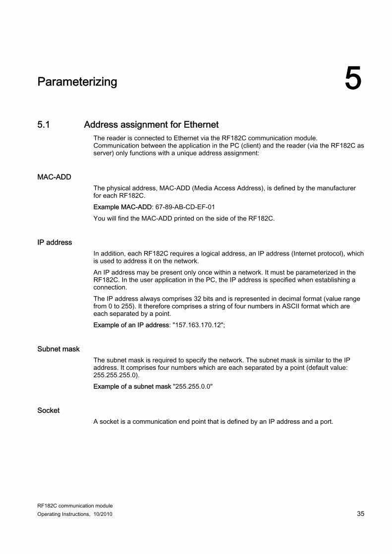
MAC-ADD The physical address, MAC-ADD (Media Access Address), is defined by the manufacturer for each RF182C. Example MAC-ADD: 67-89-AB-CD-EF-01 You will find the MAC-ADD printed on the side of the RF182C.
IP address In addition, each RF182C requires a logical address, an IP address (Internet protocol), which is used to address it on the network. An IP address may be present only once within a network. It must be parameterized in the RF182C. In the user application in the PC, the IP address is specified when establishing a connection. The IP address always comprises 32 bits and is represented in decimal format (value range from 0 to 255). It therefore comprises a string of four numbers in ASCII format which are each separated by a point. Example of an IP address: "157.163.170.12";
Subnet mask The subnet mask is required to specify the network. The subnet mask is similar to the IP address. It comprises four numbers which are each separated by a point (default value: 255.255.255.0). Example of a subnet mask "255.255.0.0"
Socket A socket is a communication end point that is defined by an IP address and a port.
Parameterizing 5.1 Address assignment for Ethernet
RF182C communication module 36 Operating Instructions, 10/2010
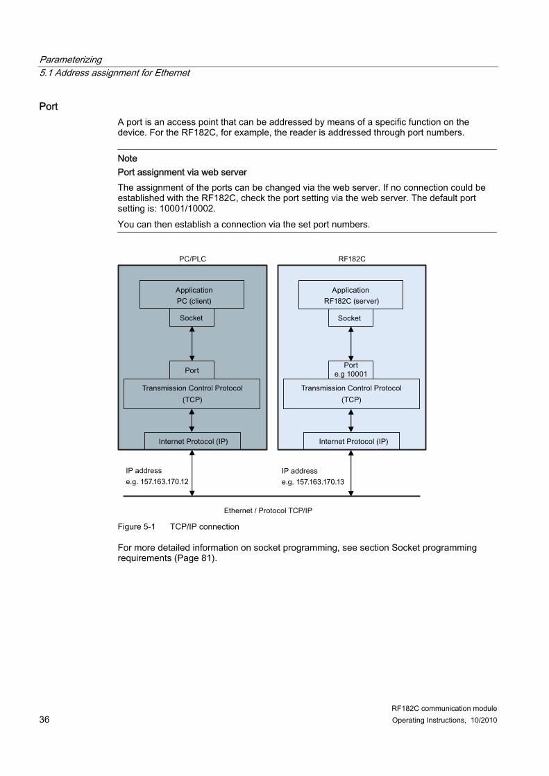
Port A port is an access point that can be addressed by means of a specific function on the device. For the RF182C, for example, the reader is addressed through port numbers.
Note Port assignment via web server The assignment of the ports can be changed via the web server. If no connection could be established with the RF182C, check the port setting via the web server. The default port setting is: 10001/10002. You can then establish a connection via the set port numbers.
Figure 5-1 TCP/IP connection
For more detailed information on socket programming, see section Socket programming requirements (Page 81).
Parameterizing 5.2 Data communication between client and RF182C
RF182C communication module Operating Instructions, 10/2010 37
5.2 Data communication between client and RF182C
Basic sequence ● The module has run up and has not been parameterized yet.
Note Connection problems? If no connection could be established with the RF182C, check the the communication settings (IP address, port number) of the communication module via the web server (Page 41).
● Optionally, a configuration message frame (comDevSetConfig) can be sent to the RF182C to change the communication mode stored in the RF182C by default. The client that configures the RF182C first also defines the RF182C settings. Further configurations during operation are not possible. The module must be de-energized or restarted by means of a "Reset" via the web server so that it can be reconfigured.
Parameterizing 5.2 Data communication between client and RF182C
RF182C communication module 38 Operating Instructions, 10/2010
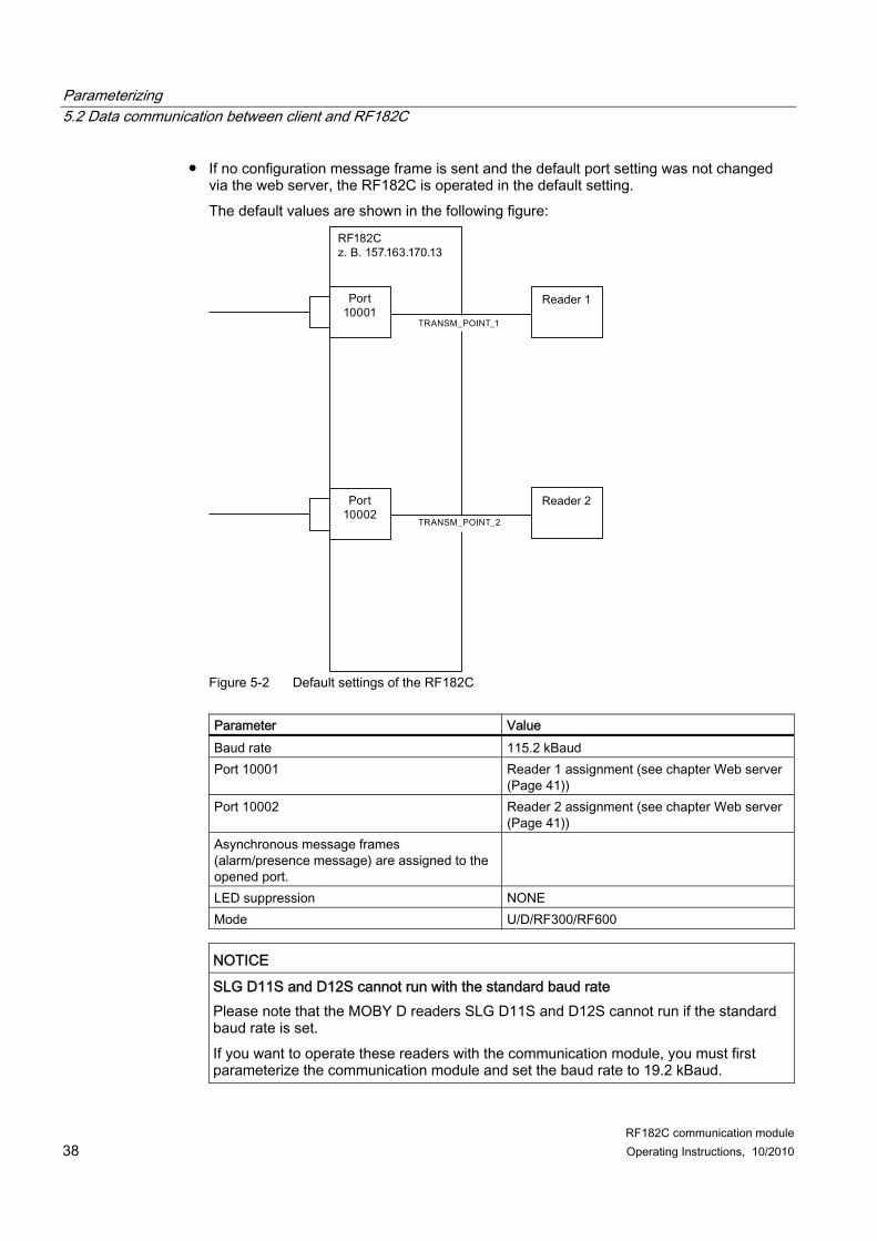
● If no configuration message frame is sent and the default port setting was not changed via the web server, the RF182C is operated in the default setting. The default values are shown in the following figure:
Figure 5-2 Default settings of the RF182C
Parameter Value Baud rate 115.2 kBaud Port 10001 Reader 1 assignment (see chapter Web server
(Page 41)) Port 10002 Reader 2 assignment (see chapter Web server
(Page 41)) Asynchronous message frames (alarm/presence message) are assigned to the opened port.
LED suppression NONE Mode U/D/RF300/RF600
NOTICE
SLG D11S and D12S cannot run with the standard baud rate Please note that the MOBY D readers SLG D11S and D12S cannot run if the standard baud rate is set. If you want to operate these readers with the communication module, you must first parameterize the communication module and set the baud rate to 19.2 kBaud.
Parameterizing 5.2 Data communication between client and RF182C
RF182C communication module Operating Instructions, 10/2010 39
● The RESET message frame created by the user is sent to the corresponding reader. ● The process continues with a command message frame depending on the application. ● After longer periods without message frames (approx. 3 s), the application (client) can
automatically send a heartbeat frame (line monitoring) to test the connection. The RF182C communication module then acknowledges the message frame. You yourself must ensure that the connection is monitored and define the interval after which the client should automatically send a heartbeat message frame. If, in case of an error, no response is sent in answer to the heartbeat message frame from the RF182C, the client must then initiate further actions (disconnect/connect/parameterize the reader).
● The connections (including TCP/IP) can be canceled by both sides due to the following causes: – Inactivity (timeout, keep-alive on TCP level) – Connection error – Disconnection request
● After disconnection by the server, the client must reconnect, send a RESET command, etc.
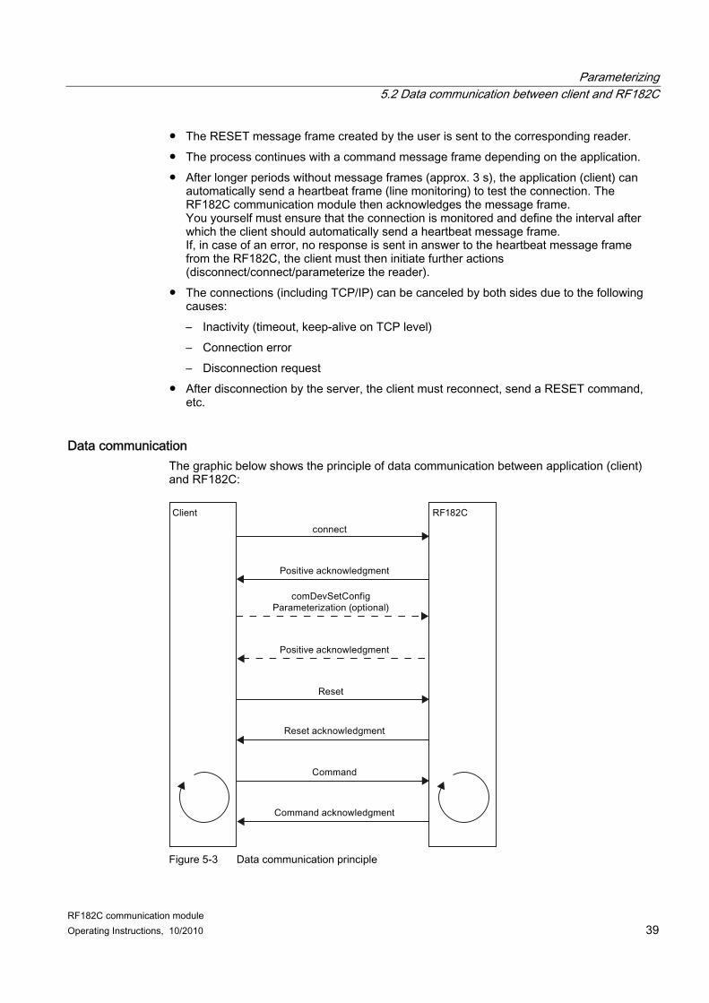
Data communication The graphic below shows the principle of data communication between application (client) and RF182C:
Figure 5-3 Data communication principle
Parameterizing 5.3 Factory setting of the RF182C
RF182C communication module 40 Operating Instructions, 10/2010
5.3 Factory setting of the RF182C Each RF182C is assigned a unique device ID (MAC address) before it leaves the factory. The communication module is addressed via the IP address during configuration and programming. Therefore, you must first assign the IP address data (IP address and subnet mask) to the RF182C so that it can be used in the Ethernet network. An IP address can be assigned to the RF182C using the PST tool or via the web server.
Factory setting ● Default IP address setting: 192.168.0.100 ● Default port setting (default:
– 10001 Reader 1 – 10002 Reader 2
Use the "Primary Setup Tool" (http://support.automation.siemens.com/WW/view/de/19440762) software (V4-0 or higher) to assign an IP address to the communication module.
RF182C communication module Operating Instructions, 10/2010 41
5.4 Assigning the IP address
5.4.1 Overview There are two ways of assigning an IP address to the RF182C communication module: ● Using the "Primary Setup Tool V4-0" ● Via the web server of the communication module Both alternative procedures are described in brief below.
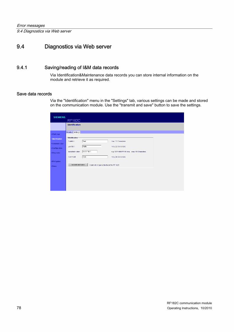
5.4.2 Web server
Procedure 1. Enter the IP address of the communication module in the address field of your browser.
Parameterizing 5.4 Assigning the IP address
RF182C communication module 42 Operating Instructions, 10/2010
The web server of the communication module opens.
Note No contact with web server RF182C If the web server of the communication module does not open, you should make sure that all cables are correctly connected and check whether the RF182C communication module has powered up.
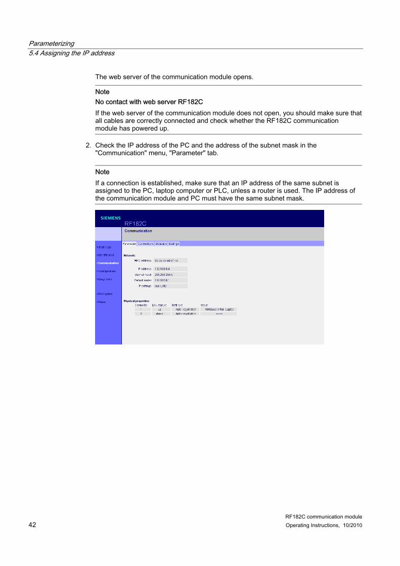
2. Check the IP address of the PC and the address of the subnet mask in the "Communication" menu, "Parameter" tab.
Note If a connection is established, make sure that an IP address of the same subnet is assigned to the PC, laptop computer or PLC, unless a router is used. The IP address of the communication module and PC must have the same subnet mask.
Parameterizing 5.4 Assigning the IP address
RF182C communication module Operating Instructions, 10/2010 43
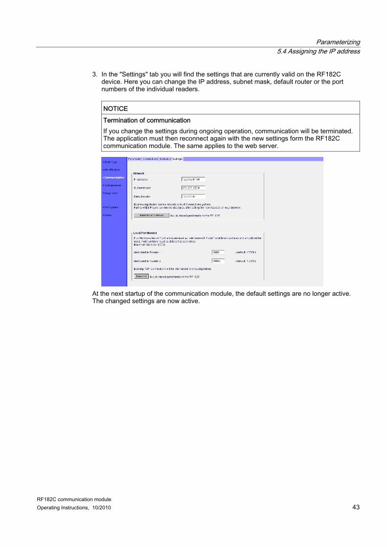
3. In the "Settings" tab you will find the settings that are currently valid on the RF182C device. Here you can change the IP address, subnet mask, default router or the port numbers of the individual readers.
NOTICE
Termination of communication If you change the settings during ongoing operation, communication will be terminated. The application must then reconnect again with the new settings form the RF182C communication module. The same applies to the web server.
At the next startup of the communication module, the default settings are no longer active. The changed settings are now active.
Parameterizing 5.4 Assigning the IP address
RF182C communication module 44 Operating Instructions, 10/2010
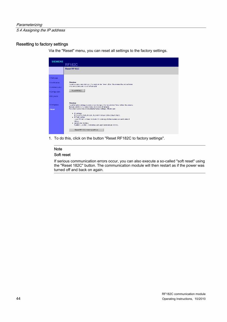
Resetting to factory settings Via the "Reset" menu, you can reset all settings to the factory settings.
1. To do this, click on the button "Reset RF182C to factory settings".
Note Soft reset If serious communication errors occur, you can also execute a so-called "soft reset" using the "Reset 182C" button. The communication module will then restart as if the power was turned off and back on again.
Parameterizing 5.4 Assigning the IP address
RF182C communication module Operating Instructions, 10/2010 45
5.4.3 Primary Setup Tool
Procedure 1. Open the "Primary Setup Tool V4-0" via "Start > SIMATIC > Primary Setup Tool". 2. Select the network card of the PC in the menu under "Settings" and click the "Search"
button A window opens that indicates that a device was found in the network. If no RF182C communication module is shown, make sure that all cables are connected properly and check if the RF182C communication module has started. Check the IP address of the PC and the subnet mask.
Note If a connection is established, make sure that an IP address of the same subnet is assigned to the PC, laptop computer or PLC, unless a router is used. The IP address of the communication module and PC must have the same subnet mask.
Parameterizing 5.4 Assigning the IP address
RF182C communication module 46 Operating Instructions, 10/2010
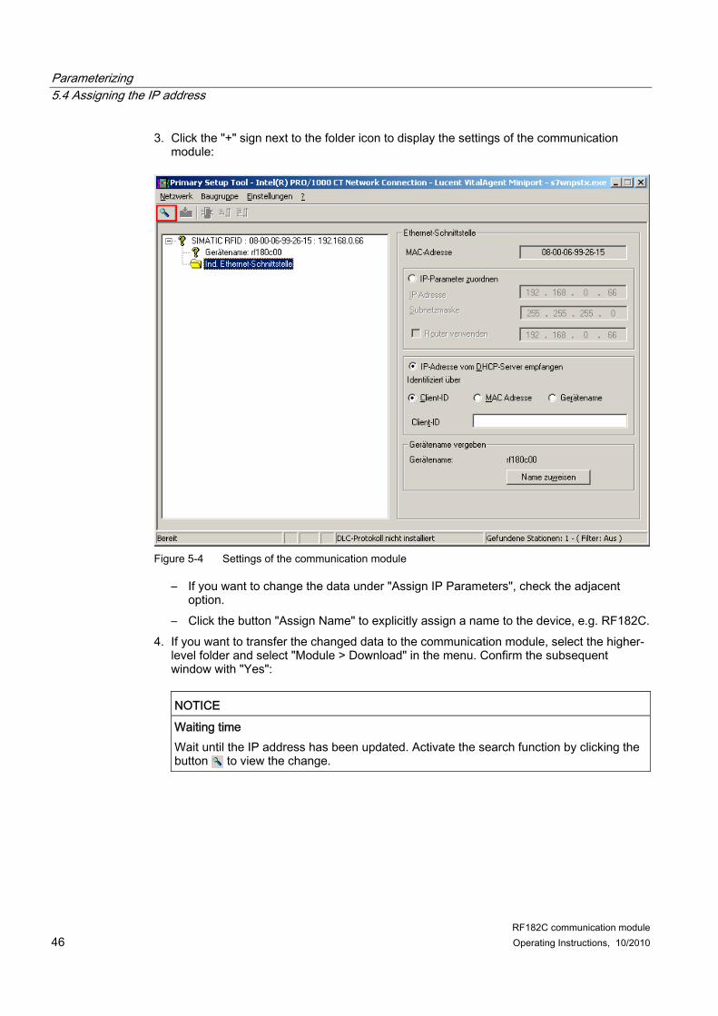
3. Click the "+" sign next to the folder icon to display the settings of the communication module:
Figure 5-4 Settings of the communication module
– If you want to change the data under "Assign IP Parameters", check the adjacent option.
– Click the button "Assign Name" to explicitly assign a name to the device, e.g. RF182C. 4. If you want to transfer the changed data to the communication module, select the higher-
level folder and select "Module > Download" in the menu. Confirm the subsequent window with "Yes":
NOTICE
Waiting time Wait until the IP address has been updated. Activate the search function by clicking the button to view the change.
Parameterizing 5.4 Assigning the IP address
RF182C communication module Operating Instructions, 10/2010 47
Result You can now address the device using a browser or user program.
Note IP address stored on connection block The IP address is stored on the connection block. Therefore, if you replace the base module, no new IP address has to be assigned.
Parameterizing 5.5 Troubleshooting: Assigning the IP address
RF182C communication module 48 Operating Instructions, 10/2010
5.5 Troubleshooting: Assigning the IP address If you are having problems when assigning an IP address to the SIMATIC RF182C communication module, proceed according to the checklist below:
Procedure 1. Connect the RF182C directly or via the hub/switch on your PC/notebook/PLC. Do not
connect any other module/device to the network. Do not switch on the RF182C communication module yet.
2. Remove all other network cables from your PC/notebook and make sure that the RF182C is the only network device connected to your PC/notebook.
3. Now switch on the RF182C. Pay attention to the following LEDs: – The error LEDs 1 and 2 on the device should flash every 3 seconds after run up. – The "SF" LED should be lit. – The "ON" LED should be lit. – The "DC 24 V" LED should be lit. – The "BF" LED should be flashing. – One of the two green link LEDs should be lit (green). One or two "RxTx" LEDs should
flicker depending on the communication load in the network. 4. Start the "Primary Setup Tool V4-0" software and configure the network settings if you
have not already done so. 5. Click "Search" to update the view.
The communication module should now be visible in the "Primary Setup Tool V4-0" software.
6. In the software, click the "+" sign next to the folder icon of the communication module. 7. Check "Assign IP parameter".
– Enter a valid IP address. 8. To transfer the data, select the higher-level folder of the communication module and
select "Module > Load" in the menu. Confirm the subsequent window with "Yes". 9. The IP address should be assigned to the communication module the next time the
"Primary Setup Tool V4-0" inquires.
RF182C communication module Operating Instructions, 10/2010 49
Communication interface 66.1 Overview of commands
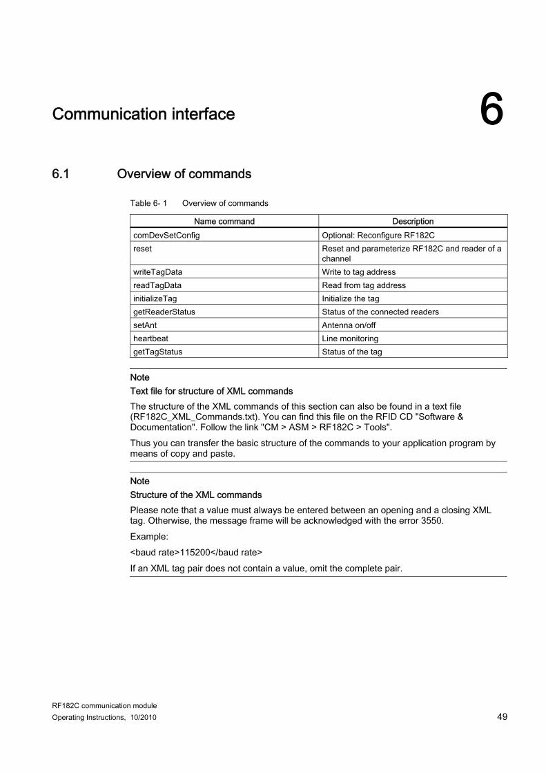
Table 6- 1 Overview of commands
Name command Description comDevSetConfig Optional: Reconfigure RF182C reset Reset and parameterize RF182C and reader of a
channel writeTagData Write to tag address readTagData Read from tag address initializeTag Initialize the tag getReaderStatus Status of the connected readers setAnt Antenna on/off heartbeat Line monitoring getTagStatus Status of the tag
Note Text file for structure of XML commands The structure of the XML commands of this section can also be found in a text file (RF182C_XML_Commands.txt). You can find this file on the RFID CD "Software & Documentation". Follow the link "CM > ASM > RF182C > Tools". Thus you can transfer the basic structure of the commands to your application program by means of copy and paste.
Note Structure of the XML commands Please note that a value must always be entered between an opening and a closing XML tag. Otherwise, the message frame will be acknowledged with the error 3550. Example: <baud rate>115200</baud rate> If an XML tag pair does not contain a value, omit the complete pair.
Communication interface 6.2 Configuration parameters of the RF182C
RF182C communication module 50 Operating Instructions, 10/2010
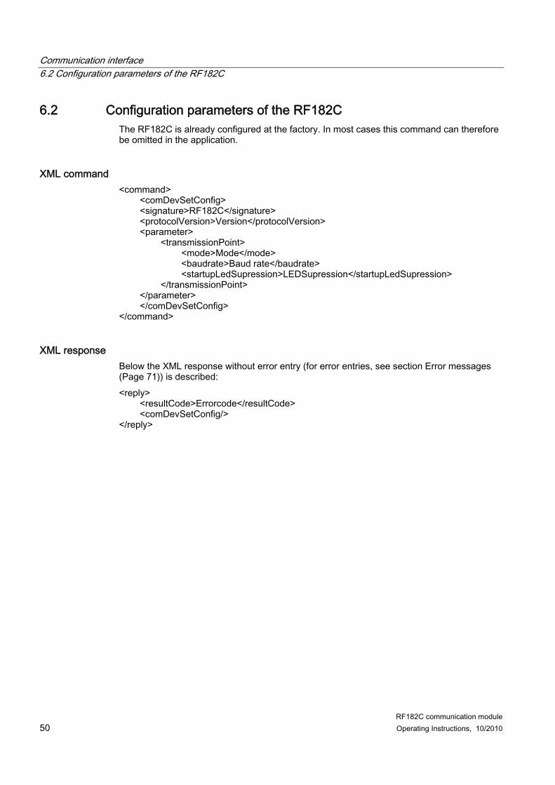
6.2 Configuration parameters of the RF182C The RF182C is already configured at the factory. In most cases this command can therefore be omitted in the application.
XML response Below the XML response without error entry (for error entries, see section Error messages (Page 71)) is described: <reply> <resultCode>Errorcode</resultCode> <comDevSetConfig/> </reply>
Communication interface 6.2 Configuration parameters of the RF182C
RF182C communication module Operating Instructions, 10/2010 51
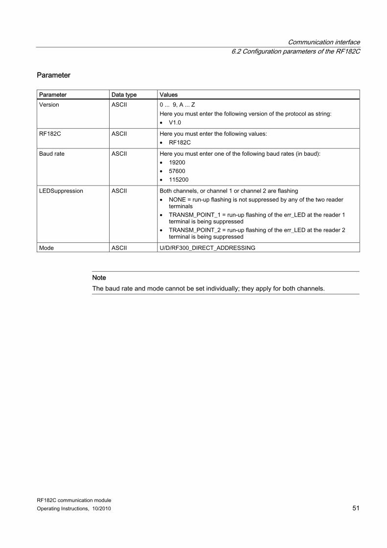
Parameter Parameter Data type Values Version ASCII 0 ... 9, A ... Z
Here you must enter the following version of the protocol as string: • V1.0
RF182C ASCII Here you must enter the following values: • RF182C
Baud rate ASCII Here you must enter one of the following baud rates (in baud): • 19200 • 57600 • 115200
LEDSuppression ASCII Both channels, or channel 1 or channel 2 are flashing • NONE = run-up flashing is not suppressed by any of the two reader
terminals • TRANSM_POINT_1 = run-up flashing of the err_LED at the reader 1
terminal is being suppressed • TRANSM_POINT_2 = run-up flashing of the err_LED at the reader 2
terminal is being suppressed
Mode ASCII U/D/RF300_DIRECT_ADDRESSING
Note The baud rate and mode cannot be set individually; they apply for both channels.
Communication interface 6.3 Input parameters of the RF182C
RF182C communication module 52 Operating Instructions, 10/2010
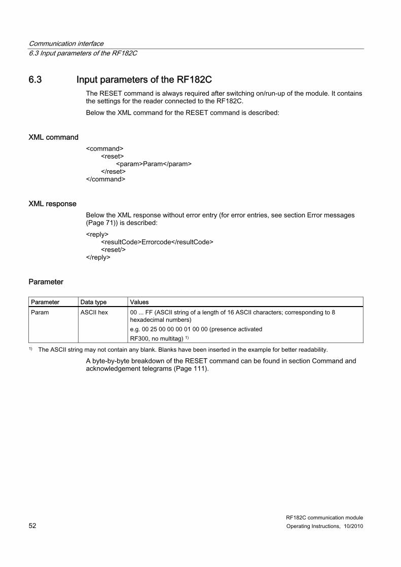
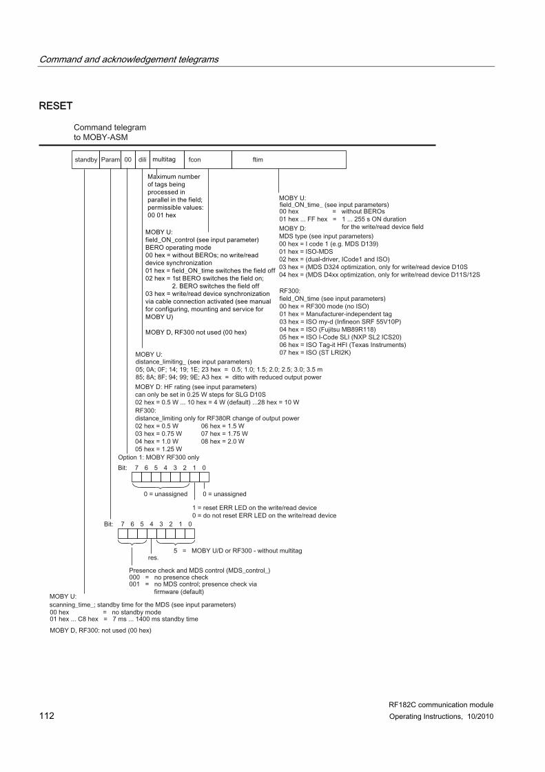
6.3 Input parameters of the RF182C The RESET command is always required after switching on/run-up of the module. It contains the settings for the reader connected to the RF182C. Below the XML command for the RESET command is described:
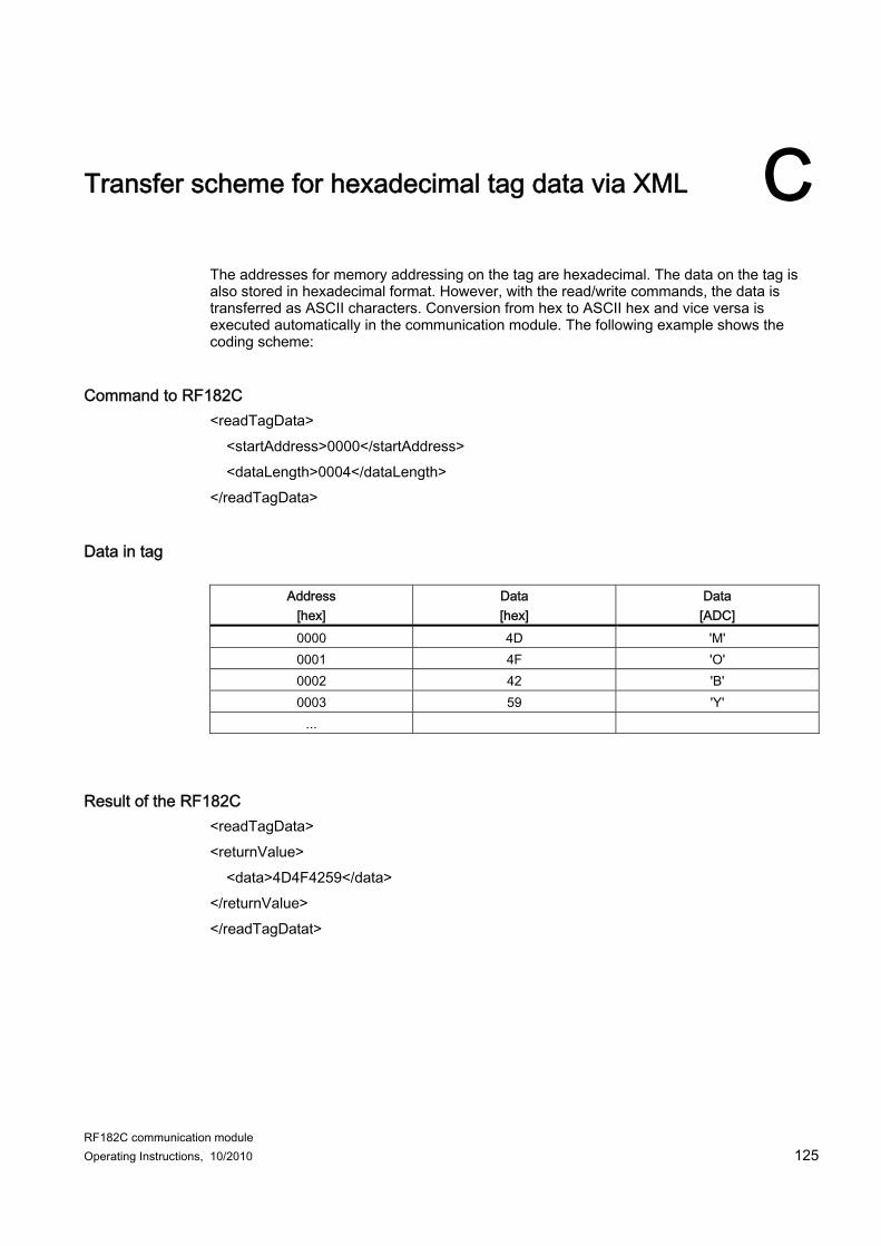
XML command <command> <reset> <param>Param</param> </reset> </command>
XML response Below the XML response without error entry (for error entries, see section Error messages (Page 71)) is described: <reply> <resultCode>Errorcode</resultCode> <reset/> </reply>
Parameter Parameter Data type Values Param ASCII hex 00 ... FF (ASCII string of a length of 16 ASCII characters; corresponding to 8
hexadecimal numbers) e.g. 00 25 00 00 00 01 00 00 (presence activated RF300, no multitag) 1)
1) The ASCII string may not contain any blank. Blanks have been inserted in the example for better readability.
A byte-by-byte breakdown of the RESET command can be found in section Command and acknowledgement telegrams (Page 111).
Communication interface 6.4 Commands of the communication module
RF182C communication module Operating Instructions, 10/2010 53
6.4 Commands of the communication module
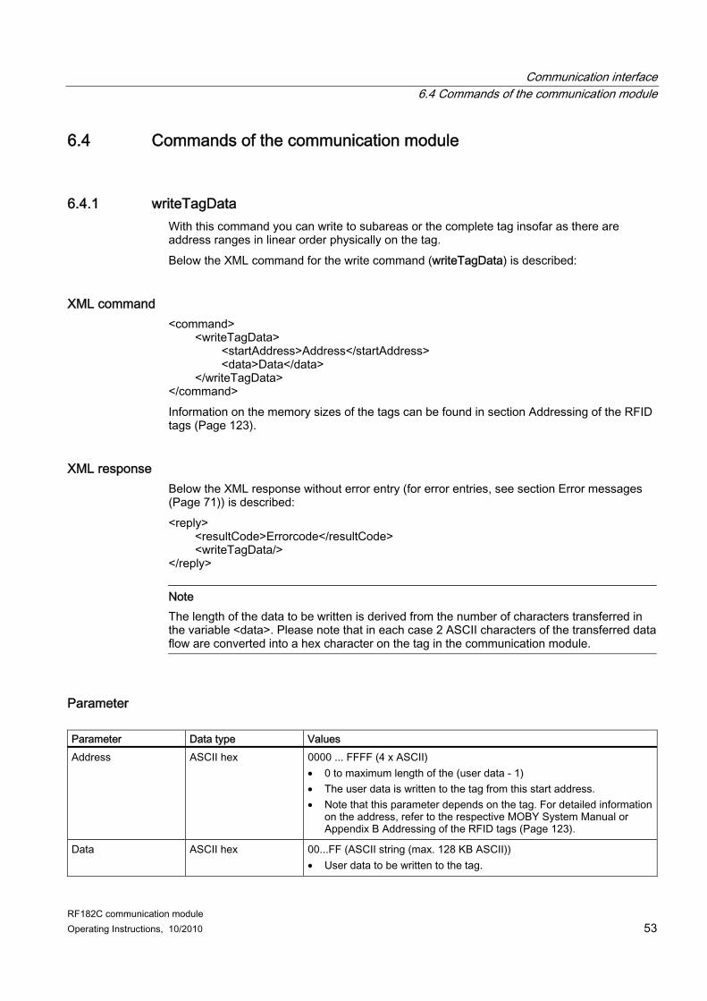
6.4.1 writeTagData With this command you can write to subareas or the complete tag insofar as there are address ranges in linear order physically on the tag. Below the XML command for the write command (writeTagData) is described:
XML command <command> <writeTagData> <startAddress>Address</startAddress> <data>Data</data> </writeTagData> </command> Information on the memory sizes of the tags can be found in section Addressing of the RFID tags (Page 123).
XML response Below the XML response without error entry (for error entries, see section Error messages (Page 71)) is described: <reply> <resultCode>Errorcode</resultCode> <writeTagData/> </reply>
Note The length of the data to be written is derived from the number of characters transferred in the variable <data>. Please note that in each case 2 ASCII characters of the transferred data flow are converted into a hex character on the tag in the communication module.
Parameter Parameter Data type Values Address ASCII hex 0000 ... FFFF (4 x ASCII)
• 0 to maximum length of the (user data - 1) • The user data is written to the tag from this start address. • Note that this parameter depends on the tag. For detailed information
on the address, refer to the respective MOBY System Manual or Appendix B Addressing of the RFID tags (Page 123).
Data ASCII hex 00...FF (ASCII string (max. 128 KB ASCII)) • User data to be written to the tag.
Communication interface 6.4 Commands of the communication module
RF182C communication module 54 Operating Instructions, 10/2010
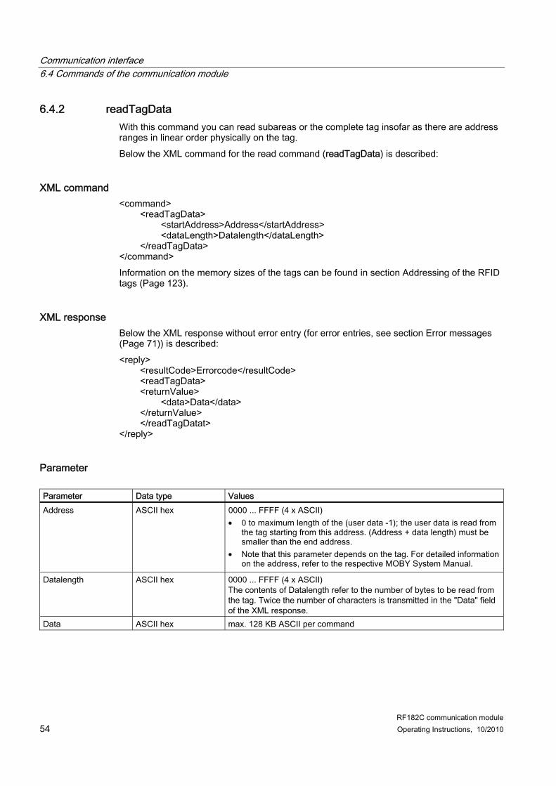
6.4.2 readTagData With this command you can read subareas or the complete tag insofar as there are address ranges in linear order physically on the tag. Below the XML command for the read command (readTagData) is described:
XML command <command> <readTagData> <startAddress>Address</startAddress> <dataLength>Datalength</dataLength> </readTagData> </command> Information on the memory sizes of the tags can be found in section Addressing of the RFID tags (Page 123).
XML response Below the XML response without error entry (for error entries, see section Error messages (Page 71)) is described: <reply> <resultCode>Errorcode</resultCode> <readTagData> <returnValue> <data>Data</data> </returnValue> </readTagDatat> </reply>
Parameter Parameter Data type Values Address ASCII hex 0000 ... FFFF (4 x ASCII)
• 0 to maximum length of the (user data -1); the user data is read from the tag starting from this address. (Address + data length) must be smaller than the end address.
• Note that this parameter depends on the tag. For detailed information on the address, refer to the respective MOBY System Manual.
Datalength ASCII hex 0000 ... FFFF (4 x ASCII) The contents of Datalength refer to the number of bytes to be read from the tag. Twice the number of characters is transmitted in the "Data" field of the XML response.
Data ASCII hex max. 128 KB ASCII per command
Communication interface 6.4 Commands of the communication module
RF182C communication module Operating Instructions, 10/2010 55
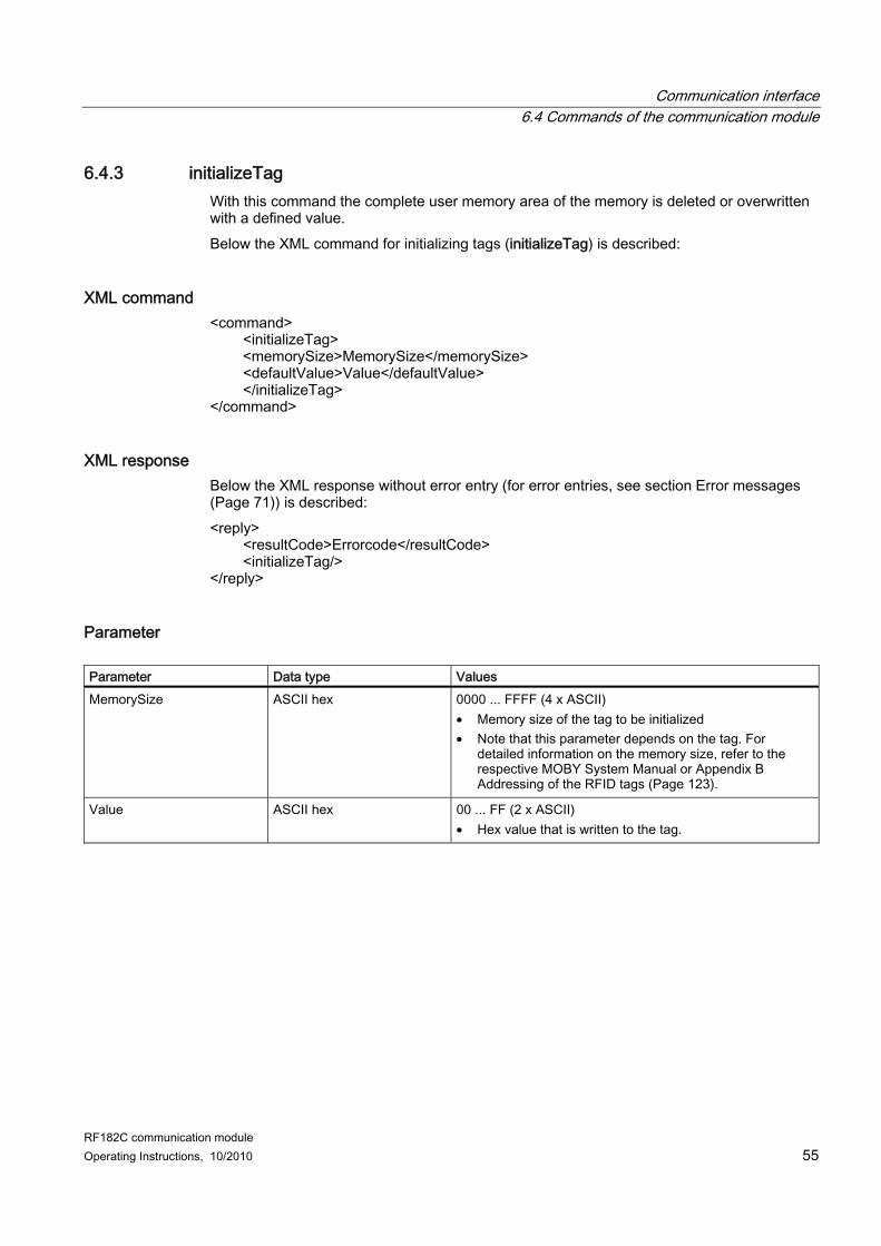
6.4.3 initializeTag With this command the complete user memory area of the memory is deleted or overwritten with a defined value. Below the XML command for initializing tags (initializeTag) is described:
XML command <command> <initializeTag> <memorySize>MemorySize</memorySize> <defaultValue>Value</defaultValue> </initializeTag> </command>
XML response Below the XML response without error entry (for error entries, see section Error messages (Page 71)) is described: <reply> <resultCode>Errorcode</resultCode> <initializeTag/> </reply>
Parameter Parameter Data type Values MemorySize ASCII hex 0000 ... FFFF (4 x ASCII)
• Memory size of the tag to be initialized • Note that this parameter depends on the tag. For
detailed information on the memory size, refer to the respective MOBY System Manual or Appendix B Addressing of the RFID tags (Page 123).
Value ASCII hex 00 ... FF (2 x ASCII) • Hex value that is written to the tag.
Communication interface 6.4 Commands of the communication module
RF182C communication module 56 Operating Instructions, 10/2010
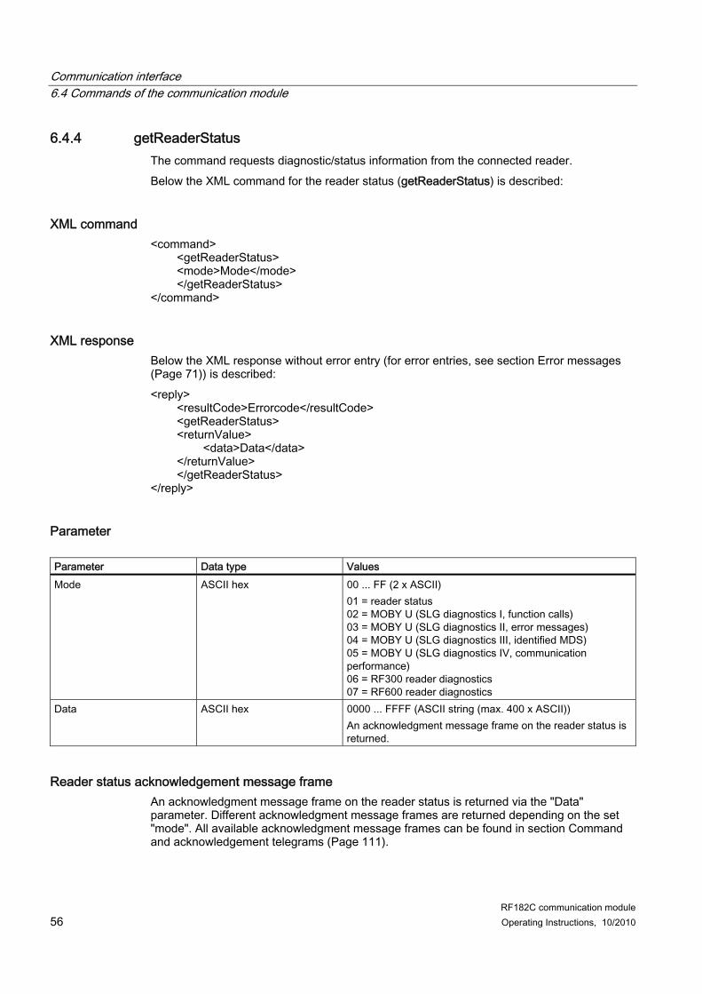
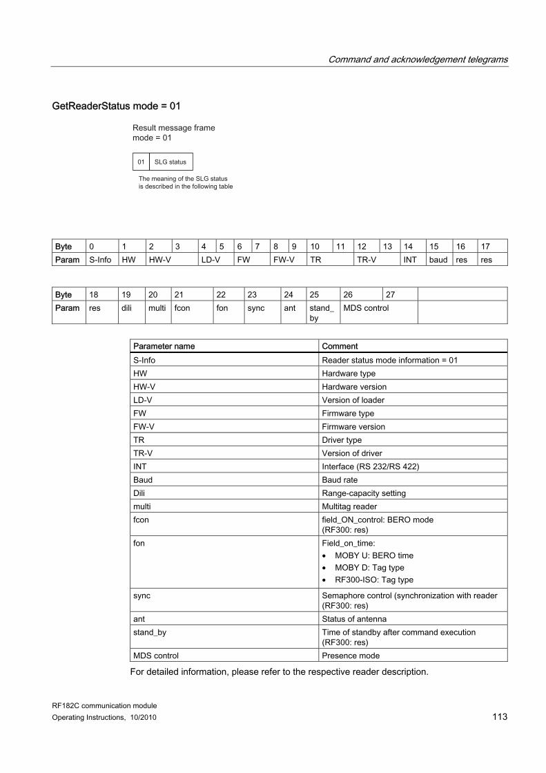
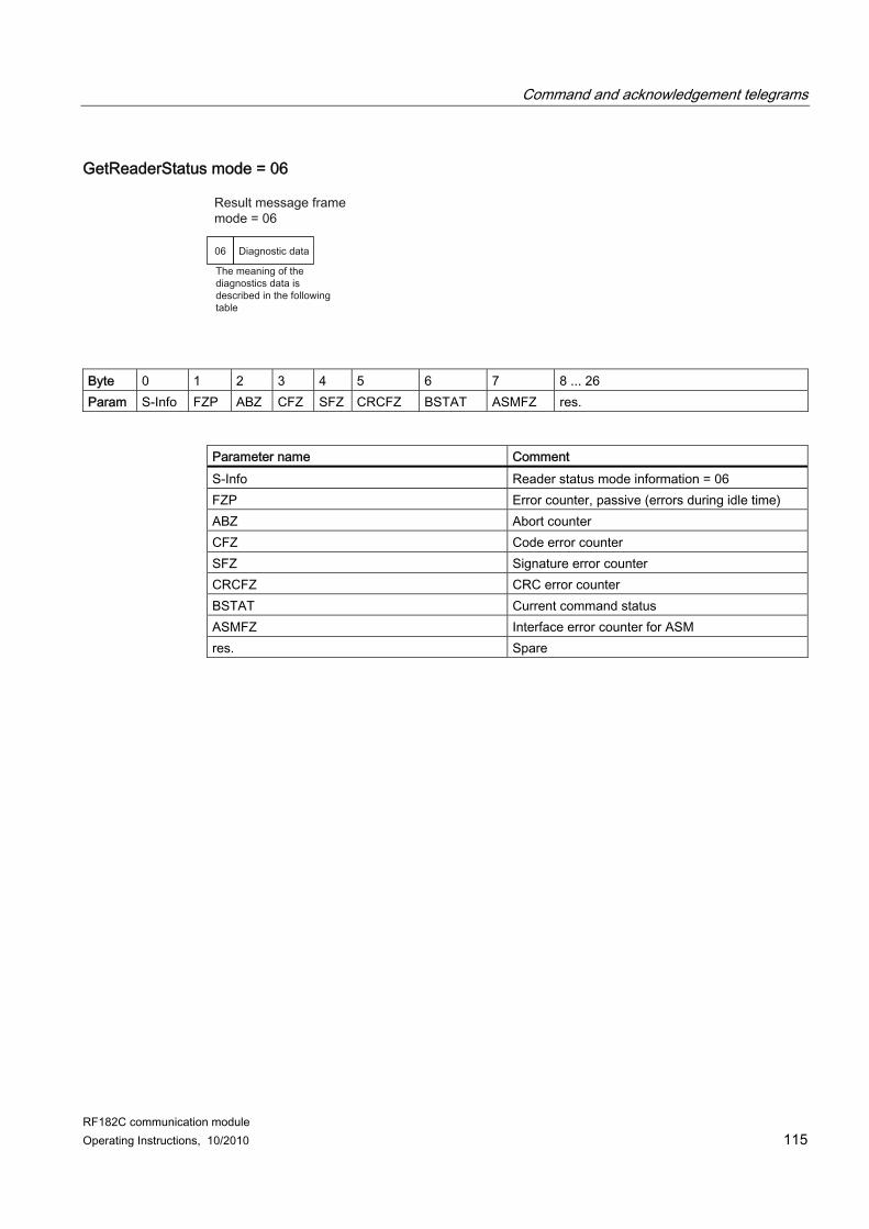
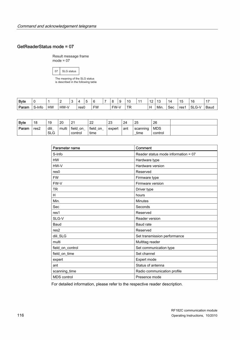
6.4.4 getReaderStatus The command requests diagnostic/status information from the connected reader. Below the XML command for the reader status (getReaderStatus) is described:
XML command <command> <getReaderStatus> <mode>Mode</mode> </getReaderStatus> </command>
XML response Below the XML response without error entry (for error entries, see section Error messages (Page 71)) is described: <reply> <resultCode>Errorcode</resultCode> <getReaderStatus> <returnValue> <data>Data</data> </returnValue> </getReaderStatus> </reply>
Parameter Parameter Data type Values Mode ASCII hex 00 ... FF (2 x ASCII)
01 = reader status 02 = MOBY U (SLG diagnostics I, function calls) 03 = MOBY U (SLG diagnostics II, error messages) 04 = MOBY U (SLG diagnostics III, identified MDS) 05 = MOBY U (SLG diagnostics IV, communication performance) 06 = RF300 reader diagnostics 07 = RF600 reader diagnostics
Data ASCII hex 0000 ... FFFF (ASCII string (max. 400 x ASCII)) An acknowledgment message frame on the reader status is returned.
Reader status acknowledgement message frame An acknowledgment message frame on the reader status is returned via the "Data" parameter. Different acknowledgment message frames are returned depending on the set "mode". All available acknowledgment message frames can be found in section Command and acknowledgement telegrams (Page 111).
Communication interface 6.4 Commands of the communication module
RF182C communication module Operating Instructions, 10/2010 57
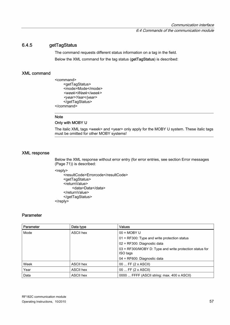
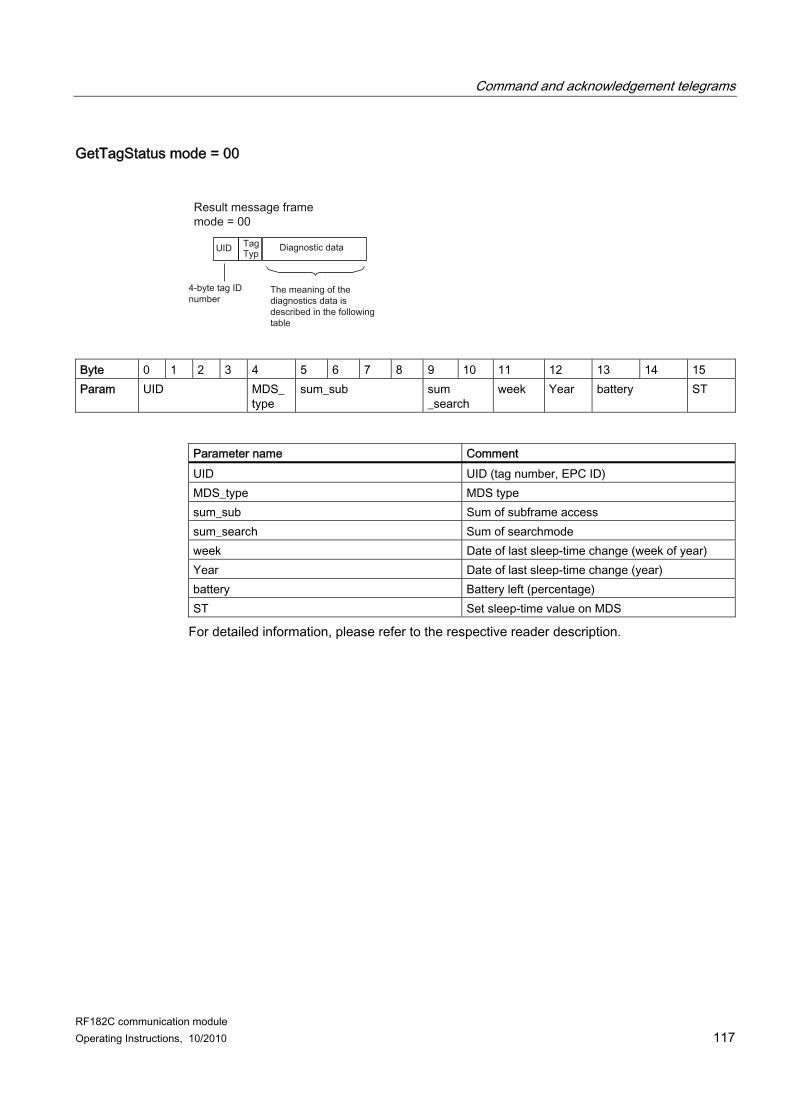
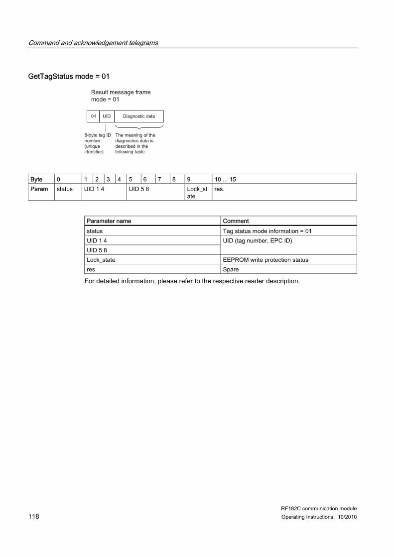
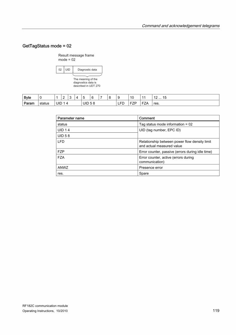
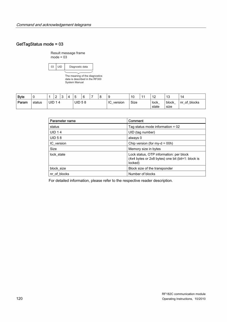
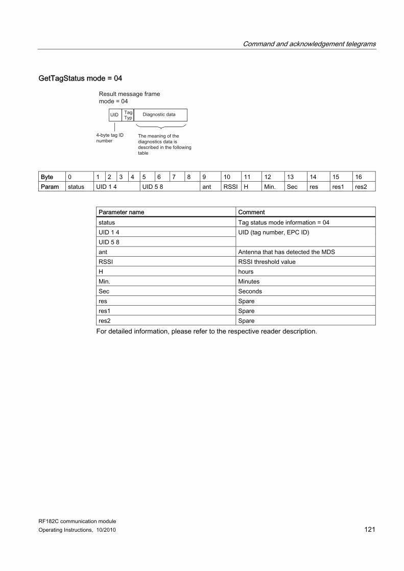
6.4.5 getTagStatus The command requests different status information on a tag in the field. Below the XML command for the tag status (getTagStatus) is described:
XML command <command> <getTagStatus> <mode>Mode</mode> <week>Week</week> <year>Year</year> </getTagStatus> </command>
Note Only with MOBY U The italic XML tags <week> and <year> only apply for the MOBY U system. These italic tags must be omitted for other MOBY systems!
XML response Below the XML response without error entry (for error entries, see section Error messages (Page 71)) is described: <reply> <resultCode>Errorcode</resultCode> <getTagStatus> <returnValue> <data>Data</data> </returnValue> </getTagStatus> </reply>
Parameter Parameter Data type Values Mode ASCII hex 00 = MOBY U
01 = RF300: Type and write protection status 02 = RF300: Diagnostic data 03 = RF300/MOBY D: Type and write protection status for ISO tags 04 = RF600: Diagnostic data
Week ASCII hex 00 ... FF (2 x ASCII) Year ASCII hex 00 ... FF (2 x ASCII) Data ASCII hex 0000 ... FFFF (ASCII string: max. 400 x ASCII)
Communication interface 6.4 Commands of the communication module
RF182C communication module 58 Operating Instructions, 10/2010
Tag status acknowledgement message frame An acknowledgment message frame on the tag status is returned via the "Data" parameter. Different acknowledgment message frames are returned depending on the set "mode". All available acknowledgment message frames can be found in section Command and acknowledgement telegrams (Page 111).
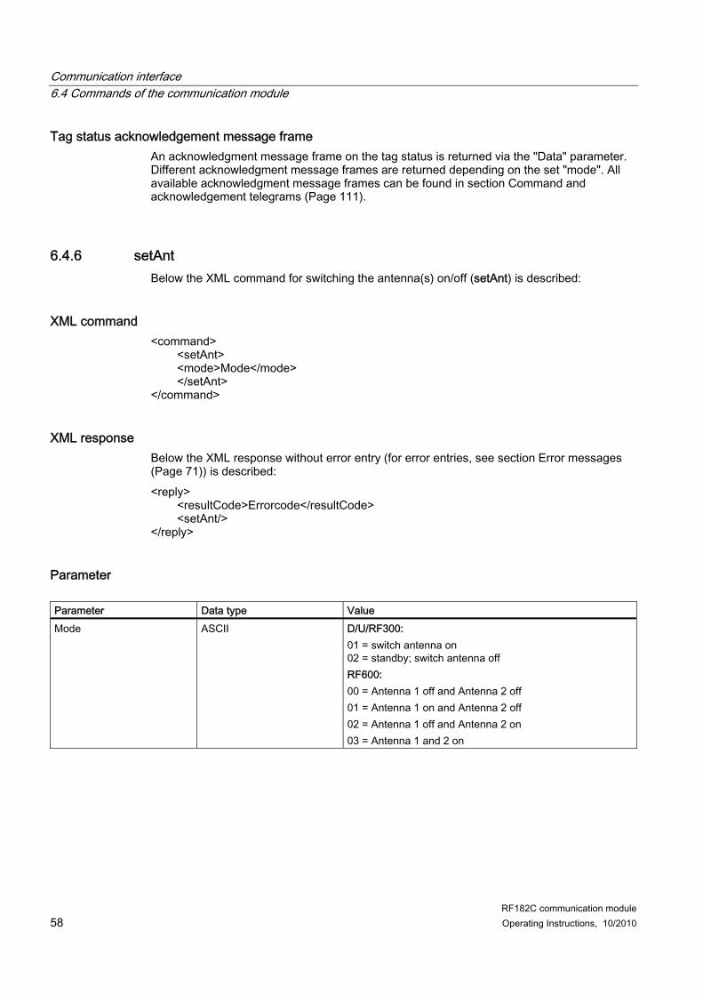
6.4.6 setAnt Below the XML command for switching the antenna(s) on/off (setAnt) is described:
XML command <command> <setAnt> <mode>Mode</mode> </setAnt> </command>
XML response Below the XML response without error entry (for error entries, see section Error messages (Page 71)) is described: <reply> <resultCode>Errorcode</resultCode> <setAnt/> </reply>
Parameter Parameter Data type Value Mode ASCII D/U/RF300:
01 = switch antenna on 02 = standby; switch antenna off RF600: 00 = Antenna 1 off and Antenna 2 off 01 = Antenna 1 on and Antenna 2 off 02 = Antenna 1 off and Antenna 2 on 03 = Antenna 1 and 2 on
Communication interface 6.4 Commands of the communication module
RF182C communication module Operating Instructions, 10/2010 59
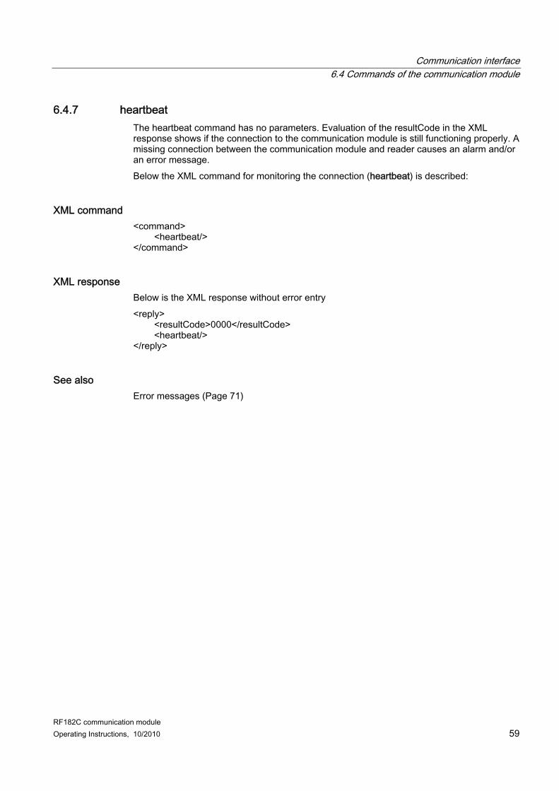
6.4.7 heartbeat The heartbeat command has no parameters. Evaluation of the resultCode in the XML response shows if the connection to the communication module is still functioning properly. A missing connection between the communication module and reader causes an alarm and/or an error message. Below the XML command for monitoring the connection (heartbeat) is described:
XML command <command> <heartbeat/> </command>
XML response Below is the XML response without error entry <reply> <resultCode>0000</resultCode> <heartbeat/> </reply>
See also Error messages (Page 71)
Communication interface 6.5 Asynchronous message frames
RF182C communication module 60 Operating Instructions, 10/2010
6.5 Asynchronous message frames
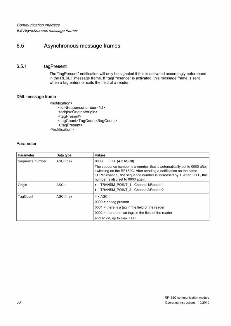
6.5.1 tagPresent The "tagPresent" notification will only be signaled if this is activated accordingly beforehand in the RESET message frame. If "tagPresence" is activated, this message frame is sent when a tag enters or exits the field of a reader.
XML message frame <notification> <id>Sequencenumber</id> <origin>Origin</origin> <tagPresent> <tagCount>TagCount</tagCount> </tagPresent> </notification>
Parameter Parameter Data type Values Sequence number ASCII hex 0000 ... FFFF (4 x ASCII)
The sequence number is a number that is automatically set to 0000 after switching on the RF182C. After sending a notification on the same TCPIP channel, the sequence number is increased by 1. After FFFF, this number is also set to 0000 again.
TagCount ASCII hex 4 x ASCII 0000 = no tag present 0001 = there is a tag in the field of the reader 0002 = there are two tags in the field of the reader and so on, up to max. 00FF
Communication interface 6.5 Asynchronous message frames
RF182C communication module Operating Instructions, 10/2010 61
6.5.2 alarm If no command is pending, the RF182C communication module sends an alarm.
Parameter Parameter Data type Values Sequence number ASCII hex 0000 ... FFFF (4 x ASCII)
The sequence number is a number that is automatically set to 0000 after switching on the RF182C. After sending an alarm on the same TCPIP channel, the sequence number is increased by 1. After FFFF, this number is also set to 0000 again.
Origin ASCII 0 .. 9, A ... Z Source channel TRANSM_POINT_1 or TRANSM_POINT_2
DeviceName ASCII Name of the device (default: RF182C) The device name can be up to 256 bytes long.
Time ASCII hex 00000000...FFFFFFFF (8 x ASCII) Time of the alarm in milliseconds This time is reset to 0000 when the RF182C is switched on. It cannot be set by the user. It is therefore a relative time
Error code ASCII hex 0000 ... FFFF (4 x ASCII) The error code specifies the cause that triggered this alarm message frame. More information on the error codes can be found in section Error messages of the RF182C (Page 72).
Communication interface 6.5 Asynchronous message frames
RF182C communication module 62 Operating Instructions, 10/2010
RF182C communication module Operating Instructions, 10/2010 63
Maintenance and Service 77.1 Replacing the RF182C communication module
Initial situation ● The RF182C communication module is already mounted. A new RF182C communication
module of the same type should be installed. ● The RF182C is wired up and operating.
Procedure 1. Remove the 4 fixing screws from the connection block and pull the connection block off
the communication module.
Note If you disassemble the connection block during operation, only the power supply will be looped through. Ethernet communication will be interrupted during module replacement from this node onwards. For more information, refer to section Loop-through of Ethernet and supply voltage (Page 30).
2. On the communication module, remove the screwed M12 plug-in connections to the readers.
3. Remove the fixing screws from the communication module and remove it. 4. Locate the new communication module and screw it down firmly. 5. Place the connection block on the new communication module and tighten the 4 fixing
screws.
Result Since the IP address of the communication module remains saved in the connection block, the new RF182C communication module is included in the data communication by the Ethernet controller.
Note If the connection block is replaced in addition to the base unit, the RF182C may not start up automatically. In this case, proceed as follows:
Maintenance and Service 7.1 Replacing the RF182C communication module
RF182C communication module 64 Operating Instructions, 10/2010
What should I do if the RF182C can no longer be addressed If the connection block is replaced in addition to the base unit, it is possible that the RF182C can no longer be addressed. This is indicated by a permanently lit or flashing BF LED. In this case, check the network configuration. Load (e.g. using the PST tool) the required network parameters into the RF182C. Check the diagnostic messages via the web server or check the settings of the IP address or the port number setting.
See also Parameterizing (Page 35)
Maintenance and Service 7.2 Firmware update
RF182C communication module Operating Instructions, 10/2010 65
7.2 Firmware update The firmware for the RF182C communication module can be updated via the Ethernet interface. You can the start the firmware update via the web server of the communication module.
Preconditions ● The communication module is connected to the PC via Ethernet. ● Exit all applications before you start the firmware update.
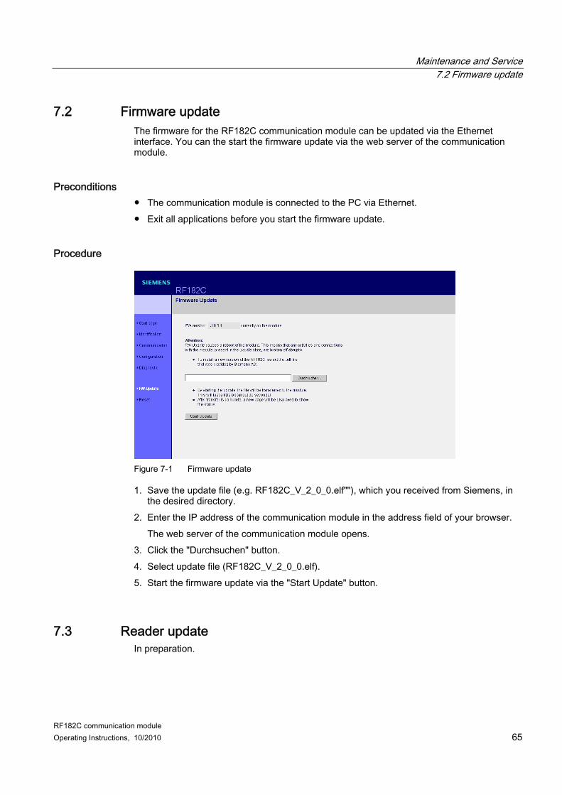
Procedure
Figure 7-1 Firmware update
1. Save the update file (e.g. RF182C_V_2_0_0.elf""), which you received from Siemens, in the desired directory.
2. Enter the IP address of the communication module in the address field of your browser. The web server of the communication module opens.
3. Click the "Durchsuchen" button. 4. Select update file (RF182C_V_2_0_0.elf). 5. Start the firmware update via the "Start Update" button.
7.3 Reader update In preparation.
Maintenance and Service 7.3 Reader update
RF182C communication module 66 Operating Instructions, 10/2010
RF182C communication module Operating Instructions, 10/2010 67
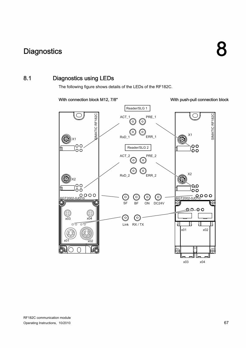
Diagnostics 88.1 Diagnostics using LEDs
The following figure shows details of the LEDs of the RF182C. With connection block M12, 7/8'' With push-pull connection block
Diagnostics 8.1 Diagnostics using LEDs
RF182C communication module 68 Operating Instructions, 10/2010
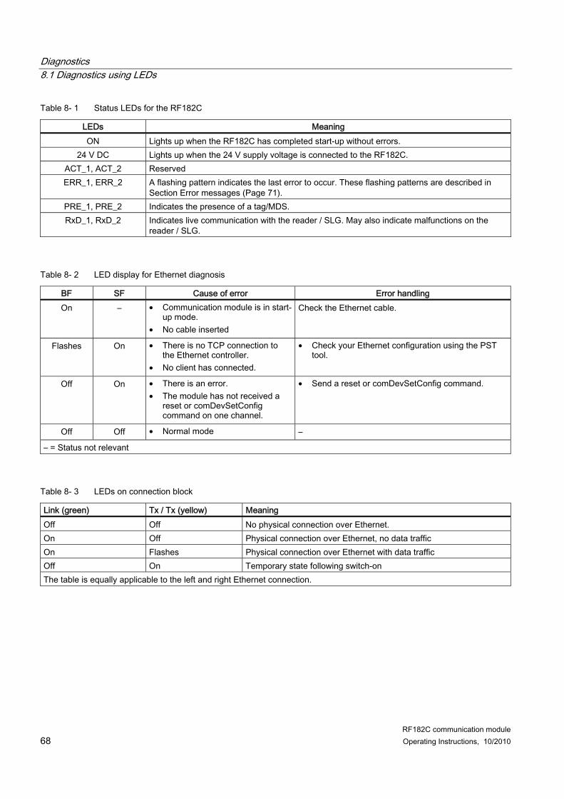
Table 8- 1 Status LEDs for the RF182C
LEDs Meaning ON Lights up when the RF182C has completed start-up without errors.
24 V DC Lights up when the 24 V supply voltage is connected to the RF182C. ACT_1, ACT_2 Reserved ERR_1, ERR_2 A flashing pattern indicates the last error to occur. These flashing patterns are described in
Section Error messages (Page 71). PRE_1, PRE_2 Indicates the presence of a tag/MDS. RxD_1, RxD_2 Indicates live communication with the reader / SLG. May also indicate malfunctions on the
reader / SLG.
Table 8- 2 LED display for Ethernet diagnosis
BF SF Cause of error Error handling On – • Communication module is in start-
up mode. • No cable inserted
Check the Ethernet cable.
Flashes On • There is no TCP connection to the Ethernet controller.
• No client has connected.
• Check your Ethernet configuration using the PST tool.
Off On • There is an error. • The module has not received a
reset or comDevSetConfig command on one channel.
• Send a reset or comDevSetConfig command.
Off Off • Normal mode –
– = Status not relevant
Table 8- 3 LEDs on connection block
Link (green) Tx / Tx (yellow) Meaning Off Off No physical connection over Ethernet. On Off Physical connection over Ethernet, no data traffic On Flashes Physical connection over Ethernet with data traffic Off On Temporary state following switch-on The table is equally applicable to the left and right Ethernet connection.
Diagnostics 8.1 Diagnostics using LEDs
RF182C communication module Operating Instructions, 10/2010 69
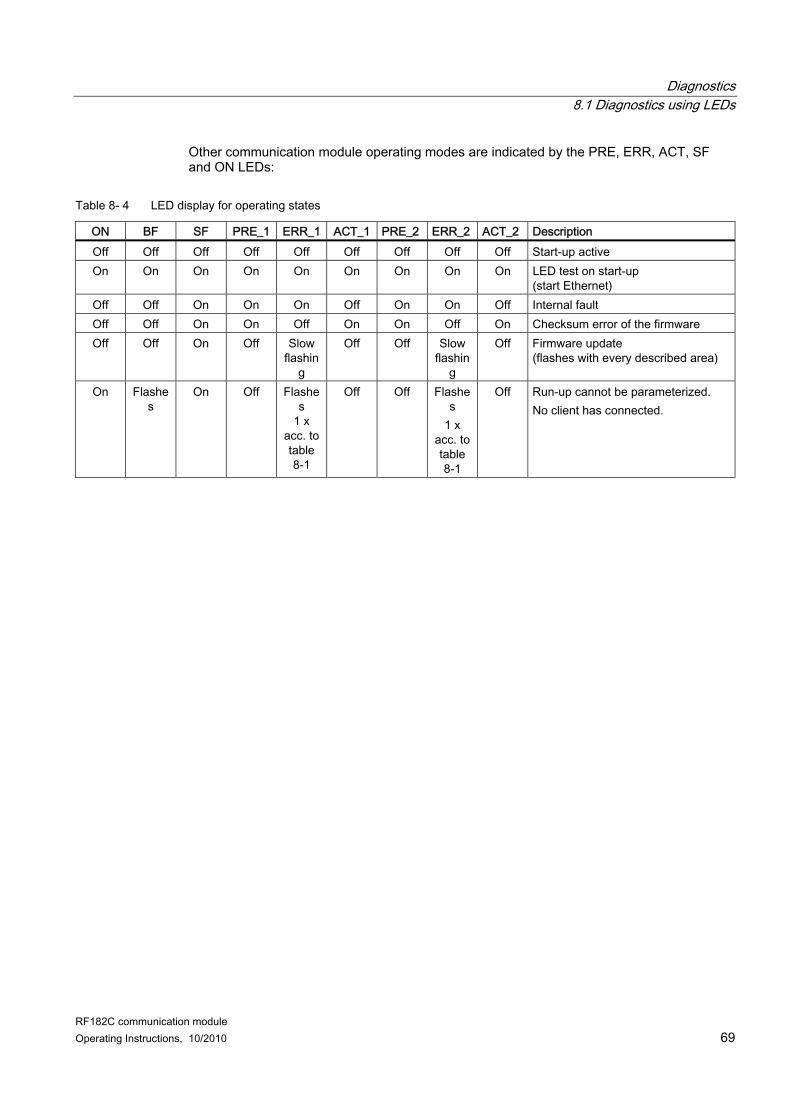
Other communication module operating modes are indicated by the PRE, ERR, ACT, SF and ON LEDs:
Table 8- 4 LED display for operating states
ON BF SF PRE_1 ERR_1 ACT_1 PRE_2 ERR_2 ACT_2 Description Off Off Off Off Off Off Off Off Off Start-up active On On On On On On On On On LED test on start-up
(start Ethernet) Off Off On On On Off On On Off Internal fault Off Off On On Off On On Off On Checksum error of the firmware Off Off On Off Slow
flashing
Off Off Slow flashin
g
Off Firmware update (flashes with every described area)
On Flashes
On Off Flashes
1 x acc. to table 8-1
Off Off Flashes
1 x acc. to table 8-1
Off Run-up cannot be parameterized. No client has connected.
Diagnostics 8.1 Diagnostics using LEDs
RF182C communication module 70 Operating Instructions, 10/2010
RF182C communication module Operating Instructions, 10/2010 71
Error messages 99.1 Response without error entry
Below the XML response without error entry is described:
XML response <reply> <resultCode>0000</resultCode> <Name of the output command, e.g. reset/> </reply>
9.2 Response with error entry Below the XML response with error entry is described:
XML response <reply> <resultCode>Errorcode</resultCode> <Name of the output command, e.g. reset/> </reply> The following table describes the possible error codes (resultCodes). The error codes are coded in 4 bytes.
Error messages 9.3 Error messages of the RF182C
RF182C communication module 72 Operating Instructions, 10/2010
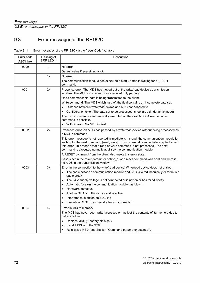
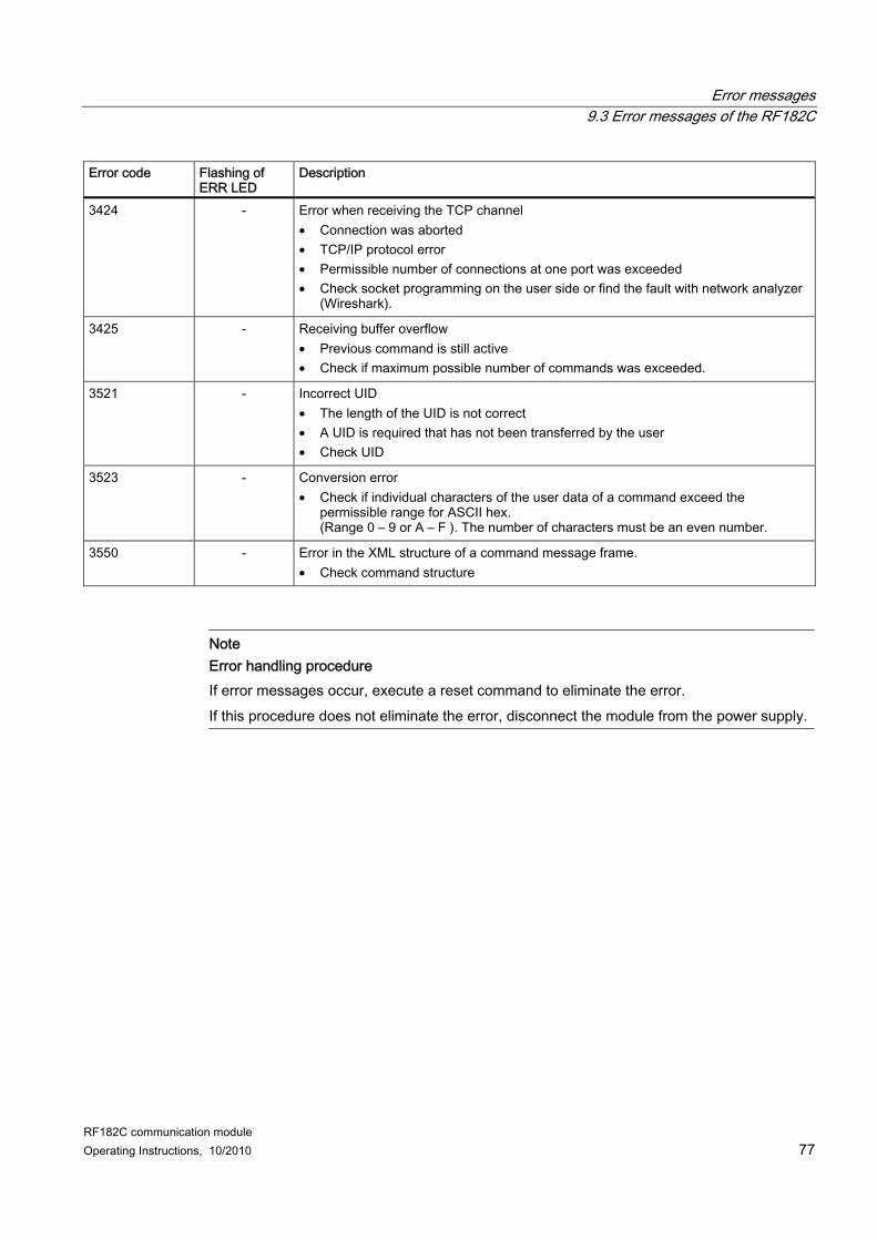
9.3 Error messages of the RF182C
Table 9- 1 Error messages of the RF182C via the "resultCode" variable
Error code ASCII hex
Flashing of ERR LED 1)
Description
0000 – No error Default value if everything is ok.
1x No error The communication module has executed a start-up and is waiting for a RESET command.
0001 2x Presence error: The MDS has moved out of the write/read device's transmission window. The MOBY command was executed only partially. Read command: No data is being transmitted to the client. Write command: The MDS which just left the field contains an incomplete data set. • Distance between write/read device and MDS not adhered to • Configuration error: The data set to be processed is too large (in dynamic mode) The next command is automatically executed on the next MDS. A read or write command is possible. • With timeout: No MDS in field
0002 2x Presence error: An MDS has passed by a write/read device without being processed by a MOBY command. This error message is not reported immediately. Instead, the communication module is waiting for the next command (read, write). This command is immediately replied to with this error. This means that a read or write command is not processed. The next command is executed normally again by the communication module. A RESET command from the client also resets this error state. Bit 2 is set in the reset parameter option_1, or a reset command was sent and there is no MDS in the transmission window.
0003 3x Error in the connection to the write/read device. Write/read device does not answer. • The cable between communication module and SLG is wired incorrectly or there is a
cable break • The 24 V supply voltage is not connected or is not on or has failed briefly • Automatic fuse on the communication module has blown • Hardware defective • Another SLG is in the vicinity and is active • Interference injection on SLG line • Execute a RESET command after error correction
0004 4x Error in MDS's memory The MDS has never been write-accessed or has lost the contents of its memory due to battery failure. • Replace MDS (if battery bit is set). • Install MDS with the STG. • Reinitialize MSD (see Section "Command parameter settings").
Error messages 9.3 Error messages of the RF182C
RF182C communication module Operating Instructions, 10/2010 73
Error code ASCII hex
Flashing of ERR LED 1)
Description
0005 5x Unknown command The client is sending an uninterpretable command to the communication module. • Check the XML command • The MDS reported an address error
0006 6x Field interference on write/read device The write/read device is receiving interference from its environment. • The distance between two write/read devices is too small and does not correspond
to the configuration guidelines • The connecting cable to the write/read device is defective or too long or does not
comply with the specification • MOBY U: MDS has left the field during communication. • MOBY U: Communication between write/read device and MDS was terminated by
interference (e.g. person/foreign body moving between write/read device and MDS).
0007 7x Too many transmit errors The MDS was not able to correctly receive the command or the write data from the communication module even after several attempts. • The MDS is positioned exactly on the boundary of the transmission window. • Data transmission to the MDS is being affected by external interference.
0008 8x CRC sending error • The receiver monitor has detected at least one fault during transmission.
– Cause same as error 0006 • MDS signaling CRC error frequently.
– The MDS is positioned exactly on the boundary of the write/read device. – The hardware of the MDS and/or write/read device is defective.
0009 9x Only during initialization: CRC error during acknowledgment receipt from MDS • Cause same as error 0006
000A 10x Only during initialization: MDS is unable to perform the initialization command. • MDS is defective.
000B 11x MOBY U: Memory of MDS cannot be read correctly. 000C 12x Memory of the MDS cannot be write-accessed.
• Memory of the MDS is defective. • EEPROM MDS was written too frequently and has reached the end of its service life
000D 13x Address error The address area of the MDS was exceeded. • Check the XML command • The MDS is not the right type. • RF300: Attempted write access to write-protected areas (OTP area)
Error messages 9.3 Error messages of the RF182C
RF182C communication module 74 Operating Instructions, 10/2010
Error code ASCII hex
Flashing of ERR LED 1)
Description
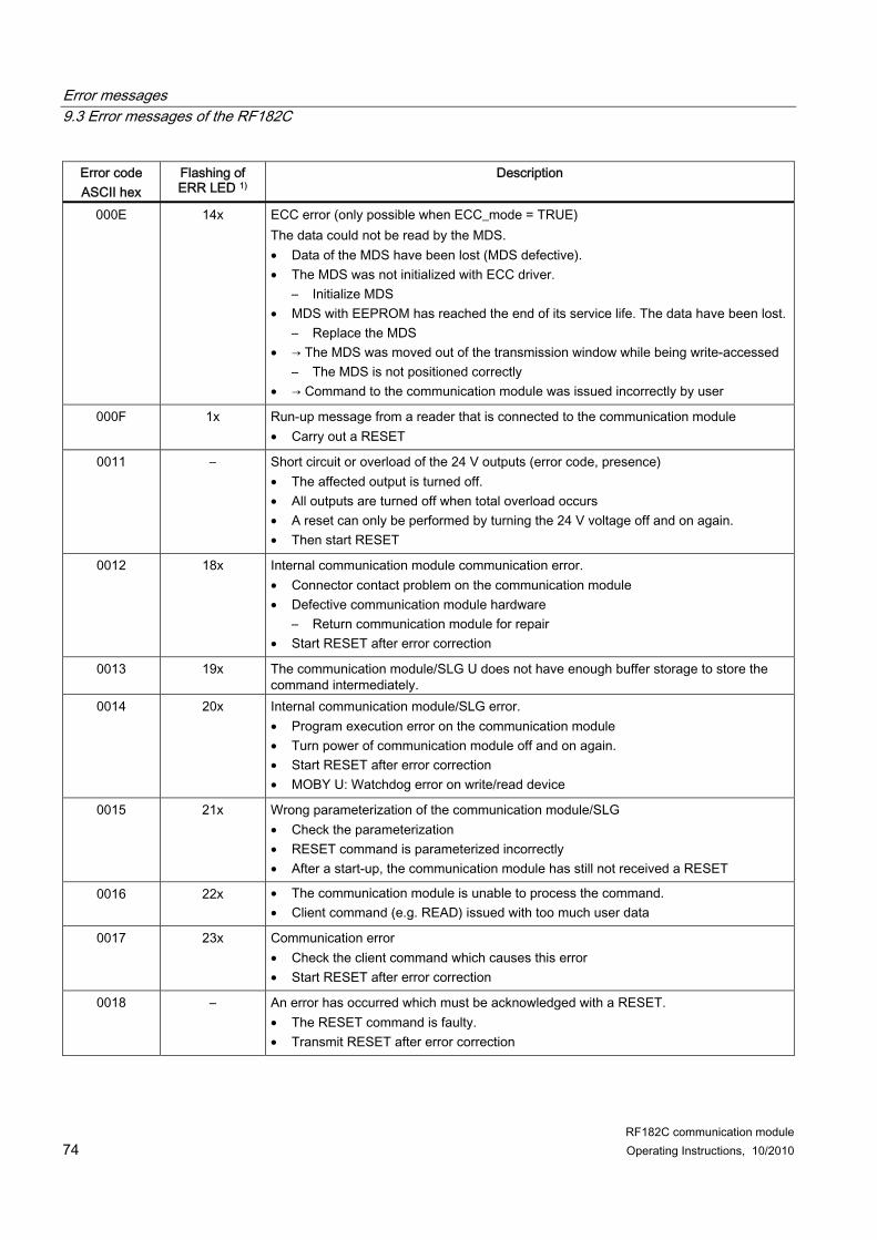
000E 14x ECC error (only possible when ECC_mode = TRUE) The data could not be read by the MDS. • Data of the MDS have been lost (MDS defective). • The MDS was not initialized with ECC driver.
– Initialize MDS • MDS with EEPROM has reached the end of its service life. The data have been lost.
– Replace the MDS • → The MDS was moved out of the transmission window while being write-accessed
– The MDS is not positioned correctly • → Command to the communication module was issued incorrectly by user
000F 1x
Run-up message from a reader that is connected to the communication module • Carry out a RESET
0011 – Short circuit or overload of the 24 V outputs (error code, presence) • The affected output is turned off. • All outputs are turned off when total overload occurs • A reset can only be performed by turning the 24 V voltage off and on again. • Then start RESET
0012 18x Internal communication module communication error. • Connector contact problem on the communication module • Defective communication module hardware
– Return communication module for repair • Start RESET after error correction
0013 19x The communication module/SLG U does not have enough buffer storage to store the command intermediately.
0014 20x Internal communication module/SLG error. • Program execution error on the communication module • Turn power of communication module off and on again. • Start RESET after error correction • MOBY U: Watchdog error on write/read device
0015 21x Wrong parameterization of the communication module/SLG • Check the parameterization • RESET command is parameterized incorrectly • After a start-up, the communication module has still not received a RESET
0016 22x • The communication module is unable to process the command. • Client command (e.g. READ) issued with too much user data
0017 23x Communication error • Check the client command which causes this error • Start RESET after error correction
0018 – An error has occurred which must be acknowledged with a RESET. • The RESET command is faulty. • Transmit RESET after error correction
Error messages 9.3 Error messages of the RF182C
RF182C communication module Operating Instructions, 10/2010 75
Error code ASCII hex
Flashing of ERR LED 1)
Description
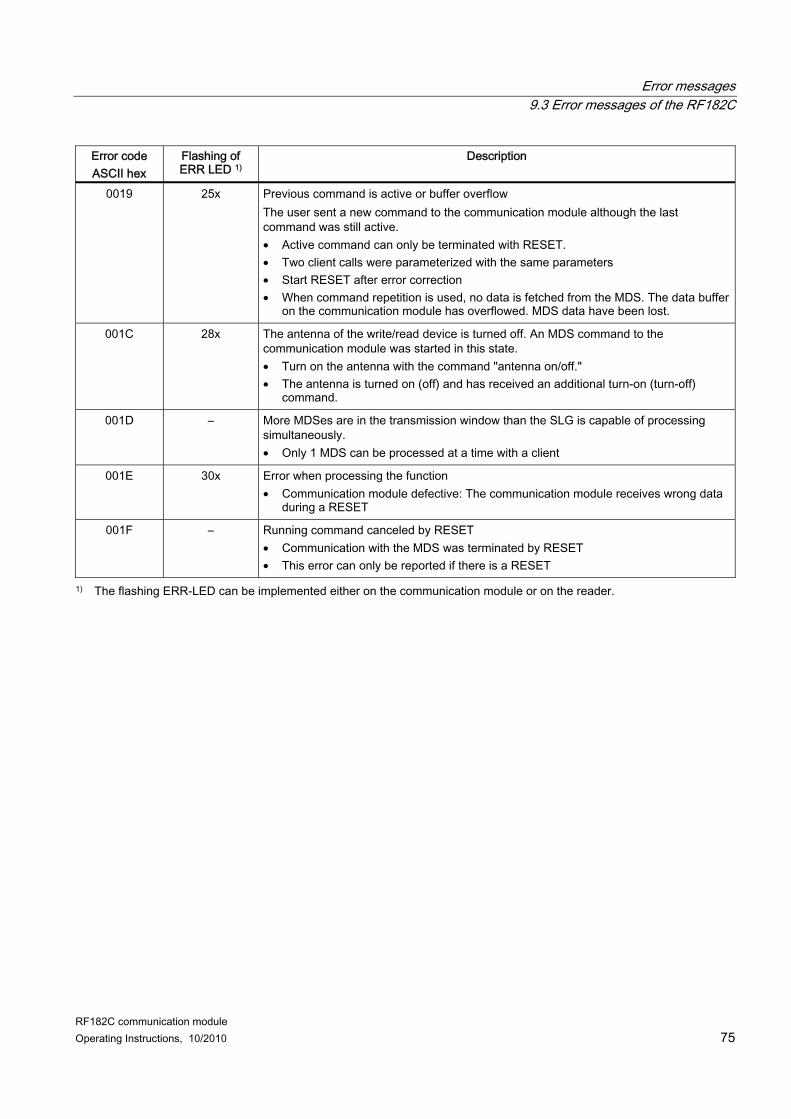
0019 25x Previous command is active or buffer overflow The user sent a new command to the communication module although the last command was still active. • Active command can only be terminated with RESET. • Two client calls were parameterized with the same parameters • Start RESET after error correction • When command repetition is used, no data is fetched from the MDS. The data buffer
on the communication module has overflowed. MDS data have been lost.
001C 28x The antenna of the write/read device is turned off. An MDS command to the communication module was started in this state. • Turn on the antenna with the command "antenna on/off." • The antenna is turned on (off) and has received an additional turn-on (turn-off)
command.
001D – More MDSes are in the transmission window than the SLG is capable of processing simultaneously. • Only 1 MDS can be processed at a time with a client
001E 30x Error when processing the function • Communication module defective: The communication module receives wrong data
during a RESET
001F – Running command canceled by RESET • Communication with the MDS was terminated by RESET • This error can only be reported if there is a RESET
1) The flashing ERR-LED can be implemented either on the communication module or on the reader.
Error messages 9.3 Error messages of the RF182C
RF182C communication module 76 Operating Instructions, 10/2010
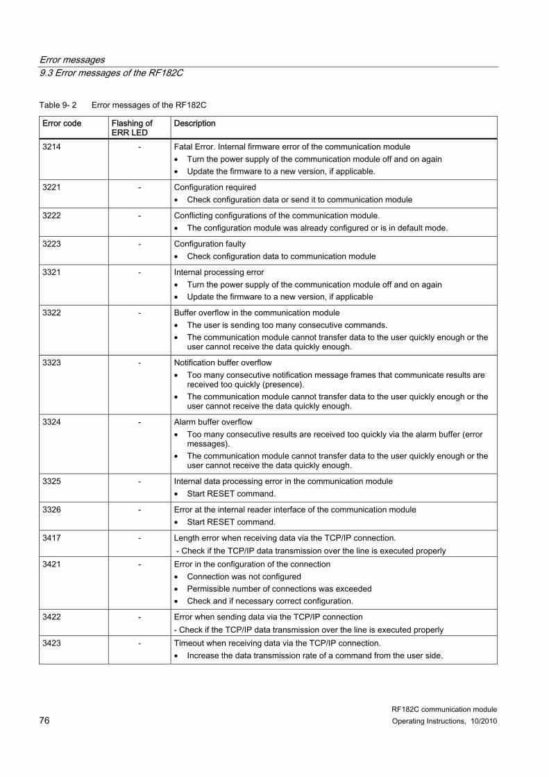
Table 9- 2 Error messages of the RF182C
Error code Flashing of ERR LED
Description
3214 - Fatal Error. Internal firmware error of the communication module • Turn the power supply of the communication module off and on again • Update the firmware to a new version, if applicable.
3221 - Configuration required • Check configuration data or send it to communication module
3222 - Conflicting configurations of the communication module. • The configuration module was already configured or is in default mode.
3223 - Configuration faulty • Check configuration data to communication module
3321 - Internal processing error • Turn the power supply of the communication module off and on again • Update the firmware to a new version, if applicable
3322 - Buffer overflow in the communication module • The user is sending too many consecutive commands. • The communication module cannot transfer data to the user quickly enough or the
user cannot receive the data quickly enough.
3323 - Notification buffer overflow • Too many consecutive notification message frames that communicate results are
received too quickly (presence). • The communication module cannot transfer data to the user quickly enough or the
user cannot receive the data quickly enough.
3324 - Alarm buffer overflow • Too many consecutive results are received too quickly via the alarm buffer (error
messages). • The communication module cannot transfer data to the user quickly enough or the
user cannot receive the data quickly enough.
3325 - Internal data processing error in the communication module • Start RESET command.
3326 - Error at the internal reader interface of the communication module • Start RESET command.
3417 - Length error when receiving data via the TCP/IP connection. - Check if the TCP/IP data transmission over the line is executed properly
3421 - Error in the configuration of the connection • Connection was not configured • Permissible number of connections was exceeded • Check and if necessary correct configuration.
3422 - Error when sending data via the TCP/IP connection - Check if the TCP/IP data transmission over the line is executed properly
3423 - Timeout when receiving data via the TCP/IP connection. • Increase the data transmission rate of a command from the user side.
Error messages 9.3 Error messages of the RF182C
RF182C communication module Operating Instructions, 10/2010 77
Error code Flashing of ERR LED
Description
3424 - Error when receiving the TCP channel • Connection was aborted • TCP/IP protocol error • Permissible number of connections at one port was exceeded • Check socket programming on the user side or find the fault with network analyzer
(Wireshark).
3425 - Receiving buffer overflow • Previous command is still active • Check if maximum possible number of commands was exceeded.
3521 - Incorrect UID • The length of the UID is not correct • A UID is required that has not been transferred by the user • Check UID
3523 - Conversion error • Check if individual characters of the user data of a command exceed the
permissible range for ASCII hex. (Range 0 – 9 or A – F ). The number of characters must be an even number.
3550 - Error in the XML structure of a command message frame. • Check command structure
Note Error handling procedure If error messages occur, execute a reset command to eliminate the error. If this procedure does not eliminate the error, disconnect the module from the power supply.
Error messages 9.4 Diagnostics via Web server
RF182C communication module 78 Operating Instructions, 10/2010
9.4 Diagnostics via Web server
9.4.1 Saving/reading of I&M data records Via Identification&Maintenance data records you can store internal information on the module and retrieve it as required.
Save data records Via the "Identification" menu in the "Settings" tab, various settings can be made and stored on the communication module. Use the "transmit and save" button to save the settings.
Error messages 9.4 Diagnostics via Web server
RF182C communication module Operating Instructions, 10/2010 79
Read data records To read out the data records from the communication module, switch to the "Identification" menu in the "Readout" tab.
9.4.2 Communication status query You can query the communication status of the RF182C communication module via the menu "Communication" in the Connection "tab". You can see the status of the user connection.
Error messages 9.4 Diagnostics via Web server
RF182C communication module 80 Operating Instructions, 10/2010
9.4.3 Event and message frame overview
Event overview Via the "Diagnostic" menu in the "Events " tab, you can query the events of the module.
Message frame overview Via the "Diagnostic" menu in the "Traffic " tab, you can query the last twenty message frames of the communication module.
RF182C communication module Operating Instructions, 10/2010 81
Examples/applications 1010.1 Basic principles of socket programming, exemplary in C
10.1.1 Socket programming requirements
Definition A socket is the end point of a communication connection. All modern operating systems nowadays have a socket application interface. This software interface permits access to the TCP/IP stack on the operating system used.
Requirements ● An operating system/programming language must be used that supports network
programs with sockets. ● Sockets are supported by the following operating systems: Microsoft Windows
95/98/ME/2000/XP/Vista, Linux, Unix. Other operating systems must be considered with regard to the usability of network programs.
● Sockets are used by many programming languages (e.g. C, C++, C#, Delphi, VB, Java). Other programming languages must be considered with regard to the usability of network programs.
Examples/applications 10.1 Basic principles of socket programming, exemplary in C
RF182C communication module 82 Operating Instructions, 10/2010
10.1.2 Basic client/server principle
Figure 10-1 Basic client/server principle
10.1.3 Important basic commands Commands/functions Description Socket() Initialization and parameter transfer of a new socket Bind() Assignment of a user (IP address and port number) to a socket Lists() Ready to connect Connect() Function for connecting the client to the server via TCP/IP Accept() Wait function of server until a client connects Send() Sending data Recv() Receiving data Close() Closing the socket after completing data transmission.
When working with the RF182C, a Close usually only occurs when the system is shut down.
Note No parameters or return values of the individual functions are listed here since they may differ in the different operating systems/programming languages. The names of the functions are examples only, they may differ in the operating systems/programming languages. These function examples are limited to the basic principles of the client/server representation – only a partial example of the functions is shown.
Examples/applications 10.1 Basic principles of socket programming, exemplary in C
RF182C communication module Operating Instructions, 10/2010 83
10.1.4 Partial programming example of a client in C/Windows operating system Under Windows, the header file "winsock.h" or the library "wsock32.lib" must also be integrated. These must be initialized before calling the Windows sockets.
Examples/applications 10.2 RF182C user application
RF182C communication module Operating Instructions, 10/2010 85
10.2 RF182C user application To permit user-friendly operation, there is an application available for the PC. The application is created in C# and can run direct on any Windows PC. You can load, modify, and expand the PC in your development environment. This application can be used as a basis for your application. You can find the application on the RFID CD "Software&Documentation", Edition 2009 or later. On the user interface, follow the link "CM/ASM > RF182C > Demo". You can start the program directly.
Requirements ● Operating system: Windows XP ● Development environment: Microsoft Visual Studio 2008
Procedure The application can be started direct via the user interface of the CD. The sources of the application are stored in a zip file on the CD. You will find the file under "Data/Tools > Applications/RF182C".
Functions This application offers the following functions: ● Establish connection ● Disconnect ● Notes on connection ● Input window for entering the commands ● Transfer of the commands to the RF182C communication module ● Display window for monitoring the communication process of the RF182C
(acknowledgements and error messages)
Examples/applications 10.2 RF182C user application
RF182C communication module 86 Operating Instructions, 10/2010
10.2.1 User interface layout
① IP address input window ② Port number input window ③ Button for connecting or disconnecting ④ Note: Connected or not connected ⑤ Note: Presence or no presence ⑥ Check box: The output window scrolls automatically or does not scroll automatically ⑦ Output window for receive data ⑧ Button for sending data in the input window Figure 10-2 User interface
Examples/applications 10.2 RF182C user application
RF182C communication module Operating Instructions, 10/2010 87
10.2.2 Extracts example code of the user application in C# using System;
using System.Collections.Generic;
using System.ComponentModel;
using System.Data;
using System.Drawing;
using System.Text;
using System.Windows.Forms;
using System.Net;
using System.Net.Sockets;
using System.Web;
namespace RF182CApp
public partial class MainForm : Format
{
// Socket to realize TCP/IP connection
private Socket Connection = null;
// connected (true) or not (false)
private bool ConnectionState = false;
// buffer for received data
private String ReceiveBuffer = "";
// Indicator for an error in asynchronous receive threads
bool AsyncError = false;
public MainForm()
{
InitializeComponent();
}
/* This routine is called when the window in initialized. */
Examples/applications 10.2 RF182C user application
RF182C communication module 94 Operating Instructions, 10/2010
{
switch (state)
{
case TagDetectionState.YES:
labelTagDetected.Text = "TAG(s) DETECTED";
labelTagDetected.BackColor = Color.Green;
break;
case TagDetectionState.NO:
labelTagDetected.Text = "NO TAG DETECTED";
labelTagDetected.BackColor = Color.Red;
break;
case TagDetectionState.UNDEFINED:
labelTagDetected.Text = "";
labelTagDetected.BackColor = BackColor; //Color of the dialog
break;
}
}
}
/* As long as no tag presence notification was send, we have no
* information whether there is a tag in the field or not.
* --> three states
* */
enum TagDetectionState
{
YES, NO, UNDEFINED
}
// This class is for handling asynchronous communication processes
internal class ReceiveString
{
public read-only static int BufferSize = 512;
public byte[] buffer = new byte[BufferSize];
}
// This class describes a XML block in ReceiveBuffer
internal class XMLTag
{
//Index of first character
public int startIndex;
//Block length
public int length;
// Type ( reply, notification or alarm, since only telegrams
// from the ASM are handled within this structure)
public String type;
}
}
Examples/applications 10.2 RF182C user application
RF182C communication module Operating Instructions, 10/2010 95
10.2.3 Functions of the RF182C applications The following screenshots show the different functions of the RF182C application:
Example of working with the application 1. First enter the IP address and port number in the corresponding entry fields.
Figure 10-3 RF182C not connected
Examples/applications 10.2 RF182C user application
RF182C communication module 96 Operating Instructions, 10/2010
2. Then click "Connect".
Figure 10-4 Connected successfully
The connection to the RF182C has been established successfully. The send window is empty after sending successfully.
Examples/applications 10.2 RF182C user application
RF182C communication module Operating Instructions, 10/2010 97
3. Enter a RESET command in the input window. Click the "Send" button.
Figure 10-5 RESET command
The RF182C communication module operates in default mode.
Examples/applications 10.2 RF182C user application
RF182C communication module 98 Operating Instructions, 10/2010
4. The next window shows that the RESET command has been sent successfully. The RF182C has sent an acknowledgement with the error code "0000" (everything OK). It is indicated that a tag has been detected in the antenna field of the reader (0001).
Figure 10-6 Tag detected
Examples/applications 10.3 Example application for a PLC according to DIN IEC 61131
RF182C communication module Operating Instructions, 10/2010 99
5. The next window shows that the tag has exited the reader's antenna field again (0000)
Figure 10-7 Tag exited the field
10.3 Example application for a PLC according to DIN IEC 61131 In preparation.
Examples/applications 10.3 Example application for a PLC according to DIN IEC 61131
RF182C communication module 100 Operating Instructions, 10/2010
RF182C communication module Operating Instructions, 10/2010 101
Technical data 11
Table 11- 1 General technical data
Ethernet interface to the user Principle Ethernet Physical medium Ethernet (TCP/IP communication) Duty type • 10BASE-T Full or Half Duplex
• 100BASE-TX Fast Ethernet Full or Half Duplex
Transmission rate 10/100 Mbit/s Plug-in connection M12, 4-pin, D coding Maximum cable length 100 m Cable type STP Cat 5 Autonegotiation Yes Autocrossing Yes Switch function Yes, internal Serial interface to the reader/SLG Connector 2 x M12 coupler plugs, 8-pin Max. cable length 1000 m, dependent on Reader/SLG
(2 m = standard length; for other standard cables and self-assembled cables, refer to Section Connection cables)
Connectable readers/SLGs 2x readers/SLG of the RFID families RF300, RF600, MOBY D/U
Software functions Tag/MDS addressing Direct access via addresses Commands Initialize tag, read data from tag, write data to tag, etc. Supply voltage1) Rated value 24 V DC Permissible range 20 V to 30 V DC Current consumption without reader / SLG 2)
max. 500 mA; typ. 100 mA
Current consumption through reader connection
Each 500 mA
Maximum infeed current in the connection block M12, 7/8''
1L = 6 A 2L = 8 A
Maximum infeed current in the push-pull connection block
Up to 40 °C: 1L = 12 A 3) 2L = 12 A
Up to 60 °C: 1L = 8 A 2L = 8 A
Galvanic isolation Yes
Technical data
RF182C communication module 102 Operating Instructions, 10/2010
Ambient temperature During operation 0 to +60 °C Transport and storage –40 to +70 °C Dimensions (W x H x D) in mm Base unit only 60 x 210 x 30 Base unit with connection block M12, 7/8''
60 x 210 x 54
Base unit with push-pull connection block
60 x 216 x 100
Weight Base unit Approx. 210 g Connection block M12, 7/8'' Approx. 230 g Push-pull connection block Approx. 120 g Mechanical Environmental Conditions Mounting position All mounting positions are possible Vibration during operation According to IEC 61131-2:
0.75 mm (10Hz to 58 Hz) 10 g (58 Hz to 150 Hz)
Shock resistance, shock during operation
Acc. to IEC 61131-2: 30 g
Degree of protection IP67 MTBF (Mean Time Between Failures) in years Base unit 121 Connection block 1100 Approvals cULus (file E116536)
FCC Code of Federal Regulations, CFR 47, Part 15, Sections 15.107 and 15.109 (Class A)
1) All supply and signal voltages must be safety extra low voltage (SELV/PELV according to EN 60950) 24 V DC supply: Safety (electrical) isolation of low voltage (SELV / PELV acc. to EN 60950)
2) The power supply must provide the current required (max. 500 mA) during brief power failures of ≤ 20 ms.
3) A cable cross-section of 2.5 mm² is mandatory for an amperage > 8 A.
RF182C communication module Operating Instructions, 10/2010 103
Dimension drawings 1212.1 Dimension drawing for RF182C with fixing holes
Dimension drawing of an RF182C with bus connection block M12, 7/8'' PN PN
Figure 12-1 Dimension drawing of an RF182C with bus connection block M12, 7/8''
Dimension drawings 12.1 Dimension drawing for RF182C with fixing holes
RF182C communication module 104 Operating Instructions, 10/2010
Dimension drawing of an RF182C with push-pull bus connection block
Figure 12-2 Dimension drawing of an RF182C with push-pull bus connection block
RF182C communication module Operating Instructions, 10/2010 105
Connecting cable to the reader/SLG 1313.1 Routing of standard cables
Available cables
Figure 13-1 Connecting cable, M12 ↔ Reader / SLG; l = 2 m, 5 m (MOBY U)
Figure 13-2 Connecting cable/extension cable M12 ↔ M12; l = 2 m, 5 m, 10 m, 20 m, 50 m
● Connecting cable RF300/RF600; MOBY D only 6GT2602-0AB10-0AX0 ● Extension cable for all RFID systems
Figure 13-3 Connecting cable M12 ↔ sub-D (MOBY D all SLGs except 6GT2602-0AB10-0AX0)
Maximum cable length The RF182C can be operated with any reader/SLG configuration with a maximum cable length of 50 m. Longer connecting cables of up to 1000 m are possible in some instances. The current consumption of the connected reader/SLG must however be taken into account. You will find information in the relevant system manuals. Sequential arrangement of more than two sub-sections to form a long section of cable should be avoided due to the additional contact resistances.
Connecting cable to the reader/SLG 13.1 Routing of standard cables
RF182C communication module 106 Operating Instructions, 10/2010
Note: Reader/SLG with Sub-D connector must be supplied over an additional connector with 24 V DC.
Connecting cable to the reader/SLG 13.2 Self-assembled cable
RF182C communication module Operating Instructions, 10/2010 107
13.2 Self-assembled cable A reader/SLG connector plug with screw terminals is provided for users who want to individually pre-assemble their own cables (refer to the relevant system manual). Cables and reader/SLG connector plugs can be ordered from the Catalog FS 10 Sensors for Production Automation.
Cable structure You will need cables of the following specifications for self-assembled cables: 7 x 0.25 mm2 LiYC11Y 7 x 0.25
Connectors M12 connectors can be obtained from the relevant specialist dealers (e.g. Binder).
Pin assignment The pin assignment is listed in the following table.
Table 13- 4 Pin assignment
M12 connector (male) Pin Signal Core color 1 1L+ (+ 24 V) 2 −RxD 3 0 V 4 RxD 5 TxD 6 −TxD 7 Free
8 Functional ground (PE)/shield
Note data sheet provided by cable manufacturer
Connecting cable to the reader/SLG 13.2 Self-assembled cable
RF182C communication module 108 Operating Instructions, 10/2010
RF182C communication module Operating Instructions, 10/2010 109
Ordering data 14
Table 14- 1 RF182C ordering data and accessories
RF182C RF182C communication module max. 2 SLGs or readers can be connected
6GT2002-0JD10
Connection block M12, 7/8'' (5-pole) 6GT2002-1JD00 Connection block M12, 7/8'' (4-pole) 6GT2002-4JD00 Push-pull connection block, RJ45 6GT2002-2JD00 Labels 20 x 7 mm (1 pack = 340 items) 3RT1900-1SB20 Accessories for connection block M12, 7/8" (5-pole) IE plug-in cable for PROFINET/Ethernet (pre-assembled trailing cable with two M12 connectors, 4-pin, code D)
6XV1870-8Axxx 1)
7/8"-plug-in cable for supply voltage (5 x 1.5 mm2) (pre-assembled trailing power cable with two 5-pin 7/8" connectors)
6XV1822-5Bxxx 1)
Trailing power cable (5 x 1.5 mm2) (not pre-assembled; length min. 20 m, length max. 1000 m)
6XV1830-8AH10
Connector plug 7/8" for supply voltage; (1 pack = 5 items) • with pin insert • with socket insert
6GK1905-0FA00 6GK1905-0FB00
RJ45 plug-in cable with metal casing and FC connection system, 180 ° cable outlet;(1 pack = 1 item)
6GK1901-1BB10-2AA0
Control cabinet feedthrough for conversion from M12 connection method (D coded, IP65) to RJ45 connection method (IP20) ;(1 pack = 5 items)
6GK1901-0DM20-2AA5
M12 plug-in cable with metal casing and fast connection system, 180 ° cable outlet (D coded) ; (1 pack = 1 item)
6GK1901-0DB10-6AA0
M12 covering caps 3RX9802-0AA00 Covering caps 7/8" (1 pack = 10 items) 6ES7194-3JA00-0AA0 PROFINET/Ethernet standard cable 2x2, Type A, unassembled; minimum order quantity 20 m
6XV1840-2AH10
Accessories for connection block M12, 7/8" (4-pole) Cable for supply voltage pre-assembled with 7/8’’ 4-pole connectors (only for 6GT2002-4JD00)
Not available from Siemens
Ordering data
RF182C communication module 110 Operating Instructions, 10/2010
Accessories for push-pull connection block Trailing power cable (5 x 1.5 mm2) (not pre-assembled; length min. 20 m, length max. 1000 m)
6XV1830-8AH10
Push-pull cable connector for 1L+/2L+, not pre-assembled 6GK1907-0AB10-6AA0 Push-pull cable connector for RJ45, not pre-assembled 6GK1901-1BB10-6AA0 Caps for push-pull sockets (1L+/2L+), 5 items per package, 1 item 6ES7194-4JA50-0AA0 Caps for push-pull sockets RJ45, 5 items per package, 1 item 6ES7194-4JD50-0AA0 PROFINET/Ethernet standard cable 2x2, Type A, unassembled; minimum order quantity 20 m
6XV1840-2AH10
Accessories for RFID SLG cable MOBY U; 2 m 6GT2091-0FH20 SLG cable MOBY U; 5 m 6GT2091-0FH50 SLG cable MOBY D; 2 m 6GT2691-0FH20 Reader cable RF300, extension cable RF300 / RF600 / MOBY I / E / U / D; 2 m
6GT2891-0FH20
Reader cable RF300, extension cable RF300 / RF600 / MOBY U / D; 5 m
6GT2891-0FH50
Reader cable RF300, extension cable RF300 / RF600 / MOBY U / D; 10 m
6GT2891-0FN10
Reader cable RF300, extension cable RF300 / RF600 / MOBY U / D; 20 m
6GT2891-0FN20
Reader cable RF300, extension cable RF300 / RF600 / MOBY U / D; 50 m
6GT2891-0FN50
Reader cable for RF300; connector on the reader is angled; 2 m 6GT2891-0JH20 RFID CD "Software&Documentation" 6GT2080-2AA10
1) These cables are available in different lengths. See Catalog IK PI for more details
RF182C communication module Operating Instructions, 10/2010 111
Command and acknowledgement telegrams A
In this Section, you will find detailed information on some commands mentioned in Section Communication interface (Page 49). Only those commands requiring a special coding of commands and results are described.
Note Special information on telegram expansions for the RF620R/RF630R readers can be found in the Appendix of the "Configuration Manual RF620R/RF630R".
Command and acknowledgement telegrams
RF182C communication module 112 Operating Instructions, 10/2010
RESET
Command and acknowledgement telegrams
RF182C communication module Operating Instructions, 10/2010 113
Byte 18 19 20 21 22 23 24 25 26 27 Param res dili multi fcon fon sync ant stand_
by MDS control
Parameter name Comment S-Info Reader status mode information = 01 HW Hardware type HW-V Hardware version LD-V Version of loader FW Firmware type FW-V Firmware version TR Driver type TR-V Version of driver INT Interface (RS 232/RS 422) Baud Baud rate Dili Range-capacity setting multi Multitag reader fcon field_ON_control: BERO mode
(RF300: res) fon Field_on_time:
• MOBY U: BERO time • MOBY D: Tag type • RF300-ISO: Tag type
sync Semaphore control (synchronization with reader (RF300: res)
ant Status of antenna stand_by Time of standby after command execution
(RF300: res) MDS control Presence mode
For detailed information, please refer to the respective reader description.
Command and acknowledgement telegrams
RF182C communication module 114 Operating Instructions, 10/2010
GetReaderStatus mode = 02
GetReaderStatus mode = 03
GetReaderStatus mode = 04
GetReaderStatus mode = 05
Command and acknowledgement telegrams
RF182C communication module Operating Instructions, 10/2010 115
Parameter name Comment S-Info Reader status mode information = 07 HW Hardware type HW-V Hardware version res0 Reserved FW Firmware type FW-V Firmware version TR Driver type H hours Min. Minutes Sec Seconds res1 Reserved SLG-V Reader version Baud Baud rate res2 Reserved dili_SLG Set transmission performance multi Multitag reader field_on_control Set communication type field_on_time Set channel expert Expert mode ant Status of antenna scanning_time Radio communication profile MDS control Presence mode
For detailed information, please refer to the respective reader description.
Command and acknowledgement telegrams
RF182C communication module Operating Instructions, 10/2010 117
Parameter name Comment UID UID (tag number, EPC ID) MDS_type MDS type sum_sub Sum of subframe access sum_search Sum of searchmode week Date of last sleep-time change (week of year) Year Date of last sleep-time change (year) battery Battery left (percentage) ST Set sleep-time value on MDS
For detailed information, please refer to the respective reader description.
Command and acknowledgement telegrams
RF182C communication module 118 Operating Instructions, 10/2010
Parameter name Comment status Tag status mode information = 02 UID 1 4 UID (tag number) UID 5 8 always 0 IC_version Chip version (for my-d = 00h) Size Memory size in bytes lock_state Lock status, OTP information: per block
(4x4 bytes or 2x8 bytes) one bit (bit=1: block is locked)
block_size Block size of the transponder nr_of_blocks Number of blocks
For detailed information, please refer to the respective reader description.
Command and acknowledgement telegrams
RF182C communication module Operating Instructions, 10/2010 121
GetTagStatus mode = 04
Byte 0 1 2 3 4 5 6 7 8 9 10 11 12 13 14 15 16 Param status UID 1 4 UID 5 8 ant RSSI H Min. Sec res res1 res2
Parameter name Comment status Tag status mode information = 04 UID 1 4 UID 5 8
UID (tag number, EPC ID)
ant Antenna that has detected the MDS RSSI RSSI threshold value H hours Min. Minutes Sec Seconds res Spare res1 Spare res2 Spare
For detailed information, please refer to the respective reader description.
Command and acknowledgement telegrams
RF182C communication module 122 Operating Instructions, 10/2010
RF182C communication module Operating Instructions, 10/2010 123
Addressing of the RFID tags B
Address space of the MDS versions for MOBY U
Table B- 1 Address space MOBY U
Memory Addressing 16-bit hexadecimal number Integer number Start address End address
0000 07FF
+0 +2047
Memory size 08 00 2048 Read OTP memory (write access only possible once. The OTP memory of MOBY U can only be processed completely, i.e. the start address must always be specified with value FFF0 hex and the length with value 10 hex.) Start address Length
FFF0 10
-16 +16
2 KB data
memory
ID No.: (4 fixed-coded bytes; can only be read with the MDS status command) Start address End address
0000 7FFF
+0 +32767
Memory size 80 00 32768 Read OTP memory (write access only possible once)* Start address Length
FFF0 10
-16 +16
32 KB data memory
ID No.: (4 fixed-coded bytes; can only be read with the MDS status command)
Address space of the MDS versions for MOBY D For address space of the RF300 transponders, see MOBY D System Manual (http://support.automation.siemens.com/WW/view/en/13628689/0/en), section "Mobile data storage units > Introduction".
Address space of the transponder versions for RF300 For address space of the RF300 transponders, see SIMATIC RF300 System Manual (http://support.automation.siemens.com/WW/view/en/21738946/0/en), section "RF300 transponders > Memory configuration of the RF300 tags" and section "ISO transponders > Memory configuration of the ISO tags".
RF182C communication module 124 Operating Instructions, 10/2010
Address space of the transponder versions for RF600 For address space of the RF600 transponders, see SIMATIC RF620R/RF630R Parameterization Manual (http://support.automation.siemens.com/WW/view/de/33287195/0/en), section "Examples/applications > Memory configuration".
RF182C communication module Operating Instructions, 10/2010 125
Transfer scheme for hexadecimal tag data via XML C
The addresses for memory addressing on the tag are hexadecimal. The data on the tag is also stored in hexadecimal format. However, with the read/write commands, the data is transferred as ASCII characters. Conversion from hex to ASCII hex and vice versa is executed automatically in the communication module. The following example shows the coding scheme:
Command to RF182C <readTagData> <startAddress>0000</startAddress> <dataLength>0004</dataLength> </readTagData>
Data in tag
Address [hex]
Data [hex]
Data [ADC]
0000 4D 'M' 0001 4F 'O' 0002 42 'B' 0003 59 'Y'
...
Result of the RF182C <readTagData> <returnValue> <data>4D4F4259</data> </returnValue> </readTagDatat>
Transfer scheme for hexadecimal tag data via XML
RF182C communication module 126 Operating Instructions, 10/2010
Optional: storage of the result data in the data block of a controller
RF182C communication module Operating Instructions, 10/2010 127
Service & support D
Technical support The technical support specialists advise and assist customers by responding to their queries on the functions of our RFID products and how to work with them. You can reach us worldwide Mon. to Fri. during office hours: 8 a.m. - 5 p.m. CET: Telephone: ++49 (0) 180 5050-222 Fax: ++49 (0) 180 5050-223
Internet Visit our site on the Internet at: Support homepage (www.siemens.com/automation/service&support) You can send a support query to: Online support request form: (www.siemens.com/automation/support-request) General information on new features of the RF182C communication module and an overview of our other identification systems can be found on the Internet at: RFID homepage (www.siemens.com/simatic-sensors/rf)