1 Carlo Gavazzi Ltd. RGC_DS ENG 08/07/21 1-Phase Solid State Contactors, ‘E’- type connection Benefits • Panel space savings. The slimmest product in the range accomodates up to 37 AAC in a width of only 17.5 mm giving 25% space saving per SSR compared to 22.5 mm solutions. • Less maintenance costs. Wire bonding technology reduces thermal and mechanical stresses of the output chips resulting in a larger number of operational cycles compared to other assembly technologies. • Low machine downtime. Integrated overvoltage protection prevents the solid state relay from breaking down due to uncontrolled transients that may occur on the lines. • Ease of use. The RGC ready-to-use solution is provided with integrated heatsink thus eliminating the need for the user to calculate the size of heatsink needed for adequate thermal dissipation. • Cost effective protection co-ordination. The high I²t specification permits easy Type 2 protection co-ordination with B-type Minitaure Circuit Breakers. • Fast wiring. Power connections for models rated ≥37 A are equipped with terminals that can handle cables up to 25 mm 2 / AWG3 cables. Spring loaded control terminals are also available that help reduce installation time. • Accommodates UL508A requirements for Industrial Control Panels. The RGC is certified as a listed product. All models carry a 100 kArms Short Circuit Current Rating. • Protection against SSR overheat. Optional feature with integrated over temperature protection protects the RGC output from getting damaged in case of overheating. This feature is present by default on the variants with integrated fan and optional on other variants. This slimline range of solid state contactors is an evolution of solid state switches for which Carlo Gavazzi is very well known. The RG solid state contactors present a unique opportunity for panel space savings thanks to their very slim footprint. The RGC is the ready-to-use range that is provided with an integrated heatsink. The smallest footprint occupies only a width of 17.5 mm with ratings up to 37 AAC. The power and control teminals allow for safe looping of cables. Spring- loaded pluggable control terminals are an option when faster installation time is required. The RGC output is protected against overvoltages by means of an integrated varistor. Control ON indication is provided through a green LED. Specifications are at a surrounding temperature of 25°C unless otherwise specified. RGC Applications Plastic injection machines, Extrusion machines, Blow moulding machines, Thermoformers, Dryers, Electrical ovens, Fryers, Shrink tunnels, Air handling units, Sterilisation equipment, Climatic chambers, Ovens and furnaces, Ambient heating. Main features • Ratings up to 660 VAC, 85 A @ T A 40°C • Up to 18000 A²s for I²t for protection coordination with M.C.Bs • 100kA short circuit current rating according to UL508 • Conformance to Railway standards Description
Transcript
1Carlo Gavazzi Ltd.
RGC
RGC_DS ENG 08/07/21
1-Phase Solid State Contactors, ‘E’- type connection
Benefits
• Panel space savings. The slimmest product in the range accomodates up to 37 AAC in a width of only 17.5 mm giving 25% space saving per SSR compared to 22.5 mm solutions.
• Less maintenance costs. Wire bonding technology reduces thermal and mechanical stresses of the output chips resulting in a larger number of operational cycles compared to other assembly technologies.
• Low machine downtime. Integrated overvoltage protection prevents the solid state relay from breaking down due to uncontrolled transients that may occur on the lines.
• Ease of use. The RGC ready-to-use solution is provided with integrated heatsink thus eliminating the need for the user to calculate the size of heatsink needed for adequate thermal dissipation.
• Cost effective protection co-ordination. The high I²t specification permits easy Type 2 protection co-ordination with B-type Minitaure Circuit Breakers.
• Fast wiring. Power connections for models rated ≥37 A are equipped with terminals that can handle cables up to 25 mm2 / AWG3 cables. Spring loaded control terminals are also available that help reduce installation time.
• Accommodates UL508A requirements for Industrial Control Panels. The RGC is certified as a listed product. All models carry a 100 kArms Short Circuit Current Rating.
• Protection against SSR overheat. Optional feature with integrated over temperature protection protects the RGC output from getting damaged in case of overheating. This feature is present by default on the variants with integrated fan and optional on other variants.
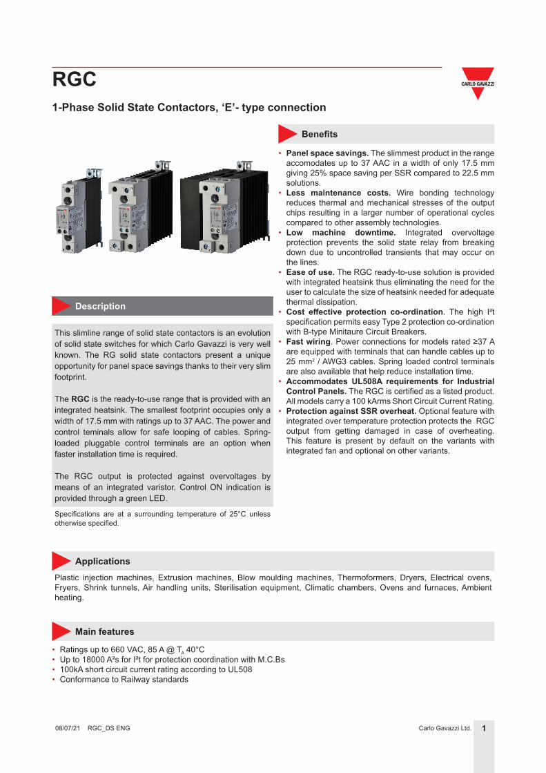
This slimline range of solid state contactors is an evolution of solid state switches for which Carlo Gavazzi is very well known. The RG solid state contactors present a unique opportunity for panel space savings thanks to their very slim footprint.
The RGC is the ready-to-use range that is provided with an integrated heatsink. The smallest footprint occupies only a width of 17.5 mm with ratings up to 37 AAC. The power and control teminals allow for safe looping of cables. Spring-loaded pluggable control terminals are an option when faster installation time is required.
The RGC output is protected against overvoltages by means of an integrated varistor. Control ON indication is provided through a green LED.
Specifications are at a surrounding temperature of 25°C unless otherwise specified.
• Ratings up to 660 VAC, 85 A @ TA 40°C• Up to 18000 A²s for I²t for protection coordination with M.C.Bs• 100kA short circuit current rating according to UL508• Conformance to Railway standards
Description
2Carlo Gavazzi Ltd.
RGC
RGC_DS ENG 08/07/21
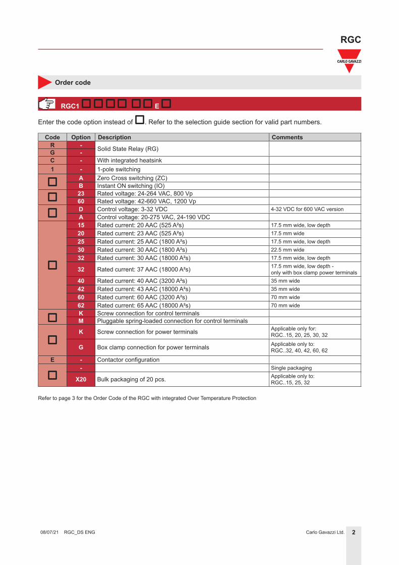
Enter the code option instead of . Refer to the selection guide section for valid part numbers.
Order code
RGC1 E
Code Option Description CommentsR - Solid State Relay (RG)G -C - With integrated heatsink1 - 1-pole switching
A Zero Cross switching (ZC)B Instant ON switching (IO)
23 Rated voltage: 24-264 VAC, 800 Vp60 Rated voltage: 42-660 VAC, 1200 VpD Control voltage: 3-32 VDC 4-32 VDC for 600 VAC versionA Control voltage: 20-275 VAC, 24-190 VDC15 Rated current: 20 AAC (525 A²s) 17.5 mm wide, low depth20 Rated current: 23 AAC (525 A²s) 17.5 mm wide25 Rated current: 25 AAC (1800 A²s) 17.5 mm wide, low depth30 Rated current: 30 AAC (1800 A²s) 22.5 mm wide32 Rated current: 30 AAC (18000 A²s) 17.5 mm wide, low depth
32 Rated current: 37 AAC (18000 A²s) 17.5 mm wide, low depth - only with box clamp power terminals
40 Rated current: 40 AAC (3200 A²s) 35 mm wide42 Rated current: 43 AAC (18000 A²s) 35 mm wide60 Rated current: 60 AAC (3200 A²s) 70 mm wide62 Rated current: 65 AAC (18000 A²s) 70 mm wideK Screw connection for control terminalsM Pluggable spring-loaded connection for control terminals
K Screw connection for power terminals Applicable only for: RGC..15, 20, 25, 30, 32
G Box clamp connection for power terminals Applicable only to:RGC..32, 40, 42, 60, 62
E - Contactor configuration- Single packaging
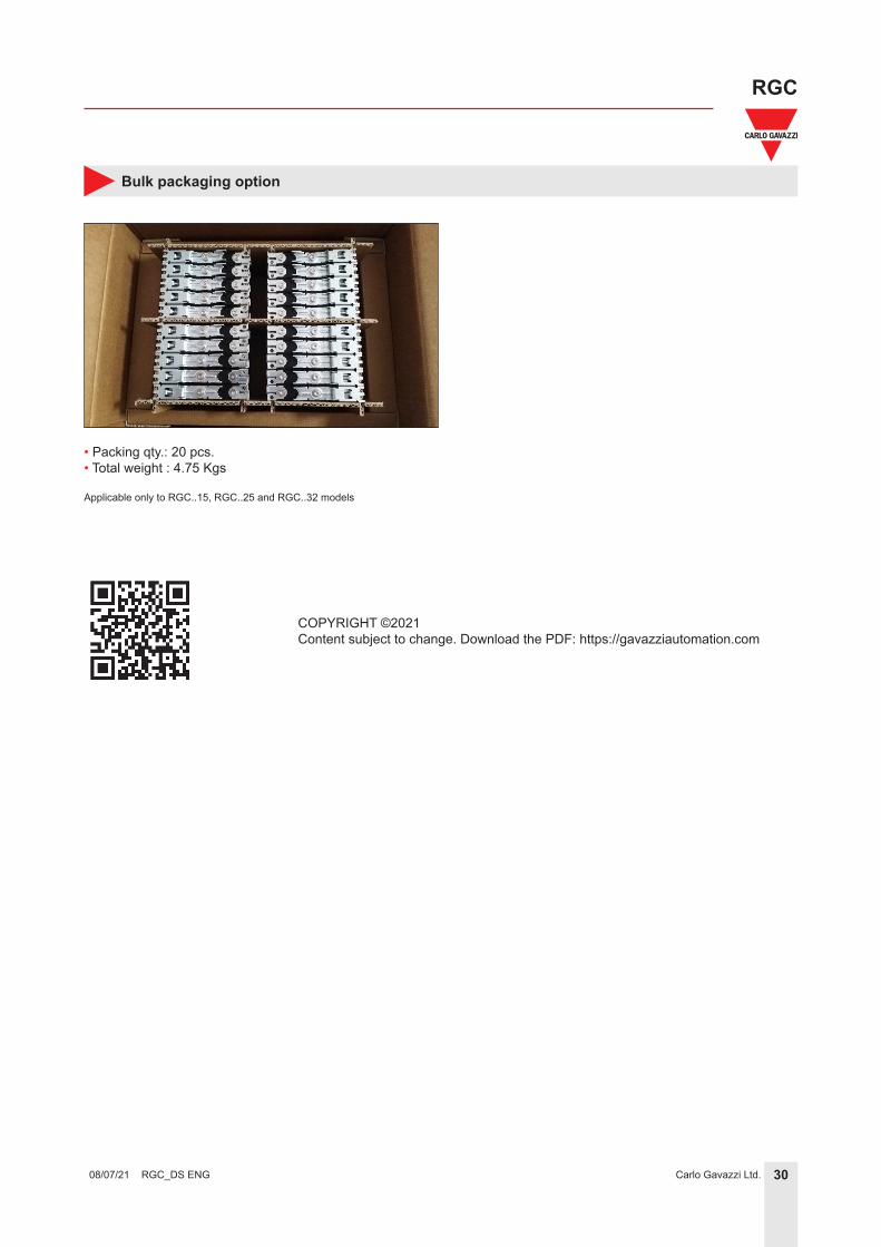
X20 Bulk packaging of 20 pcs. Applicable only to:RGC..15, 25, 32
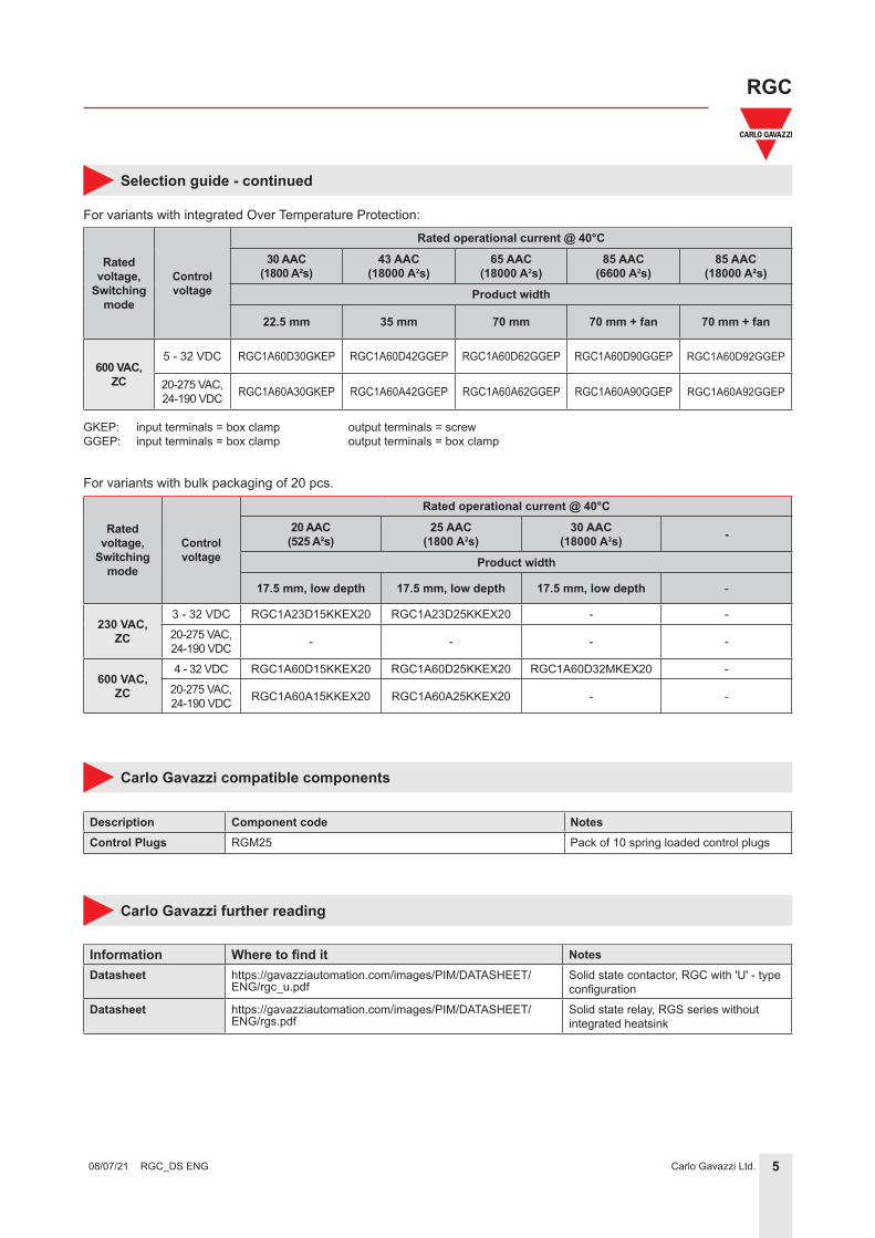
Refer to page 3 for the Order Code of the RGC with integrated Over Temperature Protection
3Carlo Gavazzi Ltd.
RGC
RGC_DS ENG 08/07/21
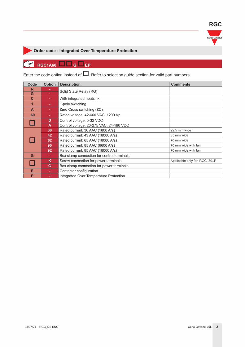
Code Option Description CommentsR - Solid State Relay (RG)G -C - With integrated heatsink1 - 1-pole switchingA - Zero Cross switching (ZC)
60 - Rated voltage: 42-660 VAC, 1200 VpD Control voltage: 5-32 VDCA Control voltage: 20-275 VAC, 24-190 VDC30 Rated current: 30 AAC (1800 A²s) 22.5 mm wide42 Rated current: 43 AAC (18000 A²s) 35 mm wide62 Rated current: 65 AAC (18000 A²s) 70 mm wide90 Rated current: 85 AAC (6600 A²s) 70 mm wide with fan92 Rated current: 85 AAC (18000 A²s) 70 mm wide with fan
G - Box clamp connection for control terminalsK Screw connection for power terminals Applicable only for: RGC..30..PG Box clamp connection for power terminals
E - Contactor configurationP - Integrated Over Temperature Protection
Enter the code option instead of . Refer to selection guide section for valid part numbers.
Order code - integrated Over Temperature Protection
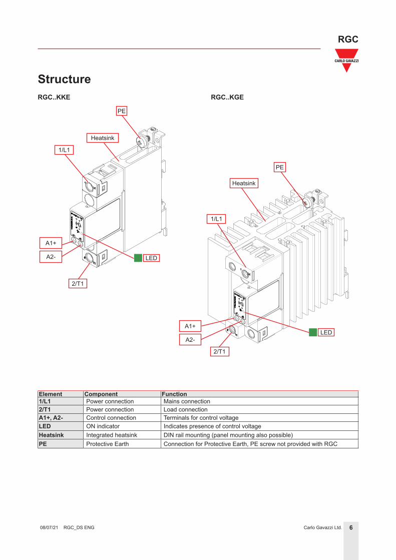
Element Component Function1/L1 Power connection Mains connection2/T1 Power connection Load connectionA1+, A2- Control connection Terminals for control voltageLED ON indicator Indicates presence of control voltage Heatsink Integrated heatsink DIN rail mounting (panel mounting also possible)PE Protective Earth Connection for Protective Earth, PE screw not provided with RGC
RGC..KGERGC..KKE
LED
A1+
Heatsink
1/L1
2/T1
PE
LED
PE
Heatsink
1/L1
2/T1
A2-
A1+
A2-
7Carlo Gavazzi Ltd.
RGC
RGC_DS ENG 08/07/21
RGC...D9xGGEP*RGC...30GKEP
LEDA1+
Heatsink
1/L1
2/T1
PE
LED
A2-
LED
LED
12-
11+
2/T1
Heatsink
1/L1
PE
A1+
A2-
IN1
OUT
IN3
IN2
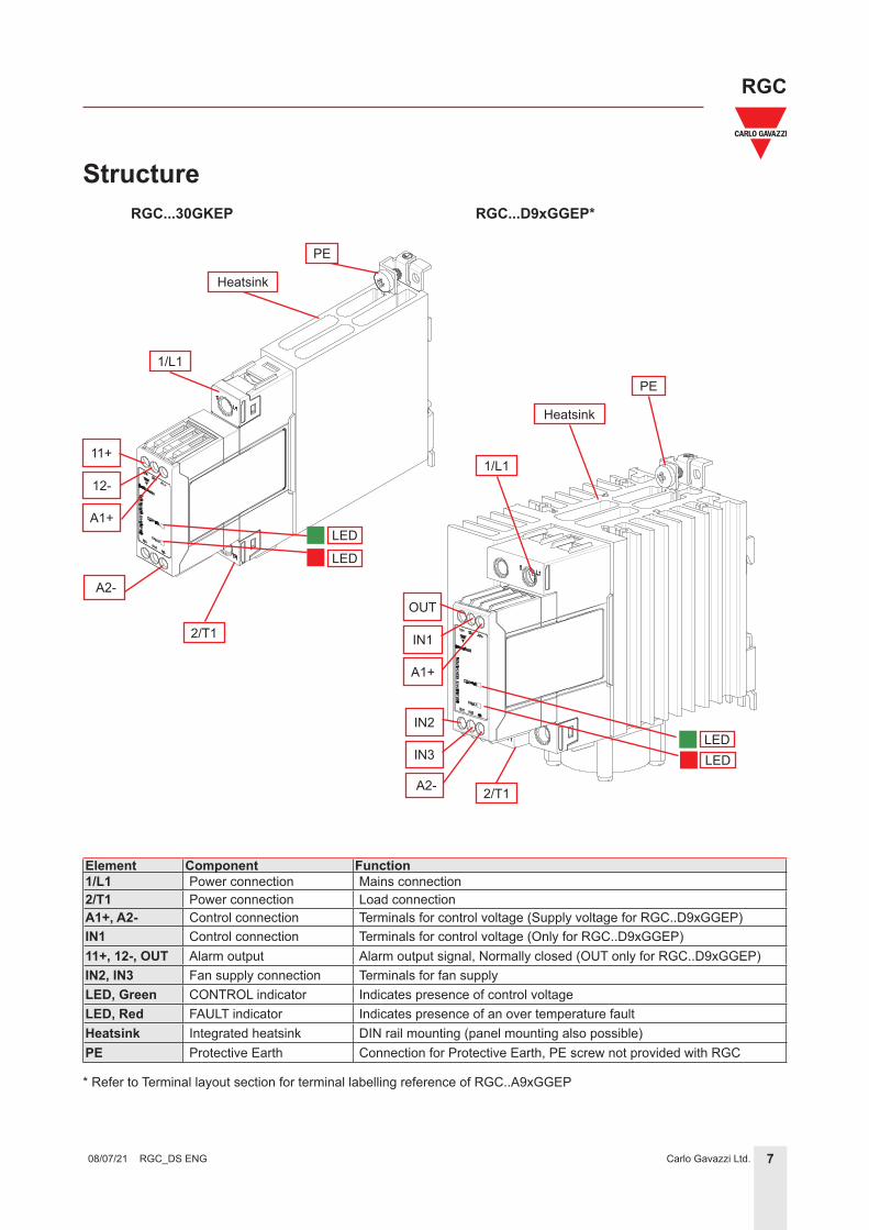
Structure
Element Component Function1/L1 Power connection Mains connection2/T1 Power connection Load connectionA1+, A2- Control connection Terminals for control voltage (Supply voltage for RGC..D9xGGEP)IN1 Control connection Terminals for control voltage (Only for RGC..D9xGGEP)11+, 12-, OUT Alarm output Alarm output signal, Normally closed (OUT only for RGC..D9xGGEP)IN2, IN3 Fan supply connection Terminals for fan supplyLED, Green CONTROL indicator Indicates presence of control voltageLED, Red FAULT indicator Indicates presence of an over temperature fault Heatsink Integrated heatsink DIN rail mounting (panel mounting also possible)PE Protective Earth Connection for Protective Earth, PE screw not provided with RGC
* Refer to Terminal layout section for terminal labelling reference of RGC..A9xGGEP
8Carlo Gavazzi Ltd.
RGC
RGC_DS ENG 08/07/21
Features
MaterialPA66 or PA6 (UL94 V0), RAL7035Glow wire ignition temperature and Glow wire flammability index conform to EN 60335-1 requirements
Mounting DIN rail (panel mount also possible)Touch Protection IP20Overvoltage Category III, 6 kV (1.2/50 μs) rated impulse withstand voltage
IsolationInput and Output to Case: Input to Output: Input to FAN/ Alarm Output:
4000 Vrms4000 Vrms, 2500 Vrms for RGC..D..P2500 Vrms applicable only to RGC..A..P
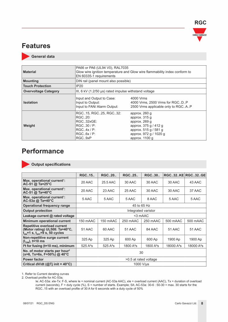
Operational frequency range 45 to 65 HzOutput protection Integrated varistorLeakage current @ rated voltage <3 mAACMinimum operational current 150 mAAC 150 mAAC 250 mAAC 250 mAAC 500 mAAC 500 mAACRepetitive overload current(Motor rating) UL508: Ta=40°C,tON=1 s, tOFF=9 s, 50 cycles
51 AAC 60 AAC 51 AAC 84 AAC 51 AAC 51 AAC
Non-repetitive surge current (ITSM), t=10 ms 325 Ap 325 Ap 600 Ap 600 Ap 1900 Ap 1900 Ap
I²t for fusing (t=10 ms), minimum 525 A²s 525 A²s 1800 A²s 1800 A²s 18000 A²s 18000 A²sNo. of motor starts per hour2
(x=6, Tx=6s, F=50%) @ 40°C 30
Power factor >0.5 at rated voltageCritical dV/dt (@Tj init = 40°C) 1000 V/μs
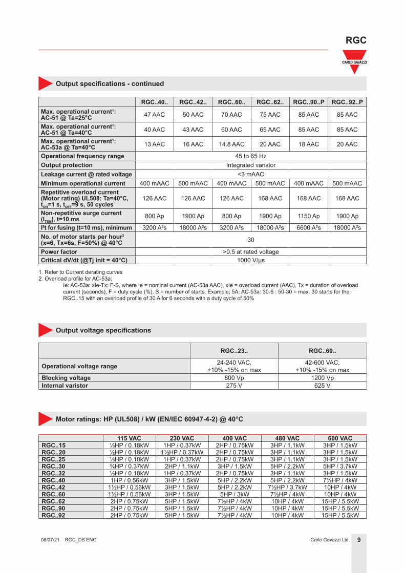
Output specifications
1. Refer to Current derating curves 2. Overload profile for AC-53a; Ie: AC-53a: xIe-Tx: F-S, where Ie = nominal current (AC-53a AAC), xIe = overload current (AAC), Tx = duration of overload current (seconds), F = duty cycle (%), S = number of starts. Example; 5A: AC-53a: 30-6 : 50-30 = max. 30 starts for the RGC..15 with an overload profile of 30 A for 6 seconds with a duty cycle of 50%
Operational frequency range 45 to 65 HzOutput protection Integrated varistorLeakage current @ rated voltage <3 mAACMinimum operational current 400 mAAC 500 mAAC 400 mAAC 500 mAAC 400 mAAC 500 mAACRepetitive overload current(Motor rating) UL508: Ta=40°C,tON=1 s, tOFF=9 s, 50 cycles
126 AAC 126 AAC 126 AAC 168 AAC 168 AAC 168 AAC
Non-repetitive surge current (ITSM), t=10 ms 800 Ap 1900 Ap 800 Ap 1900 Ap 1150 Ap 1900 Ap
I²t for fusing (t=10 ms), minimum 3200 A²s 18000 A²s 3200 A²s 18000 A²s 6600 A²s 18000 A²sNo. of motor starts per hour2
(x=6, Tx=6s, F=50%) @ 40°C 30
Power factor >0.5 at rated voltageCritical dV/dt (@Tj init = 40°C) 1000 V/μs
RGC..23.. RGC..60..
Operational voltage range 24-240 VAC,+10% -15% on max
42-600 VAC,+10% -15% on max
Blocking voltage 800 Vp 1200 VpInternal varistor 275 V 625 V
Output voltage specifications
1. Refer to Current derating curves 2. Overload profile for AC-53a; Ie: AC-53a: xIe-Tx: F-S, where Ie = nominal current (AC-53a AAC), xIe = overload current (AAC), Tx = duration of overload current (seconds), F = duty cycle (%), S = number of starts. Example; 5A: AC-53a: 30-6 : 50-30 = max. 30 starts for the RGC..15 with an overload profile of 30 A for 6 seconds with a duty cycle of 50%
10Carlo Gavazzi Ltd.
RGC
RGC_DS ENG 08/07/21
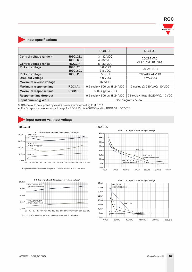
RGC..D.. RGC..A..
Control voltage range 3, 4 RGC..23.. RGC..60..
3 - 32 VDC4 - 32 VDC 20-275 VAC,
24 (-10%) -190 VDCControl voltage range RGC...P 5 - 32 VDCPick-up voltage RGC..23.. RGC..60..
3.0 VDC3.8 VDC 20 VAC/DC
Pick-up voltage RGC..P 5 VDC 20 VAC/ 24 VDCDrop-out voltage 1.0 VDC 5 VAC/DCMaximum reverse voltage 32 VDC -Maximum response time RGC1A.. 0.5 cycle + 500 μs @ 24 VDC 2 cycles @ 230 VAC/110 VDCMaximum response time RGC1B.. 350μs @ 24 VDC -Response time drop-out 0.5 cycle + 500 μs @ 24 VDC 0.5 cycle + 40 μs @ 230 VAC/110 VDCInput current @ 40°C See diagrams below
A1 Characteristics: DC input current vs Input voltagex
RGC..D9xGGEP(Active Protection)
RGC..D
15m
20m
25m
30mA
35m
40m
0mA
5mA
10mA
15mA
20mA
25mA
35mA
40mA
0VAC 50VAC 100VAC 150VAC 200VAC 250VAC 300VAC
RGC .. A
0VDC 50VDC 100VDC 150VDC 200VDC
RGC .. A
RGC..A..P(Normal Operation)
RGC..A..P(Normal Operation)
RGC..A..P(Active Protection)
RGC..A..P(Active Protection)
RGC1 .. A : input current vs input voltage
15m
20m
25m
30mA
35m
40m
0mA
5mA
10mA
15mA
20mA
25mA
35mA
40mARGC1 .. A : input current vs input voltage
250VDC
RGC..A
3. DC control to be supplied by class 2 power source according to UL13104. For GL approved models control range for RGC1.23... is 4-32VDC and for RGC1.60... 5-32VDC
x: Input currents for all models except RGC1..D90GGEP and RGC1..D92GGEP
y: input currents valid only for RGC1..D90GGEP and RGC1..D92GGEP
A1 Characteristics: DC input current vs Input voltagex
RGC..D9xGGEP(Active Protection)
11Carlo Gavazzi Ltd.
RGC
RGC_DS ENG 08/07/21
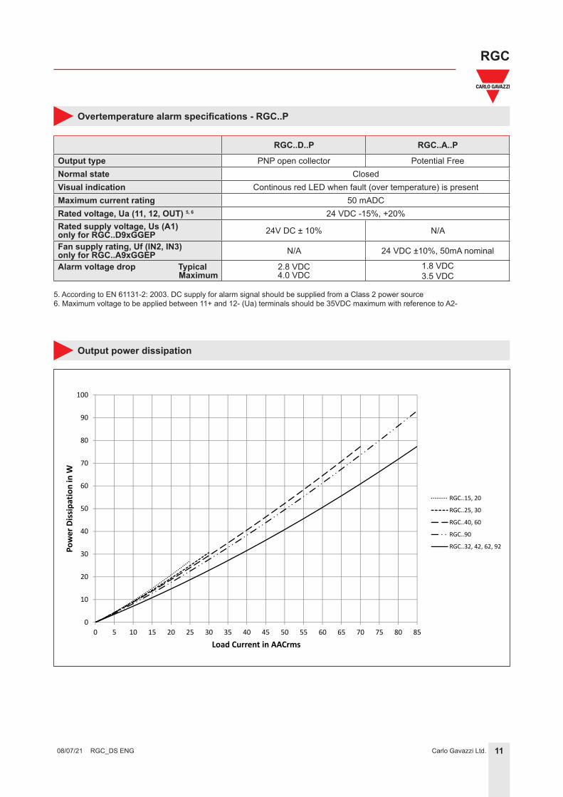
RGC..D..P RGC..A..P
Output type PNP open collector Potential FreeNormal state ClosedVisual indication Continous red LED when fault (over temperature) is presentMaximum current rating 50 mADCRated voltage, Ua (11, 12, OUT) 5, 6 24 VDC -15%, +20%Rated supply voltage, Us (A1)only for RGC..D9xGGEP 24V DC ± 10% N/A
Fan supply rating, Uf (IN2, IN3) only for RGC..A9xGGEP N/A 24 VDC ±10%, 50mA nominal
5. According to EN 61131-2: 2003. DC supply for alarm signal should be supplied from a Class 2 power source6. Maximum voltage to be applied between 11+ and 12- (Ua) terminals should be 35VDC maximum with reference to A2-
12Carlo Gavazzi Ltd.
RGC
RGC_DS ENG 08/07/21
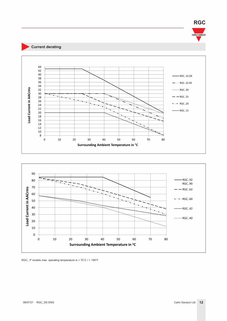
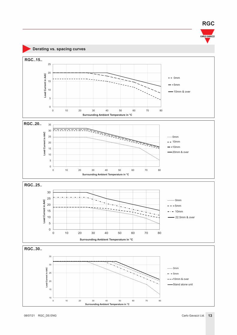
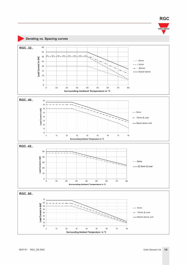
Current derating
8101214161820222426283032343638404244
0 10 20 30 40 50 60 70 80
Load
Current in
AAC
rms
Surrounding Ambient Temperature in °C
RGC..32.GE
RGC..32.KE
RGC..30
RGC..25
RGC..20
RGC..15
0
10
20
30
40
50
60
70
80
90
0 10 20 30 40 50 60 70 80
Load
Current in
AAC
rms
Surrounding Ambient Temperature in oC
RGC..92RGC..90
RGC..62
RGC..60
RGC..42
RGC..40
RGC...P models max. operating temperature is + 70˚C / + 158°F
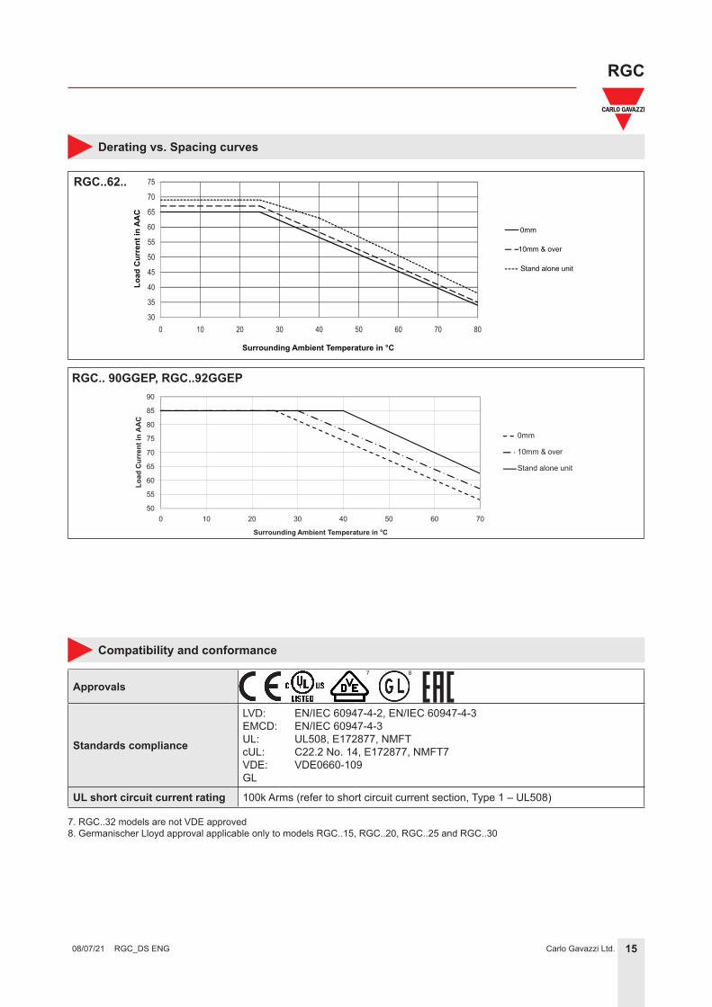
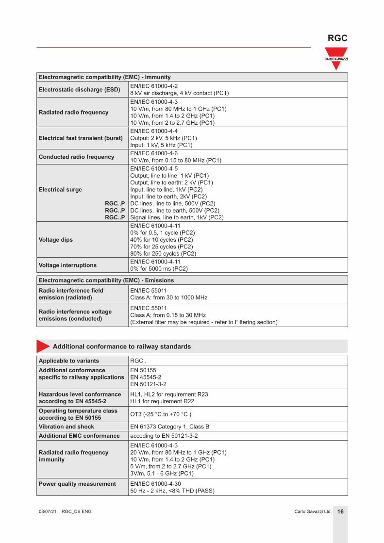
Conducted radio frequency EN/IEC 61000-4-610 V/m, from 0.15 to 80 MHz (PC1)
Electrical surge
RGC..P RGC..P RGC..P
EN/IEC 61000-4-5Output, line to line: 1 kV (PC1)Output, line to earth: 2 kV (PC1)Input, line to line, 1kV (PC2)Input, line to earth, 2kV (PC2)DC lines, line to line, 500V (PC2)DC lines, line to earth, 500V (PC2)Signal lines, line to earth, 1kV (PC2)
Voltage dips
EN/IEC 61000-4-110% for 0.5, 1 cycle (PC2)40% for 10 cycles (PC2)70% for 25 cycles (PC2)80% for 250 cycles (PC2)
Voltage interruptions EN/IEC 61000-4-110% for 5000 ms (PC2)
Electromagnetic compatibility (EMC) - EmissionsRadio interference field emission (radiated)
EN/IEC 55011Class A: from 30 to 1000 MHz
Radio interference voltage emissions (conducted)
EN/IEC 55011Class A: from 0.15 to 30 MHz(External filter may be required - refer to Filtering section)
Applicable to variants RGC..Additional conformance specific to railway applications
EN 50155EN 45545-2EN 50121-3-2
Hazardous level conformance according to EN 45545-2
HL1, HL2 for requirement R23HL1 for requirement R22
Operating temperature class according to EN 50155 OT3 (-25 °C to +70 °C )
Vibration and shock EN 61373 Category 1, Class BAdditional EMC conformance accoding to EN 50121-3-2
Radiated radio frequencyimmunity
EN/IEC 61000-4-320 V/m, from 80 MHz to 1 GHz (PC1)10 V/m, from 1.4 to 2 GHz (PC1)5 V/m, from 2 to 2.7 GHz (PC1)3V/m, 5.1 - 6 GHz (PC1)
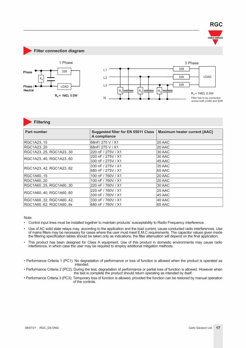
Note:• Control input lines must be installed together to maintain products’ susceptability to Radio Frequency interference.• Use of AC solid state relays may, according to the application and the load current, cause conducted radio interferences. Use
of mains filters may be necessary for cases where the user must meet E.M.C requirements. The capacitor values given inside the filtering specification tables should be taken only as indications, the filter attenuation will depend on the final application.
• This product has been designed for Class A equipment. Use of this product in domestic environments may cause radio interference, in which case the user may be required to employ additional mitigation methods.
• Performance Criteria 1 (PC1): No degradation of performance or loss of function is allowed when the product is operated as intended.
• Performance Criteria 2 (PC2): During the test, degradation of performance or partial loss of function is allowed. However when the test is complete the product should return operating as intended by itself.
• Performance Criteria 3 (PC3): Temporary loss of function is allowed, provided the function can be restored by manual operation of the controls.
1 Phase 3 Phase
18Carlo Gavazzi Ltd.
RGC
RGC_DS ENG 08/07/21
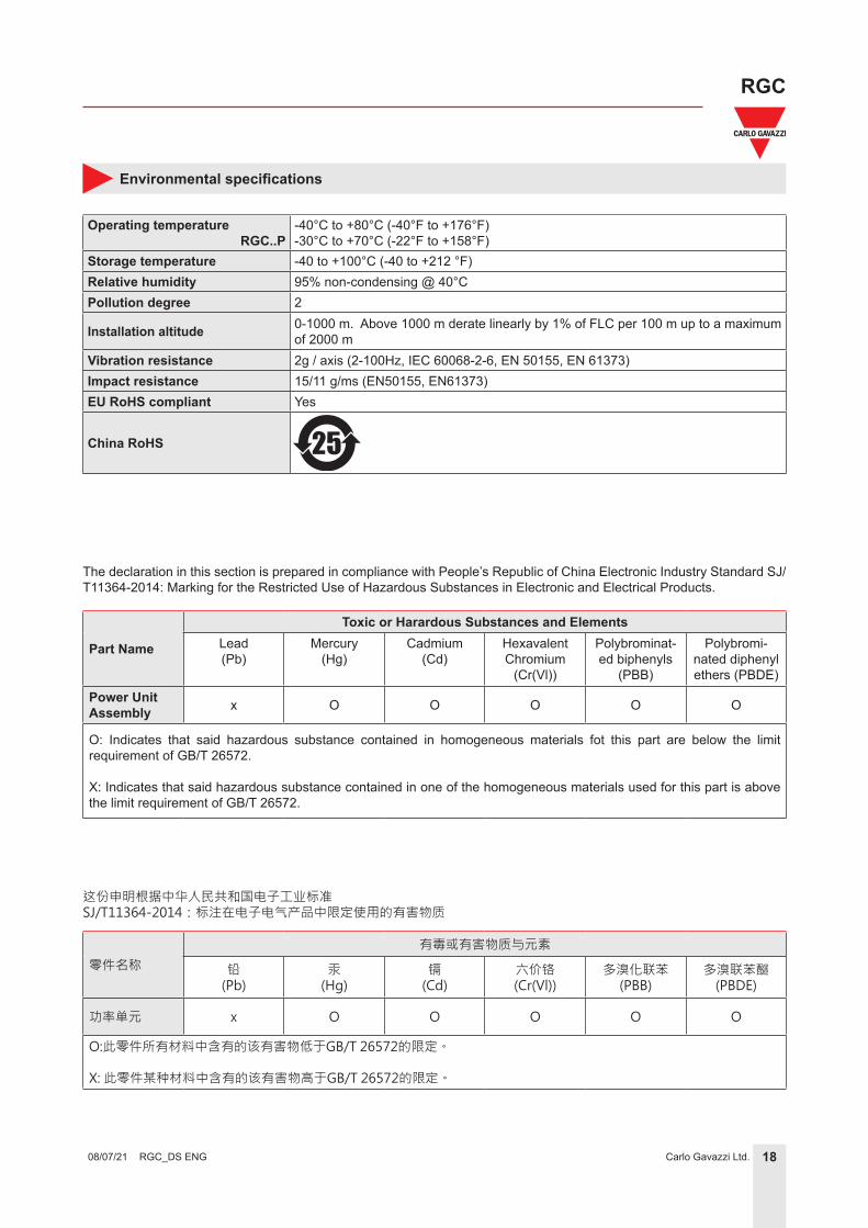
Environmental specifications
Operating temperatureRGC..P
-40°C to +80°C (-40°F to +176°F)-30°C to +70°C (-22°F to +158°F)
Storage temperature -40 to +100°C (-40 to +212 °F)Relative humidity 95% non-condensing @ 40°CPollution degree 2
Installation altitude 0-1000 m. Above 1000 m derate linearly by 1% of FLC per 100 m up to a maximum of 2000 m
Vibration resistance 2g / axis (2-100Hz, IEC 60068-2-6, EN 50155, EN 61373)Impact resistance 15/11 g/ms (EN50155, EN61373)EU RoHS compliant Yes
China RoHS 25
The declaration in this section is prepared in compliance with People’s Republic of China Electronic Industry Standard SJ/T11364-2014: Marking for the Restricted Use of Hazardous Substances in Electronic and Electrical Products.
Toxic or Harardous Substances and ElementsLead(Pb)
Mercury(Hg)
Cadmium(Cd)
Hexavalent Chromium
(Cr(Vl))
Polybrominat-ed biphenyls
(PBB)
Polybromi-nated diphenyl ethers (PBDE)
Power Unit Assembly x O O O O O
O: Indicates that said hazardous substance contained in homogeneous materials fot this part are below the limit requirement of GB/T 26572.
X: Indicates that said hazardous substance contained in one of the homogeneous materials used for this part is above the limit requirement of GB/T 26572.
零件名称
有毒或有害物质与元素
铅(Pb)
汞(Hg)
镉(Cd)
六价铬(Cr(Vl))
多溴化联苯(PBB)
多溴联苯醚(PBDE)
功率单元 x O O O O O
O:此零件所有材料中含有的该有害物低于GB/T 26572的限定。
X: 此零件某种材料中含有的该有害物高于GB/T 26572的限定。
19Carlo Gavazzi Ltd.
RGC
RGC_DS ENG 08/07/21
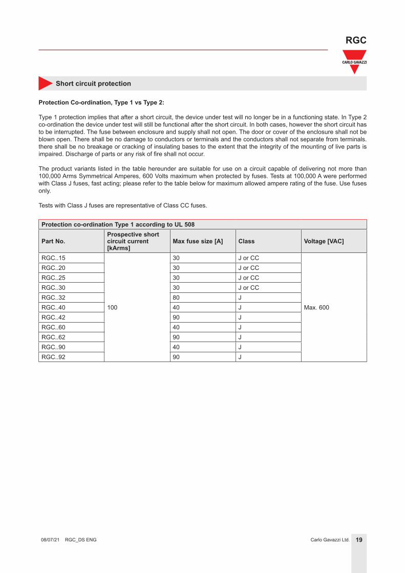
Short circuit protection
Protection Co-ordination, Type 1 vs Type 2:
Type 1 protection implies that after a short circuit, the device under test will no longer be in a functioning state. In Type 2 co-ordination the device under test will still be functional after the short circuit. In both cases, however the short circuit has to be interrupted. The fuse between enclosure and supply shall not open. The door or cover of the enclosure shall not be blown open. There shall be no damage to conductors or terminals and the conductors shall not separate from terminals. there shall be no breakage or cracking of insulating bases to the extent that the integrity of the mounting of live parts is impaired. Discharge of parts or any risk of fire shall not occur.
The product variants listed in the table hereunder are suitable for use on a circuit capable of delivering not more than 100,000 Arms Symmetrical Amperes, 600 Volts maximum when protected by fuses. Tests at 100,000 A were performed with Class J fuses, fast acting; please refer to the table below for maximum allowed ampere rating of the fuse. Use fuses only.
Tests with Class J fuses are representative of Class CC fuses.
Protection co-ordination Type 1 according to UL 508
Part No.Prospective short circuit current [kArms]
Max fuse size [A] Class Voltage [VAC]
RGC..15
100
30 J or CC
Max. 600
RGC..20 30 J or CCRGC..25 30 J or CCRGC..30 30 J or CCRGC..32 80 JRGC..40 40 JRGC..42 90 JRGC..60 40 JRGC..62 90 JRGC..90 40 JRGC..92 90 J
20Carlo Gavazzi Ltd.
RGC
RGC_DS ENG 08/07/21
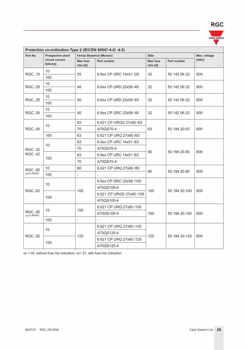
Protection co-ordination Type 2 (IEC/EN 60947-4-2/ -4-3)Part No. Prospective short
circuit current [kArms]
Ferraz Shawmut (Mersen) Siba Max. voltage [VAC]Max fuse
size [A]Part number Max fuse
size [A]Part number
RGC..1510
25 6.9xx CP GRC 14x51 /25 32 50 142 06.32 600100
RGC..2010
40 6.6xx CP URD 22x58 /40 32 50 142 06.32 600100
RGC..2510
40 6.6xx CP URD 22x58 /40 32 50 142 06.32 600100
RGC..3010
40 6.9xx CP GRC 22x58 /40 32 50 142 06.32 600100
RGC..4010
63 6.621 CP URGD 27x60 /63
63 50 194 20.63 60070 A70QS70-4
100 63 6.621 CP URQ 27x60 /63
RGC..32RGC..42
1063 6.9xx CP URC 14x51 /63
80 50 194 20.80 60070 A70QS70-4
10063 6.9xx CP URC 14x51 /63
70 A70QS70-4
RGC..60up to 65AAC
10 80 6.621 CP URQ 27x60 /8080 50 194 20.80 600
100 - -
RGC..62
10
100
6.9xx CP GRC 22x58 /100
100 50 194 20.100 600A70QS100-4
1006.621 CP URGD 27x60 /100
A70QS100-4
RGC..90up to 80AAC
10 1006.621 CP URQ 27x60 /100
100 50 194 20.100 600A70QS100-4
100 - -
RGC..92
10
125
6.621 CP URQ 27x60 /125
125 50 194 20.125 600A70QS125-4
1006.621 CP URQ 27x60 /125
A70QS125-4
xx = 00, without fuse trip indication, xx= 21, with fuse trip indication
21Carlo Gavazzi Ltd.
RGC
RGC_DS ENG 08/07/21
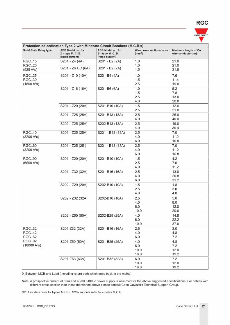
Protection co-ordination Type 2 with Minature Circuit Breakers (M.C.B.s)Solid State Relay type ABB Model no. for
Z - type M. C. B. (rated current)
ABB Model no. for B - type M. C. B. (rated current)
Wire cross sectional area [mm2]
Minimum length of Cu wire conductor [m]9
RGC..15RGC..20(525 A2s)
S201 - Z4 (4A) S201 - B2 (2A) 1.01.01.5
21.021.031.5S201 - Z6 UC (6A) S201 - B2 (2A)
RGC..25RGC..30(1800 A2s)
S201 - Z10 (10A) S201-B4 (4A) 1.01.52.5
7.611.419.0
S201 - Z16 (16A) S201-B6 (6A) 1.01.52.54.0
5.27.813.020.8
S201 - Z20 (20A) S201-B10 (10A) 1.52.5
12.621.0
S201 - Z25 (25A) S201-B13 (13A) 2.54.0
25.040.0
S202 - Z25 (25A) S202-B13 (13A) 2.54.0
19.030.4
RGC..40(3200 A2s)
S201 - Z25 (25A) S201 - B13 (13A) 2.54.06.0
7.011.216.8
RGC..60(3200 A2s)
S201 - Z25 (25 ) S201 - B13 (13A) 2.54.06.0
7.011.216.8
RGC..90(6600 A2s)
S201 - Z20 (20A) S201-B10 (10A) 1.52.54.0
4.27.011.2
S201 - Z32 (32A) S201-B16 (16A) 2.54.06.0
13.020.831.2
S202 - Z20 (20A) S202-B10 (10A) 1.52.54.0
1.83.04.8
S202 - Z32 (32A) S202-B16 (16A) 2.54.06.010.0
5.08.012.020.0
S202 - Z50 (50A) S202-B25 (25A) 4.06.010.0
14.822.237.0
RGC..32RGC..42RGC..62RGC..92(18000 A2s)
S201-Z32 (32A) S201-B16 (16A) 2.54.06.0
3.04.87.2
S201-Z50 (50A) S201-B25 (25A) 4.06.010.016.0
4.87.212.019.2
S201-Z63 (63A) S201-B32 (32A) 6.010.016.0
7.212.019.2
9. Between MCB and Load (including return path which goes back to the mains)
Note: A prospective current of 6 kA and a 230 / 400 V power supply is assumed for the above suggested specifications. For cables with different cross section than those mentioned above please consult Carlo Gavazzi's Technical Support Group.
S201 models refer to 1-pole M.C.B., S202 models refer to 2-poles M.C.B.
22Carlo Gavazzi Ltd.
RGC
RGC_DS ENG 08/07/21
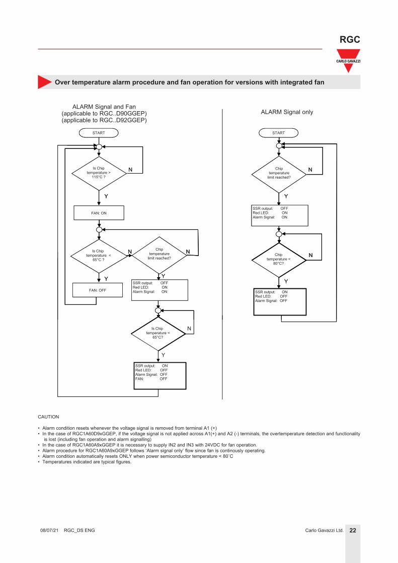
Over temperature alarm procedure and fan operation for versions with integrated fan
ALARM Signal onlyALARM Signal and FAN
START
FAN: ON
Is Chip temperature >
115°C ?
N
Y
Chip temperature <
85°C ?
N
Y
START
N
Y
N
YSSR output: OFFRed LED: ONAlarm Signal: ON
Y
N Chiptemperature <
80°C?
FAN: OFF
Chip temperature
limit reached?
SSR output: ONRed LED: OFFAlarm Signal: OFF
Chip temperature
limit reached?
SSR output: OFFRed LED: ONAlarm Signal: ON
START
FAN: ON
Is Chip temperature >
115°C ?
N
Y
Is Chip temperature <
65°C ?
N
Y
START
N
Y
N
YSSR output: OFFRed LED: ONAlarm Signal: ON
Y
N
Y
Chiptemperature <
80°C?
N
SSR output: ONRed LED: OFFAlarm Signal: OFFFAN: OFF
FAN: OFF
Chip temperature
limit reached?
SSR output: ONRed LED: OFFAlarm Signal: OFF
Is Chip temperature <
65°C?
Chip temperature
limit reached?
SSR output: OFFRed LED: ONAlarm Signal: ON
ALARM Signal and Fan(applicable to RGC..D90GGEP)(applicable to RGC..D92GGEP)
ALARM Signal only
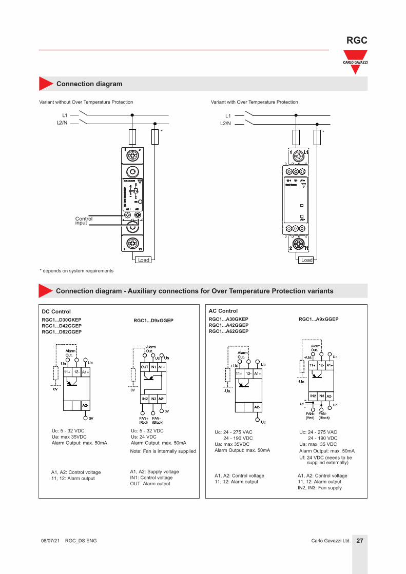
CAUTION
• Alarm condition resets whenever the voltage signal is removed from terminal A1 (+)• In the case of RGC1A60D9xGGEP, if the voltage signal is not applied across A1(+) and A2 (-) terminals, the overtemperature detection and functionality
is lost (including fan operation and alarm signalling)• In the case of RGC1A60A9xGGEP it is necessary to supply IN2 and IN3 with 24VDC for fan operation.• Alarm procedure for RGC1A60A9xGGEP follows ‘Alarm signal only’ flow since fan is continously operating.• Alarm condition automatically resets ONLY when power semiconductor temperature < 80˚C• Temperatures indicated are typical figures.
23Carlo Gavazzi Ltd.
RGC
RGC_DS ENG 08/07/21
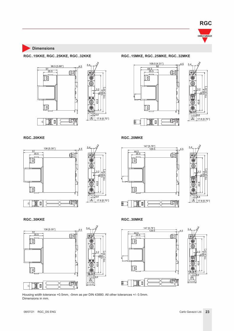
Dimensions
RGC..15KKE, RGC..25KKE, RGC..32KKE
98.5 [3.88’’] 4.551
35.5
5.4
3.2
110
[4.3
3’’]
100.
490
43.8
4.48 17.8 [0.70’’]
Ø 4
.4
Housing width tolerance +0.5mm, -0mm as per DIN 43880. All other tolerances +/- 0.5mm.Dimensions in mm.
RGC..20KKE
5.4
3.2
110
[4.3
3’’]
100.
490
43.8
4.48 17.8 [0.70’’]
Ø 4
.4
136 [5.35’’] 4.551
35.5
RGC..30KKE
136 [5.35’’] 4.551
35.5
3.2
43.8
100.
411
0 [1
.33’
’]
90
5.4
4.4
22.5 [0.89’’]17.8
8
Ø 4
.4
RGC..15MKE, RGC..25MKE, RGC..32MKE
17.8 [0.70’’]84.4
43.8
90 100.
411
0 [4
.33’
’]
5.4
3.2
Ø 4
.44.5109.5 [4.31’’]
44.535.5
92
RGC..20MKE
17.8 [0.70’’]84.4
43.8
90 100.
411
0 [4
.33’
’]
5.4
3.2
Ø 4
.4147 [5.78’’]129.5 4.5
44.535.5
RGC..30MKE
147 [5.78’’]129.5 4.5
44.535.5
5.4
90 100.
411
0 [4
.33’
’]
Ø 4
.443
.8
3.2
4.4
22.5 [0.89’’]17.8
8
24Carlo Gavazzi Ltd.
RGC
RGC_DS ENG 08/07/21
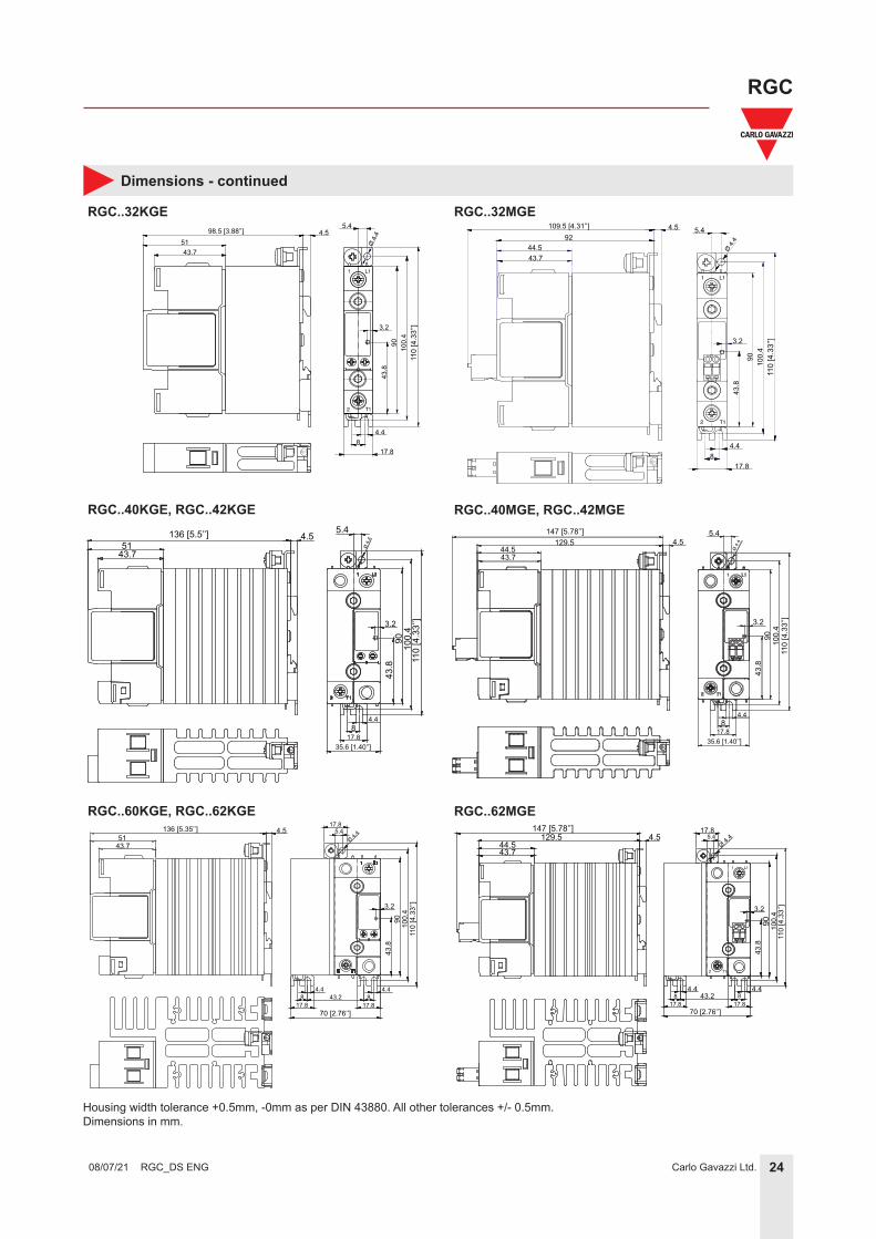
Dimensions - continued
RGC..32KGE98.5 [3.88’’]
5143.7
4.55.4
Ø 4
.4
817.8
4.4
110
[4.3
3’’]
100.
490
43.8
3.2
Housing width tolerance +0.5mm, -0mm as per DIN 43880. All other tolerances +/- 0.5mm.Dimensions in mm.
RGC..32MGE
RGC..40KGE, RGC..42KGE
5143.7
4.5136 [5.5’’]
817.8
4.4
35.6 [1.40’’]
5.4
Ø 4
.4
110
[4.3
3’’]
100.
490
43.8
3.2
RGC..60KGE, RGC..62KGE
5143.7
136 [5.35’’] 4.5
110
[4.3
3’’]
100.
490
43.8
3.2
5.4Ø 4.
417.8
817.8
4.4
70 [2.76’’]
817.8
4.443.2
T12
L11
109.5 [4.31’’]
44.543.7
4.592
817.8
4.4
110
[4.3
3’’]
100.
490
43.8
3.2
5.4
Ø 4.4
RGC..40MGE, RGC..42MGE
44.543.7
147 [5.78’’]129.5 4.5
5.4
Ø 4
.4
110
[4.3
3’’]
100.
490
43.8
3.2
817.8
4.4
35.6 [1.40’’]
RGC..62MGE
44.543.7
147 [5.78’’]4.5129.5
110
[4.3
3’’]
100.
490
43.8
3.2
817.8
4.4
70 [2.76’’]
817.8
4.443.2
5.4Ø 4.
417.8
25Carlo Gavazzi Ltd.
RGC
RGC_DS ENG 08/07/21
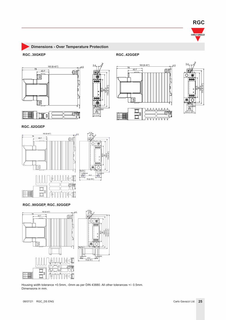
Dimensions - Over Temperature Protection
RGC..30GKEP
163 [6.42’’]78
43.7
4.5
817.8
22.5 [0.89’’]
4.411
0 [4
.33’
’]10
0.4
9060.5
5.4 Ø 4
.4
RGC..62GGEP
163 [6.42’’] 4.578
43.7
5.417.8
Ø 4.4
110
[4.3
3’’]
100.
49060
.5
817.8
4.48
17.8
4.4
70 [2.76’’]
43.2
RGC..42GGEP
163 [6.42’’]78
43.7
4.5 5.4
817.8
35.6 [1.40’’]
4.4
110
[4.3
3’’]
100.
49060
.5Ø
4.4
RGC..90GGEP, RGC..92GGEP
84.4
84.4
70 [2.76’’]43.2
110
[4.3
3’’]
9060.5
130
[5.1
2’’]
100.
4
5.417.8
Ø 4.4163 [6.42’’] 4.5
7843.7
Housing width tolerance +0.5mm, -0mm as per DIN 43880. All other tolerances +/- 0.5mm.Dimensions in mm.
26Carlo Gavazzi Ltd.
RGC
RGC_DS ENG 08/07/21
Terminal layout
L11
T12
hctiwS etatS diloS
GR
CARLO GAVAZZI
A1 A2
ON
A1L1
T1A2
L11
T12
L11
T12
hctiwS etatS diloS
GR ON
A1 L1
T1A2
A1 A2
L11
T12
A2-
RG
Sol
id s
tate
Sw
itch
FAULT
CONTROL
A1+SUPPLYCONTROLALARM
OUT IN1
GND
L11
T12
A1
A2
11+
IN3IN2
12- A1
A2
11+
IN3IN2
12-
hctiwS etatS diloS
GR
FAULT
CONTROL
A1
A2FAN -FAN + GNDGND
SUPPLYCONTROLALARM
OUT
IN3IN2
IN1
L11
T12T12
L11
A1
A2
11+
IN3IN2
12- A1
A2
11+
IN3IN2
12- A1
A2
11+
IN3IN2
12-
L11
T12
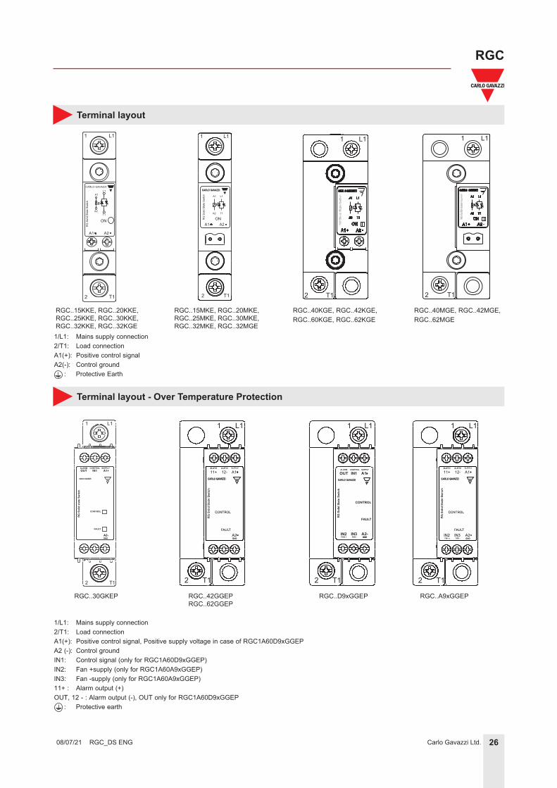
1/L1: Mains supply connection2/T1: Load connectionA1(+): Positive control signal, Positive supply voltage in case of RGC1A60D9xGGEPA2 (-): Control groundIN1: Control signal (only for RGC1A60D9xGGEP)IN2: Fan +supply (only for RGC1A60A9xGGEP)IN3: Fan -supply (only for RGC1A60A9xGGEP)11+ : Alarm output (+)OUT, 12 - : Alarm output (-), OUT only for RGC1A60D9xGGEP : Protective earth
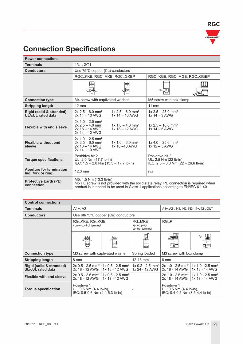
Aperture for termination lug (fork or ring) 12.3 mm n/a
Protective Earth (PE)connection
M5, 1.5 Nm (13.3 lb-in)M5 PE screw is not provided with the solid state relay. PE connection is required when product is intended to be used in Class 1 applications according to EN/IEC 61140
Connection Specifications
Control connectionsTerminals A1+, A2- A1+, A2-, IN1, IN2, IN3, 11+, 12-, OUT
Conductors Use 60/75°C copper (Cu) conductorsRG..KKE, RG..KGEscrew control terminal
RG..MKEspring plug control terminal
RG..P
Connection type M3 screw with captivated washer Spring loaded M3 screw with box clamp
Stripping length 8 mm 12-13 mm 6 mmRigid (solid & stranded)UL/cUL rated data