Page 1
ROAD ORDINANCE
CHAPTER 276
Department of Planning & Growth Management
Adopted January 1985
Revised October 1992
Revised January 1995
Revised September 1998
Revised December 2000
Revised December 2002
Revised November 2003
Appendix Revised April 2008
Appendix Revised April 2009
Revised June 2011
Appendix Revised June 2013
Revised June 2015 Revised January 2017
Appendix Revised October 2018
Appendix Revised October 2019
Page 2
Vision Statement
Charles County is a place where...
* All people thrive and businesses grow and prosper; where the
preservation of our heritage and environment is paramount;
* Government services to its citizens are provided at the highest level of
excellence; and
* The quality of life is the best in the nation.
Mission Statement
The Mission of Charles County Government is to provide our citizens the highest
quality service possible in a timely, efficient, and courteous manner. To achieve
this goal, our government must be operated in an open and accessible
atmosphere, be based on comprehensive long- and short term-planning, and have
an appropriate managerial organization tempered by fiscal responsibility.
Page 3
ROAD ORDINANCE – JANUARY 2017 TOC-1
ROAD ORDINANCE
TABLE OF CONTENTS
Section Subject Page
ARTICLE I. SCOPE
276-1 Applicability ...........................................................................................................1
ARTICLE II. DEFINITIONS
276-2 Definitions................................................................................................................2
ARTICLE III. MINIMUM DESIGN REQUIREMENTS ........................................................5
276-3 Introduction
A. General ..............................................................................................................5
B. Continuity of Typical Section .........................................................................5
276-4 Design Controls
A. Average Daily Traffic Volume (ADT) ............................................................5
B. Design Speed .....................................................................................................5
C. Design Vehicle ..................................................................................................6
276-5 Horizontal and Vertical Alignment
A. Introduction ......................................................................................................7
B. Horizontal Alignment ......................................................................................8
C. Horizontal Curves ............................................................................................9
D. General Controls for Horizontal Alignment ...............................................10
E. Vertical Alignment .........................................................................................11
F. Grades .............................................................................................................11
G. Vertical Curves...............................................................................................11
H. General Controls for Vertical Alignment ....................................................11
Page 4
Section Subject Page
ROAD ORDINANCE – JANUARY 2017 TOC-2
276-6 Cross Section Elements
A. Typical Sections ..............................................................................................12
B. Pavement Widths and Cross-Slope ..............................................................14
C. Pavement Thickness.......................................................................................14
D. Curb and Gutter ............................................................................................14
E. Shoulders ........................................................................................................14
F. Medians ...........................................................................................................14
G. Pedestrian Travel Ways ................................................................................15
H. Side Slopes ......................................................................................................16
I. Guardrail ........................................................................................................16
J. Utility Location...............................................................................................16
276-7 Intersection Design
A. Introduction ....................................................................................................17
B. Geometric Design ...........................................................................................17
C. Auxiliary Lanes/Turning Lanes ...................................................................17
D. Median Lanes and Openings.........................................................................18
E. Traffic Islands ................................................................................................19
F. Intersection Sight Distance............................................................................19
G. Intersection Vertical Alignment ...................................................................20
H. Pedestrian Facilities .......................................................................................20
I. Right-of-Way at Intersection ........................................................................21
J. Intersections with State Highways ...............................................................21
276-8 Entrances ...............................................................................................................21
276-9 Off-Street Parking Lots........................................................................................21
276-10 Pavement Sections ..............................................................................................22
276-11 At Grade Crossing for Golf Cart ......................................................................22
276-12 Roundabout .........................................................................................................22
276-13 School Bus Turnaround .....................................................................................22
Page 5
Section Subject Page
ROAD ORDINANCE – JANUARY 2017 TOC-3
276-14 Curb Openings ....................................................................................................23
276-15 Access Management for County Roads ............................................................23
A. Policy in General ............................................................................................23
B. Locating Median Openings and Access Points ............................................23
C. Addition to or Modification of Access Management Tables ......................24
276-16 Urban Roads .......................................................................................................24
ARTICLE IV. DRAINAGE
276-17 Storm Drainage ...................................................................................................25
ARTICLE V. PERMITS
276-18 Permits .................................................................................................................26
A. General Requirements ...................................................................................26
B. Permit Application .........................................................................................26
C. Right-of-Way ..................................................................................................26
D. Alternate Standards .......................................................................................26
E. Permit Expiration ..........................................................................................26
276-19 Permits for Utilities ............................................................................................26
A. Permission .......................................................................................................26
B. Emergency ......................................................................................................26
C. Restoration......................................................................................................27
D. Processing .......................................................................................................27
E. Blanket Permits ..............................................................................................27
276-20 Fees .......................................................................................................................27
276-21 Bonds....................................................................................................................27
276-22 Road Plans ...........................................................................................................28
276-23 Construction Requirements ...............................................................................28
Page 6
Section Subject Page
ROAD ORDINANCE – JANUARY 2017 TOC-4
276-24 Variances/Exemptions ........................................................................................30
276-25 Transitional Provisions ......................................................................................30
276-26 Interpretation of Standards ...............................................................................31
276-27 Inspection and Acceptance ................................................................................31
276-28 Approval and Acceptance ..................................................................................31
A. Final Approval ...............................................................................................31
B. Acceptance ......................................................................................................31
C. Partial Acceptance .........................................................................................31
D. As-Built Drawings .........................................................................................32
276-29 Penalties ...............................................................................................................32
ARTICLE VI. TRAFFIC
276-30 Introduction ........................................................................................................33
276-31 Traffic Signs and Pavement Markings .............................................................33
276-32 Railroad At-Grade Crossings ............................................................................34
276-33 Maintenance and Protection of Pedestrian and Vehicular Traffic ................34
276-34 Streetlight Policy .................................................................................................34
276-35 Privately Owned Structures ..............................................................................34
ARTICLE VII. NEIGHBORHOOD TRAFFIC CALMING PROGRAM
276-36 New Residential Subdivision Roads ..................................................................36
276-37 Existing Residential Subdivision Roads ...........................................................37
APPENDICES
A. Tables
2.01.01 Summary of Design Criteria .................................................................39
2.01.02 Summary of Design Criteria – Designated Urban Areas ...................40
Page 7
Section Subject Page
ROAD ORDINANCE – JANUARY 2017 TOC-5
2.02 Stopping Sight Distance .........................................................................41
2.03 Minimum Intersection Spacing .............................................................42
2.04 Minimum Lengths of Vertical Curves ..................................................43
2.05 Minimum Curvature for Turning Movements ....................................44
2.06 Sight Distance at Intersection ................................................................45
2.07 Pavement Detail ......................................................................................46
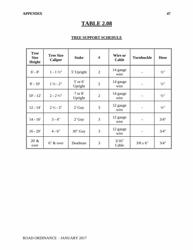
2.08 Tree Support Schedule ...........................................................................47
2.09 Recommended List of Trees for Street Planting .................................48
2.10 Minimum Passing Sight Distance .........................................................50
2.11 Minimum Lengths of Auxiliary Lanes .................................................51
B. Guardrail Required for Embankment Geometry .............................................52
C. Standards and Guidelines for Traffic Signs and Markings in New
Subdivisions ..........................................................................................................53
D. Maintenance of Traffic ........................................................................................54
E. Charles County Ordinance for the Naming and Renaming of Streets
and the Assignment of Address Numbers ..........................................................55
F. Access Management Tables ................................................................................61
G. Urban Road Standards District ..........................................................................76
H. References .............................................................................................................77
I. Neighborhood Traffic Calming Program ..........................................................78
Page 8
I. SCOPE
1
ROAD ORDINANCE – JANUARY 2017
ARTICLE I – SCOPE
276-1 APPLICABILITY
This chapter shall apply to the design, construction, improvement, maintenance, and repair of roads
within the unincorporated area of Charles County as required by the Subdivision Regulations and
Zoning Ordinance.
Page 9
II. DEFINITIONS 2
ROAD ORDINANCE – JANUARY 2017
ARTICLE II - DEFINITIONS
276-2 DEFINITIONS
For the purpose of these regulations, certain terms are defined as follows:
Alley: A private roadway located in the Urban Road Standards District which provides secondary
service access for vehicles to the rear or side of abutting properties. The naming of alleys shall
end with “alley”.
Collector Roads: Public roadways which, in addition to providing access to properties abutting
thereon, are intended to collect traffic from, or distribute it to, a series of streets within a
neighborhood or sub-neighborhood. The naming for collector roads shall be as defined in Tables
2.01.01 and 2.01.02.
County: The term shall mean Charles County, Maryland a Body Corporate and Politic.
County Highway Engineer: The official designated by the County Commissioners to administer
this chapter.
Driveway: A private access road, drive, or land to an individual lot or parcel which is contained
within the lot or parcel and is not intended to serve any other lot or parcel of land.
Easement: A strip of land on which a limited right-of-way is provided for one or more designated
purposes, without including title to the land.
Entrance: The area within the public right-of-way providing a vehicle connection to a private
road, drive or driveway.
Grid Address Numbering System: The mathematical computation of mailing address hundred
blocks based on Charles County map, scale 600 feet to the inch.
Hiker/biker Path: A pathway physically separated from motorized vehicular traffic by an open
space or barrier and either within public right-of-way or within their own right-of-way.
House Number: The mailing address digital number and street name assigned to any structure or
parcel of land.
Local Roads: A public roadway contained within a public right-of-way to provide direct access
to abutting properties. The naming for local roads shall end with "court," "lane," "street,"
“avenue,” and "way." They are defined as follows:
Court: A public roadway that ends in a cul-de-sac contained within a public right-of-way
to provide access to properties.
Page 10
II. DEFINITIONS 3
ROAD ORDINANCE – JANUARY 2017
Street/lane/avenue: A public roadway that is not a court contained within a public right-
of-way to provide access to properties.
Way: A public roadway contained within a public right-of-way consisting of a small loop,
or "horseshoe" with two access points with a maximum depth of three hundred (300) feet
or a one-way "eye brow" configuration with a maximum depth of one hundred (100) feet
to provide access to residential dwellings.
Lot Frontage: The distance for which the front boundary line of the lot and the street line are
coincident.
Natural Trail: A hiker-biker path through or within Resource Protection Zone, the Chesapeake
Bay Critical Area, or other environmentally sensitive areas.
Neighborhood Traffic Calming Program (NTCP) : A program for residential local and minor
collector roads to promote and encourage safety and livability by reducing speeds and/or traffic
volumes in residential neighborhoods. Program details are contained in Appendix I of this chapter.
Parcel of Land: Any lot, parcel, dock, pier, or wharf used to identify the site where a dwelling or
place of business and/or storage is to be erected, located, or situated.
Pedestrian Travel Way: A travel way designed for exclusive use by pedestrians within public
right-of-way or within their own right-of-way.
Private Roads and Private Drives: Refers to non-government maintained roadways. The
naming of all private roads shall end with "place". The following are the various types of private
roads:
Private Drive: A private driveway contained within a private easement/right-of-way to
provide access to a maximum of seven (7) single-family detached dwellings.
Private Road: A private road which provides access to multi-family dwelling units, non-
residential units or a maximum of 65 single-family attached dwelling units. A private road
may be required to be within an easement/right-of-way.
Property: A building, structure, or parcel of land or the combination of any of the above.
Public Road: Refers to government maintained roadways.
Public Utility: A business or service which is engaged in regularly supplying a commodity or
service of public need such as electricity, gas, water, sewer, and telephone.
Public Right-of-way: Grants fee simple title for continuous access through, over, under, and
across property.
Speed Control Measures: Measures used to control speed in residential neighborhoods. During
the road design process this may include road curvature, breaks in road continuity (for example:
roads that end in a T-intersection instead of long, through roads), traffic circles and roundabouts.
Page 11
II. DEFINITIONS 4
ROAD ORDINANCE – JANUARY 2017
It may also include Level 2 traffic calming measures as described in the neighborhood traffic
calming program (NTCP) contained in Appendix I of this chapter.
Street Direction: The direction any street or road travels the longest in distance.
MSHA: Shall mean the Maryland State Highway Administration.
Urban Road: A public road located in the Urban Road Standards District. A map of the urban
road standards district is shown in appendix G.
Page 12
III. MINIMUM DESIGN REQUIREMENTS 5
ROAD ORDINANCE – JANUARY 2017
ARTICLE III – MINIMUM DESIGN REQUIREMENTS
276-3 INTRODUCTION
A. General
(1) This chapter presents criteria and guidelines for the design of roads, streets,
driveways, and off-street parking lots. The criteria and guidelines have been
developed considering the intended role of the street in relation to service
function, land use, traffic demand, quality of service, vehicular and
pedestrian safety, economy, and the environment.
(2) Tables 2.01.01 and 2.01.02 give a summary of the basic design criteria
which are developed in this chapter.
B. Continuity of Typical Section
When a road is constructed in segments at various times or traverses varying zoning
districts, the County may require certain design features (e.g. curb type, paving
width, etc.) not otherwise required by this manual or may waive these design
features in order to provide continuity of the typical section.
276-4 DESIGN CONTROLS
The three principal values controlling design of roads and streets are average daily traffic
volume (ADT), design speed, and design vehicle. These values form the basis for the
selection of the geometric elements that are required to accommodate the anticipated traffic
at a desired quality of service.
A. Average Daily Traffic Volume (ADT)
(1) Average daily traffic volume will be the design control as shown in Article
VII, Section 72 - Functional Classification of Roads, of the Charles County
Subdivision Regulations. In cases of lower classification of streets, trip
generation rates may be used in lieu of average daily traffic.
B. Design Speed
(1) Design speed is the maximum safe speed that can be maintained over a
given section of road when the traffic volume is so low that the geometrics
of the roadway control speed. All elements should be in balance consistent
with a specified design speed. Stopping sight distance, horizontal and
vertical alignment, and superelevation are among the roadway elements
which are controlled by design speed. The minimum design values for the
various elements required for a given design speed should be used only
where controls such as topography and property damages dictate their use.
Page 13
III. MINIMUM DESIGN REQUIREMENTS 6
ROAD ORDINANCE – JANUARY 2017
On local and minor collector residential streets it is desirable to keep speeds
low, and care must be exercised that the design does not encourage high
speeds without sacrificing any of the design standards included herein.
Speed control measures shall be incorporated into the design of all
residential local and minor collector roads longer than 1500 feet which are
located within the Development District.
(2) Unless otherwise approved by the County, the minimum design speeds
listed in tables 2.01.01 and 2.01.02 shall be used for the design of roads.
For existing County roads whose classification is unknown the design speed
shall be the posted speed plus 10 mph.
C. Design Vehicle
(1) The design vehicle is the motor vehicle whose characteristics determine
such geometric elements as vertical clearance and turning radii. Vehicles
have been divided into six classes and a typical design vehicle has been
developed for each. The respective design vehicles have dimensions and a
minimum turning radius larger than those of almost all vehicles in the
respective classes.
(2) The six design vehicle designations are as follows:
(a) P (Passenger car)
(b) SU (Single unit truck)
(c) BUS (Single unit bus)
(d) WB-40 (Semitrailer combination, intermediate)
(e) WB-50 (Semitrailer combination, large)
(f) WB-60 (Semitrailer - full trailer combination)
(3) Dimensions and turning characteristics of each design vehicle are contained
in Reference 1.
(4) Though a road must be designed to accommodate the largest vehicle likely
to use it, the selection of too large a design vehicle can have an adverse
effect, such as longer crosswalks at the intersections. The design vehicle
must be selected considering the street classification and adjacent land uses.
Its selection is subject to review and approval by the County.
(5) In no case shall a public road, private road or commercial/industrial
entrance be so designed that it cannot accommodate a WB-40 vehicle and a
fire truck with an inside turning radius of 35.5 feet and an outside turning
radius of 46 feet and an overhang of 2.5 feet.
Page 14
III. MINIMUM DESIGN REQUIREMENTS 7
ROAD ORDINANCE – JANUARY 2017
276-5 HORIZONTAL AND VERTICAL ALIGNMENT
A. Introduction
(1) General
(a) All roads should be designed to take full advantage of the existing
topography and offer scenic views wherever possible.
(b) The horizontal and vertical alignment should be designed together
to assure a smooth continuous route. Design procedures which
include the careful coordination of the vertical and horizontal
alignment will result in a safer, more aesthetic and more economical
design. The horizontal curve should be longer than the vertical
curve at a given location so that the driver can easily perceive
changes in horizontal alignment. Sharp horizontal curves should be
avoided at the bottom of long steep grades because vehicular speeds
may be high, making it difficult to travel on the curve, especially
under slippery conditions.
(c) The design for both horizontal and vertical alignment should be such
that no unexpected features are presented to the driver. A sharp
horizontal curve should not be introduced after a long stretch of
tangents and flat curves; rather, the curves should become
progressively sharper to accustom the driver to the larger centrifugal
forces.
(2) Sight Distance
(a) Sight distance is the length of visible roadway ahead of the driver.
The two types of sight distance considered in design are stopping
(or non-passing) sight distance and passing sight distance. Sight
distance shall be made as long as feasible, but never less than the
stopping sight distance.
(b) The sight distance required at intersections is presented in §276-7F.
(3) Stopping Sight Distance
(a) Stopping sight distance (SSD) is the distance required for a vehicle
to stop before reaching an object in its path. It is the sum of the
distance traveled from the moment the object is first visible to the
driver to the moment the brakes are applied, and the distance
required to stop after the brakes are applied.
Page 15
III. MINIMUM DESIGN REQUIREMENTS 8
ROAD ORDINANCE – JANUARY 2017
(b) The equation for stopping sight distance is:
SSD = 3.67 V + V2
30 (F ± G)
where:
V = initial speed, mph
F = coefficient of friction between tires and roadways for
wet pavement
G = percent of algebraic grade divided by 100
(c) Stopping sight distances on a level roadway for various design
speeds are shown in Table 2.02.
(d) Stopping sight distance is measured between an eye height of 3.5
feet and an object height of 6 inches.
(e) The relationships between horizontal curvature and sight distance,
and vertical curvature and sight distance, are given in Sections
3.3.C.3 and 3.3.G respectively.
(4) Passing Sight Distance
(a) Passing Sight Distance (PSD) is the distance required for a vehicle
to pass another before meeting an opposing vehicle which might
appear after the pass began. It is applicable only to two-lane, two-
way rural major collectors, and minor arterials.
(b) Passing sight distance is measured between an eye height of 3.5 feet
and an object height of 4.25 feet.
(c) The minimum passing sight distance should be provided at least
once per mile.
(d) Table 2.10 contains minimum passing sight distances for various
design speeds.
B. Horizontal Alignment
(1) Intersection Location and Spacing
(a) Roads should be so located that sufficient length is provided
between intersections for weaving, storage, and associated land
uses. The minimum intersection spacing, measured along the
through roadway between the centerline of intersecting roadways,
shall be as indicated in Table 2.03.
Page 16
III. MINIMUM DESIGN REQUIREMENTS 9
ROAD ORDINANCE – JANUARY 2017
(2) Cul-De-Sac Streets and Turnarounds
(a) The design of single access streets such as cul-de-sacs shall be as
specified in tables 2.01.01 and 2.01.02. Streets which are
permanently designed with only one end open to traffic shall be
terminated in a cul-de-sac as shown in the Charles County Standard
Detail Manual. In the event a street will be extended in the future
under a planned project for which a preliminary plan has been
approved, a temporary “T” turnaround shall be provided as shown
in the Charles County Standard Detail Manual R/2.19.
C. Horizontal Curves
(1) General
(a) Horizontal curves are used to change direction at a safe rate and shall
be used wherever the roadway centerlines change direction.
(b) Reverse curves and compound curves are a combination of simple
curves and criteria governing their use are included in Section 3.3.D.
(2) Degree of Curve, Superelevation, and Design Speed
(a) The relationship between design speed, curvature and
superelevation is:
E + F = V2 = DV2
15R 85900
where:
E = rate of superelevation, ft/ft
F = side friction factor
V = design speed, mph
R = radius of curve, ft
D = degree of curve
(b) The design speed shall be as set forth in Tables 2.01.01 and 2.01.02.
(c) Maximum superelevation rates are dependent upon the type of
roadway, the effect of the superelevation upon vehicles operating at
less than the design speed and drainage considerations.
(d) Roads designed with a design speed of 50 mph and greater shall be
superelevated. The maximum superelevation rate to be used is 6%.
Two-thirds of the superelevation runoff shall be placed on the
tangent and one-third on the curve. Roads shall be superelevated in
accordance with AASHTO standards.
Page 17
III. MINIMUM DESIGN REQUIREMENTS 10
ROAD ORDINANCE – JANUARY 2017
(3) Horizontal Sight Distance
(a) Another control on horizontal alignment is the sight distance across
the inside of curves. Where there are sight obstructions such as
building, trees, hedges, walls, guardrail, or cut slopes, efforts shall
be made to provide as long a sight distance as feasible, but never
less than the stopping sight distance given in Table 2.02.
(b) Where there are no sight obstructions within the right-of-way, the
right-of-way line shall be used as the sight obstruction or alternately
by the inclusion of an easement on a record plat to maintain a clear
line of sight zone.
D. General Controls for Horizontal Alignment
In addition to the specific criteria presented in previous sections, the following
general controls shall be utilized:
(1) In selecting the alignment for a given design speed, use of the maximum
curvature (i.e. minimum radius) for that speed should be avoided except
where beneficial for traffic calming purposes.
(2) Consideration shall be given to the alignment and its effect on running
speed. The speed at the bottom of a long downgrade, for example, will be
higher than on a level grade, and this shall be considered when introducing
a horizontal curve.
(3) The minimum radius of horizontal curves shall be as shown in Tables
2.01.01 and 2.01.02.
(4) Sharp curvature shall be avoided on long high hills. The absence of such
reference items as cut slopes, trees, and buildings makes it difficult for the
driver to judge horizontal curvature.
(5) In compound circular curves, the radius of the flatter curve should not be
more than 1.5 times greater than the radius of the sharper curve.
(6) Where reverse curves are used a minimum of 100 feet tangent shall be
provided between the curves.
(7) Broken back curves, that is, two curves in the same direction separated by
a short tangent, should be avoided.
Page 18
III. MINIMUM DESIGN REQUIREMENTS 11
ROAD ORDINANCE – JANUARY 2017
E. Vertical Alignment
(1) Vertical alignment shall be designed considering the design speed and road
classification in order to provide a balance between all geometric elements
of the road.
(2) The two components of vertical alignment are grades and vertical curves.
Minimum grades are established to assure adequate drainage, and maximum
grades are established considering the operational characteristics of the
design vehicle. Vertical curves must be at least long enough to provide the
required stopping sight distance.
(3) Vertical alignment is controlled by a profile grade line (PGL) shown on the
standard details.
(4) Control for profiles at intersections are contained in Section 3.5.G.
F. Grades
(1) The minimum grade for all roads and streets shall be 1.0 % unless otherwise
approved by the County. Where a curbed section is used, the spacing of
inlets must be carefully studied when utilizing the minimum grade to avoid
the spreading of storm water across the pavement.
(2) The maximum grade in a cul-de-sac bulb shall not exceed 6%.
(3) The maximum grade varies with road classification and is shown in Tables
2.01.01 and 2.01.02.
G. Vertical Curves Minimum lengths of vertical curves are shown on Table 2.04.
(1) Crest Vertical Curves. Crest vertical curves must be sufficiently long to
provide the required stopping sight distance as listed in Table 2.02.
(2) Sag Vertical Curves. Sag vertical curves must be sufficiently long to
assure that a driver has sufficient distance in which to stop after his
headlights first reveal an object on the roadway. Minimum lengths of sag
vertical curves shall therefore be based upon a headlight sight distance equal
to the stopping sight distance.
H. General Controls for Vertical Alignment
In addition to the specific criteria presented in previous sections, there are a number
of general controls applicable to vertical alignment.
(1) In selecting the vertical alignment based on a given design speed, use of the
maximum gradient and minimum length of curve for that speed should be
avoided.
Page 19
III. MINIMUM DESIGN REQUIREMENTS 12
ROAD ORDINANCE – JANUARY 2017
(2) The length of vertical curve shall not be less than three times the design
speed in m.p.h.
(3) The length of vertical curve shown in the linear profile around the cul-de-
sac bulb at the curb line for closed section roadways shall not exceed 25
feet.
(4) A smooth profile grade, consistent with the topography, shall be strived for
in preference to a grade with numerous breaks and short lengths of tangent.
(5) The profile shall be such that hidden dips hazardous to passing maneuvers
are avoided.
(6) Short tangents of less than 50 ft. between vertical curves shall be avoided.
(7) Where there is an at-grade intersection on a highway with a steep grade, the
gradient should be reduced through the intersection to aid turning vehicles
and reduce hazards. Specific criteria are contained in Section 3.5.G.
276-6 CROSS-SECTION ELEMENTS
A. Typical Sections
(1) Unless otherwise approved by the County, typical paving sections for the
various functional classifications are shown in Tables 2.01.01 and 2.01.02.
(2) Private drives - When provided for by the Zoning Ordinance and/or
Subdivision Regulations, for single-family detached residential lots, the
following conditions apply:
(a) Where two or more lots are proposed to be served by the same
common access easement or private right-of-way, such common
access easement or private right-of-way shall have a minimum
width of thirty (30) feet.
(b) Parking spaces shall not be provided within that portion of private
drives which serve two or more lots.
(c) The responsibilities for private drive maintenance shall be clearly
stated in covenants, in a form acceptable to the Planning
Commission, which shall be filed in the land records at the time of
filing of the final plat, and a certification shall be included on the
final plat to the effect that the subdivision is subject to covenants.
(d) For lots less than one acre in size, the drive shall be a minimum of
two inches of asphalt pavement on six inches bank run gravel base.
Curbing is not required. For lots one acre or more in size, the drive
Page 20
III. MINIMUM DESIGN REQUIREMENTS 13
ROAD ORDINANCE – JANUARY 2017
shall be a minimum of six inches bank run gravel. Where any drive
connects with a county road, an entrance apron within the county
right-of-way shall be constructed of two inches of pavement on six
inches bank run gravel base.
(e) The minimum width of a private drive shall be as specified in
Appendix Tables 2.01.01 and 2.01.02.
(f) Private drives within a common access easement or private right-
of-way shall be constructed at the time of construction of the
subdivision and shall be constructed by the developer.
(g) A private drive shall end with a cul-de-sac or turnaround, as shown
in the Charles County Standard Detail Manual R/2.57, for either of
the following conditions:
(i) A common access easement or private right-of-way longer than
250’ or;
(ii) More than two (2) lots are served by a private drive that has
access from a public road classified as a minor collector, major
collector or arterial.
(3) Way - The maximum depth of a way shall be measured from the edge of
the right-of-way line of the connecting road to the furthermost portion of
the right-of-way. A way with curb and gutter may have a curbed or
uncurbed island. A way with travel in two directions shall have a maximum
depth of three hundred feet. For ways with travel in one direction only the
maximum depth shall be 100 feet.
(4) Court - A local road utilizing curb and gutter shall have a paved section of
twenty-four feet in width.
(5) Alleys shall meet the following criteria:
(a) Layout – Alleys shall provide vehicular access to lots with frontage
on a public road or frontage on a minimum 24-foot wide private
road. Vehicular access shall be provided to both ends of an alley.
No alley shall be more than 450 feet long between intersecting alleys
or roads.
(b) Parking – Where parking on an alley is allowed, parking spaces shall
be marked with paint striping outside the minimum travel lane
width. Where additional parking width is not provided, “No
Parking” signs shall be installed.
(c) Sight Distance - Alleys shall provide minimum stopping sight
distance in accordance with Table 2.02.
Page 21
III. MINIMUM DESIGN REQUIREMENTS 14
ROAD ORDINANCE – JANUARY 2017
(d) Vertical Clearance – Unobstructed vertical clearance of 14 feet shall
be provided overhead of the travel lane width.
B. Pavement Widths and Cross-Slope. Roadway pavement widths and pavement
cross-slopes shall be as shown on the typical sections. The minimum cross slope
of cul-de-sacs from the center point to any radial portion of the cul-de-sac bulb must
be 1%.
C. Pavement Thickness. Specific criteria are contained in Section 3.8.
D. Curb and Gutter
(1) Concrete curb and gutter shall be provided in residential subdivisions where
the average lot frontage is less than one hundred feet, and in front of all
commercial and industrial lots or parcels, or where required by the State
Highway Administration for properties fronting on State roads.
(2) Curb and gutter shall meet the requirements of the standard details.
(3) The following are the permitted uses of the various types of curb:
(a) 8" Standard Combination Curb and Gutter: Any street.
(b) Modified Combination Curb and Gutter or 6" Standard
Combination Curb and Gutter: Local roads, and minor collector
roads in residential subdivisions.
(c) Bituminous Curb: Provide in parking lots, private drives, in areas
where curbing is not specifically required under "1" above and as
temporary construction, transitions for roads not built to ultimate
section or to provide continuity of road section.
(d) Standard Barrier (Header) Concrete Curb: Traffic islands,
private parking lots, and private roads.
(e) Special Designs: Granite blocks, precast curb (wheel stops), steel
curb, pressure-treated wood, monolithic curb/sidewalk, or other
alternate curbing design may be used on private parking lots and
private drives or with prior approval of the County.
E. Shoulders. Shoulders shall be as shown on the typical Sections. Paved shoulders
are required for public streets in the Development District Residential Zones (RL,
RM, RH, & RO), and in planned development zones, including PUD and WPC
zones.
F. Medians. Medians shall be as shown on the standard details. Raised medians six
feet or less in width should have a paved surface.
Page 22
III. MINIMUM DESIGN REQUIREMENTS 15
ROAD ORDINANCE – JANUARY 2017
G. Pedestrian Travel Ways. Refer to the Charles County Standard Detail Manual.
For the design of biker paths inside the right-of-way or outside the right-of-way,
refer to the most recent AASHTO "Guide for the Development of Bicycle
Facilities." (Reference 5)
(1) Sidewalks/Hiker-Biker Paths
(a) Areas normally requiring sidewalks are so indicated on the typical
sections contained in the Standard Detail Manual R/2.10 through
R/2.16.1. The minimum pedestrian walk width shall be four feet
outside the urban road standards district. Where there will be a
large number of pedestrians, such as near schools and in some
commercial areas, the pedestrian paths shall be made sufficiently
wide to accommodate the anticipated pedestrian demand. The
selection of a pedestrian walk width in such areas is subject to
review and approval by the County.
(b) Typically, a Hiker-Biker Path will be part of a continuous,
comprehensive link, as opposed to the conventional concrete
sidewalk. Residential areas, school and open space areas, and short
routes connecting residential and employment centers typically
warrant provisions for pedestrians/bicyclists.
(c) Hiker-Biker Paths shall be (a) separated from the roadway but
within the street right-of-way, or (b) within open space. The
County shall be consulted when planning a Hiker-Biker Path within
or adjacent to a street right-of-way. When planning Pedestrian
Travel Ways, the County shall be consulted to provide coordination
between the planned Pedestrian Travel Ways and those in
surrounding areas.
(d) Construction of a Community Comprehensive Pedestrian Travel
Way network may result in a waiver of conventional sidewalk
requirements as per the approval of the Planning Commission.
(e) Where Hiker-Biker Paths intersect with vehicular roadways, a
visible indicator such as road striping and/or signage should be
provided as per the most recent MUTCD standards. Access to
Hiker-Biker Paths by motor vehicles shall be discouraged by use of
physical barriers, signage, or grade separations where practical.
(2) Maintenance of Pedestrian Travel Way
(a) Within the designated Urban Road Standards District (Appendix G),
if any portion of the pedestrian travel way is outside of the right-of-
way and associated easement or contains any amenities such as
street furniture, dining tables, benches, etc., then the abutting
Page 23
III. MINIMUM DESIGN REQUIREMENTS 16
ROAD ORDINANCE – JANUARY 2017
property owner, Homeowners’ Association (HOA) or other
association as approved by the county is responsible for
maintenance of the entire pedestrian travel way, including all
amenities within. An easement document will be executed between
the adjoining property owner or respecitive HOA and the County to
define maintenance requirements, installation of utilities, and public
access rights.
(b) Maintenance for Hiker-Biker Paths and all sidewalks within
subdivisions which are located within the County right-of-way, both
of which were designed and constructed in accordance with the 1995
Road Ordinance or more recent revision, shall be the responsibility
of Charles County.
(c) It is the responsibility of the abutting property owners, the respective
Home Owners' Association or other association as approved by the
county to remove snow and ice from the Hiker-Biker paths and
sidewalks.
H. Side Slopes
(1) Side slopes for excavations and embankments should be as flat as feasible
considering earthwork and right-of-way requirements. The normal
maximum slope shall be 2:1. Where poor soil conditions exist, soil tests
and a slope stability analysis shall be conducted to determine an acceptable
slope.
(2) All slopes shall be covered with topsoil and seeded and mulched.
I. Guardrail
(1) Guardrail shall be required when combinations of embankment slope and
height warrant guardrail for open sections as shown in Appendix "B".
Wherever feasible, the embankment should be adjusted to eliminate the
need for guardrail. Where guardrail is warranted, it shall be placed as shown
on the typical sections and shall conform to the Maryland State Highway
Administration Standard Details.
(2) Factors to be considered when determining the need for guardrail at fixed
roadside objects include design speed, roadway functional classification,
type of obstacle, and distance from pavement edge to the obstacle. The
determination of need for guardrail is subject to review and approval by the
County.
J. Utility Location The locations for the placement of utilities within the road right-
of-way are shown in the Standard Details Manual R/2.20. Where conditions are
such that the use of the normal location arrangements would be infeasible, an
alternate arrangement shall be developed and submitted to the County for review
Page 24
III. MINIMUM DESIGN REQUIREMENTS 17
ROAD ORDINANCE – JANUARY 2017
and approval. All utility owners shall have their utility installation plans approved
by the County before any construction work is commenced.
276-7 INTERSECTION DESIGN
A. Introduction. To assure that an intersection is designed to safely and efficiently
accommodate the traffic desiring to use it, certain procedures and analyses must be
performed. This section contains the geometric design elements applicable to
intersections, the procedures to be followed in developing the best possible design
layout and the information required on the construction drawings.
B. Geometric Design
(1) Skew Angle and Horizontal Curvature
(a) Roadway centerlines shall intersect as closely as possible to right
angles with a maximum skew of 70 degrees and continue through
the intersection without offset or break, unless otherwise approved
by the County.
(b) Where the radius of the horizontal curve of a street approaching an
intersection is less than or equal to 300 feet, a tangent at least 50 feet
long shall be placed between the flowline of the intersecting street
and the P.C. of the curve.
(2) Design Vehicles and Turning Paths. Many intersection design details,
such as curb radii and island locations, depend upon the choice of the design
vehicle. The larger design vehicles require larger curb radii and wider lane
widths between islands than do the smaller vehicles. Selection of the design
vehicle depends upon the functional classifications of the intersecting
streets, adjacent land use, and volume and type of vehicles that will use the
intersection. Turning paths for the various design vehicles are shown in "A
Policy on Geometric Design of Highways and Streets (Reference #1 of
Appendix H).
(3) Minimum Curvature for Turning Movements. Table 2.05 shows the
minimum fillet radius (either curb or edge of roadway) which will permit a
design vehicle to make a ninety degree turn both with and without
encroachment upon adjacent lanes.
C. Auxiliary Lanes/Turning Lanes
(1) General. The provision of auxiliary lanes shall be required under any of the
following conditions for either public or private access points onto a public
road:
(a) The level of service analysis indicates a need for auxiliary lanes.
Page 25
III. MINIMUM DESIGN REQUIREMENTS 18
ROAD ORDINANCE – JANUARY 2017
(b) The difference between the design speeds of the through roadway
and turning roadway exceeds 20 m.p.h. and signalization is not
provided.
(c) The design speed of the roadway is 40 m.p.h. or greater and vehicles
waiting to turn left or right would pose a hazard to through traffic.
(2) Exceptions. If the project is exempt from providing a traffic study in
accordance with the Adequate Public Facilities section of the Zoning
Ordinance, auxiliary lanes will not be required.
(3) Width and Length
(a) Auxiliary lanes shall be twelve feet wide. In closed sections, this
width shall be measured to face of curb.
(b) On closed sections, the taper of an auxiliary lane shall consist of
reverse symmetrical curves. On open sections, the taper may consist
of either full width or a straight line.
(c) The minimum lengths required for auxiliary lanes and taper are
shown in Table 2.11. If storage length, based on traffic volume,
exceeds the required length of deceleration lane (excluding taper),
greater deceleration lane length shall be provided.
D. Median Lanes and Openings
(1) A median lane is a left-turning auxiliary lane located within the median, and
the determination of its need, as well as its geometrics, such as length and
width, shall be as for any auxiliary lane.
(2) The design of the median opening shall normally be based upon a fifty-foot
radius tangent to the median edge and crossroad centerline. Where an
opening will be used by a large number of turning trucks, such as in
commercial or industrial areas, a radius of seventy-five feet shall be used.
(refer to Standard Detail R/2.21)
(3) The median opening design should be checked to assure that opposing left
turns can be made without conflict.
(4) A semicircular end shall be used on all median islands six feet or less in
width. For widths greater than six feet, a bullet nose shape shall be used.
E. Traffic Islands
(1) Traffic islands are areas between traffic lanes used for controlling vehicle
movements or for pedestrian refuge. All islands with an area of at least
seventy-five (75) square feet shall be raised and bounded by a standard curb
Page 26
III. MINIMUM DESIGN REQUIREMENTS 19
ROAD ORDINANCE – JANUARY 2017
or combination curb and gutter. Islands with areas less than seventy-five
(75) square feet shall have a normal pavement section and be marked by
paint.
(2) Divisional islands, which are islands separating opposing traffic flows
within the intersection area, shall be a minimum of four (4) feet wide. The
offset from the edge of travel lane to the approach nose shall be least three
(3) feet.
(3) The approach noses of traffic islands may be depressed to two (2) inches
above the pavement if approved by the County.
(4) On islands adjacent to turning roadways, the approach nose shall be offset
at least four (4) feet from the edge of the adjacent through lane and a
minimum of two (2) feet from the edge of the turning roadway.
(5) The nose radii of triangular islands shall be two (2) feet, except the right
angle corner, which shall have a five (5) foot radius. The approach nose of
divisional islands shall have a 1-foot radius, offset as discussed above. The
end of a divisional island shall be in accordance with median openings.
(6) All divisional islands, six (6) feet or less in width, as well as triangular
islands of less than approximately 150 square feet, shall be paved.
Divisional islands wider than six (6) feet, and triangular islands greater than
150 square feet in area shall be seeded and mulched. Sidewalks shall be
included where directed by the Office of Planning.
F. Intersection Sight Distance
(1) At signalized intersections, the movements are controlled and provision of
the stopping sight distance as given in Table 2.02 is sufficient.
(2) The following criteria have been established for the determination of
unsignalized intersection sight distance:
(a) Crossing Movement. Sufficient distance, both left and right, to
enable a stopped vehicle to cross the intersection before a vehicle
on the major highway reaches the intersection, even though this
vehicle appears just as the crossing maneuver begins, and without
the through vehicle have to decelerate.
(b) Left Turn. Sufficient distance on the left to enable a stopped
vehicle to turn left onto the major road before a vehicle approaching
from the left reaches the intersection, even though this vehicle
appears just as the left turn begins, and without the through vehicle
having to decelerate. Also, sufficient distance on the right to enable
a stopped vehicle to turn left onto the major road without a vehicle
on the major road, approaching from the right, having to decelerate
Page 27
III. MINIMUM DESIGN REQUIREMENTS 20
ROAD ORDINANCE – JANUARY 2017
more than 10 m.p.h., even though the approaching vehicle appears
just as the turn begins.
(c) Right Turn Movement. Sufficient distance on the left to enable a
stopped vehicle to turn right onto the major road without a vehicle
on the major road, approaching from the left, having to decelerate
more than 10 m.p.h., even though the approaching vehicle appears
just as the turn begins.
(3) The minimum sight distance for each of these criteria are given in Table
2.06.
(4) The possible movements at each intersection shall be determined and
appropriate sight distance selected from Table 2.06.
G. Intersection Vertical Alignment
(1) General. Typical section pavement slopes of the street with the higher
functional classification shall be carried through the intersection without
deviation. The pavement slopes of the street with the lower classification
shall be warped to meet the pavement edge of the through street. Where
two roads of the same classification intersect, they shall be connected by
considering one the more important and transitioning the other as stated
above, or by transitioning both roadways.
(2) Intersection Grades. As discussed above, one of the intersecting roads
shall be determined to be the more important and its grade carried through
the intersection without interruption. The grade of the other road as it
approaches the through road shall have a landing grade meeting the
following criteria:
MAXIMUM GRADE DISTANCE
FUNCTIONAL THROUGH FROM
CLASSIFICATION INTERSECTION INTERSECTION (1)
Arterial 3.0% 200'
Collector 3.0% 175'
Local Streets 4.0% 40'
(1) Distance measured from pavement edge of intersecting road to the PVC
of the vertical curve.
H. Pedestrian Facilities. Ramps for pedestrians shall be provided at all intersections
and other major points of pedestrian flow having sidewalks. Typical ramps are
contained in the Standard Details Manual. Ramps shall meet Federal, State, or
Local requirements as applicable. (Reference Detail R/2.29 )
Page 28
III. MINIMUM DESIGN REQUIREMENTS 21
ROAD ORDINANCE – JANUARY 2017
I. Right-of-Way at Intersection. The right-of-way lines at intersections shall be
adequate to accommodate all the required design features but shall not be less than
that required by the latest "Subdivision Regulations".
J. Intersections with State Highways. Criteria and permits related to intersections
with State Highways are contained in the “Maryland State Highway Access
Manual.”
276-8 ENTRANCES
A. To obtain uniformity and maximum safety, the design and location of commercial
and industrial entrances shall be in accordance to the standards set forth in the
“Maryland State Highway Access Manual” of the Maryland State Highway
Administration. Entrances shall be as shown in the Standard Details Manual.
B. Permit procedures for entrances or any work performed within County right-of-way
are outlined in §276-18.
276-9 OFF-STREET PARKING LOTS
A. Off-street parking lots must be designed to accommodate the anticipated demand,
provide parking stalls of sufficient size to accommodate the vehicles, and provide
safe and convenient traffic flows.
B. The width and number of stalls shall be as required by the Charles County Zoning
Regulations.
C. The parking lot design shall discourage random movements and, through the use of
traffic engineering aids such as signs and islands, provide positive guidance to the
motorists. Efforts shall be made to minimize vehicular and pedestrian conflicts.
All parking lot designs shall be considered at the time of site plan review by the
County.
D. Parking for the handicapped shall be provided in all off-street parking lots in
accordance with the Charles County Zoning Ordinance and in accordance with
Federal or State requirements.
E. Pedestrian ramps should be located so as to provide easy and direct access between
the handicapped parking spaces and the building entrance.
F. The paving section of parking lots shall be in accordance with Table 2.07 and the
Standard Details.
G. Private roads, private drives, alleys, parking aisles and commercial/industrial
driveways shall be designed to provide an unobstructed route for fire truck access
to buildings and fire hydrants. Refer to Section 3.2.C for fire truck design vehicle
characteristics.
Page 29
III. MINIMUM DESIGN REQUIREMENTS 22
ROAD ORDINANCE – JANUARY 2017
276-10 PAVEMENT SECTIONS
All paving sections shall be in accordance with Table 2.07 and the Standard Details.
276-11 AT-GRADE CROSSING FOR GOLF CARTS
A. At-grade golf cart crossings shall only be permitted on local residential public
streets. The local residential public street shall not carry through traffic and shall
be an internal subdivision road. Stop signs shall be placed on the golf cart path at
their intersection with the local road. The at grade crossing shall be treated as a
pedestrian crossing and advanced crossing signs (with golf cart logo) and other
appropriate signage and pavement markings shall be installed as per MUTCD.
B. The roadway and golf cart path centerline shall intersect as closely as possible at
right angles to the public road with a maximum skew of seventy (70) degrees and
continue through the intersection without offset or break. The golf cart path shall
be tangent inside the public right-of-way. The maximum grade of the golf cart path
in the public right-of-way shall not exceed 3%. The sight distance at the
intersection shall meet the requirements of this chapter.
C. Golf cart paths shall be constructed with asphalt or concrete surface within the
public right-of-way. The minimum paved width of the path shall be 12 feet. The
minimum cross slope for paved surface shall be 1%. The pavement material shall
be placed upon 95% compacted subgrade. The pavement material detail shall be
as follows:
(1) Asphalt Path: six inches CR6 with three-inch surface asphalt SF
(2) Concrete Path: six inches concrete (mix #2) with 6x6 #10 wire mesh
276-12 ROUNDABOUT
Roundabouts shall be designed in accordance with the most recent Maryland State
Highway Administration Roundabout Design Guidelines.
276-13 SCHOOL BUS TURNAROUND
A. School bus turnarounds shall be provided for residential subdivisions in accordance
with the latest Policy # 3700 (Transportation) of Series 3000 of "Policies
Regulations By-laws of Board of Education of Charles County." The location of
school bus turnarounds shall be shown on the approved Preliminary Plan of
Subdivision.
B. A cul-de-sac of a minimum 60-ft. paved radius is required for school bus
turnarounds.
Page 30
III. MINIMUM DESIGN REQUIREMENTS 23
ROAD ORDINANCE – JANUARY 2017
276-14 CURB OPENINGS
Curb openings shall be constructed in accordance with the MSHA Standards.
276-15 ACCESS MANAGEMENT FOR COUNTY ROADS
A. Policy in General. The access management policy defines locations for future
median openings and access points for certain roads within the County. As
residential, business, industrial, and commercial establishments develop or re-
develop land adjacent to the access managed roads, there is an interest in how these
properties gain access to the road. Where applicable, properties that develop or re-
develop along an access managed roadway will be required to consolidate access
points to both the property itself and the adjacent properties. Minimizing access
points will increase safety and level of service of the roadway.
B. Locating Median Openings and Access Points. Median openings, intersections,
and property access points will be determined by the Board of County
Commissioners for designated County roadways. The tables in Appendix “F”
designate median openings and access points for select roadways by location or
distance from a known point.
(1) Access Points. Access points will be one of two types: an intersection
(median break) or right-in/right-out (no median break).
(a) Intersection (median break). The intersection shall consist of a
median break to allow traffic to enter and exit a roadway from an
adjoining or adjacent roadway. Access points which line up with
the median openings may be either public roads or private
driveways.
(b) Right-in/right-out (no median break). Right-in/right-out access
points will be assigned to areas that are less than 1,320 feet from the
nearest intersection or to an adjoining roadway of a low traffic
volume. A minimum separation of 750 feet from adjacent access
points is used wherever possible.
(2) Standards
(a) Median openings on the four (4)-lane road are pre-determined at
locations that are approximately 1,320 to 1,500 feet apart. Right-
in/right-out access points are approximately 750 feet apart from
adjacent access points.
(b) All median openings, intersections, and access points to access
managed roadways will be at pre-determined locations as shown in
the table for the corresponding roadway in Appendix “F.”
(c) The access points for developing and re-developing properties will
Page 31
III. MINIMUM DESIGN REQUIREMENTS 24
ROAD ORDINANCE – JANUARY 2017
be consolidated within the property and any adjacent properties,
wherever possible.
(d) All station numbers in the tables of Appendix “F” correspond to
those on approved plan sheets. If station numbers are not used,
distances from known intersections will be given.
(e) For each access point listed in the tables of Appendix “F”, the
determination of a median opening is indicated with a “Yes” or
“No” in the column titled “Median Opening.” “Yes” indicates that
a median opening exists or has been pre-determined for the subject
location. “No” indicates that the subject location is determined to
have right-in/right-out access only.
(3) Inter-Parcel Connections. Developers shall provide inter-parcel
connections to adjacent properties where they would provide alternative
access to the properties and serve to minimize direct access to the access
managed roadway.
(4) Access Point Adjustments. All locations are approximate and may be
subject to adjustment based on engineering. The adjustment of an access
point location up to 25 linear feet may be approved by the County Engineer.
An access point adjustment greater than 25 linear feet will require a
modification pursuant to Subection C of this section.
C. Addition to or Modification of Access Management Tables. The County
Commissioners, in their capacity as the chief executive body of the Charles County
Government, are hereby authorized to add to or modify Appendix “F” of the
Charles County Road Ordinance: “Access Management Tables,” from time to time,
as circumstances warrant, in accordance with procedures to be adopted by the
County Commissioners.
276-16 URBAN ROADS. Urban road standards shall be applied within the Urban Road
Standards District. A map of this district is shown in Appendix G. Design criteria are
contained in Table 2.01.02.
Page 32
IV. DRAINAGE 25
ROAD ORDINANCE – JANUARY 2017
ARTICLE IV - DRAINAGE
276-17 STORM DRAINAGE
Storm drainage shall be designed in conformance with the Storm Drainage Ordinance and
the Storm Water Management Ordinance.
Page 33
V. PERMITS 26
ROAD ORDINANCE – JANUARY 2017
ARTICLE V - PERMITS
276-18 PERMITS
A. General Requirements. No person shall do any work within a County right-of-
way without first obtaining a permit from the County. Such permit shall be
transferable upon application to the County and it may be revoked if any provisions
thereof, or if any provisions of this chapter are violated. Willful refusal of any
permittee to stop construction after receiving notice of such revocation shall be
deemed a violation of this chapter. Before a permit is issued, the following
requirements for application, bond, fee, plans, and right-of-way must be met.
B. Permit Application. Application for permit shall be made on forms provided by
the County and, when required by the County, shall be accompanied by special
specifications peculiar to the scope of work covered by the permit and suitable
tracings of detailed plans of the work.
C. Right-of-Way. If subdivision approval is applied for lots abutting road rights-of-
way which are less than standard width for the proposed type of roadway, the
developer will be required to dedicate the additional right-of-way and slope
easements necessary to obtain the necessary width as to the portion of same that the
development fronts on.
D. Alternate Standards. Upon determination by the Highway Engineer that the
Standards and Specifications are not feasible or practicable for a particular project,
he may require such alternate or additional Standards and Specifications in
accordance with good engineering principles as may be deemed necessary, and
such alternate or additional requirements shall be part of and a condition of the
permit.
E. Permit Expiration. Such permit shall expire, as stated on the permit, unless
extended in writing by the County stating the reasons for extension. It shall be the
responsibility of the permittee to apply for an extension prior to the expiration of
the permit. The permittee shall notify the Highway Engineer within two days of
the date the work commences.
276-19 PERMITS FOR UTILITIES
A. Permission. No public utility corporation, person, or organization shall work on
utilities in County rights-of-way until a permit for same has been issued by the
County. Permission for pavement cuts will be given only if it is proven that it is
necessary.
B. Emergency. In case of an emergency, a pavement cut will be permitted. Notice
shall be given as soon as possible and a permit obtained, but not more than 48 hours
after it is made.
Page 34
V. PERMITS 27
ROAD ORDINANCE – JANUARY 2017
C. Restoration. In case of any cut into the surface of any road in the County Road
System, the public utility, person, corporation, or organization making it shall be
responsible for restoring the road base and surface according to the Standard Detail
Manual, and repairing paving failures and settlements due to the utility cut.
D. Processing. Requests for a pavement cut for water and/or sewer house connections
shall be processed as follows:
(1) Reflected on the building permit site plan if applicable.
(2) Requested through the utility permit application.
(3) Permission for pavement cuts shall be granted only if it is proven that
alternatives are impractical.
(4) All the necessary repairs to the road shall be made as outlined in §276-19C.
E. Blanket Permits. Blanket permits to cover non-emergency work shall be obtained
by public utility corporations on a yearly basis.
276-20 FEES
A. Permit Fee. The County shall have the authority by virtue of this chapter to charge
fees for road-related permits, all plan reviews or other reviews, inspection,
variances, administration costs, re-inspection fees, minimum inspection fees,
additional inspection fees due to permit extensions, and any other costs associated
with work within a public road right-of-way. Fee amounts shall be determined as
specified in the County’s Fees and Charges Schedule.
276-21 BONDS
A. No permit shall be issued until the applicant, as principal, has posted a bond with
an approved surety or other methods acceptable to the County.
B. The permittee or his agents shall comply with all the applicable terms, conditions,
provisions, requirements, Standards and Specifications of this chapter.
C. The permittee or his agents shall faithfully complete the work for which the permit
is issued.
D. The permittee or his agents shall save harmless Charles County from any expense
incurred through the failure of the permittee or his agents to complete the work as
required by this chapter, or from any damages growing out of the negligence of the
permittee or his agents.
E. A cash, surety bond, irrevocable letter of credit issued by a financial institution, or
other means approved by the County equal to the total cost of the project as
approved by the County, including an additional 10% of the cost for contingencies
Page 35
V. PERMITS 28
ROAD ORDINANCE – JANUARY 2017
shall be furnished by the applicant conditioned upon the satisfactory completion of
all work covered by the permit. Upon acceptance by the County of the work
covered by the permit, the County shall certify such performance bond as being
discharged.
F. Before acceptance, all bonds shall be approved by the County. All bonds covering
construction filed hereunder shall be released upon, but not before acceptance of
the completed road by the County in accordance with §276-28 hereof.
276-22 ROAD PLANS
A. The developer shall have prepared and submitted to the County suitable plans of
the proposed work as required by the Subdivision Regulations of Charles County,
this chapter, the Stormwater Management Ordinance, the Plan Preparation Package
and any other applicable Federal, State or Local requirements.
B. The Highway Engineer may require any necessary additional data pertinent to the
scope of the work covered by the permit.
C. Approval of the plans by the County shall be indicated by signature on the plan
sheet. Plans may be approved for various phases such as profile grade, storm
drainage, and paving details.
D. All plans submitted for approval must be prepared and signed by a Professional
Engineer or Land Surveyor registered to practice in Maryland. All plans submitted
for approval shall conform to the Standards and Specifications of this chapter,
unless prior approval has been given for exceptions.
276-23 CONSTRUCTION REQUIREMENTS
A. All roads to be constructed shall be graded to the full width of the right-of-way.
B. For multi-lane Arterial roadways, divided or undivided, all travel lanes should be
constructed simultaneously. However, if only two lanes of a closed section Arterial
are constructed at the County’s request or permission, then the outside lane shall be
temporarily constructed as an open section roadway without curb and gutter. The
curb and gutter for the outside lane shall be placed, or installed, at the time of
construction of the two remaining travel lanes.
C. The subgrade on which pavement for a public road is planned must have a
minimum C.B.R. (California Bearing Ratio) value of 7. Where the subgrade is less
than a C.B.R. of 7, a redesign of the pavement section by a geotechnical engineer,
a professional engineer, registered in the State of Maryland will be required and
submitted to the County for review and approval prior to the placement of subbase
material.
(1) In addition, for all public roadways a registered, professional geotechnical
engineer must evaluate the adequacy of the proposed roadway pavement
Page 36
V. PERMITS 29
ROAD ORDINANCE – JANUARY 2017
section based upon existing subsurface and subgrade soil conditions,
including CBR values, and the number of equivalent axle loadings (EAL’s)
determined during the traffic study. The evaluation must consider the worst
case scenario during the design life of the pavement section, including
construction of all various sections, or phases, of the project as well as
construction of the buildings or homes.
D. No work on road pavement shall be started until all underground utilities proposed
to cross said road have been installed and properly backfilled.
E. All materials used in construction shall conform in every detail to the County
Standard Specifications for Construction Manual or as otherwise approved and
accepted by the County.
F. The permittee shall be responsible for the maintenance of vehicular and pedestrian
traffic on the roadway, and shall provide materials, labor, and equipment as
necessary to properly maintain traffic. Excavations or other hazards shall be
properly barricaded at all times and lighted at night; proper connections shall be
made to drives and walks at occupied residences. The permittee is required to keep
the roadway shaped up by blading, as necessary, and to correct muddy or soft
subgrade by placing temporary gravel or stone. The permittee is responsible for
plowing snow sufficiently to maintain access to inhabited residences or other
facilities until the road is finally accepted by the County. It shall be the
responsibility of the permittee to remove any dirt and debris deposited on streets in
and adjacent to the work area during the construction period.
G. Street Naming.
(1) Street name signs of a design approved by the County shall be erected at
each new street or road intersection at the expense of the applicant, and shall
conform to the Manual on Uniform Traffic Control Devices (MUTCD),
latest edition.
(2) All new road projects shall be provided with signage in accordance with the
most current edition of Manual on Uniform Traffic Devices (MUTCD) prior
to being accepted by the County.
(3) Street names shall be subject to approval by the County 9-1-1 Addressing
Office. Names shall not duplicate or closely resemble existing street names.
H. Barricades shall be erected of an approved design, conforming to the MUTCD.
I. The permittee is responsible for plowing of snow, in accordance with the County’s
Snow Removal Schedule, from roads covered by a Development Services Permit
sufficiently to maintain access until the road receives a Final Completion
Acceptance by the County. Prior to issuance of the Development Services Permit,
the developer shall submit a copy of the snow removal contract for the streets
covered by the Development Services Permit to the County.
Page 37
V. PERMITS 30
ROAD ORDINANCE – JANUARY 2017
J. Upon evidence that the developer does not comply with removal of snow, as
outlined in Sec. 5.6.I, the County will notify the developer of the intent to withhold
building permits and inspections in the areas covered by the Development Services
Permit. The developer will have five (5) days from the date of “notice of intent to
withhold building permits and inspections” to provide evidence to the County
Commissioners as to why the permits and inspections should not be suspended. A
final decision that results in a suspension shall be effective up to 180 days. In
addition, the County may remove the snow and bill the developer for the cost of
snow removal. The Developer’s Agreement shall include a provision to hold the
County harmless for any damage which may occur as a result of the County
removing snow.
276-24 VARIANCES/ EXEMPTIONS
A. The County may grant a written variance from any requirement of this chapter, if
there are exceptional circumstances applicable to the site, such that strict adherence
to the provisions of this chapter will result in unnecessary hardship and not fulfill
the intent of the chapter. A written request for variance shall state the specific
variances sought and reasons for their granting; however, all variances still must
adhere to good engineering practices and must maintain consistency with other
County regulations.
B. Variances should be directed to the County Highway Engineer. Persons may appeal
decisions to the Director.
C. Variance requests for any change to access points as shown in Appendix "F" shall
be directed to the County Commissioners or their designee.
276-25 TRANSITIONAL PROVISIONS
A. The requirements established in this chapter shall not apply to any construction
proposed pursuant to a valid permit issued prior to March 17, 2017.
B. The requirements established in this chapter shall not apply to pending permit
applications provided these permit applications were submitted prior to March 17,
2017, are issued permits within sixty (60) days of March 17, 2017, and that some
manifest commencement of work is undertaken within six months of the date of the
issued permit.
C. The requirements established in Article VII, Section 276-36 of this chapter (traffic
calming for new residential subdivision roads) shall not apply to permit applications
submitted prior to June 26, 2019 provided that the preliminary plan of subdivision
was approved by the planning commission prior to the effective date of these
regulations or the preliminary plan of subdivision was approved within seventy (70)
days of the effective date.
(PGM note: effective date of Article VII, Section 276-36 was June 26, 2015)
Page 38
V. PERMITS 31
ROAD ORDINANCE – JANUARY 2017
276-26 INTERPRETATION OF STANDARDS
The provisions of these Specifications in their interpretation and application shall be
construed as minimum requirements. Should any requirement of these Specifications be
found to be in conflict with those imposed by other provisions of law, the more restrictive
or higher standards shall prevail, as interpreted by the County Highway Engineer.
276-27 INSPECTION AND ACCEPTANCE
A. All construction work on improvements required herein shall be subject to
inspection during and upon completion of construction by the County or designated
representative, to verify conformance with the approved plans. The County shall
be notified forty-eight hours prior to any work in accordance with the following
schedule:
(1) Before placing sub-base.
(2) Before placing base asphalt.
(3) Before placing surface asphalt.
(4) As drainage work progresses.
(5) As curb and gutter work progresses.
B. It shall be the duty of the developer to arrange for the inspection of streets and roads
by the County. The County may require any work done without an inspection to
be removed and redone at the developer's expense.
C. For all proposed Arterial Roadways, a County Road Inspector will be assigned to
the project for full-time monitoring and inspection services.
D. No construction shall commence prior to the developer obtaining a Permit from
the County (subject to a fine of $500 per violation).
276-28 APPROVAL AND ACCEPTANCE
A. Final Approval. Final approval of construction work under any permit shall be
given by the Highway Engineer.
B. Acceptance. Final approval shall be certified to the Commissioners by the
Highway Engineer. Actual acceptance into the County Highway Maintenance
System for perpetual maintenance shall be only by Order of the Commissioners in
each individual case.
C. Partial Acceptance. Final approval of a part, less than all of the work covered by
a permit may be requested and given, and such approved part may be accepted by
the Commissioners, but no bond shall be released before all work called for by the
Page 39
V. PERMITS 32
ROAD ORDINANCE – JANUARY 2017
permit is completed, unless another bond is posted to cover the remaining work. A
partial reduction of the bond may be allowed at the option of the Commissioners.
This bond will only be accepted on work that cannot be completed due to
extenuating circumstances to be determined by the County.
D. As-Built Drawings. After final approval is given, as-built drawings will be
delivered to the County and approved before bond release.
276-29 PENALTIES
Any person, corporation, association, partnership, or the agent of any such person who
shall violate a provision of this chapter, or shall fail to comply with any requirements
hereof, shall be guilty of a misdemeanor punishable by a fine of not more than $1,000, by
imprisonment not exceeding ten days, or both fine and imprisonment.
Page 40
VI. TRAFFIC 33
ROAD ORDINANCE – JANUARY 2017
ARTICLE VI - TRAFFIC
276-30 INTRODUCTION
The prime functions of any roadway network are the movement of traffic, both vehicular
and pedestrian, and the provision of access to adjacent land all in a safe and efficient
manner. This section is being incorporated to give guidelines to ensure these prime
functions.
276-31 TRAFFIC SIGNS AND PAVEMENT MARKINGS
A. Signs and pavement markings which warn, guide, and/or regulate traffic (both
vehicular and pedestrian) are required to assure the maximum safety and efficiency
of the roadway network. All signs and pavement markings shall be designed and
installed in accordance with the Manual on Uniform Traffic Control Devices for
Streets and Highways (MUTCD).
B. In addition to the requirements of the MUTCD, the following requirements shall
also be met.
(1) All pavement markings shall be a minimum of five (5) inches wide. (The
use of six-inch wide centerline and edge line markings shall require the prior
approval of the County.)
(2) Centerline stripes are required on major collectors and above. Centerline
and shoulder striping shall also be provided where paved shoulders are
required by §276-6E. Developers shall follow the procedures set forth in
the "Standards and Guidelines for Traffic Signs and Pavement Markings in
New Subdivisions" contained in Appendix "C".
(3) All signs shall be mounted on galvanized channel posts.
(4) The street sign and stop sign shall be in place immediately after the
placement of the base asphalt for that street.
(5) On closed-section two-way roadways with a pavement width wider than 24
ft. and narrower than 36 ft., “No Parking” signs may be provided to prohibit
parking on one side.
(6) The County Highway Engineer may require additional road signage as
necessary to support the Zoning Regulations as outlined in Chapter 297 and
the Parking Regulations as outlined in Chapter 287 of the County Code.
Page 41
VI. TRAFFIC 34
ROAD ORDINANCE – JANUARY 2017
276-32 RAILROAD AT-GRADE CROSSINGS
Protective devices at railroad at-grade crossings shall be in accordance with the MUTCD
(Ref. 4).
276-33 MAINTENANCE AND PROTECTION OF PEDESTRIAN AND VEHICULAR
TRAFFIC
Refer to Appendix "D".
276-34 STREETLIGHT POLICY
A. Streetlights in Charles County shall be the sole responsibility of the respective
private owners (subdivision housing associations, commercial establishments, etc.)
and local municipalities. The County shall not allow streetlights within the County
right-of-way, with the exception of within the designated Urban Road Standards
District. The County shall not provide, maintain or operate streetlights.
B. Special safety lighting (lighting at intersections, rail crossings, etc.) may be
required by other regulations or by the County as determined on a case-by-case
basis.
276-35 PRIVATELY OWNED STRUCTURES
A. County Regulations and this chapter prohibit the placement of any privately owned
permanent or semi-permanent structures within the road right-of-way such as
fences, basketball hoops and/or sports goals, skateboard ramps, wheel stops, large
stones/boulders, wood landscaping ties or concrete bricks, signs, gazebos, sprinkler
systems, and all atypical hazardous structures and items creating an obstruction.
B. The only exceptions are the following:
(1) Regulation United States Postal Service (USPS) mail boxes and newspaper
boxes on breakaway-type posts (as shown in the Charles County Standard
Detail Manual).
(2) Regulation USPS cluster box units (CBU) on closed-section (curbed)
roadways with a “Local Road” or “Minor Collector” classification, where
the posted speed limit is 30 mph or lower. Installation shall be according to
USPS guidelines and as shown in the Charles County Standard Detail
Manual, R/2.49. CBU locations shall be approved by the County Highway
Engineer and must be consistent with the requirements of the latest version
of the AASHTO “Roadside Design Guide.” CBU’s shall be located a
sufficient distance away from public road intersections to provide minimum
intersection sight distance and maintain flow of traffic. They shall not be
placed on the inside of horizontal curves where they would obstruct the
minimum stopping sight distance.
Page 42
VI. TRAFFIC 35
ROAD ORDINANCE – JANUARY 2017
(3) Brick mail boxes without footings, architectural enhancements to
residential driveway entrances and amenities provided in the urban areas.
The brick mail boxes and enhancements to driveway entrances will only be
allowed on residential roadways with a “Local Road” or “Minor Collector”
classification where the posted speed limit is 30 mph or lower, and are
prohibited on all Major Collector and Arterial Roads. Additionally, a
horizontal clear zone of 10 ft. or more from the edge of the traveled way
must be maintained for all driveway entrance enhancements.
C. With the adoption of this policy, it is understood and agreed to by the property
owner(s), its successors, and assigns that Charles County Government shall have
complete access to the County right-of-way and all infrastructure improvements
within that right-of-way. Further, the County and its representatives shall not be
responsible for any damages caused during the course of operations and
maintenance to the private improvements or property within the County right-of-
way, such as a brick mail box, an architectural enhancement at the driveway
entrance and amenities provided in the urban areas. Any property owner that has
constructed or plans to construct a brick mail box or an architectural enhancement
at the driveway entrance over a drainage culvert pipe within the right-of-way is
responsible for the maintenance of the mail box and/or architectural enhancement.
D. Adherence to these rules will greatly reduce liability and will assist in assuring the
safety of pedestrians and vehicles. Any non-compliance to the above regulations
may be immediately removed without notice by Charles County at the owner’s
expense and/or may include issuance of a penalty or fine to the owner in accordance
with the Road chapter.
Page 43
VII. NEIGHBORHOOD TRAFFIC CALMING PROGRAM 36
ROAD ORDINANCE – JANUARY 2017
ARTICLE VII - NEIGHBORHOOD TRAFFIC
CALMING PROGRAM
276-36 NEW RESIDENTIAL SUBDIVISION ROADS
A. Roadways planned within new residential subdivisions shall include street
geometrics that make roads less desirable for speeding and cut-through traffic.
Speed control measures within residential neighborhoods in the development
district shall be incorporated into the design of all local and minor collector roads
longer than 1500 feet. The Highway Engineer may also require evaluation of the
need for speed control measures on other proposed roadways. Speed control
measures for new neighborhood residential streets shall consist of a combination of
any of the following preferred measures:
(1) road curvature;
(2) breaks in road continuity, such as T-intersections;
(3) traffic circles; and
(4) roundabouts.
B. Additional types of speed control measures, such as speed humps, chokers, center
medians or other traffic calming measures, may be allowed by the Highway
Engineer on a case-by-case basis where preferred speed control measures are not
practical.
C. Speed control points shall be spaced approximately 500 ft. apart on local roads and
600 ft. apart on minor collector roads. The maximum spacing between speed
control points shall be 750 ft..
D. A speed control point is defined as the location of any one of the following:
(1) Any design condition that requires a complete stop, such as at a T-
intersection. Unwarranted stop-sign control at an intersection will not be
permitted; or
(2) A horizontal curve with a deflection angle of 51 degrees or greater and a
maximum radius of 175 feet for local roads and 300 feet for minor collector
roads; or
(3) A speed control measure, as identified as a Level II traffic calming measure
in Appendix I. The type of measure and design is subject to review and
approval by the Highway Engineer.
E. Where proposed residential subdivisions provide roadway connections to existing
residential neighborhoods, an evaluation of the need for speed control measures
along the access route through the existing neighborhood may be required by the
Highway Engineer. Where warranted, the developer shall install traffic calming
Page 44
VII. NEIGHBORHOOD TRAFFIC CALMING PROGRAM 37
ROAD ORDINANCE – JANUARY 2017
measures as described in the Neighborhood Traffic Calming Program (NTCP)
contained in Appendix I of this chapter.
276-37 EXISTING RESIDENTIAL SUBDIVISION ROADS
A. Existing residential neighborhood roads may qualify for speed control measures in
accordance with the criteria identified in the Neighborhood Traffic Calming
Program contained in Appendix I of this chapter. This program also defines the
process for community approval, design, and prioritization for construction.
Page 45
APPENDIX 38
ROAD ORDINANCE – JANUARY 2017
APPENDIX "A"
TABLES
Page 46
APPENDIX 39
ROAD ORDINANCE – JANUARY 2017
TABLE 2.01.01 - SUMMARY OF DESIGN CRITERIA
Classification Road Name Type R/W(2)
Width
Pavement
Width
Travel
Way
Width
Shoulder
Width(5)
Design
Speed
(mph)
Min.
Center Line
Radius
Max.
Grade
Minimum
Pavement
Type(6)
Detail
No(s).
Principal Arterial - - (1) (1) - - 60 (1) 6 (1) (1)
Intermediate
Arterial(3)
Pkwy Closed
150' 2@ 36' - 4' Inside
50 AASHTO(4) 7 P-6 R/2.10 Open 2@28' 48' 8' Out
Blvd. Closed
80'-100' 52' -
8' 50 AASHTO(4) 7 P-6 R/2.11 Open 52' 48'
Minor Arterial(3)
Pkwy Closed 100' 2@24' - 4' Inside
50 AASHTO(4) 7 P-5 R/2.12 Open 150' 2@28' 48' 8' Out
Blvd. Closed 80'-100'
52' - 8' 40 600' 8 P-5 R/2.13
Open 52' 48'
Major Collector Road, Drive Closed
60'-80' 36' -
8' 40 500' 8 P-4 R/2.14 Open 28' 24'
Minor Collector Road, Drive,
Circle
Closed 60'
30' - 8' 35 300' 10
Res.=P-3 R/2.15
Open 26' 24' C & I=P-4
Local Road
Court, Street,
Lane, Way,
Avenue
Closed 50'
24' - 6'(4') 30 150' 10 P-2 R/2.16
Open 22' 20'
Private Road Place - - 24' - - 25 100' 12 P-2 -
Private Drive
One Lot - 10'
-
-
15 38’ 15 Sec. 276-
6.A.2.d
R/2.33-
R/2.37
R/2.57
Place: 2-5 Lots 30’ ROW
or esmt. 16' -
Place: 6-7 Lots 30’ ROW
or esmt. 18’(7) -
(1)Consult PGM (2)Includes all Utility Easements (3)Parkway = Divided, Blvd = Undivided (4)Superelevated. Minimum centerline radius shall be provided in accordance with AASHTO (ref. 1). (5)Note: 1. Travel Way Width is defined as the pavement area between edge lines & does not include the shoulder area nor the widening area as shown on the shoulder detail. (Detail R/2.18)
2. Pavement Width, for open section roadways, is defined as the area between edges of pavement including the additional widening area as shown on the shoulder detail. (Detail R/2.18)
3. Local Road Shoulder Width for Zones one acre or larger = 4 feet, smaller than one acre = 6 feet. (6)For all public roadways, refer to Article V, Section 276-23.C for Pavement Type considerations. (7)For Private Drive Pavement Width, may be reduced to 16’ when serving only 2 lots (beyond the first 5 lots)
Page 47
APPENDIX 40
ROAD ORDINANCE – JANUARY 2017
TABLE 2.01.02 - SUMMARY OF DESIGN CRITERIA - DESIGNATED URBAN AREAS
This table shall be applied only in designated “Urban Areas.” Designations are determined by the Charles County Department of Planning & Growth
Management.
Urban Roadway
Classification
Road
Name Direction
of Traffic
Parking
Requirements(5)
Travel
Lanes(4)
ROW/
Esmt. Width
(ft.)(4)
Pavement
Width
(ft.)(6)
Travel Lane
Width
(ft.)(2)(7)
Pedestrian
Travel Way and
Landscaping(1)(8)
Design
Speed
(mph)
Minimum
Centerline
Radius (ft.)
Maximum
Grade (%)
Minimum
Pavement
Type
Detail
No(s).
Urban Major
Collector Road, Drive Two-way
No on-street
Parking
3 (Includes
12' Center Turn Lane)
68 36 36
6' Landscaping +
8' Sidewalk (Both Sides)
35 300 8.0 P-4 R/2.14.1
Urban Minor
Collector
Road, Circle, Drive
Two-way
1 - 8' Lane (One Side)
2
60/4 32 24 6' Landscaping +
8' Sidewalk
(Both Sides)
30 275 10.0 P-4 R/2.15.1
2 - 8' Lanes (Both Sides)
60/12 40 24
Urban Local
Road
Court, Street,
Lane, Way,
Avenue
One-way(3) 1 - 8' Lane (One
Side) 1 35 19 11
6' Landscaping +
6' Sidewalk (One
Side)
25 125 10.0 P-3 R/2.16.1
Two-way
1 - 8' Lane (One
Side) 2 50/8 30 22
6' Landscaping
+ 6' Sidewalk
(Both Sides) 2 - 8' Lanes
(Both Sides) 2 50/16 38 22
Private Road Place Two-way None 2 - 24’ - - 25 100’ 12.0 P-2 -
Alley Residential
Two-way 8’ Lane where
Provided 2
20 16 16 - 20 50 10.0 Table 2.07 R/2.51
Commercial 24 20 20
(1) Pedestrian Travel Way may be increased to accommodate outdoor dining, commercial use, and/or heavy pedestrian use.
(2) If bike lane(s) are required, refer to “AASHTO Guide for the Development of Bicycle Facilities” for design criteria. Additional right-of-way would be required for each direction.
(3) One-way roads may be used when they are planned and designated as part of a large roadway network
(4) Bus stop/bus pull-off area may be required as directed by the County.
(5) Required parking area is measured from face of curb (i.e. includes width of gutter pan). Parking requirement determined by Planning Division.
(6) Pavement width is measured from face of curb to face of curb (i.e. includes width of gutter pan for each direction).
(7) Gutter pan is not normally intended to be part of the travel lane. For dimensioning purposes, travel lane width includes width of gutter pan in each direction.
(8) Landscaping – refer to Table 2.09 of Road Ordinance
(9) For one-way urban local roads, the ADT range would be 0-400 vehicles per day. For all other roads, refer to Article VII, Section 72 of the Subdivision Regulations.
Page 48
APPENDIX 41
ROAD ORDINANCE – JANUARY 2017
TABLE 2.02
STOPPING SIGHT DISTANCE
DESIGN SPEED (MPH) DISTANCE (FEET)
20 125
25 150
30 200
35 250
40 325
45 400
50 475
55 550
60 650
65 725
70 850
Distance to be measured from height of eye of three (3) feet - six (6) inches to
height of object at (6) six inches.
Source: Table III-1 of "A Policy on Geometric Design of Highways and
Streets," (1990 - AASHTO)
Page 49
APPENDIX 42
ROAD ORDINANCE – JANUARY 2017
TABLE 2.03
MINIMUM INTERSECTION SPACING
FUNCTIONAL CLASSIFICATION MINIMUM INTERSECTION SPACING
OF THROUGH ROAD (CENTERLINE TO CENTERLINE) __
Principal Arterial To be in accordance with
MSHA Standards and Specs.
Intermediate Arterial: 750'
Divided and Undivided
Minor Arterial: 750'
Divided and Undivided
Major Collector Urban 250'
All Others 500'
Minor Collector Urban 200'
All Others 250'
Local Road Urban 175'
All Others 200'
Minimum stopping sight distance shall be provided at all intersections. No proposed street shall
be permitted to intersect an existing County road at a location that would result in undue
interference with or hazard to the free movement of normal traffic.
Page 50
APPENDIX 43
ROAD ORDINANCE – JANUARY 2017
TABLE 2.04
MINIMUM LENGTHS OF VERTICAL CURVES
AL
GE
BR
AIC
D
IFF
ER
EN
CE
IN
GR
AD
ES
LOCAL ROAD MINOR
COLLECTOR
MINOR ARTERIAL
(BLVD) / MAJOR
COLLECTOR
INTERMEDIATE
ARTERIAL/
MINOR ARTERIAL
30 MPH 35 MPH 40 MPH 50 MPH
CREST SAG CREST SAG CREST SAG CREST SAG
% K=30 K=40 K=50 K=50 K=80 K=70 K=160 K=110
2 *100 *100 *100 *100 160 140 320 220
3 *100 120 150 150 240 210 480 330
4 120 160 200 200 320 280 640 440
5 150 200 250 250 400 350 800 550
6 180 240 300 300 480 420 960 660
7 210 280 350 350 560 490 1120 770
8 240 320 400 400 640 560 1280 880
9 270 360 450 450 720 630 1440 990
10 300 400 500 500 800 700 1600 1100
11 330 440 550 550 880 770 1760 1210
12 360 480 600 600 960 840 1920 1320
13 390 520 650 650 1040 910 2080 1430
14 420 560 700 700 1120 980 2240 1540
15 450 600 750 750 1200 1050 2400 1650
16 480 640 800 800 1280 1120 2560 1760
17 510 680 850 850 1360 1190 2720 1870
18 540 720 900 900 1440 1260 2880 1980
19 570 760 950 950 1520 1330 3040 2090
20 600 800 1000 1000 1600 1400 3200 2200
* = MINIMUM 100 FT. VC
SOURCE: TABLE III-40 AND TABLE III-42 OF "A POLICY ON GEOMETRIC
DESIGN OF HIGHWAYS AND STREETS," 1990 (AASHTO).
Page 51
APPENDIX 44
ROAD ORDINANCE – JANUARY 2017
TABLE 2.05
MINIMUM CURVATURE FOR TURNING MOVEMENTS
STREETS INTERSECTING WITH TO HAVE A MINIMUM FILLET OR
STREETS CLASSIFICATION CURB RADIUS OF________
Principal Arterial To be in accordance with
MSHA Standards and Specs.
Intermediate Arterial: Divided and Undivided 30'
Minor Arterial: Divided and Undivided 30'
Major Collector 25'
Minor Collector 25'
Local Road 20'
The above radii are based on intersections having a 90-degree turning angle.
Alleys, within an urban area where space is not available to permit the required intersection
radius, a minimum radius of five feet will be used.
Intersection radius shall terminate no less than five feet from any adjoining property line.
Private driveways shall be in accordance with the Standard Details.
Minimum radii to be used for both open and closed sections.
Minimum radii for roads in industrial and commercial areas shall be thirty (30) feet.
Page 52
APPENDIX 45
ROAD ORDINANCE – JANUARY 2017
TABLE 2.06
SIGHT DISTANCE AT INTERSECTION
DESIGN SPEED (MPH) REQUIRED SIGHT DISTANCE
25 OR LESS 200 feet
30 300 feet
40 400 feet
50 500 feet
55 550 feet
Based on a 3.50' eye height to a 4.25' object height.
Page 53
APPENDIX 46
ROAD ORDINANCE – JANUARY 2017
TABLE 2.07
PAVEMENT DETAIL
SECT.
NO.
PAVEMENT MATERIAL ROAD CLASSIFICATION
P-1 9"
2"
1 ½"
Bank Run Gravel
Hot Mix Asphalt Base Superpave 12.5 mm, PG64-22
Hot Mix Asphalt Final Surface Superpave 9.5 mm, PG64-22
Commercial/Industrial:
Parking Areas,
Drive Aisles and Alleys
P-2 8"
2"
1"
1 ½"
Bank Run Gravel
Hot Mix Asphalt Base Superpave 12.5 mm, PG64-22
Hot Mix Asphalt Intermediate Surface Superpave 9.5 mm, PG64-22
Hot Mix Asphalt Final Surface Superpave 9.5 mm, PG64-22
Local Road, Mobile Home
Parks, Single Family Attached,
Townhouse, Residential Alleys
P-3 8"
3"
1"
1 ½"
Bank Run Gravel
Hot Mix Asphalt Base Superpave 19 mm, PG64-22
Hot Mix Asphalt Intermediate Surface Superpave 9.5 mm, PG64-22
Hot Mix Asphalt Final Surface Superpave 9.5 mm, PG64-22
Minor Collector
(Residential Zones)
P-4 8"
4"
1"
1 ½"
Bank Run Gravel
Hot Mix Asphalt Base Superpave 12.5 mm, PG64-22 (two lifts)
Hot Mix Asphalt Intermediate Surface Superpave 9.5 mm, PG64-22
Hot Mix Asphalt Final Surface Superpave 9.5 mm, PG70-22
Minor Collector
(Commercial Industrial Zones),
Major Collector
P-5 10"
4 ½"
1"
1 ½"
Bank Run Gravel
Hot Mix Asphalt Base Superpave 12.5 mm, PG64-22 (two lifts)
Hot Mix Asphalt Intermediate Surface Superpave 9.5 mm, PG64-22
Hot Mix Asphalt Final Surface Superpave 9.5 mm, PG70-22
Minor Arterial
P-6 10"
5 ½"
1"
1 ½"
Bank Run Gravel
Hot Mix Asphalt Base Superpave 19 mm, PG64-22 (two lifts)
Hot Mix Asphalt Intermediate Surface Superpave 9.5 mm, PG64-22
Hot Mix Asphalt Final Surface Superpave 9.5 mm, PG70-22
Intermediate Arterial
SHOULDER SECTION
P-7 3" Hot Mix Asphalt Surface Superpave 19 mm, PG64-22
Bank Run Gravel (see Note #2)
For all Roads (refer Sec. 3.4.E)
Notes:
1. Special asphalt equivalent sections may be substituted pending written request and review/approval by the
County Engineering staff.
2. The bottom of bank run gravel for shoulder shall be in line and grade with roadway subbase.
3. The intermediate surface course layer must be placed within two weeks of the placement of the base course.
The placement of intermediate surface course is required prior to substantial completion inspection and auto
bond reduction.
4. Prior to placement of the asphalt, all manholes and utility valve boxes located in the roadway must be set at
finished grade. At time of placement, the intermediate surface course layer must be ramped up to the tops of
the structures to provide for a smooth transition. Immediately prior to final surface course paving, the
intermediate surface asphalt ramped around the structures must be removed to allow for the placement of the
full 1 ½" thickness required.
5. In lieu of placing the 1-inch intermediate surface course layer for Commercial/Industrial entrance aprons
within the County right-of-way where auxiliary lanes are not required, the one inch of pavement can be added
to the required thickness of the base asphalt layer.
6. Asphalt layers shall be placed in appropriate lift thicknesses. Single lift thickness not to exceed three and one-
half inches.
Page 54
APPENDIX 47
ROAD ORDINANCE – JANUARY 2017
TABLE 2.08
TREE SUPPORT SCHEDULE
Tree
Size
Height
Tree Size
Caliper Stake #
Wire or
Cable Turnbuckle Hose
6' - 8' 1 - 1 ½" 5' Upright 2 14 gauge
wire - ½"
8' - 10' 1 ½ - 2" 5' or 6'
Upright 2
14 gauge
wire - ½"
10' - 12' 2 - 2 ½" 7 or 8'
Upright 2
14 gauge
wire - ½"
12 - 14' 2 ½ - 3" 2' Guy 3 12 gauge
wire - ½"
14 - 16' 3 - 4" 2' Guy 3 12 gauge
wire - 3/4"
16 - 20' 4 - 6" 30" Guy 3 12 gauge
wire - 3/4"
20' &
over 6" & over Deadman 3
3/16"
Cable 3/8 x 6" 3/4"
Page 55
APPENDIX 48
ROAD ORDINANCE – JANUARY 2017
TABLE 2.09
RECOMMENDED LIST OF TREES FOR STREET PLANTING*
BOTANICAL NAME COMMON NAME TREE LAWN
WIDTH
Acer buergeranum Trident Maple 2 to 4 feet
Acer campestre Hedge Maple 4 to 6 feet
Acer campestre 'Evelyn' Queen Elizabeth Hedge Maple 4 to 6 feet
Acer Ginnala Tree Form Amur Maple 2 to 4 feet
Acer griseum Paperbark Maple 4 to 6 feet
Acer nigrum 'Greencolumn' Greencolumn Black Maple more than 6 feet
Acer rubrum Red Maple more than 6 feet
Acer saccharum Sugar Maple more than 6 feet
Acer tataricum Tatarian Maple 2 to 4 feet
Acer x freemanii Freeman Maple more than 6 feet
Amelanchier arborea, A. canadensis, Serviceberry 2 to 4 feet
Carpinus betulus 'Fastigiata' Tree Form Fastigiate European Hornbean 4 to 6 feet
Carpinus caroliniana Tree Form American Hornbeam 4 to 6 feet
Celtis occidentallis Hackberry more than 6 feet
Cercidiphyllum japonicum Tree Form Katsura Tree more than 6 feet
Cercis canadensis Tree Form Eastern Redbud 2 to 4 feet
Cornus florida Flowering Dogwood 2 to 4 feet
Cornus kousa Tree Form Kousa Dogwood 2 to 4 feet
Crataegus crus-galli var, inermis Thornless Cockspur Hawthorn 2 to 4 feet
Crataegus phaenopyrum Washington Hawthorn (tree form) 2 to 4 feet
Fraxinus americana White Ash more than 6 feet
Fraxinus pennsylvanica Green Ash** more than 6 feet
Ginkgo biloba Ginkgo or Maidenhair Tree more than 6 feet
Gleditsia triacanthos Honeylocust** more than 6 feet
Glymnocladus diocius Kentucky Coffeetree more than 6 feet
Koelreuteria paniculata Goldenrain Tree 4 to 6 feet
Liquidambar styraciflua Sweetgum more than 6 feet
Liriodendron tuliptree Tuliptree more than 6 feet
Malus ‘snowdrift’ Snowdrift Crabapple 2 to 4 feet
Nyssia sylvatica Blackgum or Black Tupelo** more than 6 feet
Ostrya virginiana Tree Form American Hophornbeam 4 to 6 feet
Phellodendron amurense Corktree 4 to 6 feet
Platanus x acerifolia 'Bloodgood' Bloodgood London Planetree more than 6 feet
Prunus sargentii Sargent Cherry Tree 4 to 6 feet
Prunus serrulata ‘Amanogawa’ Amanogawa Oriental Cherry 2 to 4 feet
Prunus virginiana 'Shubert' Tree Form Shubert Chokecherry of Canada Red Cherry 2 to 4 feet
Pyrus calleryana ‘Whitehouse’ Whitehouse Callery Pear 4 to 6 feet
Pyrus calleryana ‘Capital’ Capital Callery Pear 4 to 6 feet
Quercus bicolor Swamp White Oak** more than 6 feet
Quercus palustris Pin Oak more than 6 feet
Quercus phellos Willow Oak more than 6 feet
Quercus rubra Northern Red Oak more than 6 feet
Sophora japonica Pagodatree or Scholartree more than 6 feet
Syringa reticulata ‘Ivory Silk’ ‘Ivory Silk’ Japanese Tree Lilac 2 to 4 feet
Taxodium distichum Baldcypress more than 6 feet
Tilia cordata Littleleaf Linden** more than 6 feet
Tilia tomentosa Silver Linden more than 6 feet
Ulmus parvifolia Chinese Elm** more than 6 feet
Zelkova serrata Japanese Zelkova more than 6 feet
Page 56
APPENDIX 49
ROAD ORDINANCE – JANUARY 2017
Notes:
All trees must be a minimum of 1 ½" caliper when planted (diameter of trunk measured from earth
ball). All tree species must meet American Standard for Nursery Stock for the types and sizes
specified. Trees are to be staked or guyed and guaranteed for two full years. Planting area and
backfill mix shall be per MSHA Specification 710.03.04 and 710.03.05.
A certificate of compliance from a Landscape Architect, registered in the State of Maryland shall
be submitted to the County Highway Engineer by the owner/developer of the project prior to bond
release. The certification shall state that the type and location of all planted street trees are in
accordance with the Road Ordinance, Standard Detail Manual, and/or approved construction plan.
* Any tree species not appearing on this list must receive approval by the County.
** Indicates salt tolerant trees, recommended for use near tidal waters or where heavy use of
road salt may occur.
Page 57
APPENDIX 50
ROAD ORDINANCE – JANUARY 2017
TABLE 2.10
MINIMUM PASSING SIGHT DISTANCE FOR 2-LANE RURAL
MAJOR COLLECTORS AND MINOR ARTERIALS
DESIGN SPEED (mph) MINIMUM PASSING SIGHT DISTANCE (feet)
40 1500
45 1700
50 1800
55 2000
60 2100
Source: "A Policy on Geometric Design of Highways and Streets," 1990 (AASHTO)
Passing sight distance is measured between an eye height of 3.5 feet and an object height of 4.25
feet.
Page 58
APPENDIX 51
ROAD ORDINANCE – JANUARY 2017
TABLE 2.11
MINIMUM LENGTHS OF AUXILIARY LANES
DECELERATION LANES
DESIGN SPEED OF
HIGHWAY
(MPH)
LENGTH OF TAPER
(FEET)
DECELERATION LANE
EXCLUDING TAPER
(FEET)
40 150 250
50 200 350
60 250 450
ACCELERATION LANES
DESIGN SPEED OF
HIGHWAY
(MPH)
LENGTH OF TAPER
(FEET)
ACCELERATION LANE
EXCLUDING TAPER
(FEET)
40 150 100
50 150 100
60 150 100
Page 59
APPENDIX 52
ROAD ORDINANCE – JANUARY 2017
GUARDRAIL
REQUIRED FOR
EMBANKMENT
GEOMETRY
CHARLES COUNTY
GOVERNMENT DEPARTMENT OF CODES, PERMITS AND
INSPECTION SERVICES
APPENDIX “B”
SOURCE: FIGURE 5.1B OF THE "ROADSIDE DESIGN GUIDE" (2006) – AASHTO, REF. #9
Page 60
APPENDIX 53
ROAD ORDINANCE – JANUARY 2017
APPENDIX "C"
STANDARDS AND GUIDELINES
FOR TRAFFIC SIGNS AND MARKINGS
IN NEW SUBDIVISIONS
Street names and traffic control devices shall be erected at each street intersection in the location
designated by the County at the expense of the subdivider or developer, and shall conform with
the county code and design manual and shall be approved by the County.
The developer shall be responsible for the material and labor costs in connection with installing
all traffic signs on new streets within the development. He shall also be responsible for all
maintenance costs incurred prior to acceptance of the street into the public street system. The
cost of installing any traffic signs or markings on existing county roads or streets that may be
required as a result of the development will be borne by the Developer.
Procedure
The developer shall submit the signing and marking layouts to the County for review and
approval. Upon approval, the developer shall install the traffic signs at his own expense. The
markings and street name signs will be installed by the developer, at the expense of the
developer.
Page 61
APPENDIX 54
ROAD ORDINANCE – JANUARY 2017
APPENDIX "D"
MAINTENANCE OF TRAFFIC
When designing either an improvement of an existing road or a completely new road, consideration must be
given to maintaining traffic during construction. The high traffic volumes often found in areas of construction,
coupled with what is normally a long construction period, can result in a complex problem which can make an
otherwise acceptable design infeasible. The maintenance of traffic, therefore, must be carefully studied during
the design process.
Three methods of maintaining traffic are available. The first is to stage construction so that the existing facility
can be used to accommodate traffic during construction. A four-lane highway, for example, can often be
reconstructed by working on no more than two lanes concurrently. During peak periods, it may be necessary
to remove equipment and open more than two lanes.
The second means of maintaining traffic is to divert it to adjacent streets over detour routes using existing
roadways. One-way patterns, limitation of parking and certain turning movements, rerouting of transit routes,
and coordinating signals are some of the means by which such a transfer can be successfully accomplished.
Where traffic cannot be satisfactorily accommodated by the first two methods, construction of temporary detour
routes will be necessary. An example is the construction of a new bridge over a stream to replace the existing
structure with no change in the road alignment. This situation would require a temporary runaround detour
road either over other existing roads in the area or via a specially constructed temporary roadway.
As each construction project is somewhat different than any other, no set rules can be given governing the
development of the maintenance of traffic plan. Certain principles, however, apply to all situations.
The three means of maintaining traffic should be studied and a plan developed utilizing some combination
thereof. Traffic volumes and speeds, capacities of existing roads, the existing street pattern, availability of land
for detour routes, and scheduling of construction activities are among the factors that must be considered.
The roadway, whether in a construction area or a detour, shall be satisfactory to accommodate traffic at a
reasonable speed, which is dependent upon speed approaching the roadway and length of project, but normally
not less than 30 m.p.h.
Where rail traffic is interrupted, the railroad affected shall be contacted and a maintenance of traffic plan
developed which is acceptable to both the railroad and the County.
The signing and marking of all roadways associated with maintenance of traffic shall be in accordance with the
Manual on Uniform Traffic Control Devices for Streets and Highways (ref. 4).
The complete maintenance of traffic plan, including but not limited to the schedule of construction operations
as related to traffic maintenance, the number and widths of lanes to be open during various periods of the day,
and the alignment, grade, typical section, and construction details of temporary detour roads, shall be included
in the contract documents.
Where pedestrians will be affected by road construction, provisions shall be made for them in a manner similar
to that for vehicles.
The maintenance of traffic plan is subject to review and approval by the County.
Page 62
APPENDIX 55
ROAD ORDINANCE – JANUARY 2017
APPENDIX "E"
CHARLES COUNTY ORDINANCE FOR THE NAMING AND RENAMING OF
STREETS AND THE ASSIGNMENT OF ADDRESS NUMBERS
ARTICLE I - PURPOSE AND AUTHORITY
1.0 Purpose: The purpose of this regulation is to establish a system for the assignment of
street names and numbering of houses in Charles County, thus eliminating the confusion
and potential hazards to public safety which might otherwise exist.
1.1 Authority: These regulations are based on the statutory authority contained in Article
66B, Code of Public General Laws of Maryland, May 1971, as amended.
ARTICLE II - APPLICATION, EFFECTIVE DATE, AND TERRITORIAL LIMITS
2.0 This regulation shall take effect immediately after adoption and shall apply to Charles
County. In no case, however, shall any provision of this regulation be deemed applicable
with the incorporated territory of any municipality in the County.
ARTICLE III - GRID ADDRESS NUMBERING SYSTEM
3.0 Generally, the County will effect and retain a uniform systematic house numbering system
throughout the County which will promote continuity, avoid duplications, and eliminate
house renumbering. This system will be established and known as the "Grid Address
Numbering System."
3.1 When possible, continuity of house number hundred blocks will be maintained when streets
enter the County from Incorporated Towns within the County.
3.2 Street Directions, when traveling south on a north-south street, the odd numbers will be on
the right side and even numbers on the left. When traveling east on an east-west street the
odd numbers will be on the right side and even numbers on the left.
3.3 On a street which changes direction, it will be numbered consecutively from beginning to
end. It will not conform to the Grid Address Numbering System.
3.4 On a one-intersection circular street, the house number hundred block will be determined
by the direction of the majority of other streets in the immediate area.
3.5 Criteria for Determining House Numbers: To reduce the frequency of errors, duplications,
and renumbering, the following principles of house numbering procedures will be followed
to the degree possible.
Page 63
APPENDIX 56
ROAD ORDINANCE – JANUARY 2017
A. When it is apparent that re-subdividing may take place due to lot sizes on the same
street side, a sufficient quantity of house numbers should be reserved for the vacant
areas between structures to permit assignment of numbers for any future
development or improvement thereon.
B. Structures facing each other on the opposite side of the same street should be
assigned numbers in relation to each other. That is: 6 facing 5 or 7, 5 facing 4 or
6; and in the instance where a structure fronts off the inside curvature of a street
and faces more than one structure fronting off the outside curvature of same street:
6 between 5 and 7, or 7 between 6 and 8. This will also apply when there are more
structures on one side of the street than the opposite side due to variances of lot
sizes.
C. Suffixes such as "A" or "½" to house number digits will not be permitted. However,
when a single-entrance structure has more than one floor comprising of other
offices or places of business, suite numbers may be added after the house number
assigned to that structure. EXAMPLE: 1111 Planner Drive, Suite 201. This will
also apply to a basement used in the same manner. In the case of a single-entrance
place of business with apartments overhead or alongside, numbers may be used
after the house number assigned to the structure. EXAMPLE: 2222 Planner Drive,
Apartment 2.
D. Structures with multiple entrances shall be assigned a house number for each
separate entrance. This will also apply to bays in a warehouse. When a large,
single-entrance warehouse is erected, located, or situated on a parcel of land, a
sufficient quantity of house numbers should be reserved between other structures
on the same street for possible partitioning into additional bays for which house
numbers may be required. Rear entrances of multiple-entrance structures, such as
strip shopping centers, bays, and apartments, shall display the assigned number that
was given for the front or main entrance.
E. Each store in a shopping center will be assigned its own house number. However,
a sufficient quantity of house numbers will be reserved for each store or office in
excess of twenty-feet widths to permit future assignment of house numbers if any
of the stores or offices therein are partitioned to establish other places of business.
F. Structures on parcels of land fronting on more than one street will be assigned a
number according to location of driveway. However, parcels of land with frontage
on a public or private road and driveway access to an alley will be assigned a
number along the road in which the front door or main entrance faces. A house
number should be reserved along each street on which the parcel faces to provide
for the assignment changes or additions to the structure thereon.
G. Structures on parcels of land fronting on more than one street containing a circular
driveway from street to street will be assigned a number along the street in which
the front door or main entrance faces. If the front entrance cannot be determined,
an address will be assigned according to the main street.
Page 64
APPENDIX 57
ROAD ORDINANCE – JANUARY 2017
3.6 Assignment of House Numbers: Each residential, commercial, or industrial structure
erected, located, or situated on a parcel of land in the County will be assigned a house
number based on the Grid Address Numbering System.
3.7 The two major sources from which information is received for assignment of new house
numbers are the Subdivision Record Plats and Building Permits.
3.8 Notification of Assignments of House Numbers: The owner or occupant of a structure
erected, located, or situated on a parcel of land for which a house number has been assigned
will be notified by the County.
3.9 In addition to the property owner, developers, builders, electricians, and plumbers;
engineering, real estate, and mortgage firms may be given this information upon
submission of a record plat--or site plan--showing legal descriptions of property for
particular house numbers in which they are interested.
3.10 Changes to Existing House Numbers will be done whenever errors in assignment are
discovered.
3.11 The following procedures will be followed to the degree possible, consistent with good
judgement and common sense, when house numbers in those areas of the County do not
conform to the Grid Address Numbering System.
A. Conduct a street-by-street survey of house number hundred blocks. Where house
number changes are necessary, they will be made to coincide with any street name
changes which have to be made in that area.
3.12 Whenever a house number is to be changed, an official notification of each proposed
change will be mailed to the occupant and/or owner of property being renumbered,
indicating the new number.
3.13 Owners and/or occupants of structures on streets scheduled only for renumbering will be
afforded sufficient time for them to make necessary adjustments.
3.14 Records: A record of each house number assigned or changed will be entered on applicable
maps or other media as may be employed for such records and maintained on a continuing
and permanent basis.
ARTICLE IV - STREET NAMES
4.0 Origin of Street Names: The County shall assign or approve all names of existing or
proposed rights-of-way. Within the limits of Incorporated Towns, the County will
coordinate street naming with the appropriate town agency.
4.1 Owners of land, or occupants or owners of structures erected thereon, fronting on an
existing unnamed right-of-way may petition for naming of that street in accordance with
paragraph 4.3.C below.
Page 65
APPENDIX 58
ROAD ORDINANCE – JANUARY 2017
4.2 Any existing or proposed unnamed public or private right-of-way providing access to more
than one dwelling will be provided a name in accordance with paragraph 4.3.B below. In
certain cases, the County, in its sole discretion, reserves the right to determine whether or
not a private right-of-way shall be named.
4.3 Selection of Street Names: To eliminate unacceptable duplication of street names and to
effect a uniform system of naming or renaming streets, the County will adhere to the
following principles of street name procedures to the degree possible:
A. An extension of an existing right-of-way will bear the same name as that assigned
when previously dedicated to the public.
B. Any street name assigned by the County to an existing or proposed right-of-way
will not be duplicated in name, either in sound or spelling, of any street name
already existing in the County.
C. Street names selected by owners, developers, or occupants of structures fronting on
existing or proposed right-of-ways must be approved by the County to avoid
duplicating street names. Proposed street names may be submitted to the County
by one of the following methods:
1. Petition signed by more than 50% of those residing on the street;
2. Selected names shown on an approved preliminary subdivision plat;
3. Written requests for reservation of selected names.
D. Road names assigned are to aid in the response of emergency services throughout
the County, once assigned, names will not be changed unless the petitioner can
prove significant hardship.
E. A one-intersection circular street will bear one name.
F. When practicable, those named rights-of-way entering the County from Prince
George's, St. Mary's, Calvert County, or incorporated towns will bear a different
name.
The County will periodically evaluate the effectiveness of this section by conducting a survey of
all streets in the County to determine if any street names are duplicated in sound or spelling. The
duplicated street name(s), if any, with the fewest residents fronting thereon may be changed.
Page 66
APPENDIX 59
ROAD ORDINANCE – JANUARY 2017
ARTICLE V - IDENTIFICATION OF PROPERTIES/BUILDINGS
5.0 Identification of Properties and Buildings: The owners of all properties or principal
buildings within the County shall number and maintain the numbers of such buildings in
accordance with the Grid Address Numbering System adopted in this ordinance. All
numbers shall consist of plain legible figures placed in a conspicuous place or places on
the building facing the street from which the building is numbered. When numbers on the
buildings are not readily visible from the street, auxiliary numbers will be placed on a sign
near the street as necessary, with direction arrows to assure rapid approach to each building.
ARTICLE VI - POSTING OF NUMBERS
6.0 Posting Numbers: Numerals indicating the official numbers for each principal building or
each front entrance to the building shall be posted in the following manner.
A. Each number shall consist of not less than three-inch high Arabic numerals
contrasting in color to the structure on which they are mounted, affixed in such a
way as to be located within five feet of the entrance. In those cases where the
entrance numbers are not visible from the street, additional numbers shall be
installed on the building or on auxiliary signs in such a manner as to be visible from
the street.
B. Building numbers will be a minimum of three inches high for locations up to fifty
feet from the curb or pavement edge. For each additional twenty-five feet of
setback beyond the initial fifty feet of setback, the numbers shall increase in size
by one inch in height. For buildings over 150 feet from the curb, auxiliary signs
shall be installed.
C. During construction, all buildings/dwellings shall display the County assigned
address on an auxiliary sign posted on the property visible from the road. The
auxiliary sign may be removed on when the building/dwelling is marked as noted
in 6.0.A and 6.0.B.
ARTICLE VII - DUTY OF OWNERS
7.0 Duty of Owners: Whenever any principal building shall be erected or located in the
County, in order to preserve the continuity and uniformity of the numbering system and
numbers of buildings and properties, it shall be the duty of the owner to procure the correct
number, as designated, and immediately fasten the number upon the building.
ARTICLE VIII - DEFACING OF PROPERTY
8.0 Defacing, Etc., Numbers: No person shall deface or remove a number placed upon a
principle building in accordance with this ordinance.
Page 67
APPENDIX 60
ROAD ORDINANCE – JANUARY 2017
ARTICLE IX - COMPLIANCE WITH ORDINANCE
9.0 Compliance with Ordinance: No owner of real property shall attempt to number or fail to
number the property or the principle building thereon, if not in conformity with this
ordinance. The County shall send a written notice, by first-class mail, to any owner not in
compliance with this ordinance, to the owner's address as stated in the records of the
county, directing specific compliance with any provision of this ordinance; and the failure
or refusal of such owner, within ten days of such notice, to comply with the directives
stated therein shall constitute a violation of this ordinance.
ARTICLE X - PENALTIES
10.0 Penalties: The violation of Section 9.0 shall be punished for a first offense by a fine of
$25.00 and for each subsequent offense committed within a period of twelve months by a
fine not to exceed $100.00.
ARTICLE XI - CHANGES AND AMENDMENTS
11.0 Changes and Amendments: These regulations may from time to time be amended or
repealed by the County Commissioners. Any person or officer, department, board,
commission, or bureau of the County may petition for such change or amendment;
however, no such change or amendment shall become effective until after a public hearing
in relation thereto, at which parties in interest and citizens shall have an opportunity to be
heard. At least fifteen days notice of the time and place of such hearing shall be published
in a newspaper of general circulation in the County.
ARTICLE XII - APPEAL PROCEDURES
12.0 Appeal: Under provisions of Article 66B of the Annotated Code of Maryland any person
or persons jointly or severally aggrieved by a decision of the Commission, or any taxpayer,
or any officer, department, Board, or Bureau of the County may appeal the same to the
Charles County Circuit Court in a manner as set forth in Chapter 1100, Subtitle B, of the
Maryland Rules. The decision of the Circuit Court may be appealed to the Maryland Court
of Appeals.
Page 68
APPENDIX 61
ROAD ORDINANCE – JANUARY 2017
APPENDIX "F"
ACCESS MANAGEMENT TABLES
The following tables designate access point locations for existing and future development. The
location of access points are designated by “Station” from the design/construction plans for the
subject roadway segment. Individual properties are identified in the “Comments” column to
determine the location of the associated access point. The table illustrates whether the access point
is designated as a right-in/right-out or a median break.
Access Tables:
Table F.1 Cross County Connector - US 301 to St. Charles Parkway (Designed as a four-lane
arterial roadway)
Table F.2 Cross County Connector - St. Charles Parkway to Piney Church Road (Designed
as a four-lane arterial roadway)
Table F.3 Cross County Connector - Piney Church Road to MD 5 (Designed as a four-lane
arterial roadway)
Table F.4 Cross County Connector - US 301 to Saint Patrick’s Drive (Designed as a four-lane
arterial roadway)
Table F.5 Cross County Connector - Saint Patrick’s Drive to Middletown Road (Designed as
a four-lane arterial roadway)
Table F.6 Cross County Connector - Middletown Road to MD 229 (Designed as a four-lane
arterial roadway)
Table F.7 Cross County Connector - MD 229 to Prince Edward Drive (Designed as a four-
lane arterial roadway)
Table F.8 Cross County Connector - Prince Edward Drive to MD 210 (Designed as a four-
lane arterial roadway)
Table F.9 Middletown Road - MD 228 to Billingsley Road (Designed as a four-lane arterial
roadway)
Table F.10 Rosewick Road - US 301 to St. Charles Parkway (Designed as a four-lane arterial
roadway)
Table F.11 St. Charles Parkway - Billingsley Road to Rosewick Road (Designed as a four-lane
arterial roadway)
Table F.12 Western Parkway - MD 228 to Mattawoman Drive (Designed as a four-lane arterial
roadway)
Page 69
APPENDIX 62
ROAD ORDINANCE – JANUARY 2017
TABLE F.1 CROSS COUNTY CONNECTOR - US 301 TO ST. CHARLES PARKWAY
Access
Point
Median
Opening
Distance
Between
Openings
Station or
Location
Comment
A Yes
(existing)
N/A 70+77 U.S. 301 Intersection
B1 No 68+00 MD 925 (existing entrance)
B2* No 68+00 Wasson & Watson
B3 No 65+20 Wasson (south side)
C Yes
(existing)
752 63+25 Crossover for U turns & church entrance -
north side
C1 No 59+85 SMECO access point
C2 No 56+32 Washington Gas, temporary access point, to
be relocated
D1 & D2 Yes 825 55+00 Median opening; to serve St. Charles Middle
Business Park (SCMBP)
E3 No 45+73 Richards Access Point (existing)
E4 & E5 Yes 1,500 40+00 Median Opening to serve development on
north and south side, and future connection to
Graphics Drive (via south side)
F No 32+35 Existing Graphics Drive (south side); Right-
in-out only
G No 29+20 Existing Changing Point entrance (north
side); Right-in-out only
H Yes 1,500 25+00 Median Opening; south side only to serve
business development (SCMBP service road
to point I)
I Yes 1,250 12+50 Median Opening; south side only;
approximately half-way between 25+00 and
1+00 (SCMBP Service Road to point H)
J1 No 4+50 Access Point to Parcel 95
J2 No 4+75 Access point to SCMBP Lot D 14
K Yes
(existing)
1,150 1+00=0+00 Intersection with St. Charles Parkway
Notes: 1. Ravenglass Road will not be extended south to Cross County Connector.
2. Station equality: St. Charles Pkwy 0+00, Phase 2A=1+00 Phase 2B
* At the time of approval of access points on US 301 and point B3, the access point B2 (existing cul-de-sac
station 68+00), shall be closed.
Page 70
APPENDIX 63
ROAD ORDINANCE – JANUARY 2017
TABLE F.2 CROSS COUNTY CONNECTOR - ST. CHARLES PARKWAY TO PINEY
CHURCH ROAD
Access
Point
Median
Opening
Distance
Between
Openings
Station or
Location
Comment
K Yes
(existing)
1,150 1+00=0+00 St. Charles Parkway
L1 No 7+50 Access point, north side, for Fairway Village
Apartments
L2 No 7+50 Intersection or access point; South end; Right-
in-out only
M1 & M2 Yes 1,500 15+00 Median Opening
N No 22+50 Intersection or access point; Right-in-out
south side only; no median opening
O1 & O2 Yes 1,500 30+00 Median opening; Provides public access for
“Drive F” (north side) and possible public
access for south side (Parcel ‘F-F’ as
indicated on St. Charles Fairway Village,
Gleneagles Neighborhood Preliminary Plan)
Q Yes 1,300 43+00 Median opening with T-intersection (south
side); half way between O1 & O2 and R
Q2* No 50+90 TM 24, Par. R (PB.58/P.685), no median
opening; right-in/right-out only (N)
R Yes
(existing)
1,300 56+00 Possible/probable location of Relocated Piney
Church Road
Note: Parcels with frontage on Piney Church Road (a lower classification road) shall seek access from that road
instead of the Cross County Connector.
*- Amended 1-7-14
Amended: 1/7/14
Page 71
APPENDIX 64
ROAD ORDINANCE – JANUARY 2017
TABLE F.3 CROSS COUNTY CONNECTOR - PINEY CHURCH ROAD TO MD 5
Access
Point
Median
Opening
Distance
Between
Openings
Station or
Location
Comment
R Yes
(existing)
1,300 56+00 Piney Church Road intersection
T Yes 1,225 68+25 Median Opening (for school)
U1 No - 76+80 Roebling Court south side only, right-in/right-out
U2 Yes 1,605 84+30 Median Opening; Latimer Street, north side only
V1 & V2 Yes 2,127.5 101+77.5 Median opening with a public intersection (south
side); Will allow access to the main loop road (west
end) for the Piney Reach Business Park
W1 & W2 Yes
(existing)
1,144.5 113+22=
11+25
Median opening (Existing) - Entrance to the
Charles County Landfill to the south and the private
road access to Charles County Asphalt plant to the
north
X - 24+50
Intersection or access point (1,325 feet from 11+25;
Piney Reach Tract 5 is on the north side)
Y1 & Y2 Yes 2,225 33+50 Median opening with a public intersection (south
side); Will allow access to the main loop road (east
end) for the Piney Reach Business Park
Z1 Yes 1,540 48+90 Access point for Tract 5B
Z4 Yes 1,500 63+90 Median opening
Z5 - 76+87 Intersection or access point; South side only (right-
in-right-out)
Z6 Yes
(existing)
1,650 80+40 Median opening (existing left-in only from
Billingsley Road) Nursery (north side)
Z7 Yes
(existing)
433 84+73 Intersection with Maryland Route 5
Notes: 1. The Piney Reach Business Park general development plan was used in determining some of the
preceding locations (e.g. The loop road around the landfill).
2. Existing median opening at sta. 68+30 to be closed.
3. Station equality: station 116+97.03 = station 15+00.
* Access Points U1 & U2 added to replace U on 5/7/19 by Charles County Commissioners.
Adopted: 1/06/04
Last Amended: 5/7/19
Page 72
APPENDIX 65
ROAD ORDINANCE – JANUARY 2017
TABLE F.4 CROSS COUNTY CONNECTOR - US 301 TO SAINT PATRICK’S DRIVE
Access
Point
Median
Opening
Distance Between
Openings
Station or
Location
Comment
A No - 12+40 Parcel 159 & 158 (S)
B No - 12+50 Parcel 177 (N)
D Yes 525 16+00 Parcel 147 (N)
Channelized opening to North
only
E No - 16+80 Parcel 173, Block D, Lots 1&2 (S)
F Yes 375 19+75 Gateway Boulevard (Waldorf
Manor Subdivision - 28 Lots)
G Yes 450
(Same opening as “F”)
20+50 Parcel 94, Lots 1& 2 (N)
County Well Station + Vacant Lot
H No - 22+15 Parcel 173, Block C, Lots 1& 2 (S)
I No - 23+80 Parcel 173, Block A, Lots 1&2 (S)
J No - 24+95 Parcel 63 (N)
K No - 26+15 Parcel 173, Block A, Lots 3&4 (S)
L No - 26+20 Warner Avenue Right-of-Way
Access to Parcel 15 (N)
M Yes 750 28+00 Park Avenue (S)
& Parcel 15 & 16 (N)
N No - 29+30 Parcel 173, Block B, Lots 3&4 (S)
O No - 31+00 Parcel 173, Block B, Lot 2 (S)
P No - 32+00 Parcel 173, Block B, Lots 1&5 (S)
R No - 35+38 Parcel 65, 84 & 227 (S)
S No - 38+10 Parcel 59 (S)
T Yes 1,750 46+50 Sundance Drive & Parcel 139
U No - 54+60 Southwinds Drive (S)
V No - 55+85 Parcel 60 (S)
W* Yes 1,115 57+65 St. Patrick’s Drive
Note: Access Points “C” & “Q” were removed/consolidated during the Access Management Planning Process
(N) = North Side Access Only
(S) = South Side Access Only
*Access Point “W” amended per Variance Request on 10/31/06. Per the property owner’s request, Access
Point “W” was modified to delete access to Parcel 139. New Access Points were approved per the Charles
County Commissioners at the 10/31/06 Work Session. See Table F.5, Access Points B1& B2.
Adopted: 1/06/04; Amended: 10/31/06
Page 73
APPENDIX 66
ROAD ORDINANCE – JANUARY 2017
TABLE F.5 CROSS COUNTY CONNECTOR - SAINT PATRICK’S DRIVE TO
MIDDLETOWN ROAD
Access
Point
Median
Opening
Distance Between
Openings
Station or
Location
Comment
A No - 60+60 TM 14, Pcl. 205 (N)
B1 No - 65+15 TM 14, Pcl. 193 (S)***
B2 No - 72+65 TM 14, Pcl. 193 (S)***
C No - 74+77 Opals Place, future access for TM
14, Pcl. 172, Pcl. 220 (N)
D - 80+73.5 Willet Place (N)
E Yes 2,675.9* 84+40.9 Silent Creek Road (N), TM 14,
Pcl. 282 & Pcl. 23 (S)
E2 No - 85+75 Pump Station Access*****
E3 No - 89+60 Elementary School – Pcl. 22
Right-in/Right-out only (S)*****
F Yes 1,153.6 95+94.5 Worthington Street (N), TM 14,
Pcl. 22 & Pcl. 179 (S)
G No - 103+65 Curtin Drive, TM 14, Pcl. 167,
Pcl. 166, & Pcl. 165 (N)**
H Yes 1,405.5 110+00 TM 14, Pcl. 4 (N), Pcl. 282 (S)
H2 No - 120+74 TM 14, Parcel 336 (N)****
I No - 124+00 TM 14, Pcl. 89 & Pcl. 44 (S)
Notes: (N) = Access Point is on the North side of the road for the subject parcel of land.
(S) = Access Point is on the South side of the road for the subject parcel of land.
*Distance from St. Patrick’s Drive (previous median break).
**Access Point “G” amended per Variance Request on 5/24/04
***Access Point “B” amended per Variance Request on 10/31/06. Per the property owners request, Access
Point “B” and access to the Cross County Connector at Saint Patrick’s Drive was deleted for Parcel 139
on 10/31/06. Access Points “B1" & “B2" were added to Table F.5 to provide access for Parcel 139, per
the Charles County Commissioners’ Work Session on 10/31/06.
****Access Point “H2” added per resolution on 2/3/09.
*****Access Points E2 & E3 added per resolution of Charles County Commissioners 7/11/17.
Adopted: 1/06/04
Last Amended: 7/11/17
Page 74
APPENDIX 67
ROAD ORDINANCE – JANUARY 2017
TABLE F.6 CROSS COUNTY CONNECTOR - MIDDLETOWN ROAD TO MD 229
Access
Point
Median
Opening
Distance Between
Openings
Station or
Location
Comment
A Yes - 130+90 Middletown Road (New Location)
B1 No - 147+50 P 55 & P 72 (W)
B2 No - 148+30 P 113 (E)
C Yes 2,920 160+10 P 208 & P 71
D Yes 1,590 176+00 P 25 *
E No - 193+00 P 68 (S)
F Yes 3,300 209+00 P 98 (S) - “T” Intersection
G Yes 1,800 227+00 P 98 (Second Entrance)
H Yes 1,750 244+50 P 176
I Yes 2,080 265+30 Bensville Road (MD 229)
Notes: (E) = Access for the East side of the roadway only
(W) = Access for the West side of the roadway only
(S) = Access for the South side of the roadway only
* Potential Future Location of Mill Hill Road Extension - subject to change upon study and design results
Adopted: 1/06/04
Amended: 1/25/05
Page 75
APPENDIX 68
ROAD ORDINANCE – JANUARY 2017
TABLE F.7 CROSS COUNTY CONNECTOR - MD 229 TO PRINCE EDWARD DRIVE
Access
Point
Median
Opening
Distance Between
Openings
Station or
Location
Comment
A Y 2,080* 265+30 Bensville Road (MD 229)
B N - 273+53 Parsons Green Drive (N)**
C Y 1,320 278+50 TM 13, P 10
“T” Intersection (S)
D N - 287+68 TM 13, P 215 (S)
E N - 287+68 TM 13, P 219 (N)
F Y 1,668 295+18 Highgrove Drive
G Y 2,939 324+57 Kingsway Drive
H N - 334+50 TM 13, P 18 (S)
Notes: (N) = Access for the North side of the roadway only
(S) = Access for the South side of the roadway only
TM = Tax Map Reference
P = Parcel Reference
*Distance from nearest median break to the east at Station 244+50.
**Access to Tax Map 13, Parcel 77 & Parcel 9 must connect to Parsons Green Drive to access the Cross
County Connector at Station 273+53.
Adopted: 10/18/05
Page 76
APPENDIX 69
ROAD ORDINANCE – JANUARY 2017
TABLE F.8 CROSS COUNTY CONNECTOR - PRINCE EDWARD DRIVE TO MD 210
Access
Point
Median
Opening
Distance Between
Openings
Station or
Location
Comment
A Y 2,331* 347+88 Prince Edward Drive & Service
Road serving: TM 13, P 88,
Lots 8, 9, & 10, & P 52 (CAP)
B N - 355+60 TM 13, P 88, Lots11, 12, 13, & 14
(CAP)
C Y 1,452 362+40 TM 13, P 88, Lots 15 & 16 (S)
(CAP)
D N - 389+05 TM 5/13, P 156 Trail Shelter (N)
E N - 389+05 TM 5, P 51 (S)
F Y 3,985 402+25 TM 13, P 156 (N) & P 123, P 49,
P 73, P 48 (S) (CAP)
G N - 407+50 Catchpenny Pl. - TM 13, P 107,
P 70, P 96, P 102- Lots 1&2, P16,
P 92, P 95, P 47(S) (CAP)
H Y 1,834 420+59 Billingsley Rd & TM 13, P 156
I N - 428+09 TM 5, P 175 (N)
J N - 428+09 TM 5, P 175 (S)
K Y 1,476 435+35 TM 5, P 441, P 345, P 346 (N) &
P 426, P 251, P250 (S) (CAP)
L N - 442+87** TM 5, P 424 (S)
M Y 1,502 450+37 MD 210
Notes: (N) = Access for the North side of the roadway only
(S) = Access for the South side of the roadway only
TM = Tax Map Reference
P = Parcel Reference
(CAP) = Consolidated Access Point - Multiple properties will be required to consolidate access locations
upon re-development
*Distance from nearest median break to the east at Station 324+57.
**Tax Map 5, Parcel 241 must access Point “L” to access the Cross County Connector at Station 442+87
Adopted: 10/18/05
Last Amended: 3/13/07
Page 77
APPENDIX 70
ROAD ORDINANCE – JANUARY 2017
TABLE F.9 MIDDLETOWN ROAD - MD 228 TO BILLINGSLEY ROAD
Access
Point
Median
Opening
Distance Between
Openings
Station or
Location
Comment
A Yes N/A 165+00 MD 228
B Yes 1,450 150+50 McDaniel Road Spur
C No - 140+00 TM 7, P 232 (W)/(E)
D No - 127+83 TM 7, P 126, P 70, P 163, P 378, P 333,
P 337, P 222 (E) - (CAP)
E Yes 3,157 118+93 Sedgewick Dr. - Charles Crossing
F No - 115+30 TM 7, P 174* & P 44 (W) - (CAP)
G No - 114+00 TM 7, P 377 - Lot A, B, & C, P 228,
P 162, P 160 (E) - (CAP)
H No - 113+00 TM 7, P 317, Lots 1,2, & 3 (W) - (CAP)
I No - 110+70 TM 7, P 328 & P 193 (E) - (CAP)
J No - 108+15 TM 7, P 371, P 372, P 362, P 98 (E)(CAP)
K Yes 1,235 106+58 Lexington Drive - North Point High
School Access
L No - 105+10 TM 7, P 21* (W)
M No - 102+09 TM 7, P 18 (W)
N No - 100+78 TM 7, P 292 & P 77 (E) - (CAP)
O No - 97+60 TM 7, P 77, P 179, P 161, P 83, P 192,
P 395 - Lot 6, P 80, P 74 - Lot 1 (E)(CAP)
P No - 96+95 TM 7, P 270 & 271 (W) - (CAP)
Q No - 90+98 TM 7, P 118 (W) - Windsor Mill Subdiv.
R No - 87+50 TM 7, P 122, P 194 (E) - (CAP)
S No - 84+30 TM 7, P 183, P 370, p/o P 122* (W)(CAP)
T Yes 2,628 80+30 Charles Crossing Subdiv. (TM 7, P 411) &
Avalon Subdiv. (TM 7, P 69 & P 298)
U No - 70+75 TM 7, P 364 (E)-Lighthouse Bap. Church
V No - 71+41** Middletown South Subdivision
(TM 14, P 81) (W) **
W No - 63+35 TM 14, P 121*, P 79* (W) - (CAP)
X Yes 1,780 62+50 TM 14, P 281 -Westlake H.S. (North Exit)
- Channelized Left-out only & Right-out
Page 78
APPENDIX 71
ROAD ORDINANCE – JANUARY 2017
TABLE F.9 MIDDLETOWN ROAD - MD 228 TO BILLINGSLEY ROAD (CONTINUED)
Access
Point
Median
Opening
Distance Between
Openings
Station or
Location
Comment
Y No - 60+00 TM 14, P 76 (W) - (CAP)
Z Yes 680 55+70
TM 14, P 281* (E)- Westlake H.S. (Main
Entrance) - Channelized Left-in/Channelized
Left-out & Right-in/Right-out turns
Z2 No 51+00 TM 14, P 264 (E) Right-in Only w/Aux.
Deceleration Lane ***
AA No - 55+70 TM 14, P 75 (W)
BB No - 51+90 TM 14, P 47 & TM 14, P 70* (W) - (CAP)
CC Yes 820 47+50 Smallwood Drive & TM 14, P 85, P 2,
P 208, P 210 - (CAP)
DD No - 42+50 TM 14, P 273 (W)
EE No - 36+00 TM 14, P 332 (E)
FF Yes 2,060 26+90 TM 14, P 3 & P 69 & 74 - (CAP)
FF2 No - 20+62 TM 14, Parcel 336 (E)****
GG No - 17+00 TM 14, P 44 (E)
HH No - 15+50 TM 14, P 107, 105, 108, 146, 113, 55, 72, &
208 (W) - (CAP)
II Yes 1,570 11+20 Cross County Connector
JJ No - 15+35 TM 14, P33, P 66 (W) –(CAP)*****
KK No - 15+35 TM 14, P 192, p/o P44 (E) – (CAP)*****
LL Yes 1,210 10+00 Billingsley Road
Notes: (E) = Access Point on east side of roadway
(W) = Access Point on west side of roadway
(CAP) = Consolidated Access Point - Multiple properties will be required to consolidate access locations
upon re-development
*County Owned Property (as of 12/31/03)
**Access Point “V” amended per Variance Request on 11/16/04
***Access Point “Z2” added per resolution on 6/17/08
****Access Point “FF2” added per resolution on 2/3/09
***** Access Points “JJ”, “KK”, and “LL” amended per Variance Request on 9/27/16, based on
construction drawings of PGM# VCI 14-0044.
Adopted: 3/08/04
Last Amended: 9/27/16
Page 79
APPENDIX 72
ROAD ORDINANCE – JANUARY 2017
TABLE F.10 ROSEWICK ROAD - US 301 TO ST. CHARLES PARKWAY
Access
Point
Median
Opening
Distance Between
Openings
Station or
Location
Comment
A Yes 0 384+60 Intersection w/ US 301
B1 No - 376+80 TM 33, Parcel 2***
Right-In Only
B2 Yes 1,110 373+50 TM 33, Parcel 2
B3 No - 368+29 Right-Out Only for
TM 33, Parcel 2 (N)*
C Yes 1,125 362+25 Intersection w/ Washington Ave.
D Yes 1,238 349+87 TM 33, P 3; TM 23, P 40
E No - 345+20 TM 33, Parcel 493
F No - 331+00 TM 33, Parcel 43 (N)
G No - 331+00 TM 33, Parcel 43 (S)
H Yes 2,687 322+10 TM 33, Parcel 43**
I No - 310+50 TM 33, Parcel 43 (N)
J Yes 2,190 301+10 TM 33, Parcel 43
K No - 293+60 TM 23/33, Parcel 314 (S)
L No - 293+60 TM 23/33, P 314 & P 43 (N)
M No - 286+10 TM 23, Parcel 314 (N)
N No - 286+10 TM 33, Parcel 497, Lots 1-4, &
TM 23, Parcel 376 (S)
O Yes 2,480 276+30 Intersection w/Radio Station Road
P No - 268+45 TM 23, Parcel 234 (S)
Notes: (N) = Access for the North side of the roadway only
(S) = Access for the South side of the roadway only
*Access Point “B2” added per Variance Request on 5/08/07
**Acccess Point “H” relocated per DRRA (L.6655 F.647, recorded 6-20-08)
*** Access Point B1 added per resolution of Commissioners of Charles County on 10/29/19, former B1 &
B2 became B2 & B3 respectively.
Adopted: 3/22/04
Last Amended: 10/29/19
Page 80
APPENDIX 73
ROAD ORDINANCE – JANUARY 2017
TABLE F.11 ST. CHARLES PARKWAY - BILLINGSLEY ROAD TO ROSEWICK ROAD
Access
Point
Median
Opening
Distance Between
Openings
Station or
Location
Comment
A Y - 117+52 Billingsley Rd. Intersection
B N - 120+87 Middle Business Park,
Section D-14 (W)
C Y 1,368 131+20 DeMarr Road (Relocated)
D Y 1,757 148+77 Existing DeMarr Road/Future St.
Edwins Dr. (E) & White Plains
Regional Park (W)
E Y 2,135 170+12 DeMarr Driveway & Gleneagles,
Section DD
F Y 1,348 183+60 Gleneagles, Section DD2 (E)
G Y 1,403 197+63 Gleneagles Annex 2; TM 15,
P 149; TM 24, P 1
H Y 1,631 213+94 Wooded Glen, Sections 3-2 & 4-2;
TM 15, P 149; TM 24, P 1
I Y 2,816 242+10 Wooded Glen, Section 5-1; TM
15, P 149; TM 24, P 1; TM 23,
P 266
J Y 1,695 259+05 Wooded Glen, Section 5-2; TM
15, P 149; TM 24, P 1; TM 23,
P 266
Reference* Y 1,725 276+30 Rosewick Rd. & Radio Station Rd.
Intersection
Notes: (E) = Access for the East side of the roadway only
(W) = Access for the West side of the roadway only
Reference* = This point is a reference point for the measure of distance only and not a managed access
point for the St. Charles Parkway Access Management Plan. See the Rosewick Road Access
Management Plan for access point details for the Radio Station Road intersection.
Adopted: 1/11/05
Page 81
APPENDIX 74
ROAD ORDINANCE – JANUARY 2017
TABLE F.12 WESTERN PARKWAY - MD 228 TO CRAIN HIGHWAY (US 301)
Access
Point
Median
Opening
Distance Between
Openings
Station or
Location
Comment
A Y - 0+00 MD 228
B N - 3+90 TM 8, P 517 southbound Right-in only (W)
C N - 5+52 TM 8, P 43 northbound Right-in only (E)
D Y 970 9+70 TM 8, P 43
E Y 952 19+22 Hamilton Road*
F N - 28+00 TM 8, P 441 (W)
G N - 28+00 TM 8, P 48 (E)
H Y 1,918 38+40 TM 8, P 528
I Y 1,917 57+57 Westdale Drive
J N - 64+82 Westlawn Way (E)
J1 N - 67+00 Acton Park Place (W)**
K Y 1,455 72+12 Acton Lane
Phase 2
K Y 1,455 60+00 Acton Lane
L N - 65+22 Tanglewood Drive (W)
M N - 65+32 Homestead Lane (E)
N N - 69+10 Hadley Drive (W)
O Y 1,643 76+43 Holly Tree Lane
P Y 742 83+85 Jefferson Farm Lane (Channelized Left in
from southbound Western Pkwy.)
Q N - 83+85 Eden Woods Court (W)
R Y 1,560 99+45 Pierce Road
Phase 3
R Y 1,560 99+45 Pierce Road
R2 N 114+75 TM 8, P. 373 (E)***
R3 N - 114+67 TM 8, p/o P. 373, “Parcel Two”; p/o P. 373,
Residue ‘A’; P. 374 (W)****
S N - 122+25 TM 8, P. 828 (N)
S1 N - 122+25 TM 8, P. 828 (S)*****
T Y 3,026 129+71 Future Passage Place, TM 8 P. 254, 588
U N - 143+50 TM 8 P. 588, P. 221 (N)
U1 N - 143+50 TM 8 P. 588 , P. 221 (S)*****
Page 82
APPENDIX 75
ROAD ORDINANCE – JANUARY 2017
TABLE F.12 WESTERN PARKWAY - MD 228 TO MATTAWOMAN DRIVE (CONTINUED)
Access
Point
Median
Opening
Distance Between
Openings
Station or
Location
Comment
V Y 2,296 152+67 US 301 (Crain Highway)*****
Notes: (E) = Access for the East side of the roadway only (W) = Access for the West side of the roadway only
*TM 8, P 520 - This property must access Hamilton Road
**Access Point “J1” added per resolution on 12/12/07
***Access Point “R2” added per resolution on 6/17/08
****Access Point “R3” added per resolution on 6/25/13 ***** Access Point “S1, U1, V” added 10/30/2018
Adopted: 12/14/04; Last Amended: 10/30/2018
Page 83
APPENDIX 76
ROAD ORDINANCE – JANUARY 2017
APPENDIX G
URBAN ROAD STANDARDS DISTRICT
Page 84
APPENDIX 77
ROAD ORDINANCE – JANUARY 2017
APPENDIX "H"
REFERENCES
1. "A Policy on Geometric Design of Highways and Streets", 1990- AASHTO
2. "Maryland State Highway Access Manual," Maryland Department of Transportation, Engineering
Access Permits Division of the State Highway Administration
3. "Standard Specifications for Construction and Materials," Maryland Department of Transportation,
State Highway Administration
4. "Manual on Uniform Traffic Control Devices for Streets and Highways," U.S. Department of
Transportation, Federal Highway Administration
5. "Guide for the Development of Bicycle Facilities" - AASHTO
6. Charles County Standard Specifications for Construction Manual
7. Charles County Standard Detail Manual
8. National Cooperative Highway Research Program (NCHRP) Report 348: Access Management
Guidelines for Activity Centers
9. "Roadside Design Guide" (2006 or most recent) – AASHTO
Page 85
APPENDIX 78
ROAD ORDINANCE – JANUARY 2017
APPENDIX "I"
NEIGHBORHOOD TRAFFIC CALMING PROGRAM
Page 86
APPENDIX 79
ROAD ORDINANCE – JANUARY 2017
Neighborhood Traffic Calming Program
Introduction The Neighborhood Traffic Calming Program (NTCP) for residential roads represents the commitment by Charles County Government to promote and maintain the safety and livability of the County’s residential neighborhoods. In an effort to reduce the impact of traffic on our neighborhoods, the NTCP provides a process for identifying, evaluating, and addressing undesirable traffic conditions related to speeding and excessive traffic volumes in residential subdivisions. The Neighborhood Traffic Calming Program has four primary goals:
• Improve neighborhood livability by reducing the speeds and impact of vehicular traffic on
residential roads, while providing for the safe, efficient, and economical movement of
persons and goods throughout the County.
• Promote safe and pleasant conditions for residents, pedestrians, bicyclists, and motorists
on neighborhood roads, while preserving access for emergency-vehicles, buses, and other
users.
• Encourage and promote citizen involvement in all phases of NTCP.
• Make efficient use of County resources based on need by ranking requested roads
according to their NTCP point assignment scores and other factors.
By conducting the appropriate traffic engineering studies and by soliciting the input of a community’s residents, County staff can determine the type and severity of traffic problems occurring on a particular residential road. With the NTCP’s point assignment system, requested streets can be evaluated and rated according to their individual point scores, which reflect the prevailing traffic conditions on the street. This document describes traffic calming measures that can be implemented and the process whereby citizens and the County government work together to improve neighborhood traffic conditions through NTCP. Eligible roads with community approval will receive funding for construction of traffic calming devices based on the point score and as funds become available.
Page 87
APPENDIX 80
ROAD ORDINANCE – JANUARY 2017
Eligibility and NTCP Point Assignment System For the purposes of NTCP, a residential road is defined as a County-maintained roadway with substantial residential development and medium-to-small sized lots fronting both sides of the road. This residential road cannot function as a major collector or as an arterial road. Five eligibility criteria must be met before continuing with traffic study and point assignment. Please refer to the Point Assignment Worksheet attached to this document. The following information is used to develop a numerical score for each requested residential road. Scores are used to rate the requested roads according to their prevailing traffic conditions and to determine which level of NTCP measures is appropriate for the subject road. A high score, available funding, and other factors are used to determine which roadways will proceed to the next NTCP phase, which may involve direct community participation in educational measures such as the Speed Awareness Program or obtaining the required community approval for the installation of such measures as speed humps and traffic circles. ELIGIBILITY CRITERIA The initial step in determining a requested road’s eligibility is to identify the road classification. NTCP is allowed for two categories of residential roads. Road classifications are defined by the Department of Planning & Growth Management. • Local Road – A 24-foot-wide (or narrower) local access road. • Minor Collector Road – A 26’-30’ wide road which functions as a main access point to a neighborhood or as a through road, but does not directly connect two major roads The roadway posted speed must be 30 mph or less and the length of the road must be at least 1500’ long. Traffic calming also cannot be placed on an emergency response route. Finally, traffic calming is appropriate for moderately dense communities with smaller lot frontage, where the ratio of road length (in feet) to number of homes (both sides of the road) is 80 or less. If all of the above preliminary eligibility criteria are met, then the Department will determine the petition area and provide petition forms to a community representative. A minimum of 50% of the households (one resident per household) must sign the petition before continuing with the point system process. The preliminary eligibility criteria are shown at the top of the Point Assignment Worksheet following this section.
Page 88
APPENDIX 81
ROAD ORDINANCE – JANUARY 2017
POINT SYSTEM CRITERIA If the road meets the preliminary eligibility criteria, then a point system using nine criteria is used to determine the road’s score. 1. Speed Points are assigned according to how many miles per hour the measured 85th percentile speed on the requested road is over the posted speed limit. The 85th percentile speed indicates that 85 percent of vehicles on a particular road are traveling at this speed or below, as measured by a spot speed study. The 85th percentile speed is a nationally recognized standard. 35 points maximum score 2. Traffic volume Points are assigned according to the road’s category and the average weekday traffic (AWDT) for that category. The ranges of AWDT are based on the road’s width, function, and the type of traffic which it should handle, considering the overall local roadway network. Points are assigned according to how the current AWDT volume on the requested road compares to the AWDT volume range for the road category into which it falls (see the Neighborhood Traffic calming Program Point Assignment Work Sheet for details about the traffic volume and other criteria). 30 points maximum score 3. Traffic accidents Points are assigned based on the road’s accident rate (accidents per million vehicle miles) for the three most recent years for which accident data is available. Adjustment factors of 2 and 1.5 are used, respectively, for converting accident rates into score points for local and minor collector residential roads. Additional points are given if there is a record of pedestrian or fatal accidents in that time period. 30 points maximum score 4. Elementary school or playground on the roadway Ten (10) points are assigned to a road on which an elementary school or a playground is located. 10 points maximum score
Page 89
APPENDIX 82
ROAD ORDINANCE – JANUARY 2017
5. Is this a walk-to-school route? Ten (10) points are assigned to a road providing a walking route assigned by the Board of Education for a walking school. 10 points maximum score 6. Major pedestrian generators Five (5) points are assigned to a road which has one or more major pedestrian generators within one-quarter mile of the road. Major pedestrian generators include schools, libraries, parks, playgrounds and stores. This point assignment would not be used if pedestrian activity is already captured by use of criteria # 4 or #5. 5 points maximum score 7. Sidewalk Points are assigned according to how much (by percentage) of the road does not have sidewalk. The points are calculated by multiplying the percentage of the road without sidewalk by 10. For example: 80% (without a sidewalk on either side) x 10 = 8 points. 10 points maximum score 7. Limited sight distance Five (5) points are assigned to a road with uncorrectable and extensive sight distance limitations due to such conditions as vertical or horizontal curves. 5 points maximum score 8. Cut-Through Traffic Ten (10) points are assigned to a road on which a majority of the current AWDT volume is comprised of non-local (cut-through) traffic. It is expected that non-local motorists (typically commuters) may not be as sensitive to a neighborhood’s safety needs as the neighborhood’s residents. In addition, non-local motorists may be less receptive to neighborhood-sponsored educational measures such as the Speed Awareness Program. 10 points maximum score
Page 90
APPENDIX 83
ROAD ORDINANCE – JANUARY 2017
The Neighborhood Traffic Calming Process
Written Request
•HOA or Civic Association
•Citizen
•Elected Official
Preliminary Eligibility
•Preliminary Assessment based on 5 criteria (see point worksheet)
Initial Petition
•Department defines petition area
•Petition forms provided to requesting party by Department
•At least 50% of residents' signed approval on petition is required to continue
Traffic Study
•Department collects traffic volumes, speed and accident data
•Point System to determine eligibility for NTCP measures (Level I, II or III)
•Inform requesting party of results of study
Community Support
•Hold community meeting and form a Community sub-committee
•If eligible for Level I, community organizes a Speed Awareness Day
•70% community approval by petition to continue the process
Funding & Design
•Level, II and III projects prioritized for funding by point score
•Engineering study
•Police, Emergency Services, Fire Department, Board of Education , Public Works and VanGo input
•Develop a preliminary traffic calming plan
Final Design & Construction
•Community meeting
•Obtain 100% approval of property owners by each proposed device
•Final design
•Construction
Evaluation
•After 3 years
•Effectiveness in speed reduction and Safety
•Community input
Page 91
APPENDIX 84
ROAD ORDINANCE – JANUARY 2017
TRAFFIC CALMING REQUESTS AND DEPARTMENT RESPONSE Written requests for neighborhood traffic calming can be made by individual citizens, elected officials or by the home owners association or civic associations. The request shall include the name of the citizen, HOA or community representative, address, email address, daytime phone number, name of the street to be studied and detailed concerns of the community. The request is made to the Director of the Department of Planning & Growth Management. When a request is received, the Department will conduct a preliminary assessment for eligibility. If the road meets the preliminary eligibility criteria, a petition area will be defined that includes homes that would be affected by traffic calming measures, both on the street in question and on side streets. The citizen or community representative will be provided with petition forms and at least 50% of the residents must request traffic calming in order to continue the process. At that time, the Department will begin a traffic study of the requested road in order to obtain traffic speed, volume and accident information. In addition, information on pedestrian safety and the road’s physical conditions will be gathered. The Department will review this information and assign points to the studied road, as described in the preceding section, NTCP’s Point Assignment System. According to the road’s point score and the study’s overall findings, the staff will recommend the appropriate level of NTCP measures to address the road’s prevailing conditions. (A minimum score of 50, 60, or 80 points is required for a road to be eligible for Level I, II, or III, respectively.) The original requestor will be informed in writing of the study’s results. COMMUNITY MEETING If the score is less than 50, enforcement and education measures will be recommended. If the score is 50 or more, and the community chooses to proceed for Level I, II or III measures, then a community meeting will be held. At this meeting, details about the various NTCP educational measures (such as the Speed Awareness Program), the installation of physical traffic calming devices (traffic circles, speed humps, etc.) or the implementation of traffic diversion measures (one-way road patterns, turn prohibitions, etc.) will be discussed. The required neighborhood approval process (by agreement, petition, and/or public hearing) for the selected measure will also be discussed. If a road is found not to be eligible for any level of NTCP measures, the staff will always review such a road to ensure that all of the appropriate traffic control devices are in place in accordance with the Manual on Uniform Traffic Control Devices. The community must wait two years to re-apply. A sub-committee will be formed from the community meeting. If Level I NTCP is recommended, the community will organize a Speed Awareness Day with the Department’s
Page 92
APPENDIX 85
ROAD ORDINANCE – JANUARY 2017
and Sheriff’s Office support. For Level II and III NTCP, the sub-committee will obtain the minimum70% community approval on the petition forms and provide the original forms to the Department. DESIGN PROCESS INVOLVING COMMUNITY AND DEPARTMENT At this point, the road has been found to be eligible for NTCP measures, with 70% community support by petition. If eligible for Level II or III NTCP, funding for further review and design will be made available to eligible projects prioritized by their point scores. The community sub-committee will assist the Department during the study period. A study will be made to determine if the road’s physical conditions (horizontal curvature, grade, drainage, etc.) will allow the safe installation of physical traffic calming devices. The Charles County Sheriff’s Office, the Emergency Services Department, the Volunteer Fire Department, the Board of Education, the Public Works Department and VanGo will be consulted to ensure that proposed devices will not impose an undue hardship on the operation of emergency vehicles, snow plowing equipment and buses. Also to be assessed at this point is the probability that the installation of traffic calming devices on a particular road may divert traffic onto other residential roads. If a significant volume of traffic is expected to be diverted onto other roads, those roads will be identified and evaluated for possible installation of traffic calming devices. A final community meeting will be scheduled to review the proposed locations and types of management devices, shown on a preliminary design plan. With 100% approval by property owners immediately adjacent to any planned devices, the Department will proceed to final design and construction of the recommended traffic control measures. It should be noted that the NTCP approval process also requires input from the following agencies or departments in terms of impact on emergency response time in the serving area, bus service and road maintenance issues:
1. Charles County Sheriff’s Office
2. Department of Emergency Services
3. Charles County Volunteer Fire Department
4. Charles County Public Schools
5. Charles County Public Works Department
6. VanGo
The representatives from these Departments are invited in the community meeting, organized by the community, to provide their input on how the possible measures will impact the community. This is to ensure that the community makes an informed decision about emergency services in their respective area before sending the petition to the Department. We reserve the right not to proceed with the installations if there are negative impacts expressed by the other Departments.
Page 93
APPENDIX 86
ROAD ORDINANCE – JANUARY 2017
IMPLEMENTATION OF APPROVED NTCP MEASURES When the Department receives the required neighborhood agreement to participate in educational measures or the required approval for either the traffic calming devices or traffic diversion plans, implementation will proceed as follows: 1. For educational measures, Level I NTCP, schedule and coordinate Speed Awareness Days; 2. For traffic diversion measures, Level III NTCP, install the appropriate traffic control devices
(signs) to establish one-way roads or turn prohibitions; 3. For the installation of physical traffic calming devices, place the eligible road on a
candidate list for installation, which will be prioritized according to each road’s point score, the initial date of request for the road, available funding, schedule of resurfacing of that particular road, and other factors.; and
4. Three years after the described traffic calming devices have been installed, the
Department will evaluate the effectiveness of the NTCP measures and their impact on the surrounding road network. The Department will conduct a “post” speed study, collect “post” accident data and monitor the project road. Community input will also be requested for the evaluation.
5. After installation, the Department reserves the right to remove any traffic calming devices
which do not improve the safety of the roadway. The community should assume that the devices will be permanent, but if the community changes its mind after the 3-year trial and wishes to petition that the devices be removed, then 70% of the residents must sign the petition for removal and the community must pay for the removal.
Traffic Calming Measures All County roads qualify for traffic control devices in accordance with the Manual on Uniform Traffic Control Devices, the use of which is mandated by State law. This manual, prepared by a national joint committee of municipal, county, and state officials, describes conditions or warrants which should be present prior to the installation of traffic control devices, including the multi-way stop control. NTCP traffic calming measures for residential neighborhoods have been classified in three levels, each progressively more restrictive to motorists using the road. This section describes these measures. Note that the multi-way stop control, one of the most frequently requested traffic control devices, is not included. The multi-way stop control may be warranted at locations with
Page 94
APPENDIX 87
ROAD ORDINANCE – JANUARY 2017
significant and approximately equal volumes on all approaches, where a correctable accident problem exists that cannot be solved using other means or as an interim measure where a traffic control signal is urgently required. Due to the significant volumes required, a multi-way stop control is seldom warranted within residential neighborhoods. The multi-way stop has been shown to be ineffective in providing the desired state of reasonable and consistent speeds throughout the roadway, is detrimental to air and noise quality due to the number of starts and stops, and can cause safety problems due to the high incidence of non-compliance. TRAFFIC CALMING MEASURES: LEVEL I Speed Awareness Program Special Pavement Markings Signs, including Speed Limit Signs LEVEL II One-Way Roads Turn Prohibitions Speed Humps Traffic Circles Roundabouts Semi-Diverters Chokers LEVEL III Diagonal Diverters Full Closures LEVEL 1 MEASURES (REQUIRED POINTS
SCORE = 50 POINTS) Level 1 measures are passive in nature and include educational methods and special pavement markings. For some of these measures to be implemented, a civic association’s involvement is required. Residents may also be required to participate in the educational measures.
Page 95
APPENDIX 88
ROAD ORDINANCE – JANUARY 2017
Speed Awareness Program The Speed Awareness Program is an educational measure intended to increase motorists’ awareness of the speed at which they travel on neighborhood roads and to provide residents a positive outlet to show their concerns regarding speeding in their neighborhood. The program provides a Speed Monitoring Device, SMD, which includes a radar unit, a speed limit sign, and a digital speed display board that shows motorists the speed at which they travel. SMD is used during Speed Awareness Day events scheduled and attended by at least 10 members of a participating HOA or civic association. The purpose of the Speed Awareness Program is to assist citizens’ organizations throughout the County in addressing chronic speeding conditions on specific roadway sections by participating in “Speed Awareness Day” events. A Speed Awareness Day is a 4- to 6-hour event during which a group of citizens (minimum 10 persons) assembles at a safe location adjacent to the targeted roadway to demonstrate their concern about speeding conditions. Typically, groups draw attention by conveying a positive message to passing motorists (e.g. “Safe at 25 MPH,” “No Need to Speed,” etc.) through the use of preprinted signs and apparel. It is the sole responsibility of the citizens’ organization to plan, schedule, and publicize the event and to provide the necessary signs, T-shirts, etc. For its role, the Department provides and monitors a SMD and provides loaner safety vests for the participants. The Department will also request that at least one Charles County Sheriff’s Office representative be present during the event. Requests for scheduling of Speed Awareness Day events are coordinated through the Department’s Roads Division. Special Pavement Markings Special pavement markings involve the installation of shoulder/parking lanes and center left-turn lanes to narrow the travel path in an effort to better control speeds. These special lanes are used on roadways which are at least 36 feet wide, and they have the greatest benefit on roads where limited on-road parking occurs. LEVEL II MEASURES (REQUIRED POINTS SCORE = 60 POINTS) Level II measures include traffic control devices and physical measures which control access to neighborhoods, change travel patterns, and regulate the flow of traffic through the neighborhood. Prior to implementation of a Level II measure, a petition must be signed by the affected residents.
Page 96
APPENDIX 89
ROAD ORDINANCE – JANUARY 2017
One-Way Roads One-way roads are used to deter cut-through traffic by changing the traffic pattern in a neighborhood. They should be implemented only after careful study, as they may cause speeding conditions due to the lack of opposing traffic, and they may increase emergency-vehicle response times. To be implemented, one-way roads require a convenient parallel roadway and approval by residents of both roads. They should not be implemented on roads wider than 26 feet or when alternative routes are not available. Turn Prohibitions Turn prohibitions are used to deter cut-through traffic by prohibiting entry into and out of a neighborhood on roads which primarily experience a peak hour through-traffic problem. Turn prohibitions should be implemented only after careful study as they may divert traffic to nearby residential roads or to intersections with an existing congestion problem. Turn prohibitions shall not be considered for residential collector roads. Turn prohibitions require police enforcement to be effective. Speed Humps Speed humps are raised sections of pavement designed to reduce speeds on residential roads. They may also reduce through traffic volumes where suitable alternative routes are available. Speed humps are not to be confused with speed bumps: humps have a more gradual rise and have not been found to create safety or operational problems. Humps are used in a series and are usually spaced from 400 to 600 feet apart. They should not be installed on roads less than 1,500 feet in length or on cul-de-sacs and dead-end roads. Speed humps should also not be installed at driveways, on severe grades or curves or on roads wider than 40 feet. Locations without curb and gutter must be considered carefully as such locations may encourage motorists to use the shoulders to avoid the hump. Speed humps should be located at least 200 feet away from intersections or sharp horizontal or vertical curves which restrict sight lines. The type of speed hump currently used by the Department is the flat-top profile, which is designed for use on roads with an Average Weekday Traffic (AWDT) of fewer than 5,000 vehicles. Locations with an AWDT of more than 5,000 vehicles must be studied carefully prior to installation of any feasible device. Flat-top humps appropriately spaced have been shown to reduce speeds to between 24 and 30 MPH throughout the entire roadway. Traffic Circles Traffic circles are raised islands placed at four-way and T-intersections. Used only on residential roads, circles are intended to reduce the speed of traffic by reducing the road’s width and forcing motorists from their normal travel path. The circles are installed in a series and are spaced from 600 to 1,000 feet apart to maintain a reasonable speed throughout the road. Traffic circles offer the neighborhood an opportunity for beautification, as landscaping may be placed within the raised islands. (Prior to installation of circles, the citizens’ group
Page 97
APPENDIX 90
ROAD ORDINANCE – JANUARY 2017
needs to agree to maintain the landscaped area) Traffic circles differ from roundabouts (see below) in that motorists turning left at traffic circles are not required to drive around the island placed within the intersection. This type of operation is required due to the difficulty experienced by truck operators in making left-turn movements when they are required to drive around the island. Stop signs are retained on the minor road approaches, and the normal right-of-way rules prevail. To limit the number of conflicts within the intersection, it is recommended that the greater of the minor roads’ AWDT be limited to fewer than 1,000 vehicles per day and that the road’s width not exceed 36 feet. Traffic circles may be supplemented by other raised traffic islands on a road where unevenly spaced intersections would lead to improperly spaced traffic circles. These islands (which vary in shape) are placed at T-intersections and mid-block locations; they cause a lateral (horizontal) shift in traffic, thereby slowing motorists. Roundabouts Like traffic circles, roundabouts have a circular raised island in the center of an intersection. In addition, divisional islands are used on some or all of the approaches to prevent traffic from making direct left-turn movements in front of the center island. Roundabouts are large enough for trucks and buses to traverse, and KEEP RIGHT and ONE WAY signs are placed to establish a counter-clockwise flow of traffic around the island. Roundabouts are appropriate where traffic circles are desired but the minor road AWDT exceeds 1,000 vehicles per day, and on roadways wider than 36 feet. Roundabouts have YIELD signs on each approach and provide the added benefit of reducing delays to side-road traffic by giving equal vehicular right of way. They also reduce intersection related accidents by slowing approaching motorists and eliminating direct left turns. Semi-Diverters Semi-diverters are the narrowing of road approaches to intersections. In conjunction with Do Not Enter signs, these devices are used to prevent access into a neighborhood. Semi-diverters are installed to address through traffic problems by modifying traffic patterns in the same manner as one-way roads while still allowing two-way traffic beyond the prohibition. Because of their effect on traffic patterns, semi-diverters should be installed only on roads which have an adequate alternative route to serve diverted traffic. Because they can be easily violated, police enforcement is required to obtain the full benefits of semi-diverters. Chokers and Center Medians Chokers are the narrowing of roads, either at an intersection or midblock location, to reduce the speed of motorists. The narrowing is usually accomplished by reconstructing the curb line to extend into the road in a “bulb” fashion, but can also be achieved by providing an island in the center of the road (center median or reverse choker). Chokers are similar in appearance to semi-diverters, but two-way traffic is maintained. The primary advantages of chokers are safer pedestrian movements due to a reduction in the distance and time it takes to cross the road,
Page 98
APPENDIX 91
ROAD ORDINANCE – JANUARY 2017
and an improved neighborhood appearance when properly landscaped. Chokers are often combined with other physical measures such as traffic circles or roundabouts. LEVEL III MEASURES (REQUIRED POINTS SCORE = 80 POINTS) Level III measures are used solely for the purpose of addressing severe through-traffic problems. These measures have the greatest detrimental impact on the residents of the neighborhood and should be considered only after all other measures have been shown to be ineffective. In addition to requiring a petition (as in Level II), Level III measures require a public hearing to give the general public an opportunity to express their concerns. Due to the severe impact on travel patterns, Level III measures should not be considered on residential collector roads. Diagonal Diverters Diagonal diverters are raised curbed and landscaped areas placed diagonally at intersections. These devices convert the intersections into two unconnected roads with sharp turns. They are strategically located to prevent direct movements through a neighborhood while still allowing the through movement to occur over a longer distance. The additional time it takes to traverse the neighborhood discourages through traffic. Diverters should only be used as part of a system of neighborhood traffic calming devices, as individual installations do not benefit the neighborhood as a whole. Full Closures Full closures are the most effective, but also the most restrictive, neighborhood traffic calming devices used to deter through traffic. They involve removing or completely blocking the paved area at a strategic point and constructing turnarounds. Full closures should only be considered when all other traffic calming devices have been found to be ineffective in addressing the neighborhood’s problem. Full closures should only be considered at locations where a reasonable alternate route exists and where the impacts to the neighborhood and the general traveling public are considered acceptable. Note: The Department reserves the right to implement or install NTCP measures to address critical safety concerns directly attributable to excessive traffic speeds or volumes, even if the generally required citizen support is not received. In addition, once any NTCP physical measure is installed, it shall only be removed or modified with 70% of community support and full community funding or if it is determined that the measure is the direct cause of a traffic safety problem.
Page 99
APPENDIX 92
ROAD ORDINANCE – JANUARY 2017
NEIGHBORHOOD TRAFFIC CALMING PROGRAM
POINT ASSIGNMENT WORKSHEET ROAD NAME ______________________________________________________________ FROM _______________________________ TO _________________________________ LENGTH _________ (FT) NUMBER OF HOMES WITH DRIVEWAYS ON ROAD __________ RATIO ______ STAFF _________________________________________ DATE _____________________
PRELIMINARY ELIGIBILITY CRITERIA:
Yes No
Is the requested road a two-lane residential neighborhood road classified as a minor collector or local road?
Is the posted speed limit 30 mph or less?
Is the road at least 1,500’ long?
Is the requested road NOT an emergency response route?
Is the ratio of (road length in ft.)/(number of homes with driveways on road) 80 or less?
If above criteria are not all answered “yes”, then education and enforcement measures will be utilized.
POINT ASSIGNMENT:
1. Traffic Speeds: _______POINTS
Traffic Speeds based on 85th percentile speeds above the posted limit (Max. 35)
2. Traffic Volumes: _______POINTS
Volumes based on two-way Average Weekday Daily Traffic (AWDT) (Max. 30)
If traffic volume is less than 400 AWDT then education and enforcement measures will be utilized.
0-6 mph 7-10 mph 11-14 mph 15 mph or greater
Education, enforcement
15 points 25 points 35 points
Road Category Current AWDT
(0 points) (10 points) (20 points) (30 points)
Local Road 400-599 600-800 801-1,000 >1,000
Minor Collector 400-1999 2,000-2,500 2,501-3000 >3,000
Page 100
APPENDIX 93
ROAD ORDINANCE – JANUARY 2017
3. Accident Rate _______POINTS
Accident rate points = (#𝐴𝑐𝑐𝑖𝑑𝑒𝑛𝑡𝑠 𝑖𝑛 3 𝑦𝑟𝑠)×(𝑅𝑜𝑎𝑑 𝐹𝑎𝑐𝑡𝑜𝑟)×1,000,000
1095×𝐴𝑊𝐷𝑇×(𝑅𝑜𝑎𝑑 𝐿𝑒𝑛𝑔𝑡ℎ 𝑖𝑛 𝑚𝑖𝑙𝑒𝑠)+ (5 𝑝𝑒𝑑𝑒𝑠𝑡𝑟𝑖𝑎𝑛) + (10 𝑓𝑎𝑡𝑎𝑙) (Max. 30)
Road factor: 2.0 for Local Road and 1.5 for Minor Collector (5 or 10 points for occurrence of pedestrian and/or fatal accidents in the most recent 3 yr. period)
4. Elementary School or Playground on Roadway _______POINTS
(10 if yes) 5. Is this a walk-to-school route? _______POINTS
(10 if yes) 6. Major Pedestrian Generators _______POINTS
Schools, libraries, parks, playgrounds, stores, community centers, etc. (5 if yes) within ¼ mile radius of subject road
7. Sidewalk or Surfaced Pedestrian Path _______POINTS
% of roadway without sidewalk or hard-surfaced pedestrian trail on at least (Max. 10) one side multiplied by 10 (example: 80%x10=8 points)
8. Limited Sight Distance _______POINTS
Uncorrectable and extensive sight distance conditions (5 if yes) due to vertical or horizontal curve
9. Cut Through Traffic _______POINTS
Over 50% of current AWDT (10 if yes)
SHEET 1 TOTAL: _______POINTS
SHEET 2 TOTAL: _______POINTS
TOTAL SCORE: _______POINTS
Level 1 Measures (required points score = 50 points)
Level 2 Measures (required points score = 60 points)
Level 3 Measures (required points score = 80 points)
Descriptions of the point system criteria are contained in the Neighborhood Traffic Calming Program
Page 101
APPENDIX 94
ROAD ORDINANCE – JANUARY 2017
IMPORTANT PLEASE NOTE: All publications located within the Planning and Growth Management
section of the web site are believed to be accurate as of their posting date. However, they may not be
accurate on the day you view them. To verify whether these documents are the most current official
document, please contact the division associated with the document in question.