1 RoHS-Compliant TM Series A new package from Oriental Motor, combining a torque motor with a newly developed power controller that allows for easy adjustment of torque. A perfect choice for winding applications, push-motion mechanisms and other situations where torque must be adjusted. Torque Motor and Power Controller Package
Transcript
1
RoHS-Compliant
TM Series
A new package from Oriental Motor, combining a torque motor with a newly developed power controller
that allows for easy adjustment of torque. A perfect choice for winding applications,
push-motion mechanisms and other situations where torque must be adjusted.
Torque Motor and Power Controller Package
2
1000500 18001500 Speed [r/min]
Torq
ue [ N
·m]
0
0.30
0.35
0.25
0.20
0.15
0.05
0
0.10
Torque Setting Voltage
5.0 VDC
4.0 VDC
3.0 VDC
1.9 VDC
1.0 VDC
Changing the torque setting voltage changes the torque.
Motor torque can be adjusted with ease. You can set/adjust motor
torque using the internal
torque potentiometer of
the power controller, etc.
Selectable torque setting method Torque can be set using
one of three methods
according to the specific
purpose of use. You can
also change torque over
two levels by switching
between the internal
potentiometer and
external potentiometer/
voltage.
ADJUST
POWER ALARM
TORQUE
POWER CONTROLLERMODEL TMP-1
TORQUE+
TorqueLow
TorqueHigh
MOTOR
100-230V� CAPACITOR
BLK RED WHT1 2 3 4
5 6 7
LN
SOURCE SINK
5V10V
Y0 C0 VH VM VL C2 C324V 0V X0 X1 X2 X3 C1
External DC Power Supply
0 to 5 VDCor0 to 10 VDC 1 mA or more
10V 5V
External Voltage Select Switch
Built-In Potentiometer of Power
Controller
Accessory PAVR-20KZ(Sold separately)
Select 0 to 5 VDC or 0 to 10 VDC
11 2 33Internal Torque Potentiometer External Torque Potentiometer External DC Voltage
Torque Motor
Power Controller
Speed – Torque Characteristics
Set Torque
Adjust Torque
TorqueLow
TorqueHigh
0
10
20
30
40 50 60
70
80
90
100
Easy Adjustment of Motor Torque with Simple System
TM SeriesTorque Motor and Power Controller Package
Introducing a new series of torque motors that let you adjust torque by changing the
applied voltage.
The TM Series combines a newly developed, user-friendly power controller with a
torque motor. With the TM Series, you can adjust torque easily with a simple system.
The TM Series is perfect for winding applications, push-motion mechanisms and other
situations where torque must be adjusted over a wide range.
3
20 m
The distance between the motor and power controller can be extended up to 20 m. This feature is ideal in situations where the location where the motor is installed is away from the control panel.
Extendable Distance between Motor and Power Controller Up to 20 m
Each motor has a slight variation in its relationship between the set torque and the actual torque output by the motor. The power controller adopted by the TMSeries has a torque fine-tuning potentiometer (ADJUST potentiometer) for adjusting this variation. This means that even in the case of multi-motor control such as one where multiple motor-operated machines are operated in parallel, the differences among the individual motors can be corrected with ease.
ADJUST
POWER ALARM
TORQUE
POWER CONTROLLERMODEL TMP-1
ADJUST
POWER ALARM
TORQUE
POWER CONTROLLERMODEL TMP-1
ADJUST
POWER ALARM
TORQUE
POWER CONTROLLERMODEL TMP-1
ADJUST
POWER ALARM
TORQUE
POWER CONTROLLERMODEL TMP-1
Fine-tuningby theADJUSTpotentiometer
ADJUST+
TorqueLow
TorqueHigh
0
10
20
30
40 50 60
70
80
90
100
0
10
20
30
40 50 60
70
80
90
100
Torque Fine-Tuning Function
· Two torque levels set by the internal potentiometer and external potentiometer/voltage
· Alarm output function (detection of an open thermal protector) · Instantaneous bi-directional operations by CW/CCW signal switching
· Switching of signal input logic between sink and source
Variation of the generated torque relative to the set torque is much less compared to conventional models.
Full Range of Functions Improved Accuracy of Set Torque
Features of Torque Motor and Power Controller Package TM Series
Page 2
Features of Torque Motor and Application Examples
Page 5
System Configuration
Page 6
Product Line
Page 8
Specifications and Characteristics
Page 9
Dimensions
Page 20
Connection and Operation
Page 23
Overview of Torque Motor and Selection Example
Page 29
Accessories
Page 31
INDEX
List of Motor and Power Controller Combinations
Page 28
4
Features of Torque Motor and Pow
er Controller Package TM Series
Simple Wiring, DIN Rail Mountable
For easy wiring the design of power controller provides separate terminals for power supply and control signal. It also can be mounted to the DIN rail directly.
Long Life, Low Noise GN-S Gearhead Adopted for Combination Type
The combination type comes with the motor and long life, low noise GN-S gearhead pre-assembled. Since the gearhead and motor are pre-assembled, every combination type can be installed in your system with ease and you need not worry about damaging the shaft, either. You can also purchase a pinion shaft motor and gearhead separately.
Gearhead (Long life, low noise GN-S gearhead)
The "long life, low noise GN-S gearhead" achieves
a long rated life of 10000 hours, twice the level of
a conventional gearhead, by adopting innovative
technologies and structure. Also, it is low noise
designed.
Motor
A motor's life is determined by its bearing. We adopted
high-performance bearing grease to lubricate this
important component. The life of the motor bearing is
twice as long as a conventional type.
The motor equips a protective earth terminal.
Combination Type
Conform to Major Safety Standards
Motor
The motor is recognized by UL and CSA Standards,
and certified under the China Compulsory Certification System (CCC System). CE Marking is used in accordance with the Low Voltage Directive. It also has a built-in overheat protection device (thermal protector).
Power Controller
The power controller is recognized by UL Standards.
CE Marking is used in accordance with the Low Voltage
Directive and EMC Directive. It provides protection
against electrical shock conforming to IP20.
Global Voltage Specifications
The TM Series supports the power supply voltages used in major countries. The power controller also adopts a wide voltage range to cover all key global voltage specifications (single-phase 100 to 230 VAC) with only one unit.
RoHS-Compliant
The TM Series conforms to the RoHS Directive that
prohibits the use of six chemical substances including
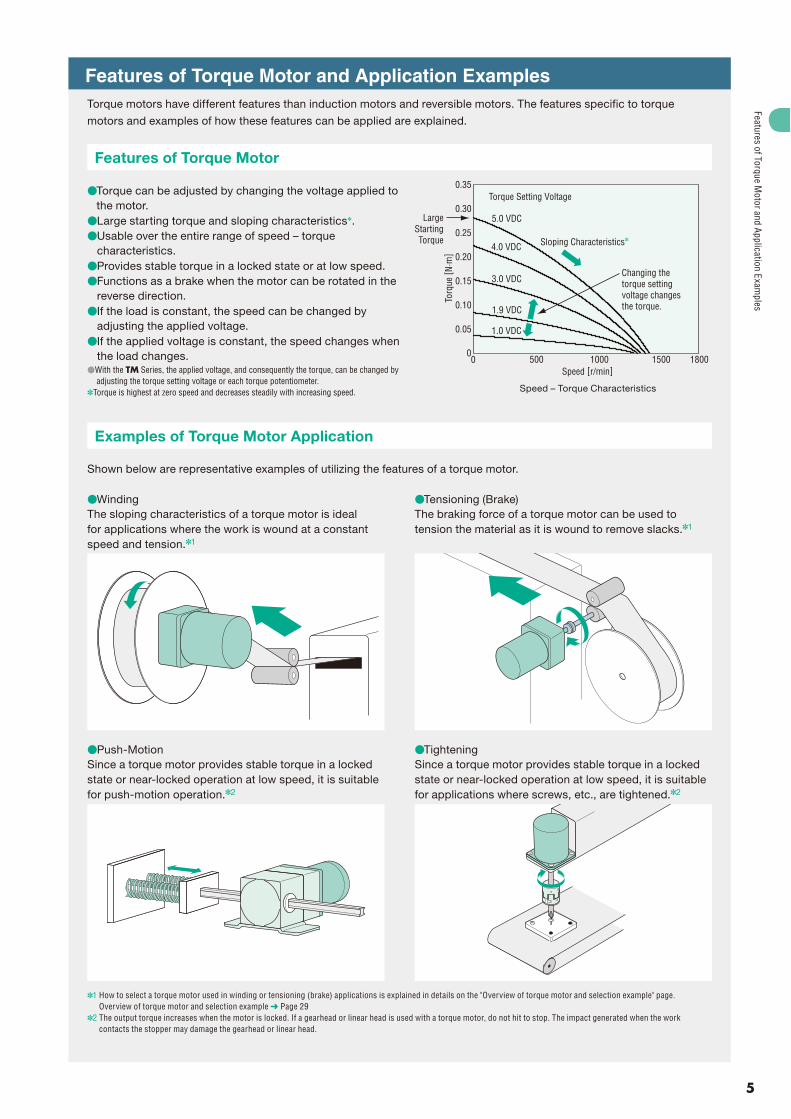
Features of Torque Motor and Application Examples Torque motors have different features than induction motors and reversible motors. The features specific to torque
motors and examples of how these features can be applied are explained.
Features of Torque Motor
�Torque can be adjusted by changing the voltage applied to the motor.
�Large starting torque and sloping characteristics✽.�Usable over the entire range of speed – torque
characteristics.�Provides stable torque in a locked state or at low speed.�Functions as a brake when the motor can be rotated in the
reverse direction. �If the load is constant, the speed can be changed by
adjusting the applied voltage. �If the applied voltage is constant, the speed changes when
the load changes. �With the TM Series, the applied voltage, and consequently the torque, can be changed by
adjusting the torque setting voltage or each torque potentiometer.✽Torque is highest at zero speed and decreases steadily with increasing speed.
Examples of Torque Motor Application
Shown below are representative examples of utilizing the features of a torque motor.
�Winding The sloping characteristics of a torque motor is ideal for applications where the work is wound at a constant speed and tension.✽1
�Push-Motion Since a torque motor provides stable torque in a locked state or near-locked operation at low speed, it is suitable for push-motion operation.✽2
�Tensioning (Brake) The braking force of a torque motor can be used to tension the material as it is wound to remove slacks.✽1
�TighteningSince a torque motor provides stable torque in a locked state or near-locked operation at low speed, it is suitable for applications where screws, etc., are tightened.✽2
✽1 How to select a torque motor used in winding or tensioning (brake) applications is explained in details on the "Overview of torque motor and selection example" page. Overview of torque motor and selection example ➜ Page 29
✽2 The output torque increases when the motor is locked. If a gearhead or linear head is used with a torque motor, do not hit to stop. The impact generated when the work contacts the stopper may damage the gearhead or linear head.
Speed – Torque Characteristics
6
System Configuration
Combination Type, Round Shaft Type
TM Series (Body)
Accessories (Sold separately)
(Not supplied)
Example of System Configuration(Body) (Sold separately)
This potentiometer sets and adjusts the torque of the torque motor (PAVR-20KZ).Dedicated mounting bracket for the motor and gearhead.Clamp type coupling that connects the motor or gearhead shaft to the driven shaft.
Capacitor Cap(Included)
External TorquePotentiometer Mounting Bracket
SOL4M5
Flexible Coupling
MCL301012
Capacitor (Included)
The system configuration shown above is an example. Other combinations are available. Decimal gearheads are also available.
�
�
�System
Configuration
7
Product Number Code
Types of TM SeriesThe TM Series torque motor and power controller packages are available with three different types of motors. All models are combined witha power controller.
�
�
TM 2 03 A - 18 S J � Series TM: TM Series
� Motor Frame Size 2: 60 mm 3: 70 mm4: 80 mm 5: 90 mm
� Output Power (W) (Example) 03: 3 W
� Power Supply Voltage A: Single-Phase 100 VAC, 110/115 VACC: Single-Phase 200 VAC, 220/230 VAC
�Gear Ratio, Motor Shaft Type Number: Gear Ratio for Combination Types
A: Round Shaft TypeGN: GN Type Pinion Shaft
� Type of Gearhead(Combination type only)
S: Long Life, Low Noise GN-S Gearhead, RoHS-Compliant
�Included Capacitor J: For Single-Phase 100 VAC, 200 VAC
U: For Single-Phase 110/115 VACE: For Single-Phase 220/230 VAC
Combination TypeThe pinion shaft motor is pre-assembled with the GN-Sgearhead boasting long life and low noise. A combination type is recommended if you need a gearhead.
The combination type comes with the motor and its dedicated gearhead pre-assembled, which simplifies installation in equipment.The motor and gearhead can be separated with ease.
Pinion Shaft TypeOrder a pinion shaft type in the following cases: · A linear head is combined. · A gearhead is purchased separately.
�
�
�
�
Round Shaft TypeUse a round shaft type if the load is driven directly without using a gearhead.
�
Notes:Use the LS linear head only in push-motion applications. Do not hit to stop.The right-angle gearheads cannot be combined.
�
�
Long Life, Low NoiseGN-S Gearhead
Torque Motor(Pinion shaft)
Power Controller
ADJUST
POWER ALARM
TORQUE
POWER CONTROLLERMODEL TMP-1
Torque Motor(Round shaft)
Power Controller
ADJUST
POWER ALARM
TORQUE
POWER CONTROLLERMODEL TMP-1
Torque Motor(Pinion shaft)
Gearheads/Linear Heads (Sold separately)
Long Life, Low NoiseGN-S Gearhead( Page 8)
LS Linear Head( Page 31)
Power Controller
ADJUST
POWER ALARM
TORQUE
POWER CONTROLLERMODEL TMP-1
System Configuration
8
Product Line
Torque Motor and Power Controller PackageCombination Type
Enter the gear ratio in the box (�) within the model name.
Round Shaft Type
Pinion Shaft TypeGearheads are sold separately.
�
��
�
�
�
The combination type comes with the motor and its dedicated gearhead pre-assembled, which simplifies installation in equipment. Motors and gearheads are also available separately to facilitate changes or repairs.
Combination Type
Output Power Power Supply Voltage Model Gear Ratio
Motor, Gearhead, Power Controller, Capacitor, Capacitor Cap, Mounting Screws, Parallel Key✽, Operating Manual✽Only for the products with a key slot on the output shaft
Gearhead, Mounting Screws, Parallel Key✽, Operating Manual✽Only for the products with a key slot on the output shaft
The following items are included in each product.
Motor, Power Controller, Capacitor, Capacitor Cap, Operating Manual
The following items are included in each product.
Product Line
9
How to Read Speed – Torque CharacteristicsThe TM Series changes its speed – torque characteristics when the value set by the internal or external torque potentiometer or externalDC voltage is changed. An example of characteristics is shown below.
Speed – Torque Characteristics Example) TM410A-AJ
1000500 18001500 Speed [r/min]
Torq
ue [ N
·m]
0
0.30
0.35
0.25
0.20
0.15
0.05
0
0.10
qTorque Setting Voltage
5.0 VDC
100 VAC 50 Hz
4.0 VDC
3.0 VDC
1.9 VDC
1.0 VDC
w
e
�Torque setting voltage The set value when a DC power supply of 0 to 5 VDC is used with the external voltage select switch set to the "5V" position.✽
�Time rating: 5 minutes If the torque setting voltage is 5.0 VDC, the service rating is 5 minutes. The rated time is determined by the permissible temperature of the motor.
�Time rating: ContinuousThe range where the motor can be used continuously. The torque setting voltage that permits continuous motor operation varies from one product to another. Check the specific voltage for each product in the specifications table.
✽If torque is set using a method other than a DC power supply of 0 to 5 VDC, convert the relevant characteristics to torque setting voltages and check them on the characteristics diagram. Use the internal torque potentiometerYou can check the relationship of potentiometer scales and torque setting voltages from the internal torque potentiometer scale – torque setting voltage characteristics on page 26. Use the external torque potentiometerYou can check the relationship of potentiometer scales and torque setting voltages from the external torque potentiometer scale – torque setting voltage characteristics on page 26. Use a DC power supply of 0 to 10 VDC by setting the external voltage select switch to the "10V" positionEach torque setting voltage becomes twice the corresponding voltage when a DC power supply of 0 to 5 VDC is used.
�
�
�
Output Torque of Combination TypeDue to the sloping characteristics, torque motors can be operated over a wide speed range, from standstill to the maximum speed. The output torque of the combination type can be calculated according to the following formulas, using the speed and torque determined from the speed – torque characteristics.
Output shaft speed of combination type NG = Motor speed�1/gearhead gear ratioOutput torque of combination type TG = Motor torque�Gearhead gear ratio�Gearhead efficiency
The output torque of combination type must be lower than the maximum permissible torque.
50 100 150 200
10
5
Gear Ratio
Maximum Permissible Torque of Combination Type
0
TM520
TM410
TM306
TM203
Torq
ue [ N
·m]
Gearhead Gear Ratio Gearhead Efficiency
3, 3.6, 5, 6, 7.5, 9, 12.5, 15, 18 81%
25, 30, 36 73%
50, 60, 75, 90, 100, 120, 150, 180 66%
How to Use Reverse-Phase BrakeThe TM Series motor operates at a speed balanced with the load according to the motor's speed – torque characteristics, when not receiving a force that rotates it in the reverse direction. If the TM Series motor is to be used as a reverse-phase motor, rotate the motor in the reverse direction using a torque greater than the motor starting torque. As the torque motor rotates in the reverse direction, it generates a certain level of braking force. Fig. 1 shows an example of speed – brake torque characteristics in a reverse-phase brake application. In a reverse-phase brake application, a large braking force can be obtained right from 0 r/min. This feature is suitable for applications where tension must be applied even when the motor is at standstill.
�5.0 VDC
4.0 VDC
1.9 VDC
1.0 VDC0.05
0.15
0.10
0.25
0.20
0.35
0.30
TM410A-AJ
500 1000 1500 Speed [r/min]
Brak
e To
rque
[ N·m
]
Torque Setting Voltage
3.0 VDC
00
Fig. 1Example of Speed – Brake Torque Characteristics with
Reverse-Phase Brake (Reference values)
�
�
Specifications and Characteristics
10
Torque Motor and Power Controller Package TM Series
3 W�60 mm
Specifications Motor: Power Controller:
✽The torque setting voltage indicates the value when the external voltage select switch is set to the "5V" position. The values for the combination type apply to the motor only.Enter the gear ratio in the box (�) within the model name.
: Contains a built-in thermal protector (automatic return type). If a motor overheats for any reason, the thermal protector is activated and the motor is stopped.
Output Torque of Combination TypeDue to the sloping characteristics, torque motors can be operated over a wide speed range, from standstill to the maximum speed. The output torque of the combination type can be calculated according to the following formulas, using the speed and torque determined from the speed – torque characteristics.
Output shaft speed of combination type NG = Motor speed�1/gearhead gear ratioOutput torque of combination type TG = Motor torque�Gearhead gear ratio�Gearhead efficiency
The output torque of combination type must be lower than the maximum permissible torque.Maximum permissible torque of combination type ➜ Page 9
Gearhead Gear Ratio Gearhead Efficiency
3, 3.6, 5, 6, 7.5, 9, 12.5, 15, 18 81%
25, 30, 36 73%
50, 60, 75, 90, 100, 120, 150, 180 66%
Starting torque of combination type ➜ Page 19
Speed – Torque Characteristics (Reference values)The torque setting voltage indicates the value when the external voltage select switch is set to the "5V" position.The values for the combination type apply to the motor only.
Torque Motor and Power Controller Package TM Series
6 W�70 mm
Specifications Motor: Power Controller:
✽The torque setting voltage indicates the value when the external voltage select switch is set to the "5V" position. The values for the combination type apply to the motor only.Enter the gear ratio in the box (�) within the model name.
: Contains a built-in thermal protector (automatic return type). If a motor overheats for any reason, the thermal protector is activated and the motor is stopped.
Output Torque of Combination TypeDue to the sloping characteristics, torque motors can be operated over a wide speed range, from standstill to the maximum speed. The output torque of the combination type can be calculated according to the following formulas, using the speed and torque determined from the speed – torque characteristics.
Output shaft speed of combination type NG = Motor speed�1/gearhead gear ratioOutput torque of combination type TG = Motor torque�Gearhead gear ratio�Gearhead efficiency
The output torque of combination type must be lower than the maximum permissible torque.Maximum permissible torque of combination type ➜ Page 9
Gearhead Gear Ratio Gearhead Efficiency
3, 3.6, 5, 6, 7.5, 9, 12.5, 15, 18 81%
25, 30, 36 73%
50, 60, 75, 90, 100, 120, 150, 180 66%
Starting torque of combination type ➜ Page 19
Speed – Torque Characteristics (Reference values)The torque setting voltage indicates the value when the external voltage select switch is set to the "5V" position.The values for the combination type apply to the motor only.
Torque Motor and Power Controller Package TM Series
10 W�80 mm
Specifications Motor: Power Controller:
✽The torque setting voltage indicates the value when the external voltage select switch is set to the "5V" position. The values for the combination type apply to the motor only.Enter the gear ratio in the box (�) within the model name.
: Contains a built-in thermal protector (automatic return type). If a motor overheats for any reason, the thermal protector is activated and the motor is stopped.
Output Torque of Combination TypeDue to the sloping characteristics, torque motors can be operated over a wide speed range, from standstill to the maximum speed. The output torque of the combination type can be calculated according to the following formulas, using the speed and torque determined from the speed – torque characteristics.
Output shaft speed of combination type NG = Motor speed�1/gearhead gear ratioOutput torque of combination type TG = Motor torque�Gearhead gear ratio�Gearhead efficiency
The output torque of combination type must be lower than the maximum permissible torque.Maximum permissible torque of combination type ➜ Page 9
Gearhead Gear Ratio Gearhead Efficiency
3, 3.6, 5, 6, 7.5, 9, 12.5, 15, 18 81%
25, 30, 36 73%
50, 60, 75, 90, 100, 120, 150, 180 66%
Starting torque of combination type ➜ Page 19
Speed – Torque Characteristics (Reference values)The torque setting voltage indicates the value when the external voltage select switch is set to the "5V" position.The values for the combination type apply to the motor only.
Torque Motor and Power Controller Package TM Series
20 W�90 mm
Specifications Motor: Power Controller:
✽The torque setting voltage indicates the value when the external voltage select switch is set to the "5V" position. The values for the combination type apply to the motor only.Enter the gear ratio in the box (�) within the model name.
: Contains a built-in thermal protector (automatic return type). If a motor overheats for any reason, the thermal protector is activated and the motor is stopped.
Output Torque of Combination TypeDue to the sloping characteristics, torque motors can be operated over a wide speed range, from standstill to the maximum speed. The output torque of the combination type can be calculated according to the following formulas, using the speed and torque determined from the speed – torque characteristics.
Output shaft speed of combination type NG = Motor speed�1/gearhead gear ratioOutput torque of combination type TG = Motor torque�Gearhead gear ratio�Gearhead efficiency
The output torque of combination type must be lower than the maximum permissible torque.Maximum permissible torque of combination type ➜ Page 9
Gearhead Gear Ratio Gearhead Efficiency
3, 3.6, 5, 6, 7.5, 9, 12.5, 15, 18 81%
25, 30, 36 73%
50, 60, 75, 90, 100, 120, 150, 180 66%
Starting torque of combination type ➜ Page 19
Speed – Torque Characteristics (Reference values)The torque setting voltage indicates the value when the external voltage select switch is set to the "5V" position.The values for the combination type apply to the motor only.
� Setting by the internal torque potentiometer (TORQUE)� Setting by an accessory external torque potentiometer (sold separately): PAVR-20KZ (20 k , 1/4 W)� Setting by external DC voltage: 0�5 VDC or 0�10 VDC, 1 mA or moreFine-tuning by the torque fi ne-tuning potentiometer (ADJUST) is possible.
Output Signal Open-collector output: 4.5�26.4 VDC, 40 mA or lessAlarm output
Protective FunctionWhen in the following conditions, the motor stops, the alarm LED blinks and alarm signal is output.� The thermal protector built-in to the motor is activated (open)� There is improper connection/disconnection of the power supply cable and motor cable
Maximum Extension Distance 20 m between motor and power controller
General SpecificationsItem Motor Power Controller
Insulation Resistance100 M or more when 500 VDC megger is applied between the windings and the case after rated motor operation under normal ambient temperature and humidity.
100 M or more when 500 VDC megger is applied between the main circuit terminal and the control circuit terminal, between the main circuit terminal and the case after continuous operation under normal ambient temperature and humidity.
Dielectric StrengthSuffi cient to withstand 1.5 kV at 50 Hz or 60 Hz applied between the windings and the case for 1 minute after rated operation under normal ambient temperature and humidity.
Suffi cient to withstand 3 kV at 50 Hz or 60 Hz applied between the main circuit terminal and the control circuit terminal, between the main circuit terminal and the case for 1 minute after continuous operation under normal ambient temperature and humidity.
Temperature Rise
Temperature rise of windings are 80˚C or less (single-phase 100 VAC, single-phase 200 VAC) measured by the resistance change method after rated operation under normal ambient temperature and humidity with connecting a gearhead or equivalent heat radiation plate✽.All others: 90˚C or less
—
Overheat Protection Device
Built-in thermal protector (automatic return type)3 W type open: 130�5˚C, close: 90�15˚COther type open: 130�5˚C, close: 82�15˚C
Ambient Humidity 85% or less (non-condensing)Insulation Class Class B (130˚C) —Degree of Protection IP20 IP20
✽Heat radiation plate (Material: aluminum)
Motor Type (Output power) Size (mm) Thickness (mm)TM203 type (3 W) 115�115
5TM306 type (6 W) 125�125TM410 type (10 W) 135�135TM520 type (20 W) 165�165
Note:Do not measure insulation resistance or perform the dielectric strength test while the motor and power controller are connected.
Safety Standards and CE MarkingMotor
Standards Certifi cation Body Standards File No. CE MarkingUL 1004UL 2111
UL E64197
Low Voltage Directives
CSA C22.2 No.100CSA C22.2 No.77
EN 60950-1EN 60034-1EN 60034-5IEC 60664-1
Conform to EN/IEC Standards
GB 12350 CQC 2005010401150784
When the motor is approved under various safety standards, the model name on the motor nameplate is the approved model name. The J, U and E at the end of the model name indicate that the unit includes a capacitor. These letters are not listed on the motor nameplate.
Power ControllerStandards Certifi cation Body Standards File No. CE Marking
UL 508 UL E91291 Low Voltage Directives
EMC DirectivesEN 50178EN 60950-1 Conform to EN Standards
The EMC value changes according to the wiring and layout. Therefore, the final EMC level must be checked with the motor/power controller incorporated in the user's equipment.
�
�
�
��
�
�
�
Specifications and Characteristics
19
Starting Torque of Combination TypeWith torque motors having sloping characteristics, the greatest torque is generated when the motor is started. The table below lists the starting torques of combination types. The output torques in conditions other than at start can be obtained by the formula explained under "Output Torque of Combination Type."Output torque of combination type ➜ Page 9A colored background ( ) indicates gear shaft rotation in the same direction as the motor shaft, while the others rotate in the
opposite direction.To reduce the speed beyond the gear ratio in the table, attach a decimal gearhead of gear ratio 1/10 (sold separately) between thegearhead and the motor. In that case, the permissible torques are as follows.TM203: 3 N�m, TM306: 5 N�m, TM410: 8 N�m (When a gearhead of 1/25 to 1/36 is connected, the value for permissible torque is 6 N�m.), TM520: 10 N�mEnter the gear ratio in the box (�) within the model name.
�Shaft Section of Round Shaft TypeThe motor's dimensions (excluding the shaft section) are the same
as those of the combination types.TM203A-A�� , TM203C-A��
Motor: 2TK3A-AW2�� , 2TK3A-CW2��
Mass: 0.7 kg
6 W�Combination Type
��
�
�
Model Motor Model Gearhead Model Gear Ratio L Mass (kg)TM203A-�S�� 2TK3GN-AW2��
2GN�S3�18 30
1.1TM203C-�S�� 2TK3GN-CW2�� 25�180 40
4��4.5 Thru
Motor Leads 300 mm LengthUL Style 3266, AWG20
75 L 325
10
12
�24
60
�60
7
7 70�0.5
22.5
60
�8
�0.
015 (
h7)
0
5 max.
Protective Earth TerminalM4
15.5
21.5
Detail Drawing of Protective Earth Terminal
Protective Earth TerminalM4
Decimal GearheadCan be connected to TM203 pinion shaft type.2GN10XSMass: 0.2 kg
�
224
22.5
70�0.5
�60
�54
�0.
030 (
h7)
0
�6
�0.
012 (
h7)
0
5 max.
Protective Earth TerminalM4
4��4.5 Thru
38.526 12.5
2
70�0.5
�60
�54
�0.
030 (
h7)
04��4.5 Thru
Model Motor Model Gearhead Model Gear Ratio L Mass (kg)TM306A-�S�� 3TK6GN-AW2��
3GN�S3�18 32
1.65TM306C-�S�� 3TK6GN-CW2�� 25�180 42
Key and Key Slot (Included)�
25 0.2 4 00.040
2.5
00.1
40.
03 0
4 0.03 0
�69
807
L 325
25
15 �30
82�0.5
Motor Leads 300 mm LengthUL Style 3271, AWG20
70
70
22.5
�10
�0.
015 (
h7)
0
5 max.
Protective Earth TerminalM4
4��5.5 Thru
16.5
21.5
Detail Drawing of Protective Earth Terminal
Protective Earth TerminalM4
Enter the gear ratio in the box (�) within the model name.Enter J, U or E (included capacitor) in the box (��) within the model name.
�
Dim
ensions
21
�Shaft Section of Round Shaft TypeThe motor's dimensions (excluding the shaft section) are the same
as those of the combination types.TM306A-A�� , TM306C-A��
Motor: 3TK6A-AW2�� , 3TK6A-CW2��
Mass: 1.1 kg
10 W�Combination Type
�Shaft Section of Round Shaft TypeThe motor's dimensions (excluding the shaft section) are the same
as those of the combination types.TM410A-A�� , TM410C-A��
Motor: 4TK10A-AW2�� , 4TK10A-CW2��
Mass: 1.5 kg
�
Decimal GearheadCan be connected to TM306 pinion shaft type.3GN10XSMass: 0.3 kg
�
232
82�0.5
�70
22.5
�64
�0.
030 (
h7)
0�
6�0.
012 (
h7)
0
5 max.
Protective Earth TerminalM4
4��5.5 Thru
4330 13
2
82�0.5
�64
�0.
030 (
h7)
0 �70
4��5.5 Thru
Model Motor Model Gearhead Model Gear Ratio L Mass (kg)TM410A-�S�� 4TK10GN-AW2��
4GN�S3�18 32
2.15TM410C-�S�� 4TK10GN-CW2�� 25�180 42.5
Key and Key Slot (Included)�
25 0.2 4 00.040
2.5
00.1
40.
03 0
4 0.03 0
�79
L85 326
94�0.5
7
25
�34
15
80
UL Style 3271, AWG20
80
22.5
�10
�0.
015 (
h7)
0
5 max.
Protective Earth TerminalM4
4��5.5 Thru
Motor Leads 300 mm Length
16.5
21.5
Detail Drawing of Protective Earth Terminal
Protective Earth TerminalM4
4��5.5 Thru232
94�0.525
7
�80
22.5
�73
�0.
030 (
h7)
0
�8�
0.01
5 (h7
)0
5 max.
Protective Earth TerminalM4
Decimal GearheadCan be connected to TM410 pinion shaft type.4GN10XSMass: 0.4 kg
�
45.532 13.5
2
�80
4��5.5 Thru
94�0.5
�73
�0.
030 (
h7)
0
Enter the gear ratio in the box (�) within the model name.Enter J, U or E (included capacitor) in the box (��) within the model name.
�
Dim
ensions
22
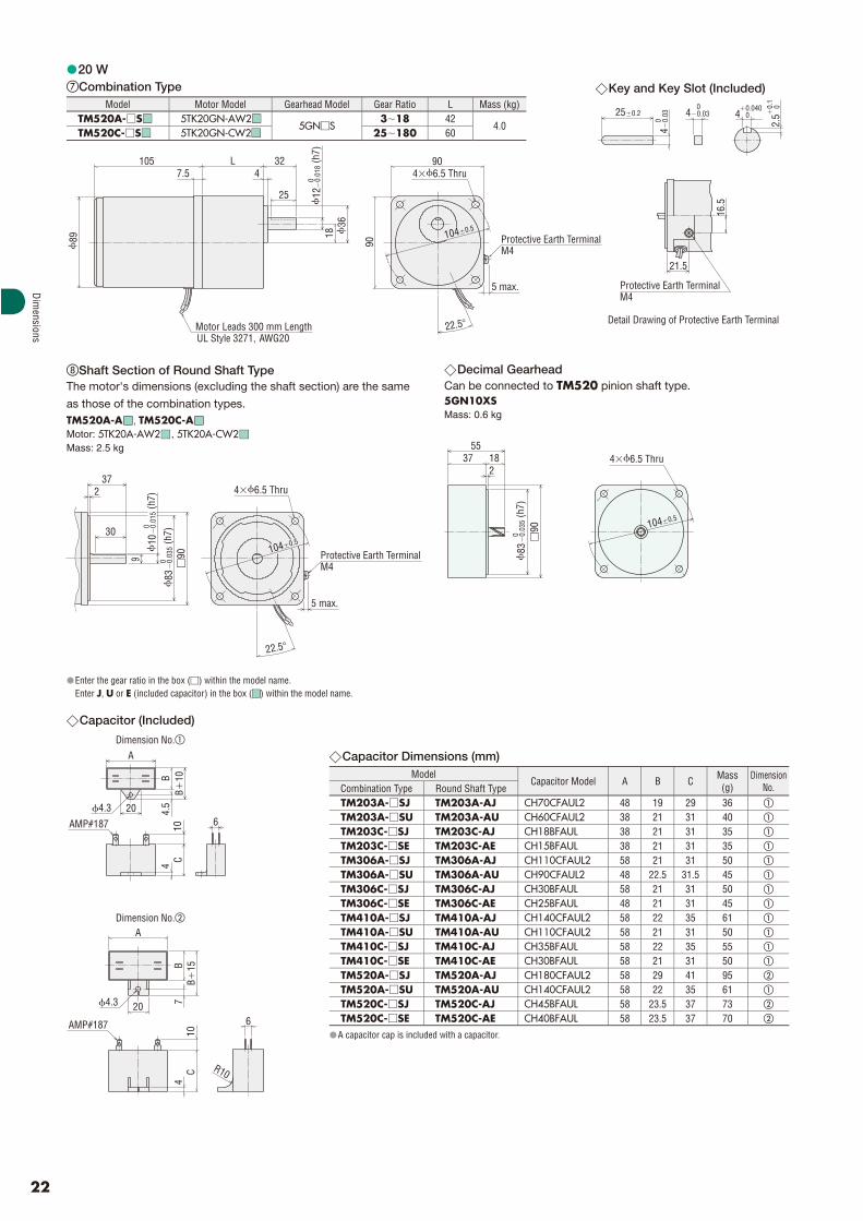
Capacitor Dimensions (mm) Model
Capacitor Model A B C Mass(g)
DimensionNo.Combination Type Round Shaft Type
TM203A-�SJ TM203A-AJ CH70CFAUL2 48 19 29 36 �
TM203A-�SU TM203A-AU CH60CFAUL2 38 21 31 40 �
TM203C-�SJ TM203C-AJ CH18BFAUL 38 21 31 35 �
TM203C-�SE TM203C-AE CH15BFAUL 38 21 31 35 �
TM306A-�SJ TM306A-AJ CH110CFAUL2 58 21 31 50 �
TM306A-�SU TM306A-AU CH90CFAUL2 48 22.5 31.5 45 �
TM306C-�SJ TM306C-AJ CH30BFAUL 58 21 31 50 �
TM306C-�SE TM306C-AE CH25BFAUL 48 21 31 45 �
TM410A-�SJ TM410A-AJ CH140CFAUL2 58 22 35 61 �
TM410A-�SU TM410A-AU CH110CFAUL2 58 21 31 50 �
TM410C-�SJ TM410C-AJ CH35BFAUL 58 22 35 55 �
TM410C-�SE TM410C-AE CH30BFAUL 58 21 31 50 �
TM520A-�SJ TM520A-AJ CH180CFAUL2 58 29 41 95 �
TM520A-�SU TM520A-AU CH140CFAUL2 58 22 35 61 �
TM520C-�SJ TM520C-AJ CH45BFAUL 58 23.5 37 73 �
TM520C-�SE TM520C-AE CH40BFAUL 58 23.5 37 70 �
A capacitor cap is included with a capacitor.
�
�
20 W�Combination Type
Shaft Section of Round Shaft TypeThe motor's dimensions (excluding the shaft section) are the same
as those of the combination types.TM520A-A�� , TM520C-A��
Motor: 5TK20A-AW2�� , 5TK20A-CW2��
Mass: 2.5 kg
Enter the gear ratio in the box (�) within the model name.Enter J, U or E (included capacitor) in the box (��) within the model name.
Capacitor (Included)
Dimension No.�
Dimension No.�
�
�
�
4��6.5 Thru
�89
105 L4
327.5
18 �36
25
90
Motor Leads 300 mm LengthUL Style 3271, AWG20
104�0.5
90
22.5�
12�
0.01
8 (h7
)0
5 max.
Protective Earth TerminalM4
Model Motor Model Gearhead Model Gear Ratio L Mass (kg)TM520A-�S�� 5TK20GN-AW2��
5GN�S3�18 42
4.0TM520C-�S�� 5TK20GN-CW2�� 25�180 60
Key and Key Slot (Included)�
25 0.2 4 00.040
2.5
00.1
40.
03 0
4 0.03 0
16.5
21.5
Detail Drawing of Protective Earth Terminal
Protective Earth TerminalM4
Decimal GearheadCan be connected to TM520 pinion shaft type.5GN10XSMass: 0.6 kg
�
237
30
9
4��6.5 Thru
104�0.5
�90
22.5
�10
�0.
015 (
h7)
0
�83
�0.
035 (
h7)
0
5 max.
Protective Earth TerminalM4
37 1855
2
�90
4��6.5 Thru
104�0.5�
83�
0.03
5 (h7
)0
4.3 20
A
CB
10B4.
54
10 6AMP#187
6
A
CB
720
10
AMP#187
4.3
4B
15
R10
Dim
ensions
23
Power ControllerTMP-1 Mass: 0.18 kg
�
16.83.5
9
5511
2 m
ax.
100
45
65
2��5
Connection and OperationNames and Function of Power Controller Parts
An external power supply of 24 VDC is required.
��
No. Name Description
zInternal torque potentiometer (TORQUE) Sets the motor torque.
xTorque fi ne-tuning potentiometer (ADJUST)
Fine-tunes the variation in the motor torque with respect to the set torque.
cSink/source input select switch
Switches between the sink logic and source logic for the input circuit.
vExternal voltage select switch
Switches between 5 V and 10 V according to the external DC power supply used when external DC voltage is used to set torque.
b POWER LED (green) Lights while the AC power is supplied to the power controller.
n ALARM LED (red) Blinks while an alarm is present. (The alarm output turns OFF.)
mMain Circuit Terminal
Terminal No. Terminal Name Name Description 1 N AC power supply
connection terminalConnects the AC power supply. N: Neutral, L: Live2 L
3CAPACITOR Capacitor connection terminal Connects the capacitor.
45 BLK
Motor connection terminal Connects the motor. BLK: Black, RED: Red, WHT: White 6 RED
7 WHT
,Control Circuit Terminal
Terminal Name Name Description 24V �DC24V
Connects the 24-VDC power for control circuit. 0V 0VX0 CW input These inputs control the rotation direction and RUN/STOP mode of
the motor. If both inputs turn ON simultaneously, the motor stops. X1 CCW inputX2 INT/EXT switch input Switches between the internal and external torque settings.X3 Alarm reset input Resets alarms.
C1 IN-COM0The polarity changes depending on whether the sink or source logic is applied. (Sink: 0 V, Source: 24 V)
Y0 Alarm output These terminals output an alarm signal. Once generated, alarms will not be cleared unless reset. (4.5 to 26.4 VDC, 40 mA or less) C0 OUT-COM
VH VH inputThese inputs allow torque to be set using the external torque potentiometer or external DC voltage. VM VM input
VL VL input
C2IN-COM1
If an external power supply is used by applying the source logic, connect these terminals to the GND line of the external power supply. (Input signal common: 0 V) C3
zx
c
v
b
n
,
m
Connection and Operation
24
Connection DiagramsThe connection diagram is for when the SINK/SOURCE select switch is set to the "SOURCE" side.
✽1 Input signals X0 to X3 and C1 assume the sequence connection using mechanical contacts or sink transistor. Also note that the mechanical contacts, sink transistor or any other device connected to input signals X0 to X3 should have a leak current of 1 mA or less.
✽2 The control circuit is a SELV circuit. It is isolated from dangerous voltages by means of protective isolation based on reinforced insulation. The power supply and other devices connected to the control circuit terminals should be isolated from dangerous voltages by reinforced insulation.
✽1 After turning on the AC power and 24 VDC power, wait at least 100 ms before turning ON the CW input or CCW input. The AC power and 24 VDC power can be turned on in any order.
✽2 If the CW input and CCW input are turned ON simultaneously, the motor will stop. ✽3 Whether to use the internal torque potentiometer or external torque potentiometer
can be changed by the INT/EXT input signal.
�
�
Applicable Crimp Terminals� Main Circuit Connection Terminal (M3.5)Round Terminal with Insulation
3.9 mm max.
7.8 mm max.
�3.6 mm min.
� Control Circuit Connection Terminal
When a crimp terminal is used for connection, use such terminals as shown below.A crimp terminal used varies with the size of wire. Also, applicable wire size when the terminals below are used is AWG20 to 18.
I/O Signal ConnectionTorque Setting Using an External Torque Potentiometer or ExternalDC Voltage
C3C2
0 V
+5 V
0V
24V24 VDC�10%100 mA or more
4
3CAPACITOR Capacitor
100-115 VACor
200-230 VAC Motor
✽
✽Current Limiting Resistor
Connection and Operation
25
I/O Signal CircuitThe factory setting is the source logic. Select the sink logic or source logic according to the external control device you will be using.
Input Signal CircuitCommon to CW, CCW, INT/EXT switch and Alarm reset
� Source Logic
4.7 k
0 V
Input Circuit
C1+24 V
IN-COM0
CWCCW
INT/EXT SwitchAlarm Reset
X0X1X2X3
Power Controller
or
4.7 k
0 V
Input Circuit
C2C3 0 V
24 VDC,10 mA or more
Power Controller
IN-COM1
CWCCW
INT/EXT SwitchAlarm Reset
X0X1X2X3
� Sink Logic
Input Common
4.7 k
+24 V
0 V
CWCCW
INT/EXT SwitchAlarm Reset
X0X1X2X3
C1
Input Circuit
Power Controller
�
�
Output Signal CircuitALARM output
� Source Logic4.5 to 26.4 VDC,5 to 40 mA or less
✽Recommended Resistance• 24 VDC
680 to 4.7 k (2 W)• 5 VDC
150 to 1.0 k (0.5 W)
Y0
0 V
C0
Power Controller
Y0: ALARM Output
Shielded Wire
Insert a current limiting resistor to keep the current to 40 mA or less.✽
� Sink Logic
Y0: ALARM Output
C00 V
Y0
Power ControllerShielded Wire
4.5 to 26.4 VDC,5 to 40 mA or less
✽Recommended Resistance• 24 VDC
680 to 4.7 k (2 W)• 5 VDC
150 to 1.0 k (0.5 W)
Insert a current limiting resistor to keep the current to 40 mA or less.✽
When an External Control Device with a Built-In Clamp Diode is Used
When an external control device with a built-in clamp diode is used, if the power is being supplied to the power controller, current may flow and cause the motor to run, even if the power supply of the external control device is off. Because the power capacity differs, the motor may also run when the power supplies are turned on/off simultaneously. Turn on the power of the external control device before the power controller. Turn off the power of the power controller before the external control device.
� Example of Sink Logic
External Control Device Power Controller
X0 to X3
C1
+24 V
0 V
0 V
+Vcc
Clamp Diode
�
�
Connection and Operation
26
Operating MethodThe RUN/STOP mode and rotation direction of the motor are
changed using the CW or CCW input. When the CW input is
turned "ON," the motor will rotate clockwise as viewed from the
output shaft of the motor. When the CCW input is turned "ON,"
the motor will rotate counterclockwise as viewed from the output
shaft of the motor. If the CW input and CCW input are turned "ON"
simultaneously, the motor will stop.
CW Input CCW Input Motor OperationON OFF Run (Clockwise)OFF ON Run (Counterclockwise)ON ON StopOFF OFF Stop
Torque Setting Method Torque is set using the internal torque potentiometer, accessory external torque potentiometer (PAVR-20KZ) or external DC voltage.
Setting by Internal Torque PotentiometerWhen the INT/EXT switch input is "OFF," motor torque can be adjusted using the internal torque potentiometer. The relationship of internal torque potentiometer scale – torque characteristics (representative values) can be checked as follows: �Using the graph below, check the torque setting voltage
corresponding to each scale on the internal torque potentiometer.
�Based on the torque setting voltage✽1, check the corresponding motor torque from the speed – torque characteristics✽2.
✽1 The value when the external voltage select switch is set to the "5V" position. ✽2 Featured on the specifications pages of respective products.
➜ Pages 10, 12, 14 and 16 5
4
3
2
1
0 2 4 6 8 10Internal Torque Potentiometer Scale
Internal Torque Potentiometer Scale �Torque Setting Voltage Characteristics (Representative values)
Tor
que
Setti
ng V
olta
ge [V
DC]
+
100
TORQUE
Internal Torque Potentiometer(No numbers are indicated onthe actual unit.)
�
�
�
Setting by External Torque Potentiometer When the INT/EXT switch input is "ON," motor torque can be adjusted using the accessory external torque potentiometer (PAVR-20KZ). Connect the external torque potentiometer as follows.
The relationship of external torque potentiometer scale – torque characteristics (representative values) can be checked as follows: �Using the graph below, check the torque setting voltage
corresponding to each scale on the external torque potentiometer. �Based on the torque setting voltage✽1, check the corresponding
motor torque from the speed – torque characteristics✽2.✽1 The value when the external voltage select switch is set to the "5V" position.✽2 Featured on the specifications pages of respective products.
Setting by External DC Voltage Set the external voltage select switch on the power controller according to 5 VDC or 10 VDC input from the external DC power supply used. The switch is set to the "5V" position at the factory. The INT/EXT switch input should be "ON."
MOTOR
100-230V� CAPACITOR
BLK RED WHT1 2 3 4
5 6 7
LN
SOURCE SINK
5V10V
Y0 C0 VH VM VL C2 C324V 0V X0 X1 X2 X3 C1
�: To VM Input
�: To VL Input
External DC Power Supply
0 to 5 VDC or 0 to 10 VDC 1 mA or more
Shielded Wire
10V 5V
Set the external voltageselect switch
The torque setting voltages of respective products in the specifications tables and speed – torque characteristics are values when the external voltage select switch is set to the "5V" position. If the external voltage select switch is set to the "10V" position, each torque setting voltage becomes twice the corresponding value at 5 VDC.
�
�
Connection and Operation
27
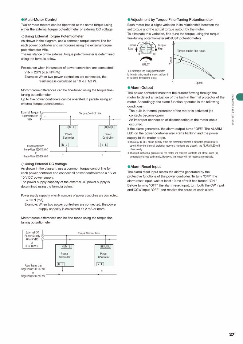
Multi-Motor ControlTwo or more motors can be operated at the same torque using either the external torque potentiometer or external DC voltage.
Using External Torque PotentiometerAs shown in the diagram, use a common torque control line for each power controller and set torques using the external torque potentiometer VRx.The resistance of the external torque potentiometer is determined using the formula below.
Resistance when N numbers of power controllers are connected: VRx = 20/N (kΩ), N/4 (W) Example: When two power controllers are connected, the
resistance is calculated as 10 kΩ, 1/2 W.
Motor torque differences can be fine-tuned using the torque fine-tuning potentiometer. Up to five power controllers can be operated in parallel using an external torque potentiometer.
External TorquePotentiometer
VRx
321
PowerController
PowerController
Power Supply LineSingle-Phase 100-115 VAC
orSingle-Phase 200-230 VAC
Torque Control Line
H M L
N L
H M L
N L
Using External DC VoltageAs shown in the diagram, use a common torque control line for each power controller and connect all power controllers to a 5 V or 10 V DC power supply.The power supply capacity of the external DC power supply is determined using the formula below:
Power supply capacity when N numbers of power controllers are connected:I = 1�N (mA)
Example: When two power controllers are connected, the power supply capacity is calculated as 2 mA or more.
Motor torque differences can be fine-tuned using the torque fine-tuning potentiometer.
Torque Control LineExternal DCPower Supply
0 to 5 VDCor
0 to 10 VDC
Power Supply LineSingle-Phase 100-115 VAC
orSingle-Phase 200-230 VAC
�
�
H M L
PowerController
N L
H M L
PowerController
N L
�
�
�
Adjustment by Torque Fine-Tuning Potentiometer Each motor has a slight variation in its relationship between the set torque and the actual torque output by the motor. To eliminate this variation, fine-tune the torque using the torque fine-tuning potentiometer (ADJUST potentiometer).
+ ADJUST
100
TorqueLow
TorqueHigh
Turn the torque fine-tuning potentiometerto the right to increase the torque, and turn itto the left to decrease the torque.
Torq
ue
0
Torque can be fine-tuned.
Speed
Alarm Output The power controller monitors the current flowing through the motor to detect an actuation of the built-in thermal protector of the motor. Accordingly, the alarm function operates in the following conditions:· The built-in thermal protector of the motor is activated (its
contacts became open). · An improper connection or disconnection of the motor cable
occurred. If the alarm generates, the alarm output turns "OFF." The ALARM LED on the power controller also starts blinking and the power supply to the motor stops.
The ALARM LED blinks quickly while the thermal protector is activated (contacts are open). Once the thermal protector recovers (contacts are closed), the ALARM LED will blink slowly. The built-in thermal protector of the motor will recover (contacts will close) once the temperature drops sufficiently. However, the motor will not restart automatically.
Alarm Reset Input The alarm reset input resets the alarms generated by the protective functions of the power controller. To turn "OFF" the alarm reset input, wait at least 10 ms after it has turned "ON." Before turning "OFF" the alarm reset input, turn both the CW input and CCW input "OFF" and resolve the cause of each alarm.
�
�
�
�
�
Connection and Operation
28
List of Motor and Power Controller CombinationsCombination Type
The combination type comes with the motor and parallel shaft gearhead pre-assembled.
Enter the gear ratio in the box (�) within the model name.
Round Shaft Type
Pinion Shaft Type
��
�
�
�
Output Power Model Motor Model Gearhead Model Power Controller Model
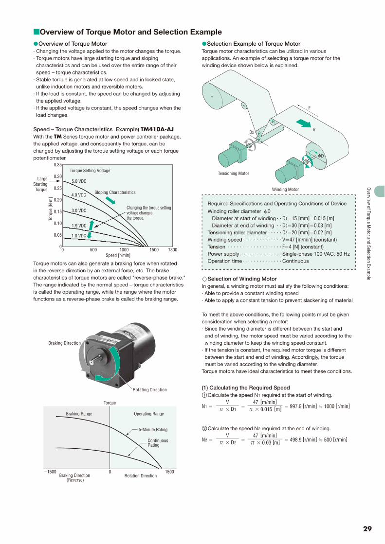
Overview of Torque Motor and Selection Example �Overview of Torque Motor
· Changing the voltage applied to the motor changes the torque. · Torque motors have large starting torque and sloping
characteristics and can be used over the entire range of their speed – torque characteristics.
· Stable torque is generated at low speed and in locked state, unlike induction motors and reversible motors.
· If the load is constant, the speed can be changed by adjusting the applied voltage.
· If the applied voltage is constant, the speed changes when the load changes.
Speed – Torque Characteristics Example) TM410A-AJWith the TM Series torque motor and power controller package, the applied voltage, and consequently the torque, can be changed by adjusting the torque setting voltage or each torque potentiometer.
1000500 18001500Speed [r/min]
Torq
ue [N
·m]
0
0.30
0.35
0.25
0.20
0.15
0.05
0
0.10
5.0 VDC
4.0 VDC
3.0 VDC
1.9 VDC
1.0 VDC
LargeStartingTorque
Torque Setting Voltage
Sloping Characteristics
Changing the torque setting voltage changesthe torque.
Torque motors can also generate a braking force when rotated in the reverse direction by an external force, etc. The brake characteristics of torque motors are called "reverse-phase brake." The range indicated by the normal speed – torque characteristics is called the operating range, while the range where the motor functions as a reverse-phase brake is called the braking range.
Braking Direction
Rotating Direction
1500�1500 0
Torque
Braking Range Operating Range
5-Minute Rating
ContinuousRating
Braking Direction (Reverse)
Rotation Direction
� Selection Example of Torque Motor Torque motor characteristics can be utilized in various applications. An example of selecting a torque motor for the winding device shown below is explained.
�D
V
F
D3
Tensioning Motor
Winding Motor
Required Specifications and Operating Conditions of Device
Selection of Winding Motor In general, a winding motor must satisfy the following conditions: · Able to provide a constant winding speed · Able to apply a constant tension to prevent slackening of material
To meet the above conditions, the following points must be given consideration when selecting a motor:· Since the winding diameter is different between the start and
end of winding, the motor speed must be varied according to the winding diameter to keep the winding speed constant.
· If the tension is constant, the required motor torque is different between the start and end of winding. Accordingly, the torque must be varied according to the winding diameter.
Torque motors have ideal characteristics to meet these conditions.
(1) Calculating the Required Speed � Calculate the speed N1 required at the start of winding.
(2) Calculating the Required Torque� Calculate the torque T1 required at the start of winding.
T1 �F�D1
2 �4 [N] �0.015 [m]
2 � 0.03 [N�m]
� Calculate the torque T2 required at the end of winding.
T2 �F�D2
2 �4 [N] �0.03 [m]
2 � 0.06 [N�m]
This winding motor must meet the following conditions: Start of winding:
Speed N1 � 1000 [r/min], Torque T1 � 0.03 [N�m] End of winding:
Speed N2 � 500 [r/min], Torque T2 � 0.06 [N�m]
(3) Selecting a Motor � Check the speed – torque characteristics Select from the TM Series torque motor and power controller package a motor meeting the required conditions specified above. Plot the required conditions on the speed – torque characteristics diagram of the TM410A-AJ, and it is clear that the conditions roughly correspond to the characteristics at a torque setting voltage of 1.9 VDC.
� Check the operation timeThe TM410A-AJ has a 5-minute rating when the torque setting voltage is set to 5.0 VDC, and continuous rating when it is set to 1.9 VDC. Under the conditions given here, the torque setting voltage is 1.9 VDC or less, meaning that this motor can be operated continuously.
Note:If a torque motor is operated continuously in a winding application, select conditions where the service rating of the torque motor remains continuous.
�
Selection of Tensioning MotorIf tension is not applied, the material slackens as it is wound or otherwise the material cannot be wound neatly. Torque motors also have reverse-phase brake characteristics and can be used as tensioning motors. How to select a tensioning motor suitable for the winding device shown on page 29 is explained below.
(3) Selecting a MotorSelect from the TM Series torque motor and power controller package a motor meeting the required conditions specified above. Plot the required conditions on the reverse-phase brake speed – brake torque characteristics diagram of the TM410A-AJ, and it is clear that the conditions roughly correspond to the characteristics at a torque setting voltage of 1.0 VDC.
Note:If a torque motor is operated continuously in a brake application, how much the motor temperature rises varies depending on the applicable speed and torque setting voltage. Make sure the motor case temperature is kept at 90˚C or below.
From the above checks, the TM410A-AJ can be used both as a winding motor and tensioning motor.
�
�
Overview
of Torque Motor and Selection Exam
ple
For more information please contact:
Specifications are subject to change without notice.This catalogue was published in May, 2008.
This product is manufactured at a plant certified with the international standards ISO 9001 (for quality assurance) and ISO 14001 (for systems of environmental management).
This printed material uses ECF (Elementary Chlorine Free) paper and soy inks. This combination is environmentally friendly.
ORIENTAL MOTOR (EUROPA) GmbH www.orientalmotor.de
European Headquarters and Düsseldorf OfficeSchiessstraße 7440549 Düsseldorf, GermanyTel: 0211-5206700 Fax: 0211-52067099