Gaseous Waste Management System 11.3-1 RS-5146900 Rev. 1 Design Control Document/Tier 2 ABWR 11.3 Gaseous Waste Management System 11.3.1 General The objective of the Gaseous Waste Management (GWM) or Offgas System is to process and control the release of gaseous radioactive effluents to the site environs so as to maintain the exposure of persons in unrestricted areas to radioactive gaseous effluents as low as reasonably achievable (10CFR50 Appendix I). This shall be accomplished while maintaining occupational exposure as low as reasonably achievable and without limiting plant operation or availability. The Offgas System provides for holdup and decay of radioactive gases in the offgas from the air ejector system of a nuclear reactor and consists of process equipment along with monitoring instrumentation and control components. The purpose of the Offgas System is to minimize and control the release of radioactive material into the atmosphere by delaying and filtering the offgas process stream containing the radioactive isotopes of krypton, xenon, iodine, nitrogen, and oxygen sufficiently to achieve adequate decay before discharge from the plant. The Offgas System design minimizes the explosion potential in the Offgas System through recombination of radiolytic hydrogen and oxygen under controlled conditions. 11.3.2 Design Criteria The Offgas System is designed to limit the dose to offsite persons from routine station releases to significantly less than the limits specified in 10CFR20 and to operate within the relevant limits specified in the technical specifications. As a conservative design basis for the Offgas System, an average annual noble radiogas source term (based on 30-minute decay) of 3700 MBq/s of the 1971 mixture will be assumed. Table 11.3-1 provides the design basis noble gas source terms referenced to 30-minute decay. The system is mechanically capable of processing three times the source term without affecting delay time of the noble gases. Also listed is the isotopic distribution at t=0. With an air in- leakage of 51 sm 3 /h, this treatment system results in a delay of 46 hours for krypton and 42 days for xenon. Using the given isotopic activities at the discharge of the Offgas System, the decontamination factor for each noble gas isotope can be determined. Subsection 11.1.1.1 presents source terms for normal operational and anticipated occurrence releases to the primary coolant. Tables in this section, if not designated otherwise, are based upon a design basis offgas release rate of 3700 MBq/s of noble gases and 25.9 MBq/s of I-131. For normal expected condition, the leak rates and doses are expected to be less than one quarter of the design basis numbers. The average annual exposure at the site boundary during normal operation from all gaseous sources is not expected to exceed the dose objectives of 10CFR50 Appendix I in terms of actual
Transcript
RS-5146900 Rev. 1
Design Control Document/Tier 2ABWR
11.3 Gaseous Waste Management System11.3.1 General
The objective of the Gaseous Waste Management (GWM) or Offgas System is to process and control the release of gaseous radioactive effluents to the site environs so as to maintain the exposure of persons in unrestricted areas to radioactive gaseous effluents as low as reasonably achievable (10CFR50 Appendix I). This shall be accomplished while maintaining occupational exposure as low as reasonably achievable and without limiting plant operation or availability.
The Offgas System provides for holdup and decay of radioactive gases in the offgas from the air ejector system of a nuclear reactor and consists of process equipment along with monitoring instrumentation and control components.
The purpose of the Offgas System is to minimize and control the release of radioactive material into the atmosphere by delaying and filtering the offgas process stream containing the radioactive isotopes of krypton, xenon, iodine, nitrogen, and oxygen sufficiently to achieve adequate decay before discharge from the plant.
The Offgas System design minimizes the explosion potential in the Offgas System through recombination of radiolytic hydrogen and oxygen under controlled conditions.
11.3.2 Design Criteria
The Offgas System is designed to limit the dose to offsite persons from routine station releases to significantly less than the limits specified in 10CFR20 and to operate within the relevant limits specified in the technical specifications.
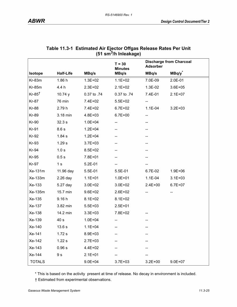
As a conservative design basis for the Offgas System, an average annual noble radiogas source term (based on 30-minute decay) of 3700 MBq/s of the 1971 mixture will be assumed. Table 11.3-1 provides the design basis noble gas source terms referenced to 30-minute decay. The system is mechanically capable of processing three times the source term without affecting delay time of the noble gases. Also listed is the isotopic distribution at t=0. With an air in-leakage of 51 sm3/h, this treatment system results in a delay of 46 hours for krypton and 42 days for xenon.
Using the given isotopic activities at the discharge of the Offgas System, the decontamination factor for each noble gas isotope can be determined. Subsection 11.1.1.1 presents source terms for normal operational and anticipated occurrence releases to the primary coolant. Tables in this section, if not designated otherwise, are based upon a design basis offgas release rate of 3700 MBq/s of noble gases and 25.9 MBq/s of I-131. For normal expected condition, the leak rates and doses are expected to be less than one quarter of the design basis numbers.
The average annual exposure at the site boundary during normal operation from all gaseous sources is not expected to exceed the dose objectives of 10CFR50 Appendix I in terms of actual
Gaseous Waste Management System 11.3-1
RS-5146900 Rev. 1
Design Control Document/Tier 2ABWR
doses to actual persons (Subsection 12.2.2.4). The radiation dose design basis for the treated offgas is to provide sufficient holdup until the required fraction of the radionuclides has decayed with the daughter products retained by the charcoal and the High Efficiency Particulate Air (HEPA) filter.
The Offgas System equipment is selected, arranged, and shielded to maintain occupational exposure as low as reasonably achievable in accordance with NRC Regulatory Guide 8.8.
The Offgas System is designed to the requirements of the General Design Criteria described in Subsection 11.2.1.2.
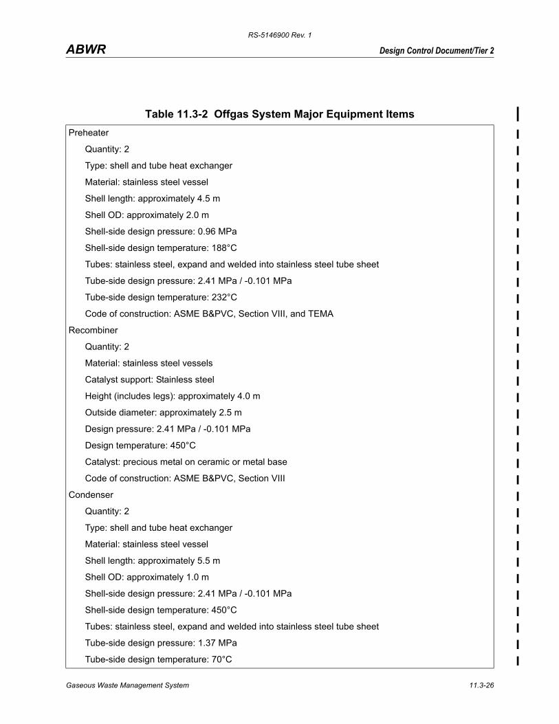
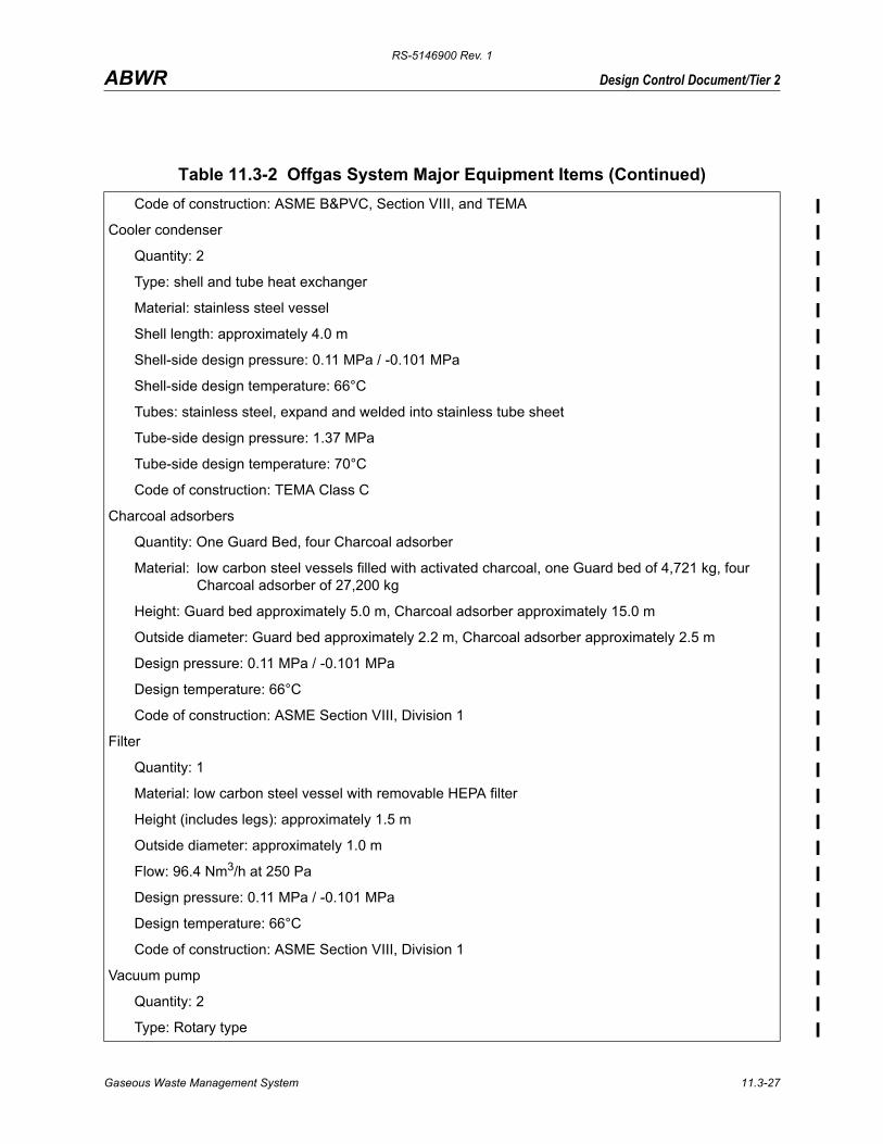
A list of the Offgas System major equipment items, including materials, rates, process conditions, number of units supplied, and relevant design codes is provided in Table 11.3-2.
The Offgas System is also designed to the following codes and standards:
(1) U.S. Nuclear Regulatory Commission, Code of Federal Regulations, 10CFR20, Standards for Protection Against Radiation; and 10CFR50 Appendix I, Numerical Guides for Design Objectives and Limiting Conditions for Operation to Meet the “As Low As Is Reasonably Achievable” for Radioactive Material in Light-Water Cooled Nuclear Power Reactor Effluents.
(2) Nuclear Regulatory Commission (NRC), Regulatory Guide 1.143, Design Guidance for Radioactive Waste Management Systems, Structures, and Components Installed in Light-Water-Cooled Nuclear Power Plants.
(3) American Society of Mechanical Engineers (ASME) Boiler and Pressure Vessel Code, Section VIII—Division 1.
(4) American Institute of Steel Construction (AISC), Manual of Steel Construction, 7th Edition.
(5) American National Standards Institute ANSI/ANS-55.4, Gaseous Radioactive Waste Processing Systems for Light Water Reactor Plants.
11.3.2.1 Offgas System Compliance With Part 20.1406
The Offgas System meets the requirements of 10 CFR 20.1406. The Offgas System design will minimize, to the extent practicable, contamination of the facility and the environment by removing the radioactive isotopes of noble gases and gaseous iodines drawn from the condenser and allowing them to decay to acceptable levels before the offgas stream discharges the decayed radionuclides to the environment via the plant stack. The Offgas System includes discharge monitoring that will automatically isolate the Offgas System from the environment in the unlikely event an unacceptable level of activity is detected in the Offgas System effluent. The Offgas System will be operated using approved plant procedures.
Gaseous Waste Management System 11.3-2
RS-5146900 Rev. 1
Design Control Document/Tier 2ABWR
The Offgas System is designed to minimize the generation of radioactive waste in that the charcoal in the carbon beds is not intended to be replaced during the entire plant life. To minimize carbon usage and to greatly reduce the potential for the Offgas System to spread contamination, the radiolysis-generated hydrogen and oxygen removed from the condenser by the Offgas System is recombined in a controlled manner in piping designed to withstand hydrogen and oxygen detonation. The resulting offgas is cooled and partially condensed to reduce the total influent mass and increase the relative radionuclide concentration that the carbon delay beds process. This increases the efficiency of the carbon delay beds and, therefore, reduces the mass of charcoal adsorbent. In addition, the cooler gas and resultant overall lower gas flow rate produces conditions for radionuclides to be more efficiently retained on the carbon in the delay beds. Additionally, a guard bed is positioned at the front end of the series of charcoal delay beds and is designed to bear the brunt of potential offgas operating events so that the follow on beds are minimally affected during the event
The initial loading of carbon is designed to adsorb the radionuclide gases present in the offgas stream without requiring periodic replacement. This design provides an objective that, during the operating life of the plant, carbon in the Offgas System delay beds should not contribute to or be processed into solid radwaste. The design objective can provide, at the end of the plant life, Offgas System decommissioning that primarily entails the removal of carbon adsorbent from the delay beds and processing it as dry solid radwaste.
11.3.3 Process Description
11.3.3.1 Process Functions
Major process functions of the Offgas System include the following:
(1) Dilution of air ejector offgas with steam to less than 4% hydrogen by volume
(2) Recombination of radiolytic hydrogen and oxygen into water to reduce the gas volume to be treated and the explosion potential in downstream process components
(3) Two-stage condensation of bulk water vapor first using Turbine Building Cooling Water (TWC) and then chilled water as the coolant reducing the gaseous waste stream temperature to 10°C or less
(4) Dynamic adsorption of krypton and xenon isotopes on charcoal at about 25°C
(5) Filtration of offgas
(6) Monitoring of offgas radioactivity levels and hydrogen gas concentration
(7) Release of processed offgas to the atmosphere
(8) Discharge of liquids to the main condenser and radwaste systems
Gaseous Waste Management System 11.3-3
RS-5146900 Rev. 1
Design Control Document/Tier 2ABWR
Major process functions of the ventilation systems are described in Section 9.4.
11.3.3.2 Process Equipment
Major process equipment of the Offgas System consists of the following:
(1) Process piping starting from the final steam dilution jets (SJAE) of the Main Condenser Evacuation System (not a part of the Offgas System)
(2) Recombiner trains which include a Preheater, a Recombiner, and a Condenser per train
(3) Cooler-condensers
(4) Activated charcoal adsorbers
(5) High efficiency particulate air (HEPA) filter
(6) Monitoring instrumentation
(7) Process instrumentation and controls
Major process equipment of the ventilation systems are described in Section 9.4.
11.3.3.3 Process Facility
The Offgas System process equipment is housed in a reinforced-concrete structure to provide adequate shielding. Charcoal adsorbers are installed in a temperature monitored and controlled vault. The facility is located in the Turbine Building to minimize piping.
Turbine Building Cooling Water (TCW) is used as the coolant for the offgas condensers. In this capacity:
(1) The temperature of coolant supplied to the offgas condenser should not exceed 56.6°C during periods of normal operation nor 43°C during periods of startup (main condenser evacuation) operation.
(2) The pressure of coolant supplied to the offgas condenser should not exceed the design pressure of the condenser.
(3) TCW isolation valves should be normally open to OG Condensers.
The gaseous waste stream is then cooled to 10°C or less in the cooler condenser. Chilled water (7°C) is used from the HNCW System (Subsection 9.2.12). The cooler condenser is located immediately above the offgas condenser and is designed to remove any condensed moisture from the gaseous waste stream. The condensed moisture drains into the offgas condenser where it is sent to the main condenser.
Gaseous Waste Management System 11.3-4
RS-5146900 Rev. 1
Design Control Document/Tier 2ABWR
The gaseous waste stream is heated to approximately 25°C by ambient heating in the charcoal vault.
Chapter 12 provides the radioactivity inventories of the major Offgas System components during normal plant operation. Radiation shielding design provides adequate protection of instrumentation and plant personnel required to monitor and operate the system.
11.3.4 Offgas System Description
11.3.4.1 Releases
The significant gaseous wastes discharged to the Offgas System during normal plant operation are radiolytic hydrogen and oxygen, main condenser air inleakage, and radioactive isotopes of krypton, xenon, nitrogen and oxygen. The radiation dose from gaseous discharge is primarily external rather than ingestion or inhalation. When releasing gases from the plant, the plume or cloud is the source of radiation to the ground. The maximum radiation corresponds to the zone of maximum ground concentration. This, in turn, is a function of wind velocity and direction, the presence of building obstructions in the wake and other meteorological conditions in the area. From the foregoing considerations, a maximum release rate from the plant stack or vent can be established such that the maximum radiation dose to any area in the environs is not exceeded.
Radioactive particles are present as a result of radioactive decay from the noble gas parents. These particulates are removed from the offgas stream by the condensation, adsorption, and filtration equipment. Therefore, effectively no radioactive particulates are released from the Offgas System to the plant stack or vent.
Radioiodines (notably I-131) may be present in significant quantities in the reactor steam and to some extent carried over through the condensation stages of the Offgas System. Removal of iodine takes place in the passage of process gas through the activated charcoal adsorbers, so that essentially no iodine is released from the Offgas System to the plant stack or vent.
The criterion for release of gaseous wastes to the atmosphere, excluding accident sequences, is that maximum external radiation dosage to the environment be maintained below the maximum dose objectives of Appendix I to 10CFR50 in terms of actual doses to actual offsite persons. An instantaneous release rate, established by 10CFR20, of several times the annual average permissible release rate limit may be permitted as long as the annual average is not exceeded. Every reasonable effort has been made to keep radiation exposures and release of radioactive materials as low as reasonably achievable (ALARA). The Offgas System discharge is routed to the plant stack.
11.3.4.2 Process Design
Primary design requirements and the process data for startup and normal operating conditions are shown on the process flow diagram (PFD) (Figure 11.3-1) and the piping and instrument
Gaseous Waste Management System 11.3-5
RS-5146900 Rev. 1
Design Control Document/Tier 2ABWR
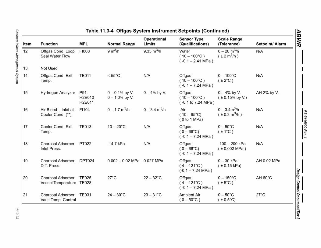
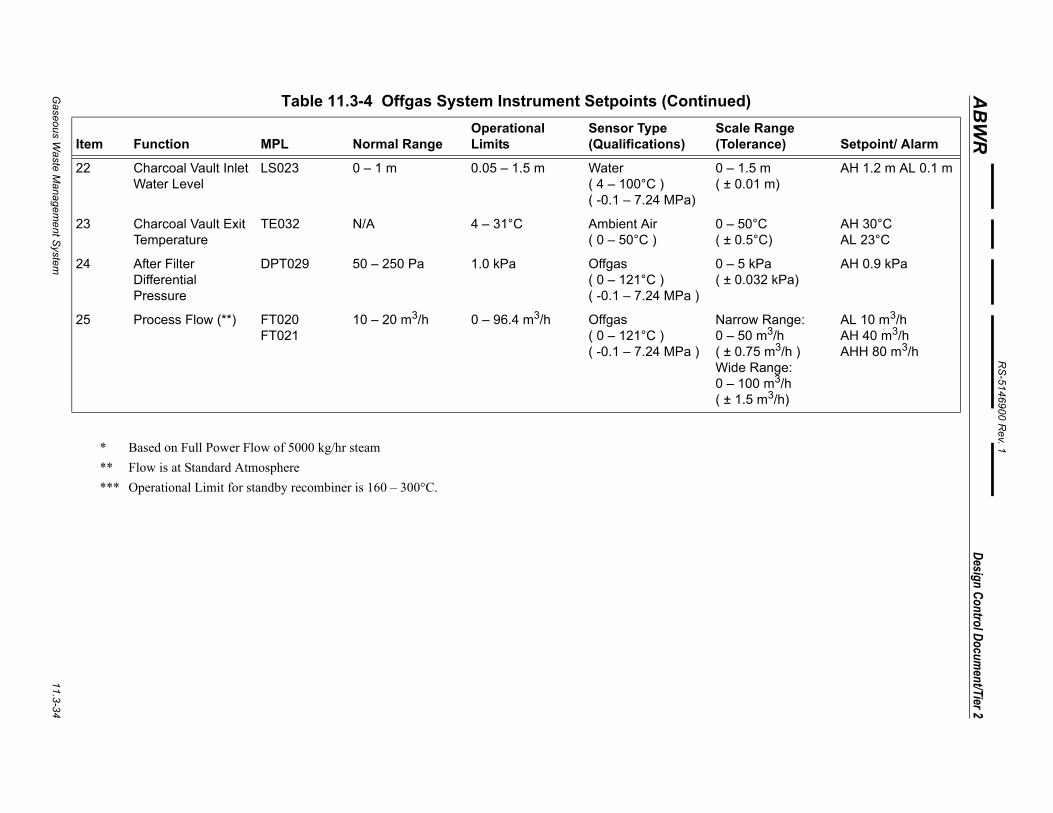
diagram (P&ID) (Figure 11.3-2). The Offgas System instrument setpoints are given in Table 11.3-4.
The SJAE suction valving is constrained to incorporate a minimum time period in bringing the recombiner units from zero to full offgas flow in order to limit transient stresses. The minimum time period is 60 seconds, equivalent to linear valve characteristics. The SJAE suction valving and steam supply valving is operable from the main control room.
11.3.4.2.1 Dilution Steam
The last stage SJAE is:
(1) Noncondensing
(2) Always supplied with sufficient steam to maintain the hydrogen concentration downstream at less than 4% by volume
(3) Located in close proximity to the previous condensing stage in order to minimize the length of line carrying a detonable mixture
(4) Provided a backpressure capability as shown on the Process Flow Diagram (PFD)
There is no Offgas System valve operation or failure mode which could cause the loss of dilution steam while the first-stage Steam Jet Air Ejectors (SJAE) are operating. The air ejectors are capable of maintaining required main condenser vacuum concurrent with maximum ejector backpressure. Steam flow to the last-stage ejector is constant during all operating modes of the Offgas System and is not modulated with reactor power level.
A flow meter is provided to measure the dilution steam flow to the last-stage air ejectors. If the dilution steam flow falls below a specified value, the process offgas line suction valve between the main condenser and SJAE closes automatically. The event is alarmed in the main control room. The valve will remain closed until proper steam flow has been established. A high dilution steam flow above a specified value also alarms in the main control room. This flow meter is shown on Figure 10.4.1.
The SJAE provides superheated steam at the inlet to the preheaters. The driving steam (dilution steam) to the SJAEs is nuclear steam or steam of nuclear quality. Nuclear quality steam is defined as steam having impurities in concentrations not exceeding that of nuclear steam.
Preheaters preheat gases to about 150°C for efficient catalytic recombiner operation and to ensure the absence of liquid water, which suppresses the activity of the recombiner catalyst. Maximum preheater temperature does not exceed 170°C should gas flow be reduced or stopped. This is accomplished by using a maximum steam pressure of 0.96 MPa, saturated. At startup, steam at this pressure is available before the process offgas is routed through the preheater to the recombiner catalyst. Electrical preheaters directly exposed to the offgas are not
Gaseous Waste Management System 11.3-6
RS-5146900 Rev. 1
Design Control Document/Tier 2ABWR
allowed. Each preheater connects to an independent final stage air ejector to permit separate steam heating of both recombiners during startup or drying one recombiner while the other is in operation. Preheater steam flow quantities are shown on the PFD. Preheater steam is nuclear quality steam for reliability. The preheater is sized to handle a dilution steam load of 115% of that shown on the PFD in addition to allowing for 5% plugged tubes.
11.3.4.2.2 Hydrogen/Oxygen Recombination
Minimum performance criteria for the catalytic recombiners are as follows:
(1) In normal full power operation, the hydrogen in the recombiner effluent does not exceed 0.1% by volume on a moisture-free basis, at the defined, 10 m3/h, minimum air flow.
(2) During startup or other reduced power operations (between 1 and 50% of reactor rated power), the hydrogen in the recombiner effluent does not exceed 1.0% by volume on a moisture free basis at the defined, 10 m3/h, minimum air flow.
(3) An intentional air bleed equal to minimum air flow is introduced into the system upstream of the operating recombiner when the main condenser air inleakage falls below the defined minimum air flow of 10 m3/h. The out-of-service recombiner catalyst is heated to at least 121°C by air (from the Instrument Air System) flowing through the hot standby offgas preheater before admitting process gas (containing hydrogen) to the recombiner. Three temperature sensing elements are provided in each catalyst bed and are located to record the temperature profile from inlet to outlet.
11.3.4.2.3 Condensing
The offgas condensers cool the recombiner effluent gas to a maximum temperature of 68°C for normal operation and 57°C for startup operation. The condenser includes baffles to reduce moisture entrainment in the offgas. The unit is sized to handle a dilution steam load of 115% of that shown on the PFD, in addition to allowing for 5% plugged tubes. The drain is capable of draining the collected condensate, including the 15% excess plus 9 m3/h, from the unit at both startup and normal operating conditions, taking into account the possibility of condensate flashing in the return line to the main condenser. The drain also incorporates a flow element so that higher flows due to tube leakage can be easily identified. The drain is a passive loop seal with a block valve operable from the main control room.
The gaseous waste stream is then cooled to 10°C or less in the cooler condenser. The cooler condenser is designed to remove any condensed moisture by draining it to the offgas condenser.
11.3.4.2.4 Adsorption
The activated charcoal uses “arbitrary” adsorption coefficient Karb values for krypton and xenon at 25°C of at least 60 and 1170 cm3/g, respectively (cm3 defined at 25°C, 1.0 atmosphere
Gaseous Waste Management System 11.3-7
RS-5146900 Rev. 1
Design Control Document/Tier 2ABWR
and 0% humidity). Separate Karb laboratory determinations of krypton and xenon are made for each manufacturer’s lot unless the manufacturer can supply proof convincing to the purchaser that other lots of the same production run immediately adjacent to the lot tested are equivalent to the lot tested with respect to krypton and xenon adsorption. Other adsorption tests (e.g., dynamic coefficients) may be acceptable, provided their equivalence to Karb tests for this purpose can be demonstrated. Charcoal particle size is 8-16 mesh (USS) with less than 0.5% under 20 mesh. Moisture content is less than 2% by weight. Ignition temperature will be above 150°C in air. Properties of activated charcoal used in the adsorber vessels are an optimization of the following:
(1) High adsorption for krypton and xenon
(2) High physical stability
(3) High surface area
(4) Low pressure drop
(5) Low moisture content
(6) High ignition temperature
(7) Dust-free structure
The krypton and xenon holdup time is closely approximated by the following equation:
(11.3-1)
where
T = Holdup time of a given gas
Kd = Dynamic adsorption coefficient for the given gas
M = Weight of charcoal
V = Flow rate of the carrier gas in consistent units
Dynamic adsorption coefficient values for xenon and krypton were reported by Browning (Reference 11.3-1). General Electric has performed pilot plant tests at the Vallecitos Nuclear Center and the results were reported at the 12th AEC Air Cleaning Conference (Reference 11.3-2).
TKdM
V------------=
Gaseous Waste Management System 11.3-8
RS-5146900 Rev. 1
Design Control Document/Tier 2ABWR
11.3.4.2.5 Filtration
The filter assembly contains a single high efficiency water-resistant filter element capable of removing at least 99.97% of 0.3 micrometer particles, as tested at the factory with mono-dispersed dioctylphthalate (DOP) smoke. The initial flow resistance of the filter does not exceed 2.54 cm water gauge (WG) at a water saturated air flow of 96.4 m3/h. An upstream demister pad is not required in the filter assembly. The filter is capable of operating under 100% relative humidity conditions.
11.3.4.2.6 Noble Gas Mixture
The fission product noble gas composition used as the nominal design basis is 3700 MBq/s(after 30-minute decay) as defined in Section 11.1. During normal operation with no fuel leaks, a release rate of noble gases of about 3.7 MBq/s (after 30-minute decay) may occur due to minute quantities of uranium contamination. The system is also capable of safe mechanical operation at release rates of up to 14800 MBq/s (after 30-minute decay). However, the limits of Subsection 11.3.4.1 are calculated based upon the design basis activity releases shown on the PFD.
11.3.4.2.7 Air Supply
Carrier gas is the air leakage from the main condenser after the radiolytic hydrogen and oxygen are removed by the recombiner. The air inleakage design basis is conservatively assumed to be 48.2 m3/h total. The Sixth Edition of Heat Exchange Institute Standards for Steam Surface condensers (Reference 11.3-3), Paragraph S1 (c) (2), indicates that with certain conditions of stable operation and suitable construction, noncondensibles (not including radiological decomposition products) should not exceed 10 m3/h for large condensers.
An air bleed supply is provided for:
(1) Dilution of residual hydrogen at air inleakages below 10 m3/h
(2) Valve stem sealing
(3) Recombiner startup
(4) Blocking during maintenance
(5) Instrument operation
(6) Providing an air flow through the standby recombiner when processing offgas
(7) Purging gas mixtures from process and instrument lines prior to maintenance
For dilution, at operating flows below 10 m3/h, the air bleed is 10 m3/h. Air flow rates for system purging are specified as normal flow on the PFD. The air is supplied from a compressor
Gaseous Waste Management System 11.3-9
RS-5146900 Rev. 1
Design Control Document/Tier 2ABWR
which does not use oil for lubrication of the compressor cylinder, as oil compromises the performance of the catalytic recombiners and charcoal adsorbers. All sources of air capable of entering the process downstream of the cooler condenser (i.e., valve double stem seals) have a dew point of less than –1°C. During both startup and normal operation, 1.7 m3/h of air is bled to the standby recombiner train downstream of the final SJAE for train purging after switchover. Flow indicators are provided on all air bleed lines to assure that proper air flow is being delivered to the process line or equipment. The air supply is protected from back flow of process gas by two check valves in series or a check valve and a pressure control valve in series.
11.3.4.2.8 Charcoal Vault Temperature
The charcoal adsorber vault air conditioning system is controlled at any selected temperature within a range of 23°C to 31°C. The temperature of the vault is maintained as indicated in Subsection 11.3.4.3.13.
11.3.4.2.9 Rangeability
The process can accommodate reactor operation from 0 to 100% of full power (full power is defined as the Normal Operating Case shown on the PFD). In normal operation, radiolytic gas production varies linearly with thermal power. The process can accommodate an air flow at 10 to 96.4 m3/h for the full range of reactor power operation.
Pressure drops through the entire system are as shown on the PFD.
11.3.4.2.10 Redundancy
All active equipment (e.g., valves and instrumentation) whose operation is necessary to maintain operability of the Offgas System is redundant. Passive equipment (e.g., charcoal adsorber) is not redundant. Instrumentation that performs an information function and is backed up by design considerations or other instrumentation need not be redundant. Instrumentation used to record hydrogen concentration or activity release (e.g., flow measurement, hydrogen analyzers) is also redundant.
Design provisions are incorporated which preclude the uncontrolled release of radioactivity to the environment as a result of any single equipment failure short of the equipment failure accident described in Chapter 15. An analysis of single equipment piece malfunctions is provided in Table 11.3-3.
Design precautions taken to prevent uncontrolled releases of activity include the following:
(1) The system design minimizes ignition sources so that a hydrogen detonation is highly unlikely even in the event of a recombiner failure.
Gaseous Waste Management System 11.3-10
RS-5146900 Rev. 1
Design Control Document/Tier 2ABWR
(2) The system pressure boundary is detonation-resistant in addition to the measures taken to avoid a possible detonation. Detonation resistance is achieved by specifying a design pressure for the process stream equipment which is approximately seventeen times the design operating pressure of the system.
(3) All discharge paths to the environment are monitored—the normal effluent path by the Process Radiation Monitoring System and the equipment areas by the Area Radiation Monitoring System.
(4) Dilution steam flow to the SJAE is monitored and alarmed, and the valving is required to be such that loss of dilution steam cannot occur without coincident loss of motive steam so that the process gas is sufficiently diluted if it is flowing at all.
11.3.4.2.11 Charcoal Adsorber Bypass
A piping and valving arrangement is provided which allows isolation and bypass of the charcoal adsorber vessel most likely to catch fire or become wetted with water, while continuing to process the offgas flow through the remaining adsorber vessels. This bypass valve arrangement is such that no single valve failure or valve mis-operation would allow total charcoal bypass. A nitrogen purge can be injected upstream of the vault entrance so that further combustion is prevented and the charcoal is cooled below its ignition temperature. Capability is provided to employ all or a portion of the charcoal adsorber vessels to treat the offgas flow during normal or off-standard process operating conditions.
Complete bypass of all charcoal adsorber vessels is also possible, where the main purpose of this bypass is to protect the charcoal during preoperational and startup testing when gas activity is zero or very low and when moisture is most likely to enter the charcoal beds. The bypass modes of charcoal operation is not normal for power operation. However, it may be used if the resulting activity release is acceptable.
11.3.4.2.12 Valves
All valves with operators located on the gas process stream are operable from the main control room. Where radiation levels permit, valves handling process fluids are installed in service areas where maintenance can be performed if needed during operation.
11.3.4.2.13 System Insulation
The Offgas System is adequately insulated, where needed, to insure that the criteria on the PFD are satisfied. Non-sweating type insulation is used to minimize moisture condensation on external side of piping. Insulation requirements are discussed in Subsection 11.3.4.3.8.
11.3.4.2.14 Nitrogen and Air Purge
A nitrogen purge and air supply line is connected to the offgas process just upstream of the first inline charcoal adsorber vessel (guard bed). This arrangement is to allow the vessel to be
Gaseous Waste Management System 11.3-11
RS-5146900 Rev. 1
Design Control Document/Tier 2ABWR
nitrogen purged after a possible fire is detected or dried with heated air if the charcoal is wetted, while the offgas flow is bypassed around it and through the remaining charcoal vessels. Another nitrogen purge line is also provided just upstream of the remaining charcoal adsorber vessels, which will allow them to be purged, if required, without interrupting the processing of offgas through the first inline charcoal vessel. The isolation valves in the nitrogen and air purge lines and the connection for the gas supply are accessible from outside the charcoal vault.
11.3.4.2.15 Identification of Combustion Hazard
All offgas equipment, piping and instrument lines that could contain a combustible mixture of offgas are color coded or marked in some other suitable manner to identify them. Tags are attached to the lines, and adjacent notices are provided to warn of the hazards of welding in these areas.
11.3.4.3 Mechanical Design
Portions of the system potentially contain a highly explosive mixture. Safety considerations require that ignition sources be minimized and that the system has the integrity to sustain an explosion.
Calculation methods for translation of detonation pressures into wall thickness are summarized in the ANSI-55.4 standard referenced in Subsection 11.3.2. Equipment and piping will be designed and constructed in accordance with the requirements of Table 11.2-1.
11.3.4.3.1 Materials
Per Regulatory Guide 1.143, regulatory position 1.1.2, materials for pressure-retaining components of process systems* are selected from those covered by the material specifications listed in Section II, Part A of the ASME Boiler and Pressure Vessel Code, except that malleable, wrought or cast-iron materials and plastic pipe are not allowed in this application. The components satisfy all of the mandatory requirements of the material specifications with regard to manufacture, examination, repair, testing, identification and certification.
Brittle fracture control required of carbon steels used for equipment in the Offgas System is as follows:
(1) For equipment, piping, and valves with operating temperatures 93°C or greater, there are no special requirements.
(2) For equipment, piping, and valves with operating temperatures in the range 0 to 93°C inclusive, there are no special requirements, except that high quality material is used (e.g., SA 106 pipe is used instead of A-53 material).
* “Process system” refers to that portion of the Offgas System that normally processes SJAE offgas.
Gaseous Waste Management System 11.3-12
RS-5146900 Rev. 1
Design Control Document/Tier 2ABWR
11.3.4.3.2 Pressure Relief
Adequate pressure relief is provided at all locations where it is possible to isolate a portion of the system containing a potential heat source. Adequate pressure relief is also provided downstream of pressure-reducing valves to protect equipment from overpressure.
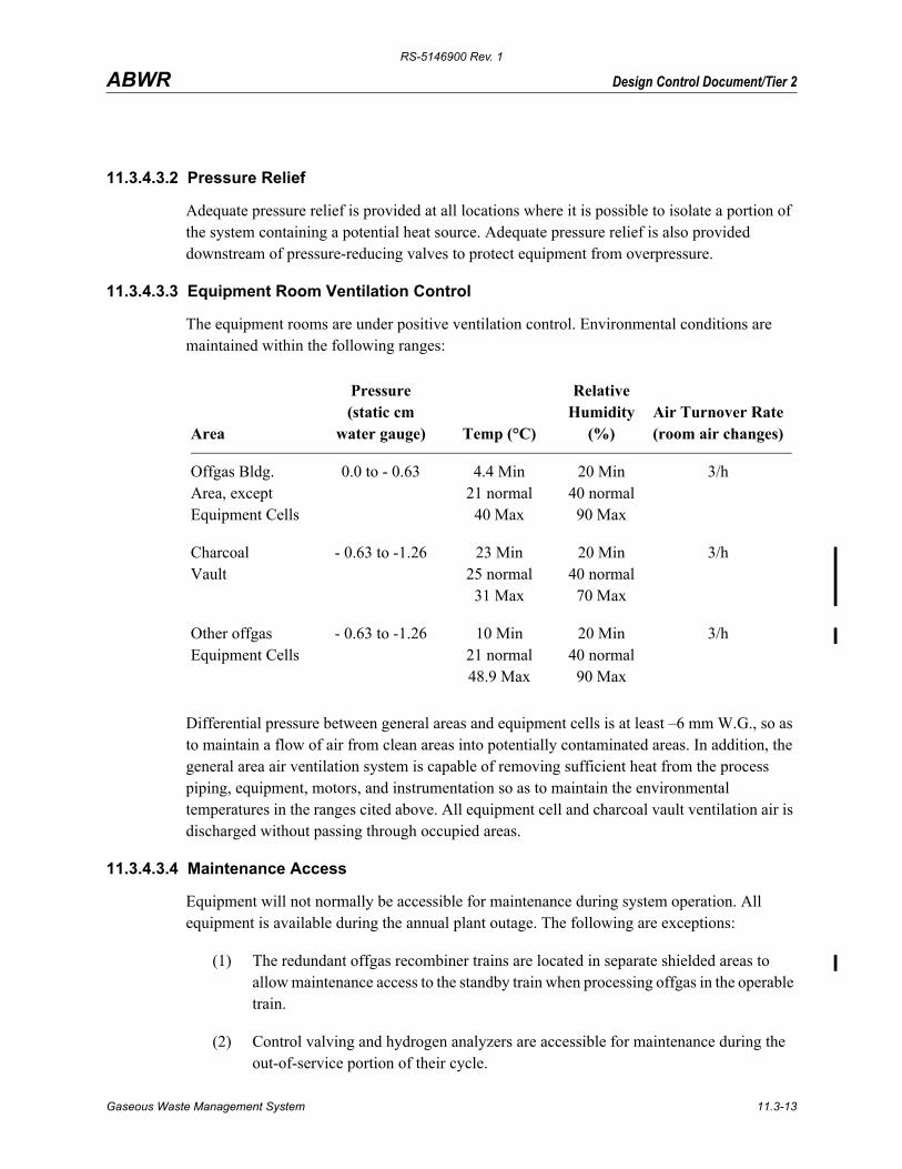
11.3.4.3.3 Equipment Room Ventilation Control
The equipment rooms are under positive ventilation control. Environmental conditions are maintained within the following ranges:
Differential pressure between general areas and equipment cells is at least –6 mm W.G., so as to maintain a flow of air from clean areas into potentially contaminated areas. In addition, the general area air ventilation system is capable of removing sufficient heat from the process piping, equipment, motors, and instrumentation so as to maintain the environmental temperatures in the ranges cited above. All equipment cell and charcoal vault ventilation air is discharged without passing through occupied areas.
11.3.4.3.4 Maintenance Access
Equipment will not normally be accessible for maintenance during system operation. All equipment is available during the annual plant outage. The following are exceptions:
(1) The redundant offgas recombiner trains are located in separate shielded areas to allow maintenance access to the standby train when processing offgas in the operable train.
(2) Control valving and hydrogen analyzers are accessible for maintenance during the out-of-service portion of their cycle.
Area
Pressure(static cm
water gauge) Temp (°C)
Relative Humidity
(%)Air Turnover Rate (room air changes)
Offgas Bldg.Area, exceptEquipment Cells
0.0 to - 0.63 4.4 Min21 normal
40 Max
20 Min40 normal90 Max
3/h
CharcoalVault
- 0.63 to -1.26 23 Min25 normal
31 Max
20 Min40 normal70 Max
3/h
Other offgasEquipment Cells
- 0.63 to -1.26 10 Min21 normal48.9 Max
20 Min40 normal90 Max
3/h
Gaseous Waste Management System 11.3-13
RS-5146900 Rev. 1
Design Control Document/Tier 2ABWR
(3) Charcoal vault air conditioning and ventilation equipment are accessible for maintenance during plant operation.
Maintenance valving and a 1.7 m3/h air bleed on the process side of each valve are provided for items (1) through (3) above. Each air line incorporates a flow indicator, isolation valve, and appropriate check valve(s).
The Offgas System is designed, constructed and tested to be as leaktight as practicable. The allowable leakage is a function of the system specific activity, the ventilation rate of the equipment cells, and the maximum permissible concentration (MPC) of the specific activity. Field testing of Offgas System leakage has demonstrated a practical limit of detectability of 1x10⁻⁶ cm3/s at standard atmosphere. The major offgas activities have an MPC of 0.185 Bq/cm3. This requires isotope identification, which for an offgas system consists of kryptons and xenons (10CFR20, Appendix B, Table 1, Column 1).
Design features which reduce or ease required maintenance or which reduce personnel exposure during maintenance include the following:
(1) Redundant components for all active, in-process equipment pieces located in shielded areas
(2) No rotating equipment in the radioactive process stream but located either where maintenance can be performed while the system is in operation or in non-radioactive streams
(3) Block valves with air bleed pressurization for maintenance which is required during plant operation
(4) Shielding of non-radioactive auxiliary subsystems from the radioactive process stream
Design features which reduce leakage and releases of radioactive material include the following:
(1) Extremely stringent leak rate requirements placed upon all equipment, piping and instruments and enforced by requiring as-installed helium leak tests of the entire process system
(2) Use of welded joints wherever practicable
(3) Specification of valve types with extremely low leak rate characteristics (i.e., bellows seal, double stem seal, or equal)
(4) Routing of drains through steam traps to the main condenser
Gaseous Waste Management System 11.3-14
RS-5146900 Rev. 1
Design Control Document/Tier 2ABWR
(5) Specification of stringent seat-leak characteristics for valves and lines discharging to the environment via other systems
11.3.4.3.5 Leakage
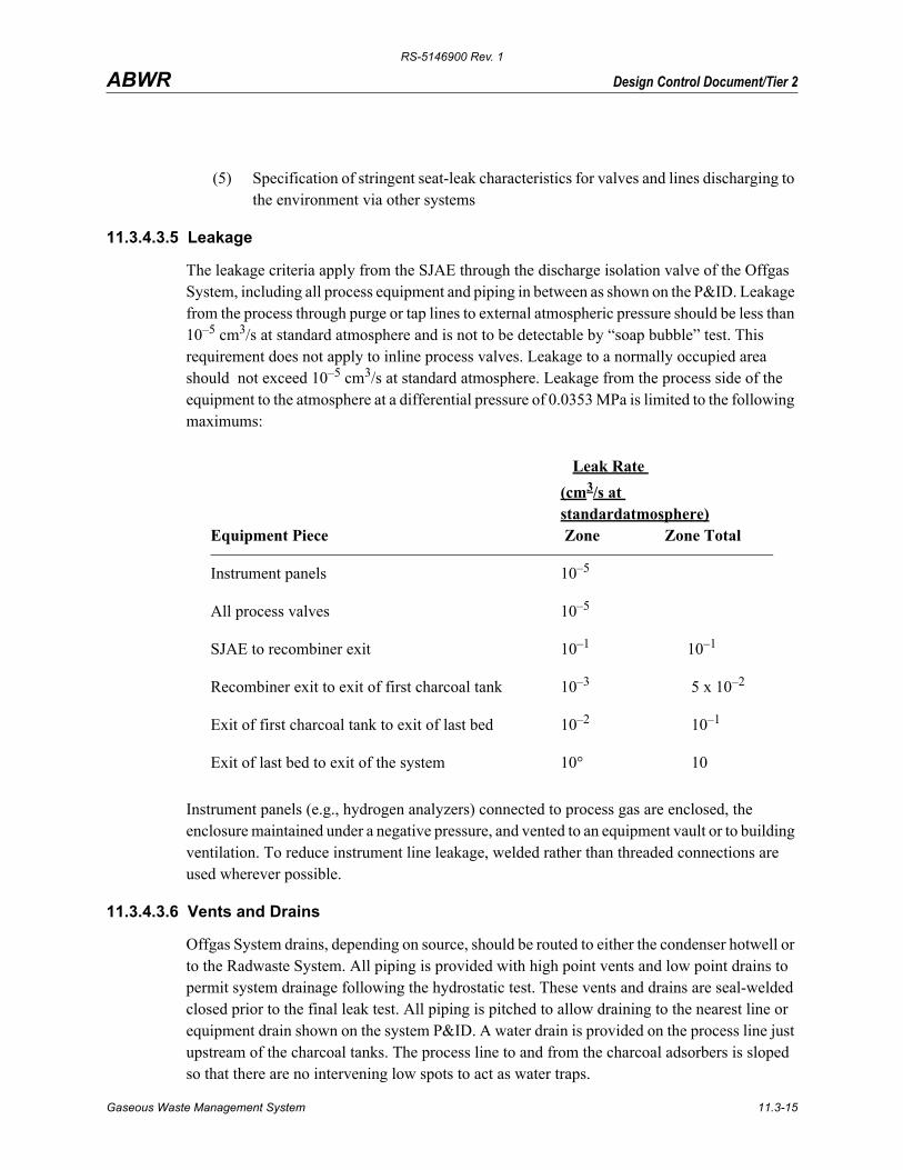
The leakage criteria apply from the SJAE through the discharge isolation valve of the Offgas System, including all process equipment and piping in between as shown on the P&ID. Leakage from the process through purge or tap lines to external atmospheric pressure should be less than 10–5 cm3/s at standard atmosphere and is not to be detectable by “soap bubble” test. This requirement does not apply to inline process valves. Leakage to a normally occupied area should not exceed 10–5 cm3/s at standard atmosphere. Leakage from the process side of the equipment to the atmosphere at a differential pressure of 0.0353 MPa is limited to the following maximums:
Instrument panels (e.g., hydrogen analyzers) connected to process gas are enclosed, the enclosure maintained under a negative pressure, and vented to an equipment vault or to building ventilation. To reduce instrument line leakage, welded rather than threaded connections are used wherever possible.
11.3.4.3.6 Vents and Drains
Offgas System drains, depending on source, should be routed to either the condenser hotwell or to the Radwaste System. All piping is provided with high point vents and low point drains to permit system drainage following the hydrostatic test. These vents and drains are seal-welded closed prior to the final leak test. All piping is pitched to allow draining to the nearest line or equipment drain shown on the system P&ID. A water drain is provided on the process line just upstream of the charcoal tanks. The process line to and from the charcoal adsorbers is sloped so that there are no intervening low spots to act as water traps.
Equipment Piece
Leak Rate (cm3/s at standardatmosphere) Zone Zone Total
Instrument panels 10–5
All process valves 10–5
SJAE to recombiner exit 10–1 10–1
Recombiner exit to exit of first charcoal tank 10–3 5 x 10⁻²
Exit of first charcoal tank to exit of last bed 10–2 10–1
Exit of last bed to exit of the system 10° 10
Gaseous Waste Management System 11.3-15
RS-5146900 Rev. 1
Design Control Document/Tier 2ABWR
11.3.4.3.7 Valves
No valves controlling the flow of process gas are located in the charcoal adsorber vault. Gate valves are rising-stem, wedge type. Valve operators may be chosen for operating pressure service (about 0.0343 MPa) rather than for the ASA rating required of the valve body for explosion resistance. For all valves exposed to process offgas, valve seats (trim) are all metal and spark resistant; that is, at least one surface should be fabricated from one of the following materials or equivalent: American Brass Co. Everdur, Beryllium Corp. of America-Berylco, or Allegheny Ludlum-Nitanol.
All valves exposed to process gas have bellows stem seals, double stem seals or equivalent. Bellows design pressure may be the system operating pressure, provided the bellows seal is backed up by a packing seal. Acceptable alternates to bellows seal design are as follows:
(1) A valve having a metal diaphragm backed up by a packing gland using Grafoil (Union Carbide Corp.) or equivalent packing.
(2) A valve having a double stem seal and lantern ring type bonnet, with Grafoil or equivalent packing with the lantern ring leakoff connection pressurized with nitrogen or air from an oil-free compressor to a pressure exceeding the normal system operating pressure. The pressurization line includes a flow indicating device mounted on the valve (such as a purge gas rotameter Schutte and Koerting Type 1875-V or equivalent) with a scale in the 0.5 to 1.0 cm3/s (at standard atmosphere) range, direct reading.
All valves exposed to process gas, except those specifically designated as control valves on the P&ID, incorporate a backseating feature to minimize potential leakage. The bonnet seal of all valves exposed to process gas are all metal or Grafoil type. It is recommended that the bonnets of valves in inhabited areas such as instrument panels be seal welded. All main process line valves are of bolted or welded bonnet design. Pressure seal bonnets are not used.
Valve external leakage is measured using an approved helium leak test procedure. In the case of double stem seal valves, the lantern ring may be pressurized during testing to the pressure it will see in service, and the valve shall exhibit neither external leakage in excess of the specified maximum nor inward leakage of pressurizing air in excess of 1.0 cm3/s at standard atmosphere.
11.3.4.3.8 Insulation Materials
Pipe insulating materials for offgas systems shall be from one of the following types or equivalent: S Glass, Refrasil, Cerafelt, Cerafiber, Marinite, Nextil, Fibrefax, Kaowool, or Nukon. Charcoal adsorber vault thermal insulation, if required, is resistant to vault radiation levels and is protected against moisture by a vapor barrier appropriate to the service. Chlorides are not permitted in the insulating material applied to stainless steel equipment.
Gaseous Waste Management System 11.3-16
RS-5146900 Rev. 1
Design Control Document/Tier 2ABWR
11.3.4.3.9 Gaskets
It is unacceptable to use gasket sorting techniques to pass the equipment leak test. The required gasket design must have a 95% probability of sealing each time the flanged joint is closed. Process piping and vessels use a metal or spiral wound gasket, incorporating a compression limiting ring.
11.3.4.3.10 Flange Surface Finish
Flanges used in the process stream have a maximum surface roughness of 3 µm rms in a circular lay.
11.3.4.3.11 Recombiners
The inlet piping has sufficient drains, traps and moisture separators to prevent liquid water from entering the recombiner vessel during startup. The recombiners are catalytic type with a non-dusting catalyst supported on metallic screens or ribbons. The catalyst is replaceable without requiring replacement of the external pressure vessel.
Fabrication procedures will take cognizance of catalyst poisons. Freons, oil, halogens, and welding fumes are to be excluded from the catalyst bed at all times.
Because the possibility exists for all types of catalysts to dust to some degree and then migrate to non-steam-diluted portions of the system downstream of the recombiner, no flow paths exist whereby unrecombined offgas can bypass the recombiners and ignite due to migrated catalyst.
11.3.4.3.12 Charcoal Adsorber Vessels
The charcoal adsorber beds are to be installed vertically. Bed settling could result in gas channeling. Bed settling in horizontal beds could result in excessive gas channeling.
Charcoal adsorber vessel packed heights, diameters, and flow arrangements are shown on the PFD and the P&ID. Channeling in the charcoal adsorbers is prevented by supplying an effective flow distributor on the inlet, which has long columns and a high bed-to-particle diameter ratio of approximately 500. Underhill (Reference 11.3-4) has stated that channeling or wall effects may reduce efficiency of the holdup bed if this ratio is not greater than 12. During transfer of the charcoal into the charcoal adsorber vessels, radial sizing of the charcoal will be minimized by pouring the charcoal (by gravity or pneumatically) over a cone or other instrument to spread the granules over the surface. Three temperature elements are installed within the first charcoal adsorber vessel to monitor the temperature profile with the flow path during operation. The remaining adsorber vessels each have a temperature element in the charcoal and one in the piping immediately downstream of the vessel.
Gaseous Waste Management System 11.3-17
RS-5146900 Rev. 1
Design Control Document/Tier 2ABWR
11.3.4.3.13 Charcoal Adsorber Vault
The temperature within the charcoal adsorber vault is maintained and controlled by appropriate connection(s) to the Turbine Building HVAC System. The flow rate and temperature of the air supplied to the vault has the capacity to cool the vault and equipment within from 66°C to 27°C in 48 hours. The decay heat is sufficiently small that, even in the no-flow condition, there is no significant loss of adsorbed noble gases due to temperature rise in the adsorbers. The HVAC design is capable of controlling the vault temperature within the range of 23 to 31°C.
The charcoal adsorber vault temperature is controlled in the range 23°C to 31°C. If it becomes necessary to heat a vessel or the vault to 66°C to facilitate drying the charcoal, portable heaters can be used. A smoke detector is installed in the exhaust ventilation duct from the charcoal adsorber vault to detect and provide alarm to the operator, as a charcoal fire within the vessel(s) usually results in the burning of the exterior painted surface.
11.3.4.3.14 Filter Cartridges
The offgas filter cartridge is designed to be readily removable from the filter vessel and replaceable.
11.3.4.3.15 Weld Inserts
Weld inserts, other than consumable ones, are prohibited from being in contact with the process or process discharges, unless they are ground out after the weld is completed.
11.3.4.3.16 Construction of Process Systems
Pressure-retaining components of process systems employ welded construction to the maximum practicable extent. Process piping systems include the first root valve on sample and instrument lines. Process lines are not less than 50A (2 inches), except around flow element. Sample and instrument lines are not considered as portions of the process systems. Flanged joints or suitable rapid disconnect fittings are not used except where maintenance requirements clearly indicate that such construction is preferable. Screwed connections in which threads provide the only seal are not used. Screwed connections backed up by seal welding or mechanical joints are used only on lines of 20A. In lines 20A or greater, but less than 65 A nominal pipe size, socket type welds are to be used. In lines 65A and larger, pipe welds are of the butt joint type.
All welding constituting the pressure boundary of pressure-retaining components will be performed by qualified welders employing qualified welding procedures.
11.3.4.3.17 Process-Piping Nozzles
The pipe-to-shell connections are fabricated with integral reinforcing. Nozzle reinforcing pads are not utilized and are not acceptable.
Gaseous Waste Management System 11.3-18
RS-5146900 Rev. 1
Design Control Document/Tier 2ABWR
11.3.4.3.18 Traps
All traps incorporate a strainer upstream, in a reasonably accessible location for maintenance, to minimize the chance of debris plugging the trap. Trap designs are not used which, like the inverted-bucket design, incorporate a small, easily plugged orifice. The strainer blowdown line and trap bypass line used for trap maintenance is routed back to the main drain line downstream of the trap to minimize the possibility of escaping process gas.
11.3.4.3.19 Moisture Separator
A moisture separator should be incorporated into the cooler-condenser heat exchanger.
11.3.5 Other Radioactive Gas Sources
Radioactive gases are present in the power plant buildings as a result of process leakage and steam discharges. The process leakage is the source of the radioactive gases in the air discharged through the ventilation system. The design of the ventilation system is described in Section 9.4, the radiation activity levels from the ventilation systems in Section 12.3, and the ventilation flow rates in Section 9.4.
Main condenser mechanical vacuum pump operation, as part of the main condenser evacuation system, is described in Section 10.4.
11.3.6 Instrumentation and Control
Control and monitoring of the offgas process equipment is performed both locally and remotely from the main control room, as shown on the P&ID. Indication, recording and alarm functions are shown on the P&ID. Generally, system control is from the main control room. Instrument components are installed, wherever possible, in accessible areas to facilitate operation and maintenance. Only instrument sensing elements are permitted behind shield walls.
The temperature of the gaseous waste stream is measured in the preheater and at various locations in the recombiner to assure that recombination is occurring. The gaseous waste stream temperature is also measured after both the offgas condenser and the cooler condenser to assure the stream is cooled sufficiently to remove undesired moisture. All of these temperatures are alarmed in the main control room.
The flow rate of the air ejector offgases downstream of the recombiner is continuously recorded. This flow rate, in conjunction with activity concentrations in Bq/cc, as measured by the monitor downstream of the recombiners and the monitor downstream of the charcoal adsorbers, will permit monitoring fission gases from the reactor, calculation of offgas discharge to the vent in MBq and will permit calculation of the charcoal adsorber system performance. Activity release that would exceed the maximum permitted instantaneous value is alarmed, and causes closure of the final process gas release valve.
Instrumentation and control of the ventilation systems are described in Section 9.4.
Gaseous Waste Management System 11.3-19
RS-5146900 Rev. 1
Design Control Document/Tier 2ABWR
11.3.7 Quality Control
The following, exerpted from ANS-55.4 (Section 11.3.2), provides quality control features to be established for the design, construction, and testing of the Offgas System.
System Designer and Procurer
(1) Design and Procurement Document Control: Design and procurement documents shall be independently verified for conformance to the requirements of this standard by individual(s) within the design organization who are not the originators of the document. Changes to these documents shall be verified or controlled to maintain conformance to this standard.
(2) Control of Purchased Material, Equipment and Services: Measures shall be established to ensure that suppliers of material, equipment and construction services are capable of supplying these items to the quality specified in the procurement documents. This may be done by an evaluation or a survey of the suppliers’ products and facilities.
(3) Handling, Storage and Shipping: Instructions shall be provided in procurement documents to control the handling, storage, shipping and preservation of material and equipment to prevent damage, deterioration and reduction of cleanness.
System Constructor
(1) Inspection: In addition to required code inspections, a program for inspection of activities affecting quality shall be established and executed by, or for, the organization performing the activity to verify conformance with the documented instructions, procedures, and drawings for accomplishing the activity. This shall include the visual inspection of components prior to installation for conformance with procurement documents and the visual inspection of items and systems following installation, cleaning and passivation (where applied).
(2) Inspection, Test and Operating Status: Measures shall be established to provide for the identification of items which have satisfactorily passed required inspections and tests.
(3) Identification and Corrective Action for Items of Nonconformance: Measures shall be established to identify items of nonconformance with regard to the requirements of the procurement documents or applicable codes and standards and to identify the action taken to correct such items.
Quality control for the ventilation systems is described in Section 9.4.
Gaseous Waste Management System 11.3-20
RS-5146900 Rev. 1
Design Control Document/Tier 2ABWR
11.3.8 Seismic Design
Offgas System equipment and piping are classified non-Seismic Category I. The support elements of the charcoal adsorbers, including legs or skirts, lateral supports (if required) and anchor bolting, are designed such that the fundamental frequency of the vessels including all support elements, is greater than 33 Hz. The charcoal adsorbers, including support elements, are designed to static seismic coefficients of 0.2g horizontal and 0.0g vertical. Stress levels in the charcoal adsorber support elements do not exceed 1.33 times the allowable stress levels permitted by the AISC Manual of Steel Construction, 7th Edition (Section 11.3.2).
Seismic design for the ventilation systems is described in Section 9.4.
11.3.9 Testing
Shop fabricated equipment and the piping system will pass the required tests for integrity as specified in the pressure integrity design specification. In all cases, pressure-containing butt welds exposed to radioactive gas will have 100% radiography and all other pressure-containing welds will have liquid penetrant or magnetic particle surface inspection.
Completed process systems are pressure tested to the maximum practicable extent. Piping systems are hydrostatically tested in their entirety, utilizing available valves or temporary plugs at atmospheric tank connections. Hydrostatic testing of piping systems is performed at a pressure equal to 1.5 times the design pressure. However, if 1.5 times the pressure becomes less than 0.52 MPaG, it is performed at 0.52 MPaG. Hydrostatic testing will not be performed with the recombiner catalyst, the activated carbon or the filter element in place in the system. Pneumatic testing may be substituted for hydrostatic testing in accordance with the applicable Code of Construction. However, any pressure testing performed after the activated carbon is in place in the vessels would utilize vaporized liquid nitrogen (not compressed air) to avoid contamination or combustion of the carbon.
The installed Offgas System will be leak tested to verify that the leak criteria of Subsection 11.3.4.3.5 are met. A helium leak test is used. Testing is completed prior to application of thermal insulation or corrosion protective coating. Surfaces of the Offgas System to be leak tested will be clean and free of water, oil, grease, paint and other contaminants which would interfere with the leak test.
The object of the preoperation tests is to test installed equipment and piping configurations. Preoperation tests are intended to verify that the equipment was built and installed correctly. The preoperation tests are not complete design tests nor full range calibrations.
The coolant input temperature and flow rate for the offgas condenser and cooler-condenser will be verified to be in compliance with the design basis given on the PFD. The offgas filter cartridge is tested for proper sealing and filtration.
Gaseous Waste Management System 11.3-21
RS-5146900 Rev. 1
Design Control Document/Tier 2ABWR
The hydrogen analyzers are tested for proper functioning. During operation, the analyzer will be calibrated on the manufacturer’s recommended interval as a minimum.
The equipment operation will be verified at about 10 and 100% of the normal flow case of the PFD.
During reactor startup, after air ejector cut-in and Offgas System startup, the following will be verified:
(1) Air ejector function, through offgas pressure and flow
(2) Preheater operation, through recombiner inlet temperature
(3) Catalyst temperature and H2 effluent concentration
(4) Offgas condenser operation
The pressure drops of the Offgas System will be verified for both startup and normal operation.
In-place testing facilities are provided for testing the integrity of the filter and filter seal after installation. Such facilities include a polydisperse dioctylphthalate (DOP) smoke generator, means for smoke injection and dispersion upstream of the filter, and analytical instrumentation for determining DOP smoke concentration upstream and downstream of the filter.
Means should be provided for testing the leaktightness of the installed filter when filters are initially installed or when they are replaced. Tests should include the following:
(1) New filters should be factory tested for efficiency.
(2) Immediately prior to installation, new filters should be visually inspected for damage using strong backlighting.
(3) After installation and prior to use, the filter should be DOP tested to ensure that it is sealed and that no unseen filter damage exists.
The test at the time of filter installation or replacement uses DOP (dioctylphthalate) aerosol to determine whether the installed filter meets the minimum in-place efficiency of 99.97% retention. The DOP test consists of injecting cold (polydisperse) DOP in a 16.5 to 33 cubic meters per hour air stream so that it is well mixed when it reaches the filter. The DOP and air enter the offgas pipe at least eight offgas pipe diameters upstream of the filter and inlet sampling point. The outlet sampling point is located at least eight pipe diameters downstream of the outlet of the filter, and the return line from the DOP sampler must be located at least four pipe diameters beyond the outlet sampling point. Sampling connection from the inlet and outlet sampling line should be made through a DOP measuring instrument to a vacuum pump of 1.3 to 2 cubic meters per hour capacity. The DOP measuring instrument is used to measure
Gaseous Waste Management System 11.3-22
RS-5146900 Rev. 1
Design Control Document/Tier 2ABWR
individual DOP concentrations at the filter inlet and outlet, thereby measuring filter efficiency by comparing these concentrations. At the end of the test, the process lines are purged with bleed air.
The DOP from filter testing is not allowed into the activated carbon.
Performance tests during plant operation should consist only of taking filter inlet and outlet samples by drawing them through Millipore filters for laboratory measurement of radioactive particles collected.
Filter test equipment used with the Offgas System should have the following characteristics:
(1) The smoke injection and sample piping should have the same pressure rating as the offgas line through the first valve.
(2) The smoke generator and measuring instrumentation, including the vacuum pump, can be made portable for common use on the Standby Gas Treatment System.
(3) The DOP connections should be installed so that representative inlet and outlet samples can be obtained.
Testing requirements for the ventilation systems are listed in Section 9.4.
11.3.10 Radioactive Releases
11.3.10.1 Release Points
The primary release point for the ABWR plant is the Reactor Building plant stack. This stack serves as the release point for the Reactor Building, Turbine Building, and Radwaste Building. Other exhaust points for clean releases are the roof top vents for the Control and Service Buildings and the Service Building health physics room roof vent. The Reactor Building stack is a roof-mounted steel shell in a steel framework extending to a height of 76m above ground level. The closest plant buildings are the Reactor Building to a height of 37.7m and the Turbine Building to a height of 43m. A sketch of the layout for the plant is shown in Figure 1.2-1 and a sketch of the stack with perspective to the local buildings is shown in Figure 15.6-4.
11.3.10.2 Ventilation Releases
Ventilation releases are given in Section 12.2 and assume releases from the plant stack with a total flow rate of at least 566,000 m3/h through a 2.4m diameter circular stack at 76m above ground level. Ventilation releases are assumed to be less than 40°C. The ABWR is licensed for a generic site for which no specific site parameters have been stipulated by the NRC; therefore, an ambient temperature of 38°C is assumed based upon Table 2.0-1.
Gaseous Waste Management System 11.3-23
RS-5146900 Rev. 1
Design Control Document/Tier 2ABWR
11.3.10.3 Dilution Factors
Since the ABWR certification stipulates a generic site and in lieu of NRC guidance on meteorological parameters for generic sites, recourse was made to the determination of the annual average dilution factors (χ/Q and D/Q) for multiple sites. Using data described in Reference 11.3-5 for 26 sites around the U.S. including New York City (derived from Reference 11.3-6) and the above parameters, a determination of χ/Q and D/Q variability using code XOQDOQ (Reference 11.3-7) was made. From this, a minimum χ/Q of 2.0 x 10⁻⁶ and a minimum D/Q of 4 x 10⁻⁸ was used.
11.3.10.4 Estimated Doses
The calculated exposures are discussed in Section 12.2.
11.3.11 COL License Information
11.3.11.1 Compliance with Appendix I to 10CFR50
The COL applicant shall demonstrate compliance with Appendix I to 10CFR50 numerical guidelines for offsite radiation doses as a result of gaseous or airborne radioactive effluents during normal plant operations, including anticipated operational occurrences shall be provided.
11.3.12 References
11.3-1 Browning, W.E., et al., “Removal of Fission Product Gases from Reactor Offgas Streams by Adsorption”, June 11, 1959 (ORNL) CF59-6-47.
11.3-2 Seigwarth, D.P., “Measurement of Dynamic Adsorption Coefficients for Noble Gases on Activated Carbon”, 12th AEC Air Cleaning Conference.
11.3-3 Standards for Steam Surface Condensers, Sixth Edition, Heat Exchange Institute, New York, NY (1970).
11.3-4 Underhill, Dwight, et al., “Design of Fission Gas Holdup Systems”, Proceedings of the Eleventh AEC Air Cleaning Conference, 1970, p. 217.
11.3-5 Hall, Irving, et al, “Generations of Typical Meteorological Years for 26 SOLMET Stations”, Sandia National Laboratory, SAND78-1601.
11.3-6 Ritchie, Lynn T, et al, “Calculations of Reactor Accident Consequences Version 2 CRAC2: Computer Code”, NUREG/CR-2326, February 1983.
11.3-7 Sagendorf, J.F., et al, “XOQDOQ: Computer Program for the Meteorolgical Evaluation of Routine Effluent Releases at Nuclear Power Stations”, NUREG/CR-2919, September 1982.
Gaseous Waste Management System 11.3-24
RS-5146900 Rev. 1
Design Control Document/Tier 2ABWR
Table 11.3-1 Estimated Air Ejector Offgas Release Rates Per Unit(51 sm3/h Inleakage)
T = 30MinutesMBq/s
Discharge from Charcoal Adsorber
Isotope Half-Life MBq/s MBq/s MBq/y*
* This is based on the activity present at time of release. No decay in environment is included.
Kr-83m 1.86 h 1.3E+02 1.1E+02 7.0E-09 2.0E-01
Kr-85m 4.4 h 2.3E+02 2.1E+02 1.3E-02 3.6E+05
Kr-85†
† Estimated from experimental observations.
10.74 y 0.37 to .74 0.37 to .74 7.4E-01 2.1E+07
Kr-87 76 min 7.4E+02 5.5E+02 --
Kr-88 2.79 h 7.4E+02 6.7E+02 1.1E-04 3.2E+03
Kr-89 3.18 min 4.8E+03 6.7E+00 --
Kr-90 32.3 s 1.0E+04 -- --
Kr-91 8.6 s 1.2E+04 -- --
Kr-92 1.84 s 1.2E+04 -- --
Kr-93 1.29 s 3.7E+03 -- --
Kr-94 1.0 s 8.5E+02 -- --
Kr-95 0.5 s 7.8E+01 -- --
Kr-97 1 s 5.2E-01 -- --
Xe-131m 11.96 day 5.5E-01 5.5E-01 6.7E-02 1.9E+06
Xe-133m 2.26 day 1.1E+01 1.0E+01 1.1E-04 3.1E+03
Xe-133 5.27 day 3.0E+02 3.0E+02 2.4E+00 6.7E+07
Xe-135m 15.7 min 9.6E+02 2.6E+02 -- --
Xe-135 9.16 h 8.1E+02 8.1E+02
Xe-137 3.82 min 5.5E+03 2.5E+01
Xe-138 14.2 min 3.3E+03 7.8E+02 --
Xe-139 40 s 1.0E+04 -- --
Xe-140 13.6 s 1.1E+04 -- --
Xe-141 1.72 s 8.9E+03 -- --
Xe-142 1.22 s 2.7E+03 -- --
Xe-143 0.96 s 4.4E+02 -- --
Xe-144 9 s 2.1E+01 -- --
TOTALS 9.0E+04 3.7E+03 3.2E+00 9.0E+07
Gaseous Waste Management System 11.3-25
RS-5146900 Rev. 1
Design Control Document/Tier 2ABWR
Table 11.3-2 Offgas System Major Equipment ItemsPreheater
Quantity: 2
Type: shell and tube heat exchanger
Material: stainless steel vessel
Shell length: approximately 4.5 m
Shell OD: approximately 2.0 m
Shell-side design pressure: 0.96 MPa
Shell-side design temperature: 188°C
Tubes: stainless steel, expand and welded into stainless steel tube sheet
Tube-side design pressure: 2.41 MPa / -0.101 MPa
Tube-side design temperature: 232°C
Code of construction: ASME B&PVC, Section VIII, and TEMA
Recombiner
Quantity: 2
Material: stainless steel vessels
Catalyst support: Stainless steel
Height (includes legs): approximately 4.0 m
Outside diameter: approximately 2.5 m
Design pressure: 2.41 MPa / -0.101 MPa
Design temperature: 450°C
Catalyst: precious metal on ceramic or metal base
Code of construction: ASME B&PVC, Section VIII
Condenser
Quantity: 2
Type: shell and tube heat exchanger
Material: stainless steel vessel
Shell length: approximately 5.5 m
Shell OD: approximately 1.0 m
Shell-side design pressure: 2.41 MPa / -0.101 MPa
Shell-side design temperature: 450°C
Tubes: stainless steel, expand and welded into stainless steel tube sheet
Tube-side design pressure: 1.37 MPa
Tube-side design temperature: 70°C
Gaseous Waste Management System 11.3-26
RS-5146900 Rev. 1
Design Control Document/Tier 2ABWR
Code of construction: ASME B&PVC, Section VIII, and TEMA
Cooler condenser
Quantity: 2
Type: shell and tube heat exchanger
Material: stainless steel vessel
Shell length: approximately 4.0 m
Shell-side design pressure: 0.11 MPa / -0.101 MPa
Shell-side design temperature: 66°C
Tubes: stainless steel, expand and welded into stainless tube sheet
Tube-side design pressure: 1.37 MPa
Tube-side design temperature: 70°C
Code of construction: TEMA Class C
Charcoal adsorbers
Quantity: One Guard Bed, four Charcoal adsorber
Material: low carbon steel vessels filled with activated charcoal, one Guard bed of 4,721 kg, four Charcoal adsorber of 27,200 kg
Height: Guard bed approximately 5.0 m, Charcoal adsorber approximately 15.0 m
Outside diameter: Guard bed approximately 2.2 m, Charcoal adsorber approximately 2.5 m
Design pressure: 0.11 MPa / -0.101 MPa
Design temperature: 66°C
Code of construction: ASME Section VIII, Division 1
Filter
Quantity: 1
Material: low carbon steel vessel with removable HEPA filter
Height (includes legs): approximately 1.5 m
Outside diameter: approximately 1.0 m
Flow: 96.4 Nm3/h at 250 Pa
Design pressure: 0.11 MPa / -0.101 MPa
Design temperature: 66°C
Code of construction: ASME Section VIII, Division 1
Vacuum pump
Quantity: 2
Type: Rotary type
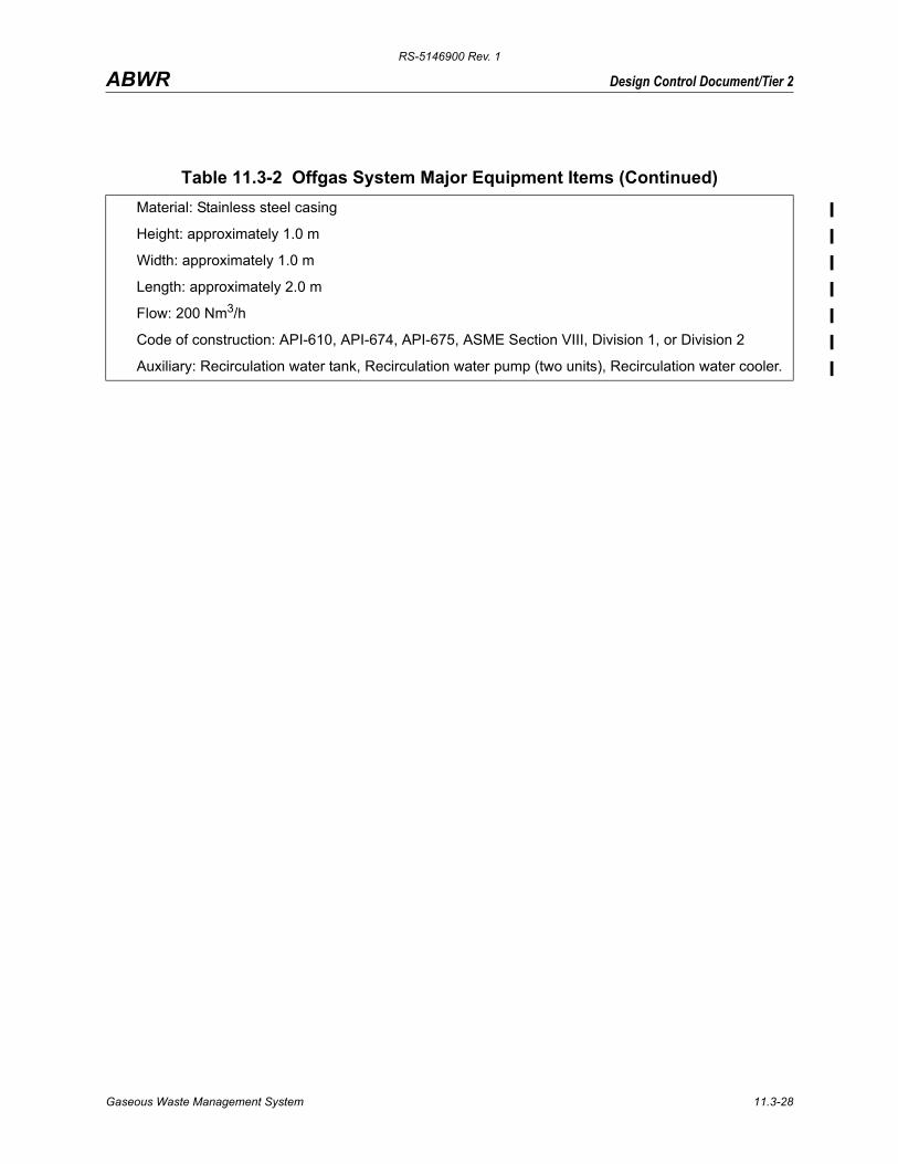
Table 11.3-2 Offgas System Major Equipment Items (Continued)
Gaseous Waste Management System 11.3-27
RS-5146900 Rev. 1
Design Control Document/Tier 2ABWR
Material: Stainless steel casing
Height: approximately 1.0 m
Width: approximately 1.0 m
Length: approximately 2.0 m
Flow: 200 Nm3/h
Code of construction: API-610, API-674, API-675, ASME Section VIII, Division 1, or Division 2
Auxiliary: Recirculation water tank, Recirculation water pump (two units), Recirculation water cooler.
Table 11.3-2 Offgas System Major Equipment Items (Continued)
When the hydrogen and oxygen concentrations exceed 4 and 5 volume percent, respectively, the process gas becomes flammable.
Automatic system isolation on low steam flow.
Inadequate steam flow will cause overheating and deterioration of the catalyst.
Steam flow to be held at constant maximum flow regardless of plant power level.
Wear of steam supply nozzle of ejector
Increased steam flow to recombiner could reduce degree of recombination at low power levels. High discharge temperature from the recombiner condenser could result due to inadequate condenser capacity.
Low-temperature alarms on preheater exit (catalyst inlet). Downstream H2 analyzer. High-temperature alarm on exit from recombiner.
Preheater Steam leak Would further dilute offgas. Steam consumption would increase.
Spare recombiner.
Low-pressure steam supply
Recombiner performance would fall off at low-power level, and hydrogen content of recombiner gas discharge would increase eventually to a combustible mixture.
Low-temperature alarms on preheater exit (catalyst inlet). Downstream H2 analyzer.
Recombiner Catalyst gradually deactivates
Temperature profile changes through catalyst. Eventually, excess H2 would be detected by H2 analyzer or by gas flow meter. Eventually, the gas could become combustible.
Temperature probes in catalyst bed and H2 analyzer provided. Spare recombiner.
Catalyst gets wet at start
H2 recombination fails. Eventually, the gas could become combustible.
Condensate drains, temperature probes in recombiner. Air bleed system at startup. Spare recombiner. Hydrogen analyzer.
Condenser Cooling water leak
The coolant (TCW) would leak to the process gas (shell) side. This would be detected if drain well liquid level increases. Moderate leakage would be of no concern from a process standpoint. (The process condensate drains to the hotwell.)
Drain well high level alarm. Redundant recombiner.
Liquid level Instruments fail
If drain valve fails to open, water will build up in the condenser and pressure drop will increase.
High- and low-level alarms on drain well level. Redundant recombiner.
Gaseous Waste Management System 11.3-29
RS-5146900 Rev. 1
Design Control Document/Tier 2ABWR
The high ΔP, if not detected by instrumentation, could cause pressure buildup in the main condenser and eventually initiate a reactor scram.
If a drain valve fails to close, gas will recycle to the main condenser, increase the load on the SJAE, and cause a slight backpressure on the main condenser.
Cooler condenser
Corrosion of tubes
Water would leak into process (shell) side and be discharged to clean radwaste.
Stainless-steel tubes specified.
Moisture separator in cooler condenser
Corrosion of wire mesh element
Increased moisture would be retained in process gas routed to gas dryers. Over a long period, the desiccant dryer cycle period would deteriorate as a result of moisture pickup.
Stainless steel mesh specified. Spare cooler condenser provided. Moisture detector provided downstream of gas dryer.
Charcoal adsorbers
Charcoal gets wet
Charcoal performance will deteriorate gradually as moisture deposits. Holdup times for krypton and xenon would decrease, and plant emissions would increase. Provisions made for drying charcoal as required during annual outage.
High instrumented, mechanically simple gas dehumidification system.
After filter Hole in filter media
Probable of no real consequence. The charcoal itself will retain virtually all solid daughters. Particulates released would be the negligible amount formed in the pipe run after the exit of the last charcoal adsorber.
ΔP instrumentation provided.
System Internal detonation
Release of radioactivity if pressure boundary fails.
Main process equipment and piping are designed to contain a detonation.
Internal damage to the recombiner and its heat exchanger.
Redundant recombiner, damaged internals can be repaired.