Figure 1: Lift A Figure 2: Effect of increasing angle B HVLS Technology and Terminology HVLS fans are a great way to economically reduce heating and cooling bills, as well as ensure occupant comfort. As HVLS fans are concerned with large scale air movement and operate differently than most HVAC fans, much of the industry terminology can be somewhat foreign to users. This document is intended to help increase familiarity with the specialized terminology associated with HVLS fans. Lift: As an airfoil (fan blade) moves through air, the lower surface of the blade encounters higher pressure than the top surface. Through this pressure gradient, lift is generated. As HVLS fans are fixed to the ceiling, lift is more commonly referred to as “downward air movement”. Angle of Attack: Angle of attack refers to the angle at which a fan blade moves through the air, relative to horizontal. Larger angles of attack correlate to greater downward air movement, up to the point where the angle of attack is equal to the stall angle. Stall Angle: When the angle of attack of an airfoil surpasses the airfoil’s stall angle, the air flowing over the airfoil no longer flows along the surface of the fan blade, becoming turbulent. This leads to vibration and less downward air movement. HVLS fan blades are typically fixed at an incline equal to the stall angle, maximizing the downward air movement generated by each blade. Rupp HVLS fans with tubercle technology offer the industry’s largest stall angle of 22 degrees.
Transcript
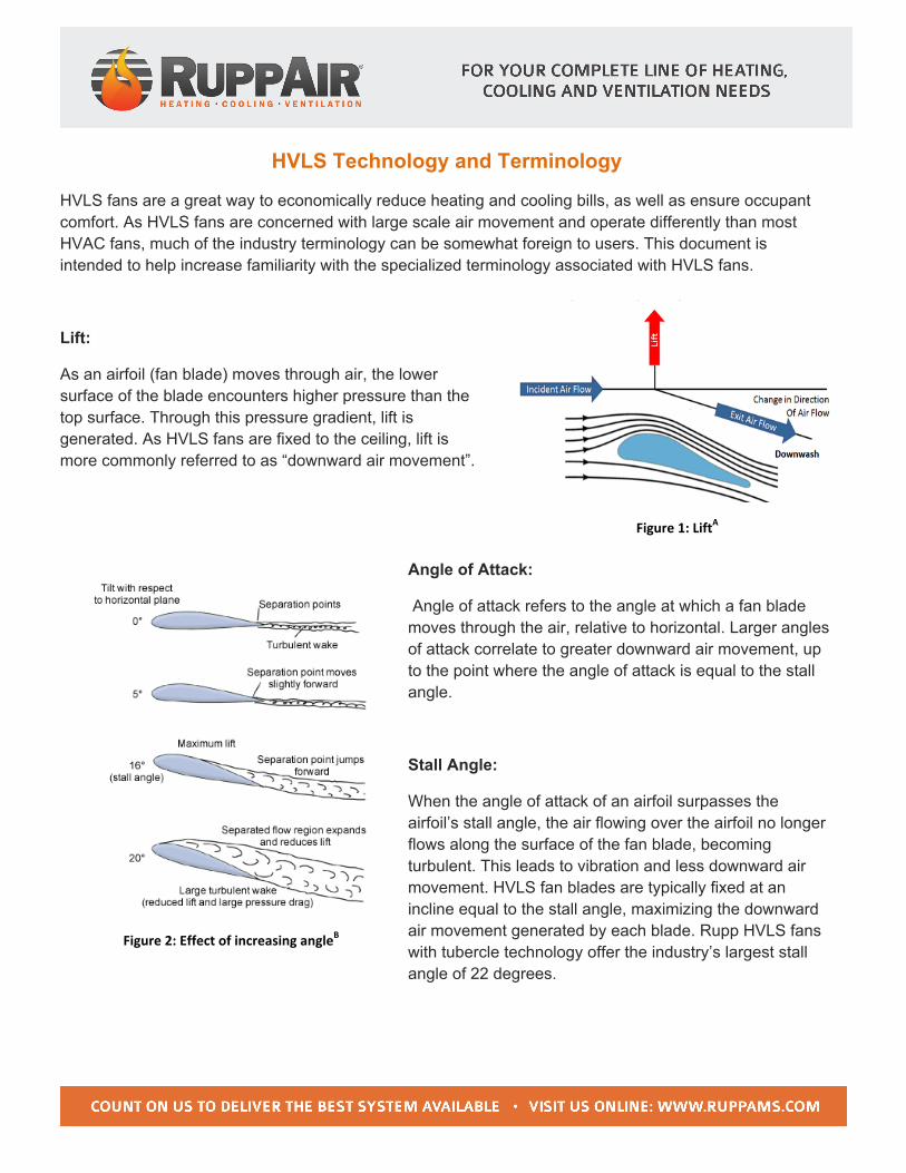
Figure 1: LiftA
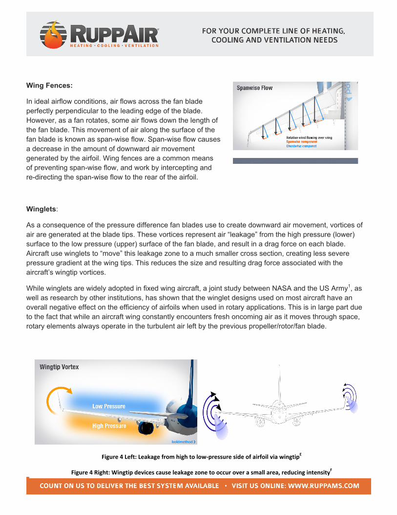
Figure 2: Effect of increasing angleB
HVLS Technology and Terminology
HVLS fans are a great way to economically reduce heating and cooling bills, as well as ensure occupant comfort. As HVLS fans are concerned with large scale air movement and operate differently than most HVAC fans, much of the industry terminology can be somewhat foreign to users. This document is intended to help increase familiarity with the specialized terminology associated with HVLS fans.
Lift:
As an airfoil (fan blade) moves through air, the lower surface of the blade encounters higher pressure than the top surface. Through this pressure gradient, lift is generated. As HVLS fans are fixed to the ceiling, lift is more commonly referred to as “downward air movement”.
Angle of Attack:
Angle of attack refers to the angle at which a fan blade moves through the air, relative to horizontal. Larger angles of attack correlate to greater downward air movement, up to the point where the angle of attack is equal to the stall angle.
Stall Angle:
When the angle of attack of an airfoil surpasses the airfoil’s stall angle, the air flowing over the airfoil no longer flows along the surface of the fan blade, becoming turbulent. This leads to vibration and less downward air movement. HVLS fan blades are typically fixed at an incline equal to the stall angle, maximizing the downward air movement generated by each blade. Rupp HVLS fans with tubercle technology offer the industry’s largest stall angle of 22 degrees.
Figure 3: Span-‐wise flowC and fixed-‐wing fencesD
Figure 4 Left: Leakage from high to low-‐pressure side of airfoil via wingtipE
Figure 4 Right: Wingtip devices cause leakage zone to occur over a small area, reducing intensityF
Wing Fences:
In ideal airflow conditions, air flows across the fan blade perfectly perpendicular to the leading edge of the blade. However, as a fan rotates, some air flows down the length of the fan blade. This movement of air along the surface of the fan blade is known as span-wise flow. Span-wise flow causes a decrease in the amount of downward air movement generated by the airfoil. Wing fences are a common means of preventing span-wise flow, and work by intercepting and re-directing the span-wise flow to the rear of the airfoil.
Winglets:
As a consequence of the pressure difference fan blades use to create downward air movement, vortices of air are generated at the blade tips. These vortices represent air “leakage” from the high pressure (lower) surface to the low pressure (upper) surface of the fan blade, and result in a drag force on each blade. Aircraft use winglets to “move” this leakage zone to a much smaller cross section, creating less severe pressure gradient at the wing tips. This reduces the size and resulting drag force associated with the aircraft’s wingtip vortices.
While winglets are widely adopted in fixed wing aircraft, a joint study between NASA and the US Army1, as well as research by other institutions, has shown that the winglet designs used on most aircraft have an overall negative effect on the efficiency of airfoils when used in rotary applications. This is in large part due to the fact that while an aircraft wing constantly encounters fresh oncoming air as it moves through space, rotary elements always operate in the turbulent air left by the previous propeller/rotor/fan blade.
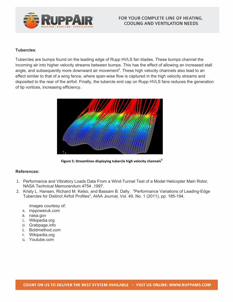
Figure 5: Streamlines displaying tubercle high velocity channelsG
Tubercles:
Tubercles are bumps found on the leading edge of Rupp HVLS fan blades. These bumps channel the incoming air into higher velocity streams between bumps. This has the effect of allowing an increased stall angle, and subsequently more downward air movement2. These high velocity channels also lead to an effect similar to that of a wing fence, where span-wise flow is captured in the high velocity streams and deposited to the rear of the airfoil. Finally, the tubercle end cap on Rupp HVLS fans reduces the generation of tip vortices, increasing efficiency.
References:
1. Performance and Vibratory Loads Data From a Wind-Tunnel Test of a Model Helicopter Main Rotor, NASA Technical Memorandum 4754 ,1997.
2. Kristy L. Hansen, Richard M. Kelso, and Bassam B. Dally. "Performance Variations of Leading-Edge Tubercles for Distinct Airfoil Profiles", AIAA Journal, Vol. 49, No. 1 (2011), pp. 185-194.
Images courtesy of: A. mppoweruk.com B. nasa.gov C. Wikipedia.org D. Grabpage.info E. Boldmethod.com F. Wikipedia.org G. Youtube.com Figure 6: Side down draft airflow


![Rupp Clary[1]](https://static.documents.pub/doc/80x56/545988f8af795998788b578b/rupp-clary1.jpg)


