Page 1
120
Creative Construction Conference 2016
Rutting Prediction of a Reinforced Cold Bituminous Emulsion
Mixture Using Finite Element Modelling
Hayder Kamil Shanbara1*, Felicite Ruddock2 and William Atherton3
1 PhD student, Department of Civil Engineering / Faculty of Engineering and Technology, Liverpool John Moores University, Liverpool,
UK, E-mail address: [email protected] or [email protected] ,
Tel: +44(0)7459394984 or +964(0)7902274877. Lecturer at Al-Muthanna University, Iraq 2 Programme Leader, Department of Civil Engineering / Faculty of Engineering and Technology, Liverpool John Moores University,
Liverpool, UK, E-mail address: [email protected] . 3 William Atherton, Programme Manager, Department of Civil Engineering, Faculty of Engineering and Technology, Liverpool John Moores
University, Liverpool, UK, E-mail address: [email protected] .
Abstract
A three-dimensional (3D) finite element (FE) model of a reinforced cold bituminous emulsion mixture (CBEM) was built in
order to investigate the effect of static wheel load on rutting formation and flexible pavement response. This model has been
developed to represent a four-layer pavement structure with elastic responses and to simulate the mechanical behaviour and
pavement performance under static load condition. Also, it is focused on the prediction of the contribution of glass fibre (as a
reinforcement material) in the surface course to develop the tensile and shear strength of flexible pavement. Preparation and
validation of the model were carried out in the pavement laboratory using experimental data. In this research, finite element
analyses have been conducted using ABAQUS software in which model dimensions, element types and meshing strategies are
taken to achieve a desired degree of accuracy and convergence of the developed model. In addition, this developed model has
been applied to CBEMs to investigate the effects of glass fibre on the performance of a reinforced pavement surface layer, as
well as to study the effects of this fibre to minimize the vertical surface deflection, and horizontal and vertical displacements
for the various courses. Finally, the FE model is capable of predicting surface damage to flexible pavement and its partial
recovery after application of load. The results demonstrate the capability of the model in simulating the effect of fibre on
vertical surface deflection (rutting), horizontal and vertical displacements in CBEM.
Keywords: ABAQUS, cold bitumen emulsion mixtures, rutting, three-dimensional finite element
1. Introduction
Permanent deformation (rutting) is one of the main important and significant damages encountered in flexible
pavement, Permanent deformation (rutting) is one of the main important and significant damages encountered in
flexible pavement, especially in the countries that have high temperature during the summer seasons. In all flexible
pavement layers, the accumulation of permanent deformation under the effect of traffic loading causes rutting. Rut
depth and width are mainly affected by structural properties of the pavement layers such as layers thickness,
material quality, traffic loads and temperature [1]. The ability of rutting or permanent deformation prediction in
flexible pavement is an essential part of pavement design. Therefore, some simplification hypotheses are often
performed for analysis and design such as the elastic behaviour of pavement material and isotropic nature. The
basic hypotheses of multi-layer pavement system include [2]:
_____________________________
* Hayder Kamil Shanbara. Tel.: +44(0)7459394984;
E-mail address: [email protected]
Page 2
121
Flexible pavement layers are homogeneous and isotropic.
Materials behaviour is elastic and linear.
Materials are massless.
Layer thickness is limited.
Load is uniformly distributed over a rectangular contact area.
Boundary conditions were considered that the contact between two layers is identical for both layers in term of
shear tension, vertical tension, vertical and radial displacements.
Some diagrams and tables have determined stress, strain and displacement in multi-layer system after proposing
these equations [3]. Finite element analysis is a numerical method to solve these equations.
The research objective is to develop a finite element model for an existing flexible pavement. This model would
be capable of predicting the stress and strain responses of the elastic pavement and the output of the model is the
prediction of permanent deformation (rutting).
2. Classical rutting prediction approach
Classic attempts to model rutting analysis are concentrated on protecting the under layers. At the top of the
subgrade layer, the vertical stress and strain are limited to control the permanent deformation of the whole
pavement structure and also restricted the tensile stress and strain at the bottom of the lowest bituminous layer to
control fatigue cracks [4]. A classic model of rutting prediction utilized in road pavement analysis is given in [4] :
𝑁𝑓 = 1.077 × 10¹⁸ (10−6 ÷ 휀𝑣)4.4843 (1)
Where:
Nf : applied load (kN).
εv : vertical compressive strain at the top of subgrade layer.
Nowadays, comprehensive researches have been carried out using different laboratory test methods such as
wheel tracking test, creep test, complex (dynamic) modulus test and triaxial test, combined with contributions from
investigations of pavement field rutting [4]. It was noticed that rutting failure was not solely occurring in subgrade
layer or other under layers but also can be as a result of bituminous mixture problems. Consequently, it has become
obvious that in accurate road pavement design procedure, the cumulative permanent deformation in all pavement
layers must be considered.
Three model types have been used to compute permanent deformation in flexible pavement: empirical,
mechanistic empirical and fully mechanistic. The empirical model is the simplest mathematical form fitted to
controlled field data depending on regression equations. Properties of materials and site conditions are not included
in this type of modelling whilst specific applications, for instance performance predictions in system of road
pavement management are commonly used. The main purpose of this model is to evaluate future performance
based only on the recorded deformation history.
The mechanistic empirical model is designed based on a combination of predictions of simple mechanistic
response (usually using theory of elasticity) with empirical equations which are calibrated by experimental tests.
The computed mechanistic response is utilized as input in the empirical model to predict actual performance, such
as rutting and cracking. The effect of traffic loading and environmental conditions can be involved. Throughout
application, the model mechanistic response is obtained during a pavement structural analysis. The linear elastic
theory is usually used for its formulation and fast computer analysis.
Fully mechanistic models to compute or predict permanent deformation also use a structural analysis program
to show the effect of the stresses and strains in the road pavement structure due to the influence of loading time
(frequency) and temperature. The different characteristics of material behaviour are represented using constitutive
models to directly predict rutting, cracking and other types of damage. With the most important points of these
models, the effect of various load conditions, for example loading time, value and temperature can be simply
evaluated and incorporated into these models. Because of capabilities of mechanistic models to predict road
pavement distresses, there is no need for empirical functions. However, constitutive mechanistic models are
complex and have some difficulties in calibration and execution. Very limited researches have been carried out to
fulfil mechanistic models to predict behaviour of asphalt mixtures.
Page 3
122
3. Materials and methods
Materials
The materials used in this research work are briefly introduced as follows:
3.1.1. Aggregate
A crushed granite aggregate both coarse and fine aggregate was used in this research which is normally used to
produce Asphalt Concrete hot mix. The main properties of the aggregate together with the traditional mineral filler
(limestone) used are presented in Table 1. The aggregate grading was asphalt concrete close graded surface course
which is a prominent type of asphalt surface layer material, as shown in Figure 1 of mixtures (cold and hot) which
are in accordance with BS EN 13108-1[5].
Table 1. Physical properties of the aggregate.
Figure 1. 14mm close graded surface course.
3.1.2. Bitumen emulsion and bitumen
A slow-setting cationic emulsion (cold asphalt binder (CAB50)) that contains 50% residual bitumen of 50/70
pen grade based bitumen was used throughout this study for the cold mixtures as its properties are shown in Table
2. This bitumen emulsion was chosen to obtain high adhesion between aggregate particles.
Table 2. Properties of (CAB50) bitumen emulsion.
Description (CAB) bitumen emulsion
Type Cationic
Appearance Black to dark brown liquid
Base bitumen 50/70 pen
Bitumen content 50 %
Boiling point, oC 100 oC
Relative density at 15 oC, g/ml 1.05
0
20
40
60
80
100
120
0,01 0,1 1 10 100
Cu
mu
lati
ve p
erce
nta
ge p
assi
ng
(%)
Sieve size (mm)
Upper limit
Lower limit
Aggregate used
Properties Value
Coarse aggregate:
Bulk specific gravity (g/cm3) 2.78
Apparent specific gravity (g/cm3) 2.83
Water absorption (%) 0.6
Fine aggregate:
Bulk specific gravity (g/cm3) 2.68
Apparent specific gravity (g/cm3) 2.71
Water absorption (%) 1.5
Page 4
123
3.1.3. Filler and fibre
One filler type was used in this study, traditional mineral filler. Glass fibre was used in this study and it presents
interesting properties as a reinforcing material. It is both strong and flexible. It is thermally and chemically stable
at bituminous mixture temperatures of 200°C. It is not affected by de-icing salt, petroleum or bitumen. Glass fibre
has a Young’s modulus almost 20 times higher than typical bituminous modulus at around 20°C [6] and has a high
tensile strength.
Sample preparation and conditioning
The design procedure followed the method adopted by the Asphalt Institute, (Marshall Method for Emulsified
Asphalt Aggregate Cold Mixture Design (MS-14), 1989) for designing the cold asphalt mixtures. Incorporation of
the fibre was achieved through partial substitution of the conventional aggregate. Glass fibre as a reinforcement
material was the material that was added to the mixture. In order to find the optimum content and length of the
glass fibre, cold bituminous emulsion mixtures (CBEMs) were treated according to fibre weight with 0.25, 0.35
and 0.50% of total aggregate weight and 10, 14 and 20 mm long. The testing results supported that 0.35% fibre
content and 14 mm long gave the best results in term of Indirect Tensile Stiffness Modulus (ITSM). Compaction
was carried out by means of a Marshall hammer with 50 blows applied to each face of the specimen. Cold mixtures
are evolutional in nature, where the mixtures’ strength characteristics are very sensitive to curing time and
temperature.
Method
The fundamental test that was used is the Indirect Tensile Stiffness Modulus (ITSM): The test was conducted
in accordance with BS EN 12697-26 [7], using Cooper Research Technology HYD 25 testing apparatus. The test
conditions are as in Table 3.
Table 3. ITSM Test Conditions.
4. Finite element modeling
After designing the conventional and reinforced CBEMs, stiffness modulus tests were carried out at two and
seven days curing time as shown in Table 4.
Table 4. ITSM of the conventional mix.
Curing time (days) ITSM (MPa)
Conventional Reinforced
2 278 723
7 366 1060
Model geometry
The flexible pavement geometric model is created by using discrete parts which each part represent one
structural pavement layer in the ABAQUS solid modeler. The geometric model is constructed in three dimensions
(3D) finite element with a single axle which is assumed symmetrical on the surface of pavement in traffic direction.
Model dimensions are used to avoid any edge effect errors, while having acceptable limits of elements’ size.
item range
Specimen diameter mm 100 ± 3
Rise time 124 ± 4 ms
Transient peak horizontal deformation 5 µm
Loading time 3-300 s
Poisson’s ratio 0.35
No. of conditioning plus 5
No. of test plus 5
Test temperature °C 20 ± 0.5
Specimen thickness mm 63± 3
compaction Marshall 50×2
Specimen temp. conditioning 4hr before testing
Page 5
124
Pavement cross-section is shown in Figure 2, four types of layers: cold bituminous emulsion mixture as a surface
course, granular base, granular subbase and subgrade are performed to simulate the road pavement structure. All
layers have the same shape to keep the nodes continuity between successive layers.
Figure 2 Pavement cross-section.
Boundary condition
Boundary conditions are employed to all edges or faces of the structural pavement geometric model to control
displacement in the horizontal direction on the vertical edge which is perpendicular to the layer surface. The last
layer (subgrade) modelling is assumed to be fixed with no displacement in horizontal and vertical directions
representing a very stiff layer (encastre). The geometric model is symmetrical on x and y axes, therefore, quarter
of the model is taken and the load is applied as shown in Figure 3.
Figure 3. Boundary condition and load.
10 cm CBEM
15 cm granular base
20 cm granular subbase
30 cm subgrade
Page 6
125
Meshing and element definition
The meshing process divides the body into many finite elements jointed at shared nodes. The accuracy of results
depends on the density of the elements in a known area of the body. For instance, high density is preferred around
the loading area and underneath the wheel path in the case of simulating a flexible pavement subjected to a tyre
load, to improve the level of accuracy. However, computational time will be longer if more elements are there. It
is significant to restrict the number of finite elements. In order to obtain asuitable mesh size, several iterations of
finite element analyses are ideally performed with decreasing the element number for meshing a pavement
structure. It will provide an adequately precise solution at a sufficient computational effort.
Through the mashing process, the element type and nodes number should be defined. Simple 8-node brick
elements in three dimensional finite element model, which is selected to use in the analysis, or 4-node quadrilateral
elements in two dimensions are allowing linear approximations of the movements between the corner nodes. Some
elements have more nodes at the midpoint of each edge which will accommodate higher order approximating
polynomials and the computational effort will increase significantly. Therefore, the most common way is utilizing
simple finite elements and increase the density in areas of high preferred accuracy.
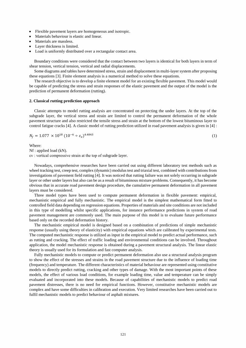
Figure 4 shows the plan view of the pavement surface. The tyre imprint area is modelled as a 29 x 20 mm
rectangular area. The vertical and horizontal lines define the different meshing areas. The static load area is shown
in the centre at which the most refined mesh is defined. All pavement layers are simulated with the same shape
configuration. After completing zone configuration, a mesh study is carried out to find the optimal mesh density
for each zone. Figure 5 shows the final mesh for the top surface layer. A denser mesh is employed in zones near
to the load, whilst a relatively coarser mesh is used further away from the loading zones in both directions.
Figure 4. Pavement surface plan. Figure 5. The final mesh of the top surface layer.
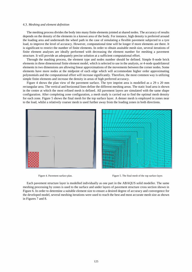
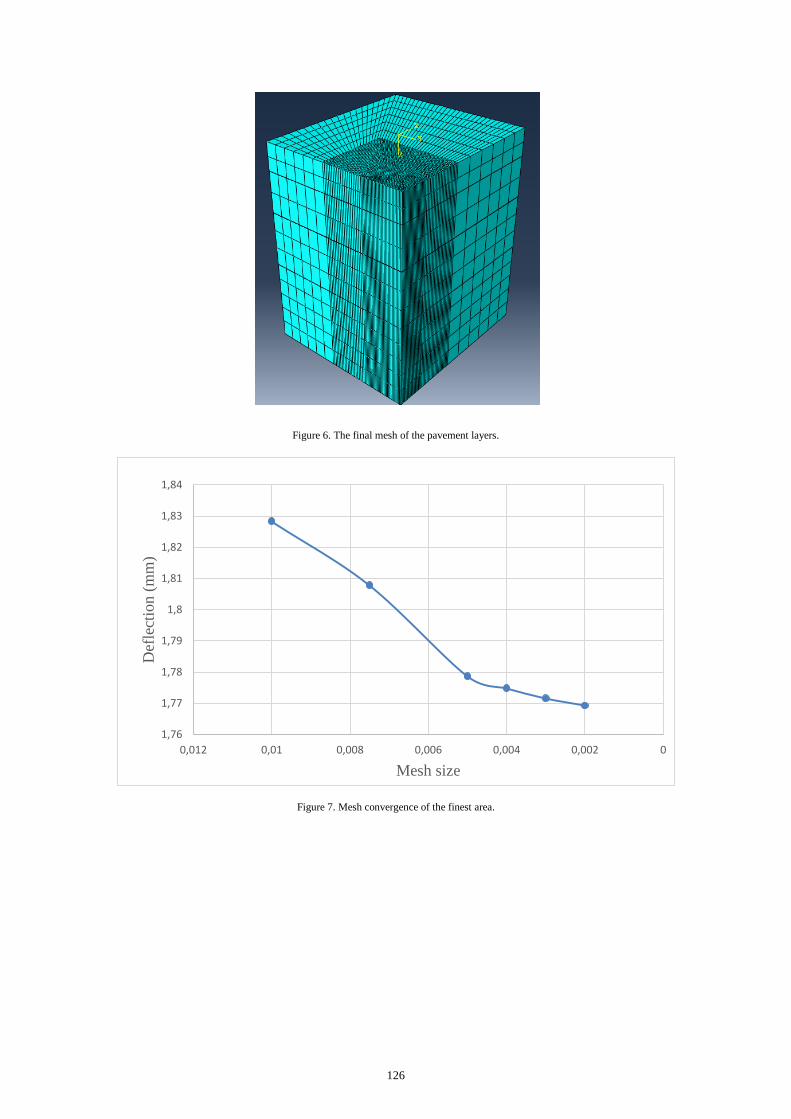
Each pavement structure layer is modelled individually as one part in the ABAQUS solid modeller. The same
meshing processing by zones is used to the surface and under layers of pavement structure cross section shown in
Figure 6. In order to determine a suitable element size to ensure a desired degree of accuracy and convergence for
the developed model, several meshing iterations were used to reach the best and most accurate mesh size as shown
in Figures 7 and 8.
Page 7
126
Figure 6. The final mesh of the pavement layers.
Figure 7. Mesh convergence of the finest area.
1,76
1,77
1,78
1,79
1,8
1,81
1,82
1,83
1,84
00,0020,0040,0060,0080,010,012
Def
lect
ion (
mm
)
Mesh size
Page 8
127
Figure 8. Mesh convergence of the middle area.
Material properties
In this stage of this report, all pavement material behaviours are modelled to be homogeneous isotropic linearly
elastic responding to the applied load as static load. Experimental tests are carried out on CBEM after two days of
curing as a conventional mix (without reinforcement) to obtain elastic properties of bituminous mixtures. The other
layers are assumed granular base, granular subbase and subgrade and their properties were obtained from [8]. The
elastic material properties are shown in Table 5.
Table 5. Elastic material properties.
Layer Modulus of Elasticity (E)
(MPa)
Poisson’s ratio Density (kg/m3)
Surface 278 0.4 2200
Granular base 200 0.35 2000
Granular subbase 100 0.35 1800
Subgrade 50 0.3 1700
Load application
The prescribed applied load of the problem can be from forces, pressures or displacements for pavement
structural analysis. In the loaded area, which is rectangular, pressure load is applied directly to the nodes and
transformed into nodal forces as shown in Figure 3. In this report to simulate the static wheel load, a linear loading
increment from zero to the maximum known value is performed.
Rahman, Mahmud [9] presents that tyre imprint area has to be a rectangular area which is more suitable than
circular or ellipsoid tyre imprint areas. Also, this study shows that the tyre pressure is uniformly distributed over
the contact area. The tyre imprint pressure load, which applied directly on the finite elements underneath the wheel
path, is performed as 0.7 MPa (100 psi) which is to a single axial wheel load (40 KN) divided to the contact tyre
footprint area (58000 mm2).
5. Finite element simulation analysis
The parameters studied in this report are the vertical deflection of the pavement layers under the centre of the
load and the vertical surface deflection (deformation) of the top of the surface layer (CBEM) in two dimensions.
The top of the surface layer and the cross-sectional view of the pavement after applying the load are shown in
1,3
1,31
1,32
1,33
1,34
1,35
1,36
1,37
1,38
1,39
00,0050,010,0150,020,0250,030,0350,040,045
Def
lect
ion (
mm
)
Mesh size
Page 9
128
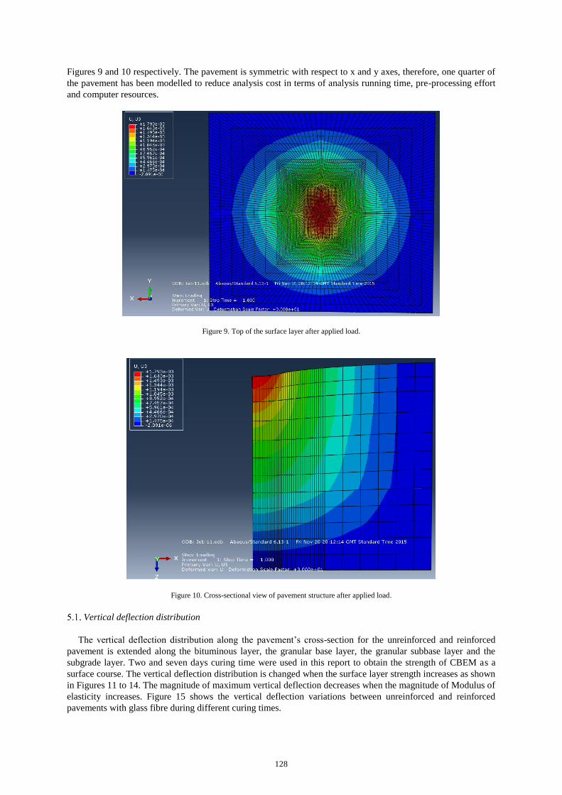
Figures 9 and 10 respectively. The pavement is symmetric with respect to x and y axes, therefore, one quarter of
the pavement has been modelled to reduce analysis cost in terms of analysis running time, pre-processing effort
and computer resources.
Figure 9. Top of the surface layer after applied load.
Figure 10. Cross-sectional view of pavement structure after applied load.
Vertical deflection distribution
The vertical deflection distribution along the pavement’s cross-section for the unreinforced and reinforced
pavement is extended along the bituminous layer, the granular base layer, the granular subbase layer and the
subgrade layer. Two and seven days curing time were used in this report to obtain the strength of CBEM as a
surface course. The vertical deflection distribution is changed when the surface layer strength increases as shown
in Figures 11 to 14. The magnitude of maximum vertical deflection decreases when the magnitude of Modulus of
elasticity increases. Figure 15 shows the vertical deflection variations between unreinforced and reinforced
pavements with glass fibre during different curing times.
Page 10
129
Figure 11. The vertical deflection distribution along the pavement’s cross-section for the unreinforced pavement after 2 days curing.
Figure 12. The vertical deflection distribution along the pavement’s cross-section for the unreinforced pavement after 7 days curing.
Figure 13. The vertical deflection distribution along the pavement’s cross-section for the glass fibre reinforced pavement after 2 days curing.
Page 11
130
Figure 14. The vertical deflection distribution along the pavement’s cross-section for the glass fibre reinforced pavement after 7 days curing.
Figure 15. The vertical deflection variations between the unreinforced and reinforced pavement by glass fibre with different curing times.
6. Conclusion
It can be concluded that the highest reduction of the vertical deflection is achieved for pavement with 0.35%
glass fibre after 7 days of curing time. This reduction, which reaches nearly 59%, is achieved when the stiffness
modulus increased from 278 MPa for unreinforced pavement to 1060 MPa for pavement reinforced with glass
fibre.
Acknowledgements
The first author wishes to express his sincere gratitude to the Itaqi Ministry of Higher Education and Scientific
Research and Al-Muthanna University in Iraq for providing the financial support. The authors also thank David
Jobling-Purser, Steve Joyce, Neil Turner and Richard Lavery who helped the authors a lot to complete this study.
References
[1] Khateeb, L.A., A. Saoud, and M.F. Al-Msouti, Rutting Prediction of Flexible Pavements Using Finite Element Modeling. Jordan
Journal of Civil Engineering, 2011. 5.
[2] Salehabadi, E.G., The Linear Elastic Analysis of Flexible Pavement by the Finite Element Method and Theory of Multiple-Layers
System. Switzerland Research Park Journal, 2012. 101.
[3] Abtahi, S.M., M. Sheikhzadeh, and S.M. Hejazi, Fiber-reinforced asphalt-concrete – A review. Construction and Building Materials,
2010. 24(6): p. 871-877.
0
0,2
0,4
0,6
0,8
1
1,2
1,4
1,6
1,8
0 10 20 30 40 50 60 70 80
Def
lect
ion (
mm
)
Depth (cm)
Unreinforced pavement & 2days curing
Unreinforced pavement & 7days curing
Glass fibre reinforced pavement& 2 days curing
Glass fibre reinforced pavement& 7 days curing
Page 12
131
[4] Uzarowski, L., The Development of Asphalt Mix Creep Parameters and Finite Element Modeling of Asphalt Rutting, in Civil
Engineering. 2006, University of Waterloo.
[5] European Committee for Standardization, Bituminous mixtures materials specification-Asphalt Concrete, in British Standard Institution,
BS EN 13108: part 1. 2006: London, UK.
[6] Nguyen, M.L., et al., Review of glass fibre grid use for pavement reinforcement and APT experiments at IFSTTAR. Road Materials and
Pavement Design, 2013. 14.
[7] British Standard Institution, BS EN 1267-26 Bituminous mixturs Test methods for hot mix asphalt-part 26 Stiffness. 2004: London,UK.
[8] Junior, F.E., E.P. Junior, and J.B. Soares, Viscoelastic and elastic structural analysis of flexible pavements. Center for Parallel
Computations and Department of Civil Engineering, 2005.
[9 ] Rahman, M.T., K. Mahmud, and S. Ahsan, Stress Strain characteristics of flexible pavement using Finite Element analysis.
International Journal of Civil and Structural Engineering, 2011. 2.