Petroleum & Petrochemical Engineering Journal ISSN: 2578-4846 MEDWIN PUBLISHERS Commied to Create Value for Researchers Salt Deposition in Electric Submersible Centrifugal Pumps under Intermittent Operation Pet Petro Chem Eng J Salt Deposition in Electric Submersible Centrifugal Pumps under Intermittent Operation Gareev AA* Niznesortymskneft Oil & Gas Production Division, Russia *Corresponding author: Adib Gareev, Niznesortymskneft Oil-and-Gas Production, Direktorate Surgut, Tyumtn region, 628447, Russia, Tel: 89324141618; Email: [email protected]Review Article Volume 5 Issue 2 Received Date: May 21, 2021 Published Date: June 29, 2021 DOI: 10.23880/ppej-16000267 Abstract “Salt deposition in a centrifugal pump under intermittent operation” is the first article to address the cause of failures among electric submersible centrifugal pumps operating intermittently. The causes of said failures are analyzed. The failure of electric submersible centrifugal pumps is caused by their temperature behavior during operation. The problem of the thermal condition of a centrifugal pump under intermittent operation must be solved. Moreover, the number of failures caused by salt deposition or the electric resistance drop of the “cable – motor” system can be reduced. Keywords: Oil production; Centrifugal pumps in oil production; Discontinuous operation of a centrifugal pump; Salt deposition problem under discontinuous operation Electric Submersible Centrifugal Pumps The electric submersible centrifugal pumps (further referred to as ESP) used in oil production are normally in service for a long period of time. Over the course of operation of an individual oil well a change in reservoir energy occurs, leading to a reduction in well-production rate. An ESP unit operating in optimal mode drifts to the “right-hand area of the head and rate” (Figure 1). Production rate (Qv) values are shown on the Y-axis, while the X-axis displays the head (Н, pressure) created by the pump at the standard 50Hz frequency. The optimal operating range is shown in blue. The green arrow illustrates the change in direction of the ESP unit’s operating mode in case of a well-production drop. Figure 1: ESP unit head and rate. The main purpose here is to ensure the ESP’s operation within the optimal performance range.
MEDWIN PUBLISHERSCommitted to Create Value for Researchers
Salt Deposition in Electric Submersible Centrifugal Pumps under Intermittent Operation Pet Petro Chem Eng J
Salt Deposition in Electric Submersible Centrifugal Pumps under Intermittent Operation
Gareev AA*Niznesortymskneft Oil & Gas Production Division, Russia *Corresponding author: Adib Gareev, Niznesortymskneft Oil-and-Gas Production, Direktorate Surgut, Tyumtn region, 628447, Russia, Tel: 89324141618; Email: [email protected]
Review ArticleVolume 5 Issue 2
Received Date: May 21, 2021
Published Date: June 29, 2021
DOI: 10.23880/ppej-16000267
Abstract
“Salt deposition in a centrifugal pump under intermittent operation” is the first article to address the cause of failures among electric submersible centrifugal pumps operating intermittently. The causes of said failures are analyzed. The failure of electric submersible centrifugal pumps is caused by their temperature behavior during operation. The problem of the thermal condition of a centrifugal pump under intermittent operation must be solved. Moreover, the number of failures caused by salt deposition or the electric resistance drop of the “cable – motor” system can be reduced.
Keywords: Oil production; Centrifugal pumps in oil production; Discontinuous operation of a centrifugal pump; Salt deposition problem under discontinuous operation
Electric Submersible Centrifugal Pumps
The electric submersible centrifugal pumps (further referred to as ESP) used in oil production are normally in service for a long period of time. Over the course of operation of an individual oil well a change in reservoir energy occurs, leading to a reduction in well-production rate. An ESP unit operating in optimal mode drifts to the “right-hand area of
the head and rate” (Figure 1). Production rate (Qv) values are shown on the Y-axis, while the X-axis displays the head (Н, pressure) created by the pump at the standard 50Hz frequency. The optimal operating range is shown in blue. The green arrow illustrates the change in direction of the ESP unit’s operating mode in case of a well-production drop.
Figure 1: ESP unit head and rate. The main purpose here is to ensure the ESP’s operation within the optimal performance range.
That said, ESP suction pressure switches from optimal to permissible and, all too often, can drift into the critical pressure range [1-4]. The ESP’s transition into the permissible suction pressure range causes its temperature rise [5]. The pump’s temperature rise leads to various operational problems and the ultimate breakdown of the unit due to R=0 (the electrical insulation resistance drop of the “cable
– motor” system to 0 Mohm) or salt deposition. Controlling salt deposition entails the introduction of various processes. The ESP’s time between failures (TBF) decreases as a result of the high temperature’s impact [1,6].
Table 1 shows the mean time between failures (MTBF) of the dismantled units.
By Type of FailureMTBF of ESP units by output rate
Per the data presented in Table 3, only 56% (21+21+14) of the ESP units’ failures were caused by their operation in the right-hand area of head and rate.
The fault-tolerance problem of ESP units is aggravated by the rapid growth of the well stock equipped with ESP units and necessarily set to automatic reclosing mode (Figure 2). The physics of automatic reclosing mode entail the periodic shutdown of the ESP for cooling purposes so as to avoid its failure due to R=0 (melting of the flat cable with a thermal-resistant insert) or its jamming due to salt deposition.
The necessity of studying ESP operation in automatic reclosing mode is clearly confirmed by Table 4. Per the data presented in Table 4, the number of ESPs running in automatic reclosing mode has more than tripled since 2017, and this trend is likely to continue given the measures being taken to enhance the maximum efficient rate of oil fields. Apart from automatic reclosing mode there’s also short-burst operating
mode in which, over the course of an hour, the ESP unit starts for a while and then stops again while waiting for the fluid to accumulate.
Figure 2: Change in the well stock with ESP units running in automatic reclosing mode, by year.
Well Number ESP Нсп., M TBF,
Days
Flow Rate, CMPD
(M3/D)
Water Cut, %
Н Дин. (Dynamic
Fluid Level), M
Mode, Running Time / Fluid
Accumulation Time
Cause Of Failure In Automatic
Reclosing Mode
1st well50-2100* 2,340 506 7 3 1,686 20 min /
40 min R=0
50-2100* 2,540 343 5 3 1,810 8 min / 42 min in operation
2nd well 35-1800 2,450 169 7 32 2,200 6 h / 6 h NR
50-2000* 2,450 379 7 40 2,300 30 min / 30 min NR
50-1900* 2,450 138 6 42 2,200 20 min / 40 min NR
50-1900* 2,320 184 8 43 2,100 25 min / 35 min NR
35-2050 2,430 130 7 45 1,680 60 min / 60 min NR
50-1900* 2,320 182 5 51 1,570 1 h / 3 h NR35-1800
2,320223
769
1,680 1 h / 5 h in operation
Note: h – hour, min – minute, * – short-burst operating mode
Table 4: TBF of ESP units in short-burst operating mode and automatic reclosing mode.
We can observe from Table 4 that the ESP failures are caused by their operation under high temperatures; e.g. the first ESP unit in the 1st well broke down due to the melting of the flat cable with a thermal-resistant [1,7,8] insert whose
operating temperature was 230°С. The pump temperature reached 300°С and may have even exceeded that value until the failure occurred due to melting and the electric resistance drop of the “cable – motor” system to 0 Mohm.
Salt deposition in the first ESP unit in the 1st well was negligible, as the water cut was just 3%. The failures of the remaining units in the 2nd well were caused by the high water cut of the well (between 32 and 69%) – the pumped gas, water and oil mixture boiled in the pump during each startup [1].
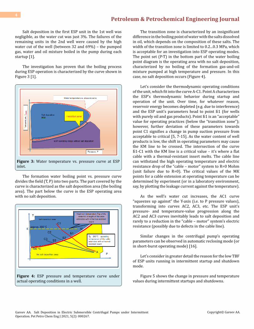
The investigation has proven that the boiling process during ESP operation is characterized by the curve shown in Figure 3 [1].
Figure 3: Water temperature vs. pressure curve at ESP inlet.
The formation water boiling point vs. pressure curve divides the field (Т, Р) into two parts. The part covered by the curve is characterized as the salt deposition area (the boiling area). The part below the curve is the ESP operating area with no salt deposition.
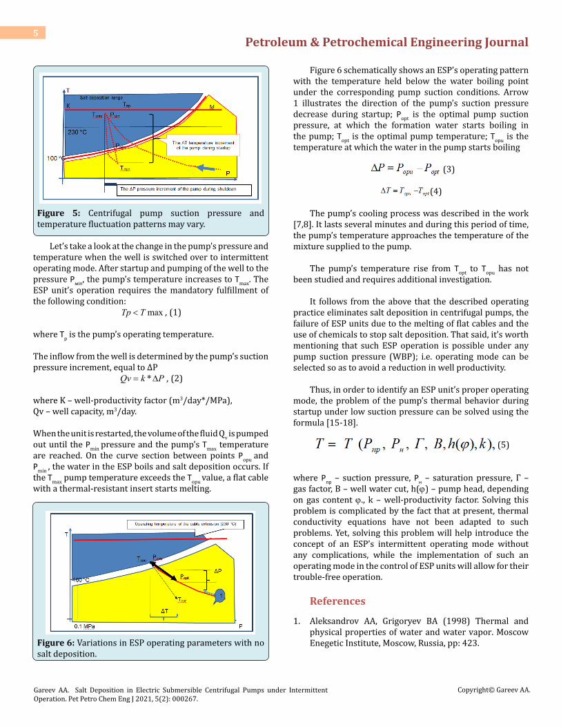
Figure 4: ESP pressure and temperature curve under actual operating conditions in a well.
The transition zone is characterized by an insignificant difference in the boiling point of water with the salts dissolved in oil, which depends on the composition of these salts. The width of the transition zone is limited to 0.2...0.3 MPa, which is acceptable for an investigation into ESP operating modes. The point set (Р-Т) in the bottom part of the water boiling point diagram is the operating area with no salt deposition, characterized by no boiling of the formation gas-and-oil mixture pumped at high temperature and pressure. In this case, no salt deposition occurs (Figure 4).
Let’s consider the thermodynamic operating conditions of the unit, which fit into the curve А-С1. Point A characterizes the ESP’s thermodynamic behavior during startup and operation of the unit. Over time, for whatever reason, reservoir energy becomes depleted (e.g. due to interference) and the ESP unit’s parameters head to point Б1 (for wells with purely oil and gas products). Point Б1 is an “acceptable” value for operating practices (below the “transition zone”); however, further deviation of these parameters towards point C1 signifies a change in pump suction pressure from acceptable to critical [5, 7-15]. As the water content of well products is low, the shift in operating parameters may cause the КМ line to be crossed. The intersection of the curve Б1-С1 with the КМ line is a critical value – it’s where a flat cable with a thermal-resistant insert melts. The cable line can withstand the high operating temperature and electric resistance drop of the “cable – motor” system to R=0 Mohm (unit failure due to R=0). The critical values of the МК points for a cable extension at operating temperature can be determined by experiment (or in a laboratory environment, say, by plotting the leakage current against the temperature).
As the well’s water cut increases, the АС1 curve “squeezes up against” the Y-axis (i.e. to P pressure values), transforming into curves АС2, АС3, etc. The ESP unit’s pressure- and temperature-value progression along the АС2 and АС3 curves inevitably leads to salt deposition and rarely to a reduction in the “cable – motor” system’s electric resistance (possibly due to defects in the cable line).
Similar changes in the centrifugal pump’s operating parameters can be observed in automatic reclosing mode (or in short-burst operating mode) [16].
Let’s consider in greater detail the reason for the low TBF of ESP units running in intermittent startup and shutdown mode.
Figure 5 shows the change in pressure and temperature values during intermittent startups and shutdowns.
Figure 5: Centrifugal pump suction pressure and temperature fluctuation patterns may vary.
Let’s take a look at the change in the pump’s pressure and temperature when the well is switched over to intermittent operating mode. After startup and pumping of the well to the pressure Рмin, the pump’s temperature increases to Тmax. The ESP unit’s operation requires the mandatory fulfillment of the following condition:
maxTp T< , (1)
where Тр is the pump’s operating temperature.
The inflow from the well is determined by the pump’s suction pressure increment, equal to ΔР
*Qv k P= ∆ , (2)
where K – well-productivity factor (m3/day*/MPa), Qv – well capacity, m3/day.
When the unit is restarted, the volume of the fluid Qv is pumped out until the Рmin pressure and the pump’s Тmax temperature are reached. On the curve section between points Рopu and Рmin , the water in the ESP boils and salt deposition occurs. If the Тmax pump temperature exceeds the Тopu value, a flat cable with a thermal-resistant insert starts melting.
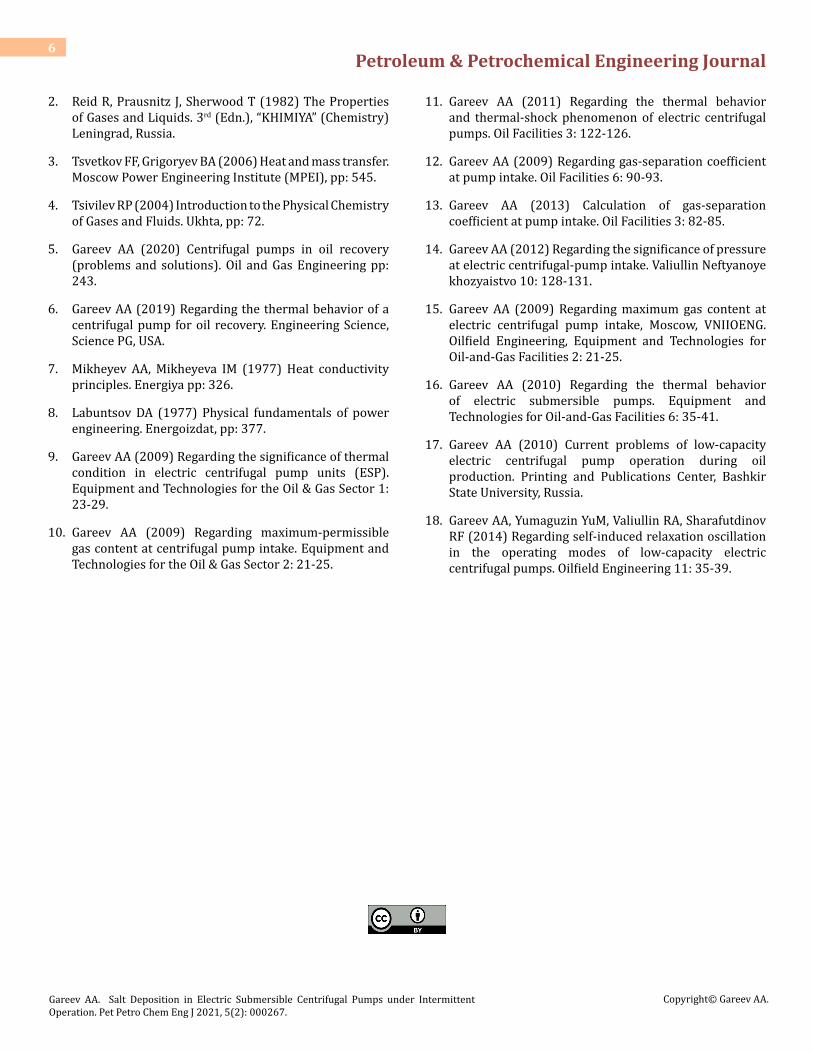
Figure 6: Variations in ESP operating parameters with no salt deposition.
Figure 6 schematically shows an ESP’s operating pattern with the temperature held below the water boiling point under the corresponding pump suction conditions. Arrow 1 illustrates the direction of the pump’s suction pressure decrease during startup; Рopt is the optimal pump suction pressure, at which the formation water starts boiling in the pump; Тopt is the optimal pump temperature; Тopu is the temperature at which the water in the pump starts boiling
(3)
(4)
The pump’s cooling process was described in the work [7,8]. It lasts several minutes and during this period of time, the pump’s temperature approaches the temperature of the mixture supplied to the pump.
The pump’s temperature rise from Тopt to Тopu has not been studied and requires additional investigation.
It follows from the above that the described operating practice eliminates salt deposition in centrifugal pumps, the failure of ESP units due to the melting of flat cables and the use of chemicals to stop salt deposition. That said, it’s worth mentioning that such ESP operation is possible under any pump suction pressure (WBP); i.e. operating mode can be selected so as to avoid a reduction in well productivity.
Thus, in order to identify an ESP unit’s proper operating mode, the problem of the pump’s thermal behavior during startup under low suction pressure can be solved using the formula [15-18].
(5)
where Рпр – suction pressure, Рн – saturation pressure, Г – gas factor, В – well water cut, h(ϕ) – pump head, depending on gas content ϕ., k – well-productivity factor. Solving this problem is complicated by the fact that at present, thermal conductivity equations have not been adapted to such problems. Yet, solving this problem will help introduce the concept of an ESP’s intermittent operating mode without any complications, while the implementation of such an operating mode in the control of ESP units will allow for their trouble-free operation.
References
1. Aleksandrov АА, Grigoryev ВА (1998) Thermal and physical properties of water and water vapor. Moscow Enegetic Institute, Moscow, Russia, pp: 423.
2. Reid R, Prausnitz J, Sherwood T (1982) The Properties of Gases and Liquids. 3rd (Edn.), “KHIMIYA” (Chemistry) Leningrad, Russia.
3. Tsvetkov FF, Grigoryev BA (2006) Heat and mass transfer. Moscow Power Engineering Institute (MPEI), pp: 545.
4. Tsivilev RP (2004) Introduction to the Physical Chemistry of Gases and Fluids. Ukhta, pp: 72.
5. Gareev АА (2020) Centrifugal pumps in oil recovery (problems and solutions). Oil and Gas Engineering pp: 243.
6. Gareev АА (2019) Regarding the thermal behavior of a centrifugal pump for oil recovery. Engineering Science, Science PG, USA.
7. Mikheyev AA, Mikheyeva IM (1977) Heat conductivity principles. Energiya pp: 326.
8. Labuntsov DA (1977) Physical fundamentals of power engineering. Energoizdat, pp: 377.
9. Gareev АА (2009) Regarding the significance of thermal condition in electric centrifugal pump units (ESP). Equipment and Technologies for the Oil & Gas Sector 1: 23-29.
10. Gareev АА (2009) Regarding maximum-permissible gas content at centrifugal pump intake. Equipment and Technologies for the Oil & Gas Sector 2: 21-25.
11. Gareev АА (2011) Regarding the thermal behavior and thermal-shock phenomenon of electric centrifugal pumps. Oil Facilities 3: 122-126.
13. Gareev AA (2013) Calculation of gas-separation coefficient at pump intake. Oil Facilities 3: 82-85.
14. Gareev AA (2012) Regarding the significance of pressure at electric centrifugal-pump intake. Valiullin Neftyanoye khozyaistvo 10: 128-131.
15. Gareev АА (2009) Regarding maximum gas content at electric centrifugal pump intake, Moscow, VNIIOENG. Oilfield Engineering, Equipment and Technologies for Oil-and-Gas Facilities 2: 21-25.
16. Gareev АА (2010) Regarding the thermal behavior of electric submersible pumps. Equipment and Technologies for Oil-and-Gas Facilities 6: 35-41.
17. Gareev АА (2010) Current problems of low-capacity electric centrifugal pump operation during oil production. Printing and Publications Center, Bashkir State University, Russia.
18. Gareev AA, Yumaguzin YuM, Valiullin RA, Sharafutdinov RF (2014) Regarding self-induced relaxation oscillation in the operating modes of low-capacity electric centrifugal pumps. Oilfield Engineering 11: 35-39.