Date: November 9, 2016 Project No.: 187-25-1 Prepared For: Mr. Chuck Anderson, P.E. SCHAAF & WHEELER CONSULTING ENGINEERS, INC. 1171 Homestead Road, Suite 255 Santa Clara, California 95050 Re: Updated Geotechnical Recommendations Poplar Avenue Pump Station Replacement East Poplar Avenue San Mateo, California Dear Mr. Anderson: As requested, this letter presents our updated geotechnical recommendations for the above referenced stormwater pump station replacement project. As you know, TRC Lowney previously prepared a geotechnical investigation report for the project (referenced below). This letter is intended to update the referenced geotechnical investigation report. We have performed our scope of work in accordance with our agreement dated February 15, 2014. For our use, we were provided with the following documents: Project plans titled, “City of San Mateo, Poplar Avenue Pump Station Replacement, Sheets C1 through C7, C11 through C28, M3, and M4,” prepared by Schaaf & Wheeler Consulting Engineers, dated October 15, 2015. A report titled, “Geotechnical Investigation, Poplar Avenue Pump Station,” prepared by TRC Lowney, dated June 6, 2006. A report titled, “Geotechnical Investigation, San Mateo Outboard Levees Removal of 100-Year Tidal Flood Plain, San Mateo, California,” prepared by TRC Lowney, dated August 28, 2003. Project Description Our understanding of the project is based on our conversations with Mr. Anderson and Mr. Fox of Schaaf & Wheeler Consulting Engineers, Biggs Cardoza Associates (the project structural engineer), and the referenced project plans. The project site is located at the east end of East Poplar Avenue in San Mateo, California. The proposed project will consist of three phases as discussed below. Phase 1 Phase 1 of the project includes demolition of the existing concrete stairs and a Concrete Masonry Unit (CMU) sound wall, and construction of a new, at-grade PG&E transformer pad to be located south of the existing pump station and a temporary power feed and temporary stairs for access to the existing pump station.
Transcript
Date: November 9, 2016 Project No.: 187-25-1
Prepared For: Mr. Chuck Anderson, P.E. SCHAAF & WHEELER CONSULTING ENGINEERS, INC. 1171 Homestead Road, Suite 255 Santa Clara, California 95050
Re: Updated Geotechnical Recommendations Poplar Avenue Pump Station Replacement East Poplar Avenue San Mateo, California
Dear Mr. Anderson:
As requested, this letter presents our updated geotechnical recommendations for the above referenced stormwater pump station replacement project. As you know, TRC Lowney previously prepared a geotechnical investigation report for the project (referenced below). This letter is intended to update the referenced geotechnical investigation report. We have performed our scope of work in accordance with our agreement dated February 15, 2014. For our use, we were provided with the following documents:
Project plans titled, “City of San Mateo, Poplar Avenue Pump Station Replacement,Sheets C1 through C7, C11 through C28, M3, and M4,” prepared by Schaaf & WheelerConsulting Engineers, dated October 15, 2015.
A report titled, “Geotechnical Investigation, Poplar Avenue Pump Station,” prepared byTRC Lowney, dated June 6, 2006.
A report titled, “Geotechnical Investigation, San Mateo Outboard Levees Removal of100-Year Tidal Flood Plain, San Mateo, California,” prepared by TRC Lowney, datedAugust 28, 2003.
Project Description
Our understanding of the project is based on our conversations with Mr. Anderson and Mr. Fox of Schaaf & Wheeler Consulting Engineers, Biggs Cardoza Associates (the project structural engineer), and the referenced project plans. The project site is located at the east end of East Poplar Avenue in San Mateo, California. The proposed project will consist of three phases as discussed below.
Phase 1
Phase 1 of the project includes demolition of the existing concrete stairs and a Concrete Masonry Unit (CMU) sound wall, and construction of a new, at-grade PG&E transformer pad to be located south of the existing pump station and a temporary power feed and temporary stairs for access to the existing pump station.
Project No. 187-25-1 Page 2 November 9, 2016
Phase 2 Phase 2 of the project includes demolition of the existing primary electric conduit, transformer pad, removal of overhead power lines and poles, and a portion of a reclaimed water pipe along the west side of the site, and construction of a new pump station consisting of a wet well structure with four pumps and discharge pipes, two wing walls, a concrete outfall structure, and an electrical building. The invert of the wet well is at Elevation 83.5 feet (City of San Mateo Datum [CSMD]); therefore cuts of up to 25 feet deep are anticipated for construction of the new wet well. The new electrical building is a one-story at-grade structure. We understand that the new pump station and electrical building will be constructed of concrete and reinforced masonry, respectively, and be supported on 8-inch diameter micro-piles. Phase 3 Phase 3 of the project includes demolition of the existing pump station, filling of the existing outlet pipes, removal of the existing surface grates, temporary power feed, and trash rack, and construction of a new acoustic generator building, concrete stairs and retaining walls, surface pavements, drainage swales, placement of riprap at the location of the new outfall structure, and grading of the existing channel at the west side of the new pump station. Site and Surface Conditions
The site is occupied by an existing stormwater pump station consisting of a wet well, trash rack, outlet, transformer and pad, storm water drainage channel, and a levee. The existing stormwater pump station is located at the east end of a drainage channel and at the edge of the San Francisco (SF) Bay and is supported on timber piles. The timber piles are 45 feet long with a tip elevation at 55 feet CSMD. The levee is located between the existing wet well and outfall to the bay. A paved portion of the SF Bay Trail is located on the existing levee. There is a paved access road adjacent to the west side of the SF Bay Trail. Based on the topographic survey provided by Schaaf & Wheeler, the elevation of the site ranges from 91 feet above CSMD at the bottom of the stormwater drainage channel to 110 feet CSMD at the top of the existing levee east of the pump station. The existing channel is unlined, approximately 7 feet deep, and flows in an easterly direction toward the bay. The pavement encountered in the boring previously performed by TRC Lowney consisted of 4 inches of asphalt concrete. The ground surface around the pump station and drainage channel is covered with tall grass and weeds with several medium to large size trees along the sides of the channel. Subsurface Conditions
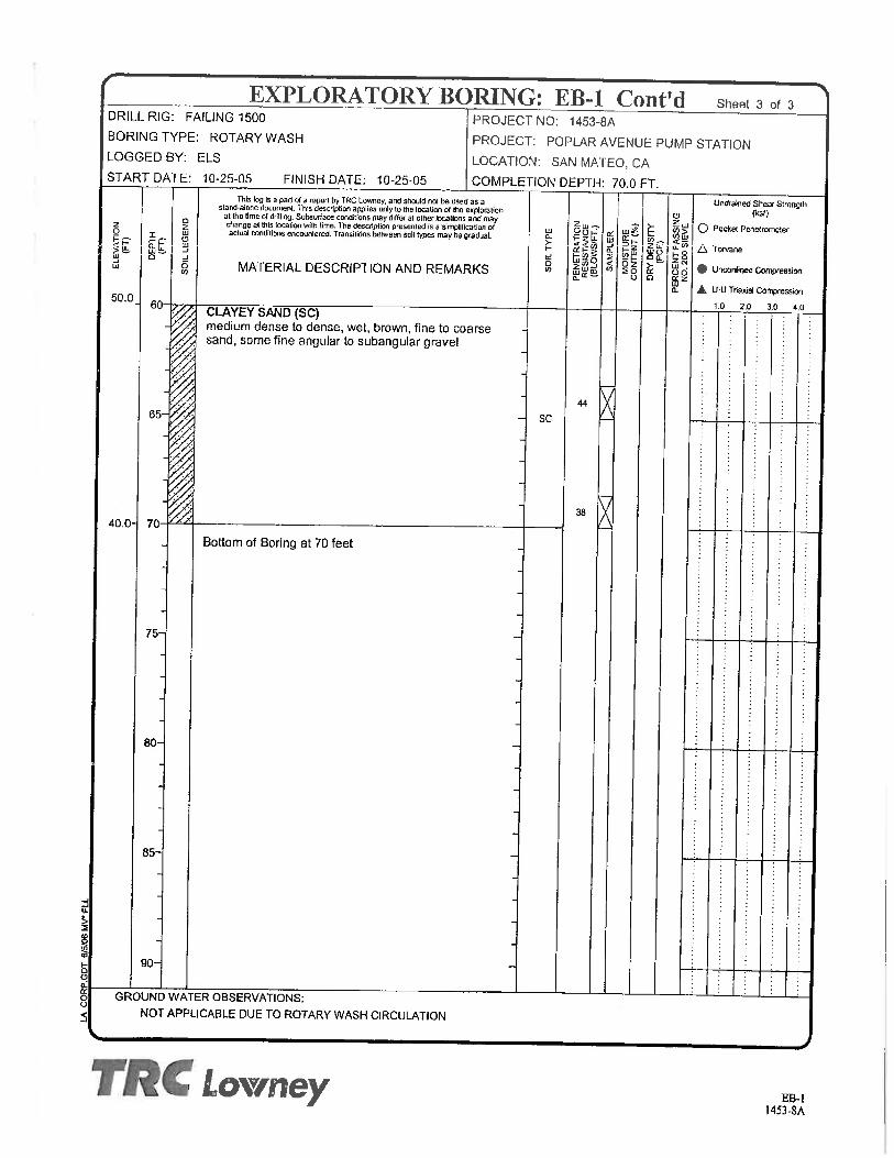
TRC Lowney’s field explorations consisted of drilling one mud-rotary boring to a depth of 70 feet below the existing grade (corresponding to Elevation 40 feet CSMD). Below the surface pavement, Boring EB-1 generally encountered undocumented fill underlain by young Bay Mud underlain by alluvial soil. The undocumented fill was encountered to a depth of 6 feet (Elevation 104 feet CSMD) below the existing grade and consisted of very stiff lean clay, medium dense clayey sand with gravel, and medium stiff lean clay with gravel. The undocumented fill was underlain by loose poorly graded gravel with clay and sand to a depth of 13 feet (Elevation 97 feet CSMD). About 20 feet of young Bay Mud was encountered below the fill to a depth of 33½ feet (Elevation 76.5 feet CSMD) below the existing grade and consisted of soft to medium stiff high plasticity clay with thin layers of medium dense poorly graded sand with clay. The young
Project No. 187-25-1 Page 3 November 9, 2016
Bay Mud was underlain by alluvial soil generally consisting of stiff high plasticity clay, very stiff sandy lean clay, and medium dense to dense clayey sand to a depth of 70 feet (Elevation 40 feet CSMD), the maximum depth explored. A Plasticity Index (PI) test was performed on a sample of the lean clay fill at a depth of 6 feet below the existing grade. The results of the test indicated the undocumented fill has a PI of 31 indicating high expansion potential. Ground water was not measured in EB-1 due to the use of drilling fluid. Ground water is anticipated to be at or near the elevation of the adjacent bay water (Elevation 99 feet CSMD) and subject to tidal fluctuations. Historic high ground water at the site is not mapped but is anticipated to be within 5 feet of the existing ground surface based on our experience in the project area. Geotechnical Concerns
From a geotechnical viewpoint, the project is feasible provided the concerns listed below are addressed in the project design. Soft, Highly Compressible Bay Mud Soil Profile Construction Through and Around the Levee High Ground and Surface Water Levels Soil Corrosion Potential Potential for Voids in the Levee Strong Ground Shaking
Recommendations for mitigation of the above geotechnical concerns are provided in the referenced geotechnical investigation report (Lowney, 2006) and some are updated as discussed in the sections below. Additionally, geotechnical concerns and recommendations for mitigation of shallow ground water and expansive soil are also discussed and provided in the referenced geotechnical report (Lowney, 2006). Earthwork
Grading is anticipated to include cuts of up to 25 feet below the existing grade for construction of the new wet well and fills of up to 5 feet for reconstruction of the existing levee and Bay Trail pathway. We understand that the existing wet well will be backfilled with light-weight cellular concrete. Earthwork recommendations for the proposed improvements are provided in the referenced geotechnical report (Lowney, 2006). Updated Recommendations
As discussed, the existing pump station is supported on timber piles. 12-inch square concrete piles were previously recommended for the new structures; however, 8-inch diameter micro-piles are now being considered. Supplemental recommendations for micro-pile foundations are provide in the following sections.
Project No. 187-25-1 Page 4 November 9, 2016
UPDATED SEISMIC DESIGN CRITERIA We understand that the project structural design will be based on the 2013 California Building Code (CBC), which provides criteria for the seismic design of buildings in Chapter 16. The “Seismic Coefficients” used to design buildings are established based on a series of tables and figures addressing different site factors, including the soil profile in the upper 100 feet below grade and mapped spectral acceleration parameters based on distance to the controlling seismic source/fault system. Based on the previously performed boring and our review of local geology, the site is underlain by more than 10 feet of Bay Mud that has an insitu moisture content greater than 40 percent. Therefore, we have classified the site as Soil Classification E. The mapped spectral acceleration parameters SS and S1 were calculated using the USGS computer program Earthquake Ground Motion Parameters, Version 5.1.0, revision date February 10, 2011, based on the site coordinates presented below and the site classification. The table below lists the various factors used to determine the seismic coefficients and other parameters. Table 1: CBC Site Categorization and Site Coefficients Classification/Coefficient Design Value Site Class E Site Latitude 37.583583° Site Longitude -122.315934° 0.2-second Period Mapped Spectral Acceleration1, SS 1.753g 1-second Period Mapped Spectral Acceleration1, S1 0.811g Short-Period Site Coefficient – Fa 0.9 Long-Period Site Coefficient – Fv 2.4 0.2-second Period, Maximum Considered Earthquake Spectral Response Acceleration Adjusted for Site Effects - SMS
1.577g
1-second Period, Maximum Considered Earthquake Spectral Response Acceleration Adjusted for Site Effects – SM1
1For Site Class B, 5 percent damped. MICRO-PILES Based on discussions with Biggs Cardoza Associates (BCA), the project structural engineers, we understand that micro-piles will be implemented to resist the loads from the new structures. Maximum design dead load plus live load will be on the order of 100 kips per pile are anticipated for the new structures, according to BCA. The depth, spacing and number of micro-piles depends on the strength of the soil, the geometry of the building foundation, and the required capacity. The design of the micro-piles should be performed in accordance with CBC Section 1810.3.10 including 1810.3.10.4, Seismic Requirements and PTI Recommendations for Prestressed Rock and Soil Anchors (PTI, 2004). For design and project budgeting purposes, the following criteria can be used for micro-pile design:
Project No. 187-25-1 Page 5 November 9, 2016
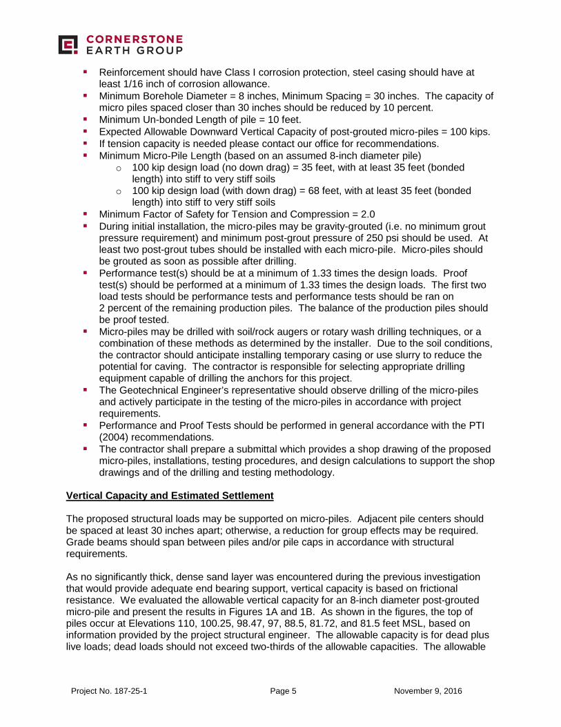
Reinforcement should have Class I corrosion protection, steel casing should have at least 1/16 inch of corrosion allowance.
Minimum Borehole Diameter = 8 inches, Minimum Spacing = 30 inches. The capacity of micro piles spaced closer than 30 inches should be reduced by 10 percent.
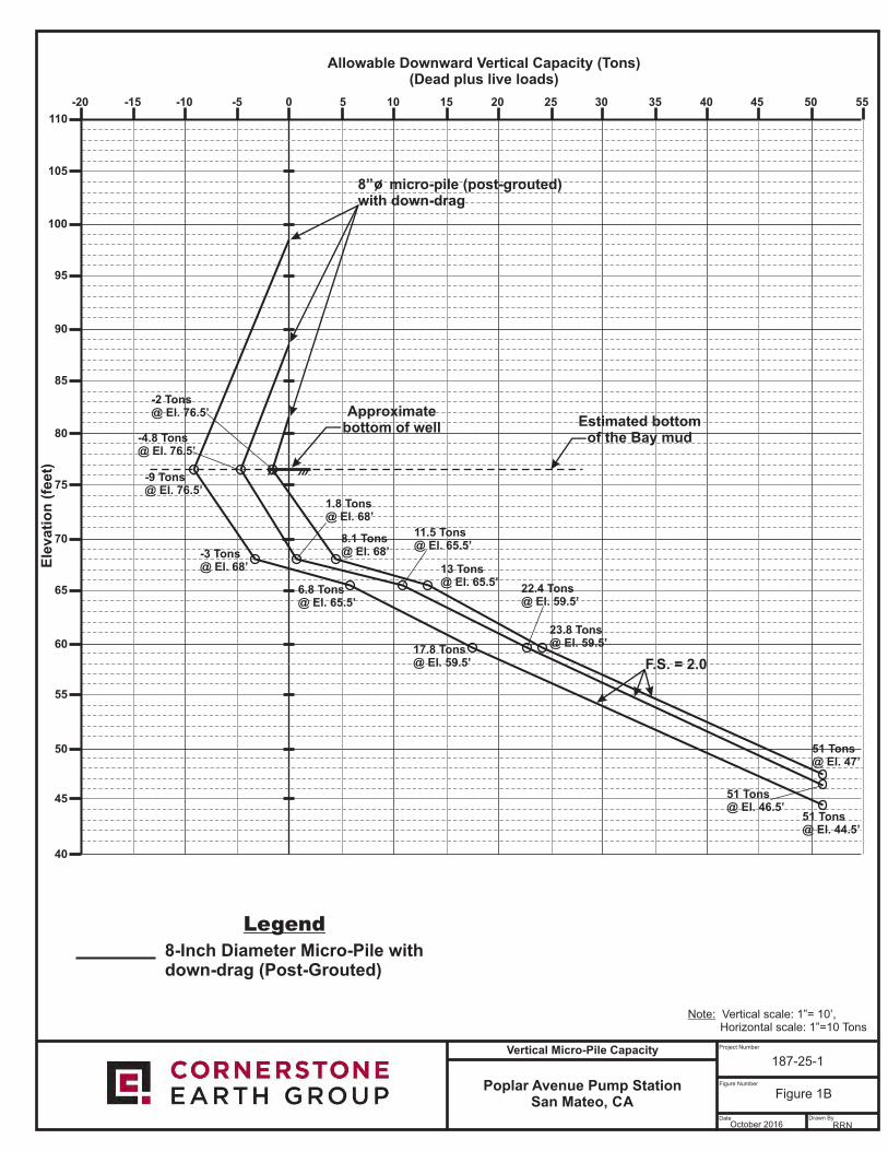
Minimum Un-bonded Length of pile = 10 feet. Expected Allowable Downward Vertical Capacity of post-grouted micro-piles = 100 kips. If tension capacity is needed please contact our office for recommendations. Minimum Micro-Pile Length (based on an assumed 8-inch diameter pile)
o 100 kip design load (no down drag) = 35 feet, with at least 35 feet (bonded length) into stiff to very stiff soils
o 100 kip design load (with down drag) = 68 feet, with at least 35 feet (bonded length) into stiff to very stiff soils
Minimum Factor of Safety for Tension and Compression = 2.0 During initial installation, the micro-piles may be gravity-grouted (i.e. no minimum grout
pressure requirement) and minimum post-grout pressure of 250 psi should be used. At least two post-grout tubes should be installed with each micro-pile. Micro-piles should be grouted as soon as possible after drilling.
Performance test(s) should be at a minimum of 1.33 times the design loads. Proof test(s) should be performed at a minimum of 1.33 times the design loads. The first two load tests should be performance tests and performance tests should be ran on 2 percent of the remaining production piles. The balance of the production piles should be proof tested.
Micro-piles may be drilled with soil/rock augers or rotary wash drilling techniques, or a combination of these methods as determined by the installer. Due to the soil conditions, the contractor should anticipate installing temporary casing or use slurry to reduce the potential for caving. The contractor is responsible for selecting appropriate drilling equipment capable of drilling the anchors for this project.
The Geotechnical Engineer’s representative should observe drilling of the micro-piles and actively participate in the testing of the micro-piles in accordance with project requirements.
Performance and Proof Tests should be performed in general accordance with the PTI (2004) recommendations.
The contractor shall prepare a submittal which provides a shop drawing of the proposed micro-piles, installations, testing procedures, and design calculations to support the shop drawings and of the drilling and testing methodology.
Vertical Capacity and Estimated Settlement The proposed structural loads may be supported on micro-piles. Adjacent pile centers should be spaced at least 30 inches apart; otherwise, a reduction for group effects may be required. Grade beams should span between piles and/or pile caps in accordance with structural requirements. As no significantly thick, dense sand layer was encountered during the previous investigation that would provide adequate end bearing support, vertical capacity is based on frictional resistance. We evaluated the allowable vertical capacity for an 8-inch diameter post-grouted micro-pile and present the results in Figures 1A and 1B. As shown in the figures, the top of piles occur at Elevations 110, 100.25, 98.47, 97, 88.5, 81.72, and 81.5 feet MSL, based on information provided by the project structural engineer. The allowable capacity is for dead plus live loads; dead loads should not exceed two-thirds of the allowable capacities. The allowable
Project No. 187-25-1 Page 6 November 9, 2016
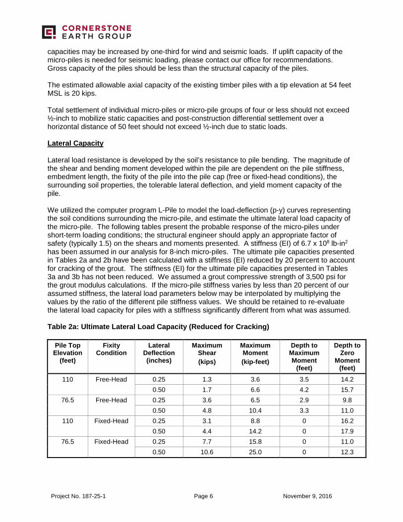
capacities may be increased by one-third for wind and seismic loads. If uplift capacity of the micro-piles is needed for seismic loading, please contact our office for recommendations. Gross capacity of the piles should be less than the structural capacity of the piles. The estimated allowable axial capacity of the existing timber piles with a tip elevation at 54 feet MSL is 20 kips. Total settlement of individual micro-piles or micro-pile groups of four or less should not exceed ½-inch to mobilize static capacities and post-construction differential settlement over a horizontal distance of 50 feet should not exceed ½-inch due to static loads. Lateral Capacity Lateral load resistance is developed by the soil’s resistance to pile bending. The magnitude of the shear and bending moment developed within the pile are dependent on the pile stiffness, embedment length, the fixity of the pile into the pile cap (free or fixed-head conditions), the surrounding soil properties, the tolerable lateral deflection, and yield moment capacity of the pile. We utilized the computer program L-Pile to model the load-deflection (p-y) curves representing the soil conditions surrounding the micro-pile, and estimate the ultimate lateral load capacity of the micro-pile. The following tables present the probable response of the micro-piles under short-term loading conditions; the structural engineer should apply an appropriate factor of safety (typically 1.5) on the shears and moments presented. A stiffness (EI) of 6.7 x 10⁸ lb-in2 has been assumed in our analysis for 8-inch micro-piles. The ultimate pile capacities presented in Tables 2a and 2b have been calculated with a stiffness (EI) reduced by 20 percent to account for cracking of the grout. The stiffness (EI) for the ultimate pile capacities presented in Tables 3a and 3b has not been reduced. We assumed a grout compressive strength of 3,500 psi for the grout modulus calculations. If the micro-pile stiffness varies by less than 20 percent of our assumed stiffness, the lateral load parameters below may be interpolated by multiplying the values by the ratio of the different pile stiffness values. We should be retained to re-evaluate the lateral load capacity for piles with a stiffness significantly different from what was assumed. Table 2a: Ultimate Lateral Load Capacity (Reduced for Cracking)
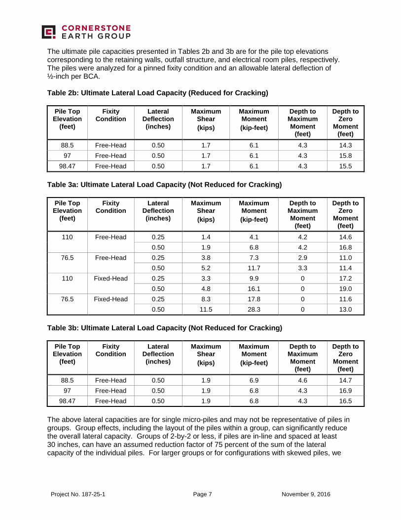
The ultimate pile capacities presented in Tables 2b and 3b are for the pile top elevations corresponding to the retaining walls, outfall structure, and electrical room piles, respectively. The piles were analyzed for a pinned fixity condition and an allowable lateral deflection of ½-inch per BCA. Table 2b: Ultimate Lateral Load Capacity (Reduced for Cracking)
98.47 Free-Head 0.50 1.9 6.8 4.3 16.5 The above lateral capacities are for single micro-piles and may not be representative of piles in groups. Group effects, including the layout of the piles within a group, can significantly reduce the overall lateral capacity. Groups of 2-by-2 or less, if piles are in-line and spaced at least 30 inches, can have an assumed reduction factor of 75 percent of the sum of the lateral capacity of the individual piles. For larger groups or for configurations with skewed piles, we
Project No. 187-25-1 Page 8 November 9, 2016
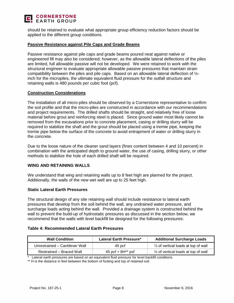
should be retained to evaluate what appropriate group efficiency reduction factors should be applied to the different group conditions. Passive Resistance against Pile Caps and Grade Beams Passive resistance against pile caps and grade beams poured neat against native or engineered fill may also be considered; however, as the allowable lateral deflections of the piles are limited, full allowable passive will not be developed. We were retained to work with the structural engineer to evaluate appropriate allowable passive pressures that maintain strain compatibility between the piles and pile caps. Based on an allowable lateral deflection of ½-inch for the micropiles, the ultimate equivalent fluid pressure for the outfall structure and retaining walls is 480 pounds per cubic foot (pcf). Construction Considerations The installation of all micro-piles should be observed by a Cornerstone representative to confirm the soil profile and that the micro-piles are constructed in accordance with our recommendations and project requirements. The drilled shafts should be straight, and relatively free of loose material before grout and reinforcing steel is placed. Since ground water most likely cannot be removed from the excavations prior to concrete placement, casing or drilling slurry will be required to stabilize the shaft and the grout should be placed using a tremie pipe, keeping the tremie pipe below the surface of the concrete to avoid entrapment of water or drilling slurry in the concrete. Due to the loose nature of the cleaner sand layers (fines content between 4 and 10 percent) in combination with the anticipated depth to ground water, the use of casing, drilling slurry, or other methods to stabilize the hole of each drilled shaft will be required. WING AND RETAINING WALLS We understand that wing and retaining walls up to 8 feet high are planned for the project. Additionally, the walls of the new wet well are up to 25 feet high. Static Lateral Earth Pressures The structural design of any site retaining wall should include resistance to lateral earth pressures that develop from the soil behind the wall, any undrained water pressure, and surcharge loads acting behind the wall. Provided a drainage system is constructed behind the wall to prevent the build-up of hydrostatic pressures as discussed in the section below, we recommend that the walls with level backfill be designed for the following pressures: Table 4: Recommended Lateral Earth Pressures
Wall Condition Lateral Earth Pressure* Additional Surcharge Loads Unrestrained – Cantilever Wall 45 pcf ⅓ of vertical loads at top of wall
Restrained – Braced Wall 45 pcf + 8H** psf ½ of vertical loads at top of wall * Lateral earth pressures are based on an equivalent fluid pressure for level backfill conditions ** H is the distance in feet between the bottom of footing and top of retained soil
Project No. 187-25-1 Page 9 November 9, 2016
Wet well walls should be designed as restrained walls. Since adequate drainage likely cannot be provided behind the full height of the walls, an additional equivalent fluid pressure of 40 pcf should be added to the values above for both restrained and unrestrained walls for the portion of the wall that will not have drainage. Waterproofing of the walls may be considered where moisture penetration and/or efflorescence are not desired. Seismic Lateral Earth Pressures The 2013 CBC states that lateral pressures from earthquakes should be considered in the design of basements and retaining walls retaining more than 6 feet of backfill height. We reviewed the seismic earth pressures for the proposed basement using procedures generally based on the Mononobe-Okabe method. Because the walls of the new wet well are greater than 10 to 12 feet in height, and peak ground accelerations are greater than 0.40g, we checked the result of the seismic increment when added to the recommended active earth pressure against the recommended fixed wall earth pressures. Because the wall is restrained, or will act as a restrained wall, and will be designed for 85 pcf (equivalent fluid pressure) plus a uniform earth pressure of 8H psf, based on current recommendations for seismic earth pressures (Lew et al., SEAOC 2010), it appears that active earth pressures plus a seismic increment do not exceed the fixed wall earth pressures. Therefore, an additional seismic increment above the design earth pressures is not required as long as the walls are designed for the restrained wall earth pressures and undrained backfill conditions recommended above. If the design pressure is different, we should be contacted to review our recommendations. The seismic increment discussed above is not required for site retaining walls less than 6 feet in height. Vehicle Surcharge Loads We understand that the wing walls and wet well will be subject to traffic loads of equivalent to Caltrans HS20-44 Loading. We recommend that the wing walls and the walls of the new wet well be designed to resist a surcharge load of 250 psf located at the top of the wall. Wall Drainage Adequate drainage should be provided by a subdrain system behind all walls where feasible. This system should consist of a 4-inch minimum diameter perforated pipe placed near the base of the wall (perforations placed downward). The pipe should be bedded and backfilled with Class 2 Permeable Material per Caltrans Standard Specifications, latest edition. The permeable backfill should extend at least 12 inches out from the wall and to within 2 feet of outside finished grade. Alternatively, ½-inch to ¾-inch crushed rock may be used in place of the Class 2 Permeable Material provided the crushed rock and pipe are enclosed in filter fabric, such as Mirafi 140N or approved equivalent. The upper 2 feet of wall backfill should consist of compacted on-site soil. The subdrain outlet should be connected to a free-draining outlet or sump. Miradrain, Geotech Drainage Panels, or equivalent drainage matting can be used for wall drainage as an alternative to the Class 2 Permeable Material or drain rock backfill. Horizontal strip drains connecting to the vertical drainage matting may be used in lieu of the perforated pipe and crushed rock section. The vertical drainage panel should be connected to the perforated pipe or horizontal drainage strip at the base of the wall, or to some other closed or through-wall system such as the TotalDrain system from AmerDrain. Sections of horizontal
Project No. 187-25-1 Page 10 November 9, 2016
drainage strips should be connected with either the manufacturer’s connector pieces or by pulling back the filter fabric, overlapping the panel dimples, and replacing the filter fabric over the connection. At corners, a corner guard, corner connection insert, or a section of crushed rock covered with filter fabric must be used to maintain the drainage path. Drainage panels should terminate 18 to 24 inches from final exterior grade. The Miradrain panel filter fabric should be extended over the top of and behind the panel to protect it from intrusion of the adjacent soil. Backfill Where surface improvements will be located over the retaining wall backfill, backfill placed behind the walls should be compacted to at least 95 percent relative compaction in the upper 5 feet using light compaction equipment. Where no surface improvements are planned, backfill should be compacted to at least 90 percent. If heavy compaction equipment is used, the walls should be temporarily braced. Based on the current plans, we understand that drainage swales are planned behind the retaining walls, which we highly recommend. As discussed previously, consideration should be given to the transitions from on-grade to on-structure. Providing subslabs or other methods for reducing differential movement of flatwork or pavements across this transition should be included in the project design. Foundations Retaining walls may be supported on micro-piles designed in accordance with the recommendations presented in this supplemental letter. Plans, Specifications, and Construction Review
Because subsurface conditions may vary considerably and in order to check that our recommendations have been properly implemented, we recommend that our firm be retained to 1) review the final construction plans and specifications and 2) observe the earthwork and foundation installation. Also, the assumed and/or actual geotechnical conditions can be greatly affected by the construction process. For the above reasons, our geotechnical recommendations are contingent upon our firm providing geotechnical observation and testing services during construction. Closure
We hope this provides the information that you need at this time. The recommendations presented in this letter have been prepared for the sole use of Schaaf & Wheeler specifically for the subject project at East Poplar Avenue in San Mateo, California. The opinions, conclusions, and recommendations presented in this letter have been formulated in accordance with accepted geotechnical engineering practices that exist in Northern California at the time this report was prepared. No warranty, expressed or implied, is made or should be inferred. Recommendations in this letter and previous geotechnical report are based upon the soil and ground water conditions encountered during our subsurface exploration. If variations or
Project No. 187-25-1 Page 11 November 9, 2016
unsuitable conditions are encountered during construction, Cornerstone must be contacted to provide supplemental recommendations, as needed.
Schaaf and Wheeler may have provided Cornerstone with plans, reports and other documents prepared by others. Schaaf and Wheeler understands that Cornerstone reviewed and relied on the information presented in these documents and cannot be responsible for their accuracy.
Cornerstone prepared this letter with the understanding that it is the responsibility of the owner or his representatives to see that the recommendations contained in this letter are presented to other members of the design team and incorporated into the project plans and specifications, and that appropriate actions are taken to implement the geotechnical recommendations during construction.
Conclusions and recommendations presented in this letter are valid as of the present time for the development as currently planned. Changes in the condition of the property or adjacent properties may occur with the passage of time, whether by natural processes or the acts of other persons. In addition, changes in applicable or appropriate standards may occur through legislation or the broadening of knowledge. Therefore, the conclusions and recommendations presented in this letter may be invalidated, wholly or in part, by changes beyond Cornerstone’s control. This letter should be reviewed by Cornerstone after a period of three (3) years has elapsed from the date of this report. In addition, if the current project design is changed, then Cornerstone must review the proposed changes and provide supplemental recommendations, as needed.
An electronic transmission of this letter may also have been issued. While Cornerstone has taken precautions to produce a complete and secure electronic transmission, please check the electronic transmission against the hard copy version for conformity.
Recommendations provided in this letter are based on the assumption that Cornerstone will be retained to provide observation and testing services during construction to confirm that conditions are similar to that assumed for design, and to form an opinion as to whether the work has been performed in accordance with the project plans and specifications. If we are not retained for these services, Cornerstone cannot assume any responsibility for any potential claims that may arise during or after construction as a result of misuse or misinterpretation of Cornerstone’s letter by others. Furthermore, Cornerstone will cease to be the Geotechnical-Engineer-of-Record if we are not retained for these services.