834320 00 91 13 - 1 ADDENDUM SECTION 00 91 13 ADDENDUM Addendum No. 01 Owner: Village of Deckerville Contract: 300,000 Gallon Elevated Water Storage Tower Project: 300,000 Gallon Elevated Water Storage Tower Date: Owner’s Contract No.: Engineer’s Project No.: 834320 ENGINEER: Fleis & VandenBrink Engineering, Inc. NOTICE TO ALL PROSPECTIVE BIDDERS BIDS DUE: Tuesday, July 17, 2018 at 3:00 P.M.-- ISSUED TO ALL PLANHOLDERS OF RECORD ===================================================================================== This Addendum is a part of the Contract Documents and modifies the previously issued Bidding Documents. Acknowledge receipt of this Addendum in the space provided on the Bid Form. Failure to do so may result in rejection of the Bid. SPECIFICATION CHANGES ITEM NO. 1: Section 00 11 13 – ADVERTISEMENT FOR BIDS Change the time that bids will be received from 2:00 P.M. to 3:00 P.M. ITEM NO. 2: Section Appendix A – Geotechnical Report Add the attached report into Appendix A ATTACHMENTS: Geotechnical Exploration and Engineering Report dated July 03, 2018. CLARIFICATIONS: The timing for the removal of the existing 40,000 gallon elevated water tank in not dependent on the completion of the new water tank. It can be removed at any time during the project. END OF SECTION
Transcript
834320 00 91 13 - 1 ADDENDUM
SECTION 00 91 13
ADDENDUM
Addendum No. 01
Owner: Village of Deckerville
Contract: 300,000 Gallon Elevated Water Storage Tower
Project: 300,000 Gallon Elevated Water Storage Tower Date:
This Addendum is a part of the Contract Documents and modifies the previously issued Bidding Documents. Acknowledge receipt of this Addendum in the space provided on the Bid Form. Failure to do so may result in rejection of the Bid.
SPECIFICATION CHANGES
ITEM NO. 1:
Section 00 11 13 – ADVERTISEMENT FOR BIDS
Change the time that bids will be received from 2:00 P.M. to 3:00 P.M.
ITEM NO. 2:
Section Appendix A – Geotechnical Report
Add the attached report into Appendix A
ATTACHMENTS:
Geotechnical Exploration and Engineering Report dated July 03, 2018.
CLARIFICATIONS:
The timing for the removal of the existing 40,000 gallon elevated water tank in not dependent on the completion of the new water tank. It can be removed at any time during the project.
END OF SECTION
GEOTECHNICAL EXPLORATION AND ENGINEERING REPORT
FOR THE:
PROPOSED SLEEP DECKERVILLE WATER TANK DECKERVILLE VILLAGE, SANILAC COUNTY, MICHIGAN
Luay Al-Durzi, Geotechnical Engineer
PREPARED FOR:
FLEIS & VANDENBRINK 2125 RIDGEWOOD DRIVE, SUITE # 101
MIDLAND, MICHIGAN 48642
Musana Nabil, Department Manager
PREPARED BY:
PROFESSIONAL SERVICE INDUSTRIES, INC. 3120 SOVEREIGN DRIVE, SUITE C
LANSING, MICHIGAN 48911
Randal Pail, P.E. Principal Consultant
Director
JULY 03, 2018
PSI PROJECT NO. 0406-193
TABLE OF CONTENTS
PROJECT INFORMATION ........................................................................................................ 1
PROJECT AUTHORIZATION .............................................................................................................................. 1 PROJECT DESCRIPTION ................................................................................................................................... 1 PURPOSE AND SCOPE OF SERVICES ................................................................................................................... 2
SITE AND SUBSURFACE CONDITIONS ....................................................................................... 2
SITE LOCATION AND DESCRIPTION .................................................................................................................... 2 FIELD EXPLORATION AND LABORATORY TESTING ................................................................................................ 3 SUBSURFACE/SURFACE CONDITIONS ................................................................................................................ 3 GROUNDWATER INFORMATION ....................................................................................................................... 5 SITE SEISMIC CLASSIFICATION .......................................................................................................................... 5
EVALUATION AND RECOMMENDATIONS ............................................................................... 6
SITE PREPARATION AND EARTHWORK ............................................................................................................... 6 FOUNDATION RECOMMENDATIONS FOR SHALLOW FOUNDATIONS ........................................................................ 8 LATERAL EARTH PRESSURE RECOMMENDATIONS ................................................................................................ 9
CONSTRUCTION CONSIDERATIONS ...................................................................................... 10
APPENDIX Figure 1 – Site Location Diagram Figure 2 – Boring Location Diagram Boring Logs – (SB-01 to SB-03) Lab Tests Results Soil Classification Chart PSI General Notes ASFE – Important Information About Your Geotechnical Engineering Report
Project Number: 0406193 Proposed Deckerville Water Tank
July 03, 2018 Page 1
www.intertek.com/building
PROJECT INFORMATION Project Authorization This engineering report presents the results of our geotechnical engineering exploration performed relative to the proposed Deckerville Water Tank in Deckerville Village, Sanilac County, Michigan. This exploration was performed for Fleis & VandenBrink in accordance with the PSI Proposal No. GEO120180406 dated April 26, 2018. The proposal included a proposed scope of services, estimated cost, unit rates, and time schedule. Authorization to perform this exploration and analysis was in the form of an acceptance of PSI’s proposal by Mr. Douglas R. Stevens, Project Engineer of Fleis & VandenBrink. Project Description Project information was provided by Mr. Douglas R. Stevens, Project Engineer of Fleis & VandenBrink via email. The information provided to PSI includes:
• Project Description and Scope of the Project. • Project Site Plan showing the boring locations and reference topography elevations. • Structural details and load calculations for a similar tank prepared by Caldwell Tanks, Inc.
Briefly, PSI understands that it is planned to construct a new water tank in Deckerville Village, Sanilac County, Michigan. The water tank will be a 300,000-gallon, elevated water tank approximately 156 feet in height. The tank will be located approximately 450 feet east of the intersection of Ruth Road and Stoutenburg Street. The proposed elevated water tank will be a spherical type tank with a single pedestal base. Based on the information provided, the diameter of the tank pedestal base will be approximately 26 feet bearing at depth of approximately 10 feet below the ground surface. The proposed tank will be of welded steel plate construction. PSI also understands that the total weight of the tank including the water will not exceed 2750 Kips. Based on the topography elevations provided by Fleis & VandenBrink, the site base elevation will approximately 819 feet. Current grades in the area of the water tank base are on the order of 817 feet. The geotechnical recommendations presented in this report are based on the available project information and results of our geotechnical exploration. If any of the noted information is considered incorrect or is changed, please inform PSI in writing so that we may amend the recommendations presented in this report if appropriate and if desired by the client. PSI will not be responsible for the implementation of its recommendations when it is not notified of changes in the project. PSI should be consulted once the structure design has been finalized. Additional subsurface investigation may need to be performed by PSI at that time.
Project Number: 0406193 Proposed Deckerville Water Tank
July 03, 2018 Page 2
www.intertek.com/building
Purpose and Scope of Services The purpose of this exploration was to evaluate the subsurface conditions at the site and to develop geotechnical design criteria for support of foundations for the planned project. The scope of the exploration and analysis included a reconnaissance of the project site, completion of three (3) soil borings. The proposed scope of service also included field and laboratory testing of recovered samples, and an engineering analysis and evaluation of the subsurface materials encountered. The scope of services did not include an environmental assessment for determining the presence or absence of wetlands, hazardous or toxic materials in the soil, bedrock, surface water, groundwater, or air on, below or around this site. Any statement in this report or on the boring logs regarding odors, colors, and unusual or suspicious items or conditions are strictly for the information of the Fleis & VandenBrink. Prior to the development of any site, an environmental assessment is advisable. As directed by the scope of work provided by Fleis & VandenBrink. PSI did not provide any service to investigate or detect the presence of moisture, mold or other biological contaminates in or around any structure, or any service that was designed or intended to prevent or lower the risk of the occurrence of the amplification of the same. Fleis & VandenBrink acknowledges that mold is ubiquitous to the environment with mold amplification occurring when building materials are impacted by moisture. Fleis & VandenBrink further acknowledges that site conditions are outside of PSI’s control, and that mold amplification will likely occur, or continue to occur, in the presence of moisture. As such, PSI cannot and shall not be held responsible for the occurrence or recurrence of mold amplification. PSI also provides an array of complementary environmental and industrial hygiene services to assist our clients in successfully assessing and developing properties such as the one referenced in this report. PSI’s environmental consultants apply their experience, local geologic knowledge and thorough understanding of ASTM standards, environmental risk, and regulatory knowledge to conduct due diligence assessments of a wide range or property types and proposed developments.
SITE AND SUBSURFACE CONDITIONS Site Location and Description The project site is located on the east side of Ruth Road, east of its intersection with Stoutenburg Street in Deckerville Village, Sanilac County, Michigan. The Site is relatively level in the building pad area with elevations ranging from approximately 817 feet to 819 feet. The site is a vacant lot covered with grass. Surrounding properties consist of residential, agriculture and retail developments. The general site location is shown on the site location diagram in the Appendix as Figure No. 1.
Project Number: 0406193 Proposed Deckerville Water Tank
July 03, 2018 Page 3
www.intertek.com/building
Field Exploration and Laboratory Testing The site subsurface conditions were determined by completion of three (3) soil borings: Soil borings SB-01 through SB-03. Soil borings advanced to depths of approximately (50) feet below the existing ground surface. The soil boring locations and depths were established by Fleis & VandenBrink and located in the field by PSI. The approximate boring positions are depicted on the Boring Location Diagram included in the Appendix. The soil borings were performed between May 29 and June 11, 2018 by means of a CME 55 truck-mounted drilling rig equipped with a rotary head utilizing 3¼ inch hollow-stem augers to advance the boreholes. Representative soil samples were recovered employing split-barrel sampling procedures in general accordance with "Penetration Test and Split-Barrel Sampling of Soils" (ASTM D1586). After completion of the test borings, the holes were backfilled with the excavated soils and pavement surfaces were patched where applicable. Determination of the ground surface elevations by survey at the test boring positions was not within the scope of PSI’s services. Approximate ground elevations were obtained using Google Earth Pro and topographic map provided to PSI. Prior to final design and construction, field measurement at the boring locations should be made by a professional land surveyor registered in the State of Michigan. References to depths in this report and on the attached boring logs are from the existing ground surface unless otherwise noted. In addition to the field exploration, a laboratory-testing program was conducted to evaluate engineering characteristics of the subsurface materials. The laboratory-testing program included visual classification and moisture content tests on all the material recovered. The unconfined compression strength of the cohesive soils encountered was estimated utilizing a calibrated hand penetrometer. The results of these tests are located on the boring logs which are included in the Appendix. Each phase of the laboratory testing program was conducted in general accordance with applicable ASTM specifications. The unused portion of the soil samples will be placed in storage at PSI’s Lansing, Michigan facility. Unless otherwise requested in writing, the samples will be discarded after 60 days from the submission of the final report. Subsurface/Surface Conditions The surface and subsurface conditions encountered at the project site at the time of our field exploration are summarized in the table below:
Table 1: Existing Surface/Subsurface Summary
Soil Boring
Depth (feet)
Approximate Elevation
(feet)
Surficial Materials and Thickness Major Native Soils
SB-01 50 818 12 inches of Topsoil
Brown & Gray Sandy Clay, Gray Silty Clay
Project Number: 0406193 Proposed Deckerville Water Tank
July 03, 2018 Page 4
www.intertek.com/building
At the time of our field exploration the ground surface, at soil boring locations SB-01 through SB-03, was covered by approximately 10 to 12 inches of topsoil. Below the topsoil, layers of native soils were encountered through the maximum exploration depth of fifty (50) feet below the existing ground surface as described below: Stratum 1: Brown to Gray Sandy Clay: A stratum of brown to gray sandy clay with variable percentages of silt and gravel was encountered at all boring locations. The brown to gray sandy clay extended to depths ranging between approximately 13½ to 18½ feet below the ground surface. The corrected Standard Penetration Test values (N60 values) within the brown to gray sandy clay strata ranged from approximately 18 to 29 blows per foot and the unconfined compressive strength of the brown to gray sandy clay stratum ranged from approximately 2¾ to more than 4½ tons per square foot, indicating very stiff to hard consistencies. The moisture contents of the tested soil samples from this stratum ranged from approximately 12 to 14 percent. The recovered soil samples visually appeared to be in a moist to very moist condition when examined in the laboratory. Stratum 2: Gray Silty Clay: A stratum gray silty clay with variable percentages of sand and gravel was encountered at all boring locations below the brown to gray sandy clay. The gray silty clay extended to the final explored depth of approximately 50 feet below the ground surface. The corrected Standard Penetration Test values (N60 values) within the gray silty clay strata ranged from approximately 8 to 22 blows per foot and the unconfined compressive strength of the gray silty clay stratum ranged from approximately ½ to 3 tons per square foot, indicating soft to very stiff consistencies. The moisture contents of the tested soil samples from this stratum ranged from approximately 13 to 17 percent. The recovered soil samples visually appeared to be in a moist to very moist condition when examined in the laboratory. Cobbles and/or boulders were not encountered during drilling operations the boring locations. The boring logs should be referenced with respect to this information. The presence of boulders and cobbles in the profile is a result of the geologic method of deposition of the soil materials at this site. Even where cobbles or boulders were not noted within the profile they could be encountered very nearby or between the boring positions. The contractor should be equipped for this condition. The above subsurface descriptions are of a generalized nature and are provided to highlight the major soil strata encountered. The Boring Logs included in the Appendix should be reviewed for specific information as to individual boring locations. The stratification shown on the Boring Logs represents the conditions encountered at the specific boring locations. Variations may occur and should be expected between
Surficial Materials and Thickness Major Native Soils
SB-02 50 818 12 inches of Topsoil
Brown & Gray Sandy Clay, Gray Silty Clay
SB-03 50 819 10 inches of Topsoil
Brown & Gray Sandy Clay, Gray Silty Clay
Project Number: 0406193 Proposed Deckerville Water Tank
July 03, 2018 Page 5
www.intertek.com/building
boring locations. The stratification represents the approximate boundary between subsurface materials; however, the actual transition may be gradual, abrupt, or not clearly defined. In the absence of foreign substances or debris, it is often difficult to distinguish between native soils and clean fill soil. Groundwater Information Free groundwater was not encountered during drilling operations or upon completion. Collapse of the soils above groundwater levels (i.e. “dry cave”) was not observed during drilling operations. The Boring Logs included in the Appendix should be reviewed for specific information as to depths of groundwater and cave in. It is possible for a groundwater table to vary within the depths explored during other times of the year depending upon climatic conditions (seasonal fluctuation). Groundwater monitoring wells are required to accurately define the position and fluctuation of the groundwater table, especially if a boring is drilled in cohesive soil, where several days or weeks may be required for the groundwater to reach a static level. The installation of such monitoring wells was not included in the scope of services for this project. The change in color of the soil from brown to gray may indicate the long-term minimum piezometric level in the area. Based on the color change from brown to gray at the borings performed, the long term piezometric level at this site may be located at a depth ranging between approximately 8.5 to 13.5 feet below the existing ground surface. Site Seismic Classification Sanilac County in Michigan lies in the Central Stable Tectonic Region and in Seismic Zone area 0 of probable seismic activity of the International Building Code (IBC). This zone indicates that minor damages due to occasional earthquakes might be expected in this area. In the 2012 Michigan Building Code (MBC), the State of Michigan has adopted the provisions of the International Building Code (IBC). The Site Class is based on a weighted average of known or estimated soil properties for the uppermost 100 feet of the subsurface profile. Soil borings at the project site extended to a maximum depth of approximately 50 feet below the existing ground surface. Based on the regional geologic mapping as well as data available on the Water Well Record Retrieval System of the Department of Environmental Quality in the State of Michigan, PSI anticipates that the subsurface conditions below the explored depth may consist predominantly from end moraines of fine-textured glacial till deposits. Bedrock in Deckerville is most likely part of the Coldwater Shale. The bedrock is often encountered at depths more than 100 feet. Based on our review of the available data, knowledge of regional geology, the Standard Penetration Test (SPT) N-values and approximated soil shear strength, PSI estimates that the seismic design for this project, based on the upper 100 feet of the subsurface soil and rock profile, would be Site Class D. The 2012 International Building Code requires a site class for the calculation of earthquake design forces. This class is a function of soil type (i.e., depth of soil and strata types). Based on the depth to rock and the estimated shear strength of the soil at the boring locations, Site Class “D” is recommended.
Project Number: 0406193 Proposed Deckerville Water Tank
July 03, 2018 Page 6
www.intertek.com/building
The 2012/2015 IBC probabilistic ground motion values near 43.532360° N and -82.733008° W are as follows:
The Site Coefficients, Fa and Fv were interpolated from 2012 IBC Tables 1613.3(1) and 1613.3(2) as a function of the site classification and the mapped spectral response acceleration at the short (Ss) and 1 second (S1) periods. The development of shear strains tending to cause liquefaction of sand deposits is governed by the character of the ground motion (i.e. acceleration and frequency), soil type, groundwater level, and in-situ stress conditions. PSI believes the risk of liquefaction occurring at this site is low based on the site being in a low seismic activity area.
EVALUATION AND RECOMMENDATIONS Site Preparation and Earthwork Prior to site grading activities or excavation for foundation elements, existing underground utilities, and structures, should be identified and rerouted or properly abandoned in-place. Existing underground utilities that are not re-routed or abandoned should be adequately marked and protected to minimize the potential for damage during construction activities. Existing topsoil, as well as any old fill soils or apparent old fill soils, should be stripped from the planned construction areas. Topsoil, as well as undocumented fill, and soils containing organics can potentially undergo high and variable volume changes when subjected to loads, resulting in detrimental performance of floor slabs, structural fills and shallow foundations placed on them. Apparent old fill was not encountered at the boring locations. However, it may be encountered within the proposed tank area between the performed boring locations. After the surface structures, vegetation, and topsoil have been removed from the areas of construction and any cut sections are performed, exposed subgrades should be observed and thoroughly proof rolled/compacted with a large, heavy rubber-tired vehicle prior to the placement of engineered fill or backfill required to achieve the proposed subgrade elevation. Areas that exhibit instability or are observed to rut or deflect excessively under the moving load should be further undercut, stabilized by aeration, drying (if wet) and additional compaction to attain a stable finished subgrade. The proof rolling/compacting and undercutting activities should be performed during a period of dry weather and should be performed under the supervision of the geotechnical engineer’s representative.
Project Number: 0406193 Proposed Deckerville Water Tank
July 03, 2018 Page 7
www.intertek.com/building
Where subgrade conditions are not improved through aeration, drying and compaction, or where undercut and replacement is considered impractical due to the underlying soil and groundwater conditions, it may be necessary to stabilize localized areas of subgrade instability with a woven geotextile, geogrid and a layer of well graded crushed concrete or well graded coarse aggregate such as MDOT 4AA or 6A or 21AA dense-graded aggregate. The need for the use of geotextile and the thickness and gradation requirements of the crushed aggregate layer required should be determined at the time of the subgrade preparation, based on the condition of the exposed subgrade at the time of construction. The subgrade should be stabilized prior to placement of engineered fill or aggregate base course. Engineered fill or backfill required to achieve the proposed subgrade elevation should be placed and properly compacted as outlined below under the full-time observation of PSI. New fill supporting at-grade structures should be an environmentally clean material, free of organic matter, frozen soil, or other deleterious material. The material proposed to be used as engineered fill should be evaluated and approved for use by a PSI geotechnical engineer or his representative prior to placement in the field. Fill materials should be placed in maximum horizontal lifts of 8 inches of loose material and should be compacted within the range of ±2% of the optimum moisture content value. Moisture contents should be adjusted to the proper levels prior to placement and compaction. Adequate compaction will not be achieved if the fill is in a saturated condition. Wet soils may require drying or mixing with dry soil to facilitate compaction. If water must be added to dry soil, it should be uniformly applied and thoroughly mixed into the soil by disking or scarifying prior to compaction. The structural fill should be compacted to 95% of the Modified Proctor maximum dry density as determined by ASTM D1557. Each lift of engineered fill should be tested for conformance to the project density requirements by a representative of PSI prior to placement of subsequent lifts. A minimum of one test should be performed for each lift, unless otherwise specified by the engineer. The moisture/density relationship (proctor) of the material to be used as engineered fill should be evaluated by a PSI geotechnical engineer or his representative prior to placement in the field. PSI recommends one proctor test for every 5,000 cubic yards (cyds) of fill and one test per each change in fill material. PSI recommends that imported granular soils conform to the gradation requirements of MDOT Class II granular material. In addition, free-draining, non-plastic granular material such as MDOT Class II granular material is recommended for use as backfill against foundations and below grade walls. PSI recommends that imported cohesive soils used as engineered fill below at-grade structural elements have a liquid limit less than 40 percent and a plasticity index in the range of 10 to 25. A sheep’s foot roller is recommended for compaction if cohesive soils are used. Vibratory compaction equipment should be used for compaction in granular soils. Small, hand-operated compaction equipment should be used in confined spaces and against below-grade walls and foundations. Organic soils, old fill and other deleterious materials, which are removed or uncovered during site grading and subgrade undercut operations, foundation and utility excavations at this site, must be wasted in non-load bearing areas such as landscaped areas or removed from the site as directed by the project’s engineer and should not be reused as engineered fill in other areas of the site.
Project Number: 0406193 Proposed Deckerville Water Tank
July 03, 2018 Page 8
www.intertek.com/building
Construction traffic should be restricted from the exposed subgrade to help reduce the potential for loosening of the subgrade soils, particularly where excess moisture is present from groundwater and/or precipitation. PSI recommends that the fill be strategically placed so that the construction equipment remains on newly placed fill soils and not on the exposed subgrade during fill placement. Foundation Recommendations for Shallow Foundations It is anticipated that the bottom of the circular, continuous footing will be located at 10 feet below the existing grade, to provide adequate frost protection and to help in resisting the overturning moments. At this depth and these minimum footing dimensions, shallow ring wall type foundations supported on the native soils can be designed for a maximum net allowable soil bearing pressure of 3,000 psf, based on dead load plus design live load. This net allowable bearing pressure can be increased by one-third to accommodate transient loads (such as earthquakes or wind loads). The net pressure is the pressure in excess of the minimum surrounding overburden pressure at the footing base elevation. PSI has not analyzed the soil conditions relative to overturning moments. Foundations bearing on new engineered fill placed over suitable native soils can also be designed for a maximum net allowable soil bearing pressure of 3,000 psf. Based on the known subsurface conditions and site geology, laboratory testing and past local experience, we anticipate that properly designed and constructed footings supported on the recommended, observed and approved native soils, or properly compacted structural fill should experience maximum long-term settlement within the silty clay soils to be on the order of 3 inches or less and a total and differential settlement on the order of 1½ inches. The total long-term settlement within the silty clay soils to be on the order of 3½ inches. It should be noted that the settlement is calculated based on the total vertical load for the proposed tank and does not includes the moment load applied at the tank base. System connections should be designed to accommodate anticipated settlements and movement from seismic activity. The footing excavations should be observed by a representative of PSI prior to steel or concrete placement to assess that the foundation materials are capable of supporting the design loads and are consistent with the materials discussed in this report. If soft, wet, loose or unsuitable soil zones are encountered at the bottom of footing excavations, the soil material in those zones should be removed and replaced with compacted, engineered granular backfill. If an over excavation and backfill procedure is utilized, it will require widening the deepened excavation in all directions at least 1 foot beyond the edges of the footing for each 1 foot of over excavation depth. The over excavation should then be backfilled in maximum 8 inch thick loose lifts with suitable granular fill material compacted to at least 95 percent of the maximum modified Proctor dry density (ASTM D 1557). Another alternative to undercutting and backfilling is to undercut and replace with lean concrete up to the design elevation of the footings. Also, the lean concrete would serve as a mud mat to protect the subgrade soils during construction of the foundations.
Project Number: 0406193 Proposed Deckerville Water Tank
July 03, 2018 Page 9
www.intertek.com/building
Lateral Earth Pressure Recommendations The proposed ring-wall foundation wall should be designed as an earth retaining structure if the soil and backfill conditions are different between the inside of the wall and the outside of the wall. Lateral earth pressure for use in the design of permanent below-grade walls and retaining walls will vary depending on the type of wall, the type of backfill material, how the backfill is compacted and the drainage provisions employed. Clean granular soil, similar to MDOT Class II sand, is recommended as the backfill material against retaining structures to minimize lateral earth pressures. Based on the use of MDOT Class II sand, an active earth pressure coefficient of 0.33 and a passive earth pressure coefficient of 3.0 may be used for free standing retaining walls (free head). For restrained walls (fixed head), an at-rest earth pressure coefficient of 0.50 may be used. The equivalent fluid unit weights presented below provides recommended lateral earth pressures for the design of these walls. The table assumes the use of hand compacted MDOT Class II granular material placed on a level surface directly behind the wall and having a moist unit weight of 125 pcf and an internal friction angle of 30 degrees. The values do not include the influence of excess structural compaction or surcharge loads from heavy compaction equipment operating immediately adjacent to the wall, adjacent foundations or other surface loads in or adjacent to the wall backfill, as well as sloped backfill surfaces. Retaining walls should also be designed to resist these surcharge loads, if present.
Table 3: Equivalent Fluid Pressure for Backfilled Walls
Stratum
Equivalent Fluid Pressure (Active Condition)
Equivalent Fluid Pressure (At-Rest Condition)
With Drainage or Above Water
Table
Without Drainage or Below Water
Table
With Drainage or Above Water
Table
Without Drainage or Below Water
Table MDOT Class II Granular Material
40
80
60
90
Backfill of foundation walls and retaining walls must consist of free draining granular materials, conforming to the requirements of MDOT Class II granular material. The backfill materials should be placed in 8-inch thick loose layers and compacted to 95 percent of the Modified Proctor maximum dry density as determined per ASTM D1557. PSI recommends that the backfill directly behind the walls be compacted with light, hand-held compactors. Heavy compactors and grading equipment should not be allowed to operate within 5 to 10 feet of the walls during backfilling to avoid developing excessive temporary or long-term lateral soil pressures. A reduction in the lift size may be necessary to achieve proper compaction with hand-operated compactors. PSI recommends that a representative of PSI be present to monitor the wall foundation excavations and fill placement.
Project Number: 0406193 Proposed Deckerville Water Tank
July 03, 2018 Page 10
www.intertek.com/building
CONSTRUCTION CONSIDERATIONS Drainage and Groundwater Considerations Free groundwater was not encountered during or upon completion of drilling operations. Therefore, difficulty with groundwater seepage and subgrade instability is not anticipated during earthwork, foundation excavation and construction associated with the proposed project. However, it is possible for the groundwater table to vary within the depths explored during other times of the year depending upon climatic conditions (seasonal fluctuation). PSI recommends that the contractor verify the actual groundwater and seepage conditions at the time of the construction activities and propose the groundwater control methods for the Engineer’s approval, including the disposal of discharge water. Every effort should be made to keep the excavations and any other prepared subgrades dry if water is encountered or if rainfall or snowmelt occurs during construction. During wet weather periods, increases in the moisture content of the soil can cause significant reduction in the soil strength and support capabilities. In addition, soils that become wet may be slow to dry and thus significantly retard the progress of grading and compaction activities. It will, therefore, be advantageous to perform earthwork and foundation construction activities during dry weather. Water should not be allowed to collect in foundation or subsurface level excavations or other prepared subgrades of the construction area, either during or after construction. Water accumulation should be removed from shallow excavations by pumping from sump pits placed around the perimeter of the excavation. Positive site surface drainage should be provided to reduce infiltration of surface water. The grades should be sloped away from the proposed structures and surface drainage should be collected and discharged. Excavation Safety Considerations Care must be taken so that all excavations are properly backfilled with suitable material compacted in accordance with the procedures outlined in this report. Before the backfill is placed, all water and loose debris should be removed from these excavations. Materials removed from the excavation should not be stockpiled immediately adjacent to the excavation, inasmuch as this load may cause a sudden collapse of the embankment. The contractor should establish a minimum lateral distance from the crest of the slope for all vehicles and spoil piles. Likewise, the contractor should establish protective measures for exposed slope faces and preventative measures for the buildup of moisture in the excavation sidewalls, which can cause slope instability. A slope stability analysis should be performed to determine the factor of safety for cut and fill depths if the depth of the excavations warrant. If temporary shoring of excavation sidewalls is performed, a qualified registered professional engineer must design it. Formed foundations will be required if placed on or within granular soils. In Federal Register, Volume 54. No. 209 (October 1989), the United States Department of Labor, Occupational Safety and Health Administration (OSHA) amended its "Construction Standards for Excavations, 29 CFR, part 1926, subpart P". This document was issued to better insure the safety of workmen
Project Number: 0406193 Proposed Deckerville Water Tank
July 03, 2018 Page 11
www.intertek.com/building
entering trenches or excavations. It is mandated by this federal regulation that all excavations, whether they be utility trenches or footing excavations, be constructed in accordance with the current OSHA guidelines. It is PSI's understanding that these regulations are being strictly enforced and if they are not closely followed, the owner and the contractor could be liable for substantial penalties. The contractor is solely responsible for designing and constructing stable and safe, temporary excavations and should shore, slope, or bench the sides of the excavations as required to maintain stability of both the excavation sides and bottom. The contractor's responsible person, as defined in 29 CFR Part 1926, should evaluate the soil exposed in the excavations as part of the contractor's safety procedures. In no case should slope height, slope inclination, or excavation depth, including utility trench excavation depth, exceed those specified in local, state, and federal safety regulations. All earthwork and operations should be conducted in accordance with the project specifications and under the observation of a representative of the geotechnical engineer. We are providing this information solely as a service to Fleis & VandenBrink. PSI does not assume responsibility for construction site safety or the contractor’s or other parties’ compliance with local, state, and federal safety or other regulations. Such responsibility is not being implied and should not be inferred.
GEOTECHNICAL RISK
The concept of risk is an important aspect of the geotechnical evaluation. The primary reason for this is that the analytical methods used to develop geotechnical recommendations do not comprise an exact science. The analytical tools which geotechnical engineers use are generally empirical and must be used in conjunction with engineering judgment and experience. Therefore, the solutions and recommendations presented in the geotechnical evaluation should not be considered risk-free and, more importantly, are not a guarantee that the interaction between the soils and the proposed structure will perform as planned. The engineering recommendations presented in the preceding sections constitute PSI’s professional estimate of those measures that are necessary for the proposed structure to perform according to the proposed design based on the information generated and referenced during this evaluation, and PSI’s experience in working with these conditions.
Project Number: 0406193 Proposed Deckerville Water Tank
July 03, 2018 Page 12
www.intertek.com/building
REPORT LIMITATIONS The recommendations submitted for the proposed Deckerville Water Tank in Deckerville Village, Sanilac County, Michigan are based on the available soil information and the design details furnished by Fleis & VandenBrink for the proposed project. If there are any revisions to the plans for this project or if deviations from the subsurface conditions noted in this report are encountered during construction, PSI must be notified immediately to determine if changes in the foundation recommendations are required. If PSI is not retained to perform these functions, PSI cannot be responsible for the impact of those conditions on the performance of the project. The geotechnical engineer warrants that the findings, recommendations, specifications, or professional advice contained herein have been made in accordance with generally accepted professional geotechnical engineering practices in the local area. No other warranties are implied or expressed. After the plans and specifications are complete, PSI should be retained to review the final design plans and specifications. This review is required to verify that the engineering recommendations are appropriate for the final configuration and that they have been properly incorporated into the design documents. This report has been prepared for the exclusive use of Fleis & VandenBrink for specific application to the proposed foundations for Deckerville Water Tank in Deckerville Village, Sanilac County, Michigan.
www.intertek.com/building
APPENDIX
SITE LOCATION DIAGRAMProposed Deckerville Water Tank
Deckerville Village, Sanilac County, Michigan
FIGURE NO. 1PSI Project No. 0406193Prepared By: L.A.Prepared On: 6/28/2018
PROJECT SITE
BORING LOCATION DIAGRAMProposed Deckerville Water Tank
Deckerville Village, Sanilac County, Michigan
FIGURE NO. 2PSI Project No. 0406193Prepared By: L.A.Prepared On: 6/28/2018
SB-01
SB-02
SB-03
1
2
3
4
5
6
7
8
9
10
11
12
18
18
18
18
18
18
18
18
18
18
18
6
CL
CL
CL
14
13
12
13
15
15
15
14
15
14
14
15
12" SANDY CLAY TOP SOILBrown SANDY CLAY, trace Gravel,occasional gray mottling, moist, hard
Gray SANDY CLAY, trace Gravel, moist, stiffto very stiff
Gray SILTY CLAY, with Sand, trace Gravel,moist, very stiff to stiff
Boring terminated 50 feet below existingsurface.
3-6-9N60=21
4-8-12N60=27
4-8-13N60=29
4-6-13N60=26
3-4-7N60=15
3-5-6N60=15
3-5-6N60=15
4-6-7N60=18
3-4-6N60=14
4-7-9N60=22
5-11-13N60=33
3-10-9N60=26
PROJECT NO.: 0406-193PROJECT: 300,000 Gallon Elevated Water Tank
Dep
th, (
feet
)
STRENGTH, tsf
AdditionalRemarks
US
CS
Cla
ssifi
catio
n
0
Qp
Sam
ple
Typ
e
2.0
0
Moi
stur
e, %
MoistureMATERIAL DESCRIPTION
STANDARD PENETRATIONTEST DATA
N in blows/ft
Qu
Sam
ple
No.
Gra
phic
Log
50
PL
Ele
vatio
n (f
eet)
LL
4.0
25
Rec
over
y (in
ches
)
While Drilling
Upon Completion
Cave
815
810
805
800
795
790
785
780
775
770
LATITUDE:LONGITUDE:
LOCATION: Village of Deckerville
N/A
N/A
Wat
er
DRILLER: D. Guajardo
Professional Service Industries, Inc.3120 Sovereign Drive, Suite CLansing, MI 48911Telephone: (517) 394-5700 Michigan
SP
T B
low
s pe
r 6-
inch
(S
S)
DATE STARTED: 5/29/18
BENCHMARK: N/A
The stratification lines represent approximate boundaries. The transition may be gradual. Sheet 1 of 1
DRILL COMPANY: PSI
STATION: N/A OFFSET: N/A
LOGGED BY: A.J.DRILL RIG: CME-55
REVIEWED BY: L. Al-Durzi / M. Nabil
EFFICIENCY 82% See Boring Location DiagramHAMMER TYPE: Automatic BORING LOCATION:
0
5
10
15
20
25
30
35
40
45
50
DATE COMPLETED: 5/29/18 BORING SB-01
ELEVATION: 817 ft
COMPLETION DEPTH 50.0 ft
N/ADRILLING METHOD: 3 1/4" HSASAMPLING METHOD: 2-in SS
REMARKS: N60 denotes the normalization to 60% efficiency as described in ASTM D4633.
>>
>>
>>
1
2
3
4
5
6
7
8
9
10
11
12
18
18
18
18
18
18
18
18
18
18
18
18
CL
CL
CL
CL
CL
13
14
13
12
15
13
15
15
14
17
14
14
LL = 23PL = 13
12" SANDY CLAY TOP SOILBrown SANDY CLAY, trace Gravel, moist,hard
**Light gray Sand partings @ 3.5 feet
Gray SANDY CLAY, trace Gravel, moist, hard
Gray SILTY CLAY with Sand, trace Gravel,moist, very stiff to stiff
Gray SILTY CLAY, trace Sand and Gravel,very moist, medium stiff to soft
Gray SILTY CLAY with Sand, trace Gravel,moist, very stiff to stiff
Boring terminated 50 feet below existingsurface.
5-7-11N60=25
5-7-11N60=25
4-7-11N60=25
4-8-10N60=25
4-7-8N60=21
3-5-6N60=15
3-5-6N60=15
4-6-9N60=21
3-4-6N60=14
0-3-3N60=8
0-4-6N60=14
5-6-9N60=21
PROJECT NO.: 0406-193PROJECT: 300,000 Gallon Elevated Water Tank
Dep
th, (
feet
)
STRENGTH, tsf
AdditionalRemarks
US
CS
Cla
ssifi
catio
n
0
Qp
Sam
ple
Typ
e
2.0
0
Moi
stur
e, %
MoistureMATERIAL DESCRIPTION
STANDARD PENETRATIONTEST DATA
N in blows/ft
Qu
Sam
ple
No.
Gra
phic
Log
50
PL
Ele
vatio
n (f
eet)
LL
4.0
25
Rec
over
y (in
ches
)
While Drilling
Upon Completion
Cave
815
810
805
800
795
790
785
780
775
770
LATITUDE:LONGITUDE:
LOCATION: Village of Deckerville
N/A
N/A
Wat
er
DRILLER: D. Guajardo
Professional Service Industries, Inc.3120 Sovereign Drive, Suite CLansing, MI 48911Telephone: (517) 394-5700 Michigan
SP
T B
low
s pe
r 6-
inch
(S
S)
DATE STARTED: 5/29/18
BENCHMARK: N/A
The stratification lines represent approximate boundaries. The transition may be gradual. Sheet 1 of 1
DRILL COMPANY: PSI
STATION: N/A OFFSET: N/A
LOGGED BY: A.J.DRILL RIG: CME-55
REVIEWED BY: L. Al-Durzi / M. Nabil
EFFICIENCY 82% See Boring Location DiagramHAMMER TYPE: Automatic BORING LOCATION:
0
5
10
15
20
25
30
35
40
45
50
DATE COMPLETED: 5/29/18 BORING SB-02
ELEVATION: 817 ft
COMPLETION DEPTH 50.0 ft
N/ADRILLING METHOD: 3 1/4" HSASAMPLING METHOD: 2-in SS
REMARKS: N60 denotes the normalization to 60% efficiency as described in ASTM D4633.
>>
>>
>>
>>
1
2
3
4
5
6
7
8
9
10
11
12
10
16
2
16
18
18
18
18
18
18
18
18
CL
CL
CL
13
14
13
13
13
15
15
15
15
15
14
14
LL = 22PL = 12
10" SANDY CLAY TOP SOILBrown SANDY CLAY, trace Gravel, moist,hard to very stiff
Gray SANDY CLAY, trace Gravel, very moist,medium stiff to stiff
Gray SILTY CLAY, with Sand, trace Gravel,moist, very stiff to medium stiff to stiff
Boring terminated 50 feet below existingsurface.
4-5-8N60=18
4-5-11N60=22
7-10-11N60=29
4-6-9N60=21
2-3-6N60=12
2-4-5N60=12
2-4-6N60=14
3-5-4N60=12
2-5-5N60=14
4-6-9N60=21
4-6-10N60=22
5-7-9N60=22
PROJECT NO.: 0406-193PROJECT: 300,000 Gallon Elevated Water Tank
Dep
th, (
feet
)
STRENGTH, tsf
AdditionalRemarks
US
CS
Cla
ssifi
catio
n
0
Qp
Sam
ple
Typ
e
2.0
0
Moi
stur
e, %
MoistureMATERIAL DESCRIPTION
STANDARD PENETRATIONTEST DATA
N in blows/ft
Qu
Sam
ple
No.
Gra
phic
Log
50
PL
Ele
vatio
n (f
eet)
LL
4.0
25
Rec
over
y (in
ches
)
815
810
805
800
795
790
785
780
775
770
LATITUDE:LONGITUDE:
LOCATION: Village of Deckerville
Wat
er
DRILLER: D. Guajardo
Professional Service Industries, Inc.3120 Sovereign Drive, Suite CLansing, MI 48911Telephone: (517) 394-5700 Michigan
SP
T B
low
s pe
r 6-
inch
(S
S)
DATE STARTED: 6/11/18
BENCHMARK: N/A
The stratification lines represent approximate boundaries. The transition may be gradual. Sheet 1 of 1
DRILL COMPANY: PSI
STATION: N/A OFFSET: N/A
LOGGED BY: V.KDRILL RIG: CME-55
REVIEWED BY: L. Al-Durzi / M. Nabil
EFFICIENCY 82% See Boring Location DiagramHAMMER TYPE: Automatic BORING LOCATION:
0
5
10
15
20
25
30
35
40
45
50
DATE COMPLETED: 6/11/18 BORING SB-03
ELEVATION: 817 ft
COMPLETION DEPTH 50.0 ft
DRILLING METHOD: 3 1/4" HSASAMPLING METHOD: 2-in SS
REMARKS: N60 denotes the normalization to 60% efficiency as described in ASTM D4633.
>>
Client:Project Name: Deckerville tankProject No.: 0406193Location: Village of Deckerville, MichiganBoring No.: B-2Sample No.:Sample Depth: 38.5'-40'Date: 6/8/2018Tested by: VKChecked by: LAEstimated % Soil retained on No. 40: 18.30% Air-dried SampleSample Description: SILTY CLAY (CL), with sand, trace gravel gray
Plot of Moisture Content versus Number of Blows for the Liquid Limit Test
N=25
LL
GENERAL NOTES
SAMPLE IDENTIFICATION
Page 1 of 2
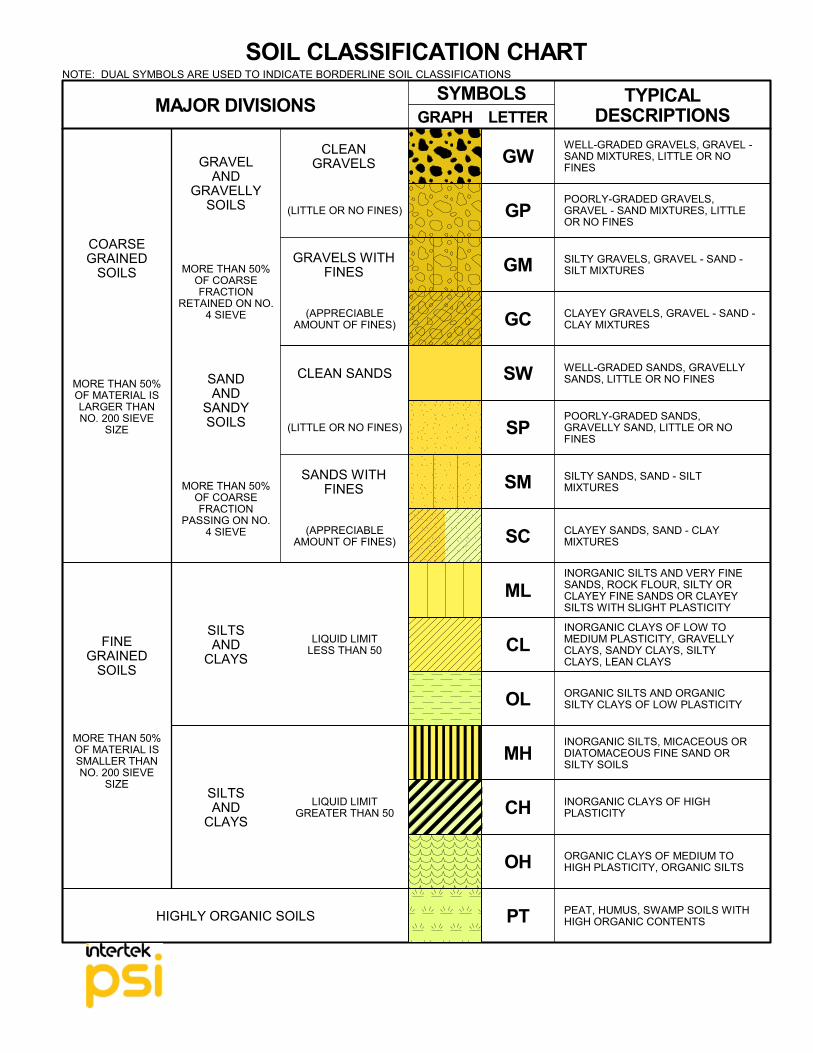
The Unified Soil Classification System (USCS), AASHTO 1988 and ASTM designations D2487 and D-2488 areused to identify the encountered materials unless otherwise noted. Coarse-grained soils are defined as havingmore than 50% of their dry weight retained on a #200 sieve (0.075mm); they are described as: boulders,cobbles, gravel or sand. Fine-grained soils have less than 50% of their dry weight retained on a #200 sieve;they are defined as silts or clay depending on their Atterberg Limit attributes. Major constituents may be addedas modifiers and minor constituents may be added according to the relative proportions based on grain size.
DescriptionFlat:
Elongated:Flat & Elongated:
DescriptionAngular:
Subangular:
Subrounded:
Rounded:
Criteria Particles with width/thickness ratio > 3Particles with length/width ratio > 3Particles meet criteria for both flat andelongated
Descriptive TermTrace:With:
Modifier:
Size Range Over 300 mm (>12 in.)75 mm to 300 mm (3 in. to 12 in.)19 mm to 75 mm (¾ in. to 3 in.)4.75 mm to 19 mm (No.4 to ¾ in.)2 mm to 4.75 mm (No.10 to No.4)0.42 mm to 2 mm (No.40 to No.10)0.075 mm to 0.42 mm (No. 200 to No.40)0.005 mm to 0.075 mm<0.005 mm
Component Boulders:Cobbles:
Coarse-Grained Gravel:Fine-Grained Gravel:
Coarse-Grained Sand:Medium-Grained Sand:
Fine-Grained Sand:Silt:
Clay:
ANGULARITY OF COARSE-GRAINED PARTICLESRELATIVE DENSITY OF COARSE-GRAINED SOILS
N - Blows/foot
0 - 44 - 10
10 - 3030 - 5050 - 80
80+
Relative Density
Very LooseLoose
Medium DenseDense
Very DenseExtremely Dense
RELATIVE PROPORTIONS OF FINES
% Dry Weight< 5%
5% to 12%>12%
Standard "N" penetration: Blows per foot of a 140 pound hammer falling 30 inches on a 2-inch O.D.Split-Spoon.A "N" penetration value corrected to an equivalent 60% hammer energy transfer efficiency (ETR)Unconfined compressive strength, TSFPocket penetrometer value, unconfined compressive strength, TSFMoisture/water content, %Liquid Limit, %Plastic Limit, %Plasticity Index = (LL-PL),%Dry unit weight, pcfApparent groundwater level at time noted
Criteria Particles have sharp edges and relatively planesides with unpolished surfacesParticles are similar to angular description, but haverounded edgesParticles have nearly plane sides, but havewell-rounded corners and edgesParticles have smoothly curved sides and no edges
Solid Flight Auger - typically 4" diameterflights, except where noted.Hollow Stem Auger - typically 3¼" or 4¼ I.D.openings, except where noted.Mud Rotary - Uses a rotary head withBentonite or Polymer SlurryDiamond Bit Core SamplerHand AugerPower Auger - Handheld motorized auger
MOISTURE CONDITION DESCRIPTIONCONSISTENCY OF FINE-GRAINED SOILS
DescriptionBlocky:
Lensed:Layer:Seam:
Parting:
DescriptionStratified:
Laminated:
Fissured:
Slickensided:
STRUCTURE DESCRIPTION
QU - TSF
Extremely SoftVery Soft
SoftMedium Hard
Moderately HardHard
Very Hard
SCALE OF RELATIVE ROCK HARDNESS ROCK BEDDING THICKNESSES
Consistency
Criteria Alternating layers of varying material or color withlayers at least ¼-inch (6 mm) thickAlternating layers of varying material or color withlayers less than ¼-inch (6 mm) thickBreaks along definite planes of fracture with littleresistance to fracturingFracture planes appear polished or glossy,sometimes striated
Criteria Greater than 3-foot (>1.0 m)1-foot to 3-foot (0.3 m to 1.0 m)4-inch to 1-foot (0.1 m to 0.3 m)1¼-inch to 4-inch (30 mm to 100 mm)½-inch to 1¼-inch (10 mm to 30 mm)1/8-inch to ½-inch (3 mm to 10 mm)1/8-inch or less "paper thin" (<3 mm)
Void Diameter <6 mm (<0.25 in)6 mm to 50 mm (0.25 in to 2 in)50 mm to 600 mm (2 in to 24 in)>600 mm (>24 in)
ROCK QUALITY DESCRIPTION
RQD Value90 -10075 - 9050 - 7525 -50
Less than 25
Size Range >4.76 mm2.0 mm - 4.76 mm0.42 mm - 2.0 mm0.075 mm - 0.42 mm<0.075 mm
Rock generally fresh, joints stained and discolorationextends into rock up to 25 mm (1 in), open joints maycontain clay, core rings under hammer impact.
Rock mass is decomposed 50% or less, significantportions of the rock show discoloration andweathering effects, cores cannot be broken by handor scraped by knife.
Rock mass is more than 50% decomposed, completediscoloration of rock fabric, core may be extremelybroken and gives clunk sound when struck byhammer, may be shaved with a knife.
Rock Mass DescriptionExcellent
GoodFairPoor
Very Poor
DEGREE OF WEATHERING
Slightly Weathered:
Weathered:
Highly Weathered:
Criteria Cohesive soil that can be broken down into smallangular lumps which resist further breakdownInclusion of small pockets of different soilsInclusion greater than 3 inches thick (75 mm)Inclusion 1/8-inch to 3 inches (3 to 75 mm) thickextending through the sampleInclusion less than 1/8-inch (3 mm) thick
Very SoftSoft
Firm (Medium Stiff)Stiff
Very StiffHard
Very Hard
Page 2 of 2
OH
CH
MH
OL
CL
ML
SC
SM
SP
COARSEGRAINED
SOILS
SW
TYPICALDESCRIPTIONS
WELL-GRADED GRAVELS, GRAVEL -SAND MIXTURES, LITTLE OR NOFINES
POORLY-GRADED GRAVELS,GRAVEL - SAND MIXTURES, LITTLEOR NO FINES
SILTY GRAVELS, GRAVEL - SAND -SILT MIXTURES
LETTERGRAPH
SYMBOLSMAJOR DIVISIONS
SOIL CLASSIFICATION CHART
PT
GC
GM
GP
GW
CLAYEY GRAVELS, GRAVEL - SAND -CLAY MIXTURES
WELL-GRADED SANDS, GRAVELLYSANDS, LITTLE OR NO FINES
POORLY-GRADED SANDS,GRAVELLY SAND, LITTLE OR NOFINES
SILTY SANDS, SAND - SILTMIXTURES
CLAYEY SANDS, SAND - CLAYMIXTURES
INORGANIC SILTS AND VERY FINESANDS, ROCK FLOUR, SILTY ORCLAYEY FINE SANDS OR CLAYEYSILTS WITH SLIGHT PLASTICITY
Intertek For more than 135 years, companies around the world have depended on Intertek to help ensure the quality and safety of their products, processes and systems.
We go beyond testing, inspecting and certifying products; we are a Total Quality Assurance provider to industries worldwide. Through our global network of state-of-the-art facilities and industry-leading technical expertise we provide innovative and bespoke Assurance, Testing, Inspection and Certification services to customers. We provide a systemic approach to supporting our customers’ Quality Assur-ance efforts in each of the areas of their operations including R&D, raw materials sourcing, compo-nents suppliers, manufacturing, transportation, distribution and retail channels, and consumer man-agement. Intertek is an industry leader with more than 42,000 employees in 1,000 locations in over 100 countries. We deliver Quality Assurance expertise 24 hours a day, 7 days a week with our industry-winning processes and customer-centric culture. Whether your business is local or global, we can help to ensure that your products meet quali-ty, health, environmental, safety, and social accountability stand-ards for virtually any market around the world. We hold extensive global accreditations, recognitions, and agreements, and our knowledge of and expertise in overcoming regulatory, market, and supply chain hurdles is unrivaled.
Intertek can sharpen your competitive edge
• With reliable testing and certification for faster regulatory approval
• Through rapid, efficient entry to virtually any market in the world
• With Total Quality Assurance across your supply chain
• Through innovative leadership in meeting social accountability standards
• By reducing cost and minimizing health, safety, and security risks
• By becoming a TRUSTED BRAND
Our Mission To exceed our customers’
expectations with innovative and
bespoke Assurance, Testing,
Inspection and Certification
services for their operations and
supply chain.
Globally. 24/7.
WHO WE ARE
STATEMENT OF QUALIFICATIONS
PSI Professional Service Industries, Inc. (PSI), an Intertek company, nationally recognized consulting engi-neering and testing firm providing integrated services in several disciplines, including environmental consulting, building envelope consulting and testing, geotechnical engineering, construction materials testing and engineering, asbestos management and facilities engineering and consulting. We are rec-ognized as one of the largest engineering design consulting companies in the US. We have been providing engineering consulting services to Fortune 500 clients and governmental agencies for over 100 years. However, our proudest accomplishment is the large number of clients that we have ser-viced for many years that keep coming back because of our responsiveness, commitment to listening to our clients, and consistent quality of service. PSI has been providing business and industry with objective, accurate and useful information for more than 100 years. Today, we employ approximately 2,300 skilled personnel in 100 offices nationwide. Distinguished as both a local and a national leader in engineering and environmental services, PSI is recognized in several disciplines including the following:
• Geotechnical Engineering
• Construction Materials Testing and Special Inspection
• Environmental Consulting
• Industrial Hygiene
• Nondestructive Examination
• Pavement Evaluation Services
• Building Science Solutions
• Building Envelope
• Curtainwall
• Acoustic
• Fire/Life Safety
• Technology
• Roof Consulting
PSI provides its clients with Information To Build On in making knowledgeable, cost-effective business decisions that help their clients reduce expenses, improve quality and decrease liabilities.
A Commitment To Excellence
PSI maintains the highest professional and ethical standards, which include an economic awareness to provide the highest quality of personnel and service at a reasonable cost to our clients. Our unique combination of local, independent offices and nationwide resources means our project managers have the full responsibility for managing your local projects, and also have the national resources to handle the most challenging and complex projects, regardless of size. While PSI’s growth has been notable, even more impressive has been our ability to grow without sacri-ficing our technical knowledge or personalized attention to our clients. Recognition of the importance of our clients and repeat business has been a key factor in PSI’s success. PSI will not sacrifice quality, value, or service to our clients.
PSI can provide outstanding
consulting engineering and testing
services; however, most of all we
desire to demonstrate our
commitment to excellence.
WHO WE ARE
STATEMENT OF QUALIFICATIONS
PSI’s Vision… is to be the most trusted, integrated provider of “Information To Build On” for
clients that buy, sell, design, construct, develop, finance and manage properties and
infrastructure. By being safe 24/7/365, hiring and retaining the best employees, efficiently
managing projects, and building close client relationships, we will be successful in growing
PSI and in balancing the needs of our employees, clients and investors.
A Commitment To Excellence (continued)
Our staff of professionals consists of the following:
• Professional Engineers (PE/PEng)
• Registered Roof Consultants (RRC)
• Registered Architects (AIA)
• Certified Industrial Hygienists (CIH)
Our field and laboratory technicians are trained in-house and at special schools and seminars. Our project managers and technicians are certified by associations such as the following and also work with other specialized organizations within each discipline.
• Roofing Industry Educational Institute (RIEI)
• Roof Consultants Institute (RCI)
• American Concrete Institute (ACI)
• National Institute for the Certification of Engineering Technicians (NICET)
• American Welding Society (AWS)
• International Code Council (ICC)
• International Fire Council (IFC)
Since our founding, we have dedicated ourselves to excellence both in our technical expertise and in customer service. It is this principal upon which we have based our organization and established a national reputation as a leader in the field of professional engineering, testing and consulting services.