SEISMIC ANALYSIS USING LUMPED MASS METHOD Create the Geometry of the model and give member property. Provide all beam and column junctions as hinged and create a load case [i.e. DL+50%LL or 25%LL as per Code IS 1893 (Part 1) -2002] Then run analysis and view the result w.r.t the already created load case. Go to reaction tab and copy the reactions to the excel sheet. Delete the all the unwanted columns [ Fx, Fz, Mx, My…] Let nodes, load case and Fy column retained Replace the load case column fully by Joint weight. Copy and paste it in the staad editor. Done… Detailed Procedure : STEPS INVOLVED: 1. Creation of Geometry 2. Giving Member Property 3. Support Condition 4. Giving Loads : Load 1 Dead Load Load 2 Live Load Load Comb 3 5. Specifying Analysis Type 6. Post Analysis Print 7. Design 8. Analysis. (1) In this complete steps 1 to 6. Then follow the further steps for Lumped Mass. There are two parts. Part 1 : Finding Joint Loads for Earth quake analysis. Part 2: Applying Earthquake analysis. Before Proceeding take a copy of Model created from step 1 to 6. Part 1: To find Joint Loads: 1.To give pinned supports at all column nodes : Main menu ‡ Select ‡ Beams parallel to ‡Y
Transcript
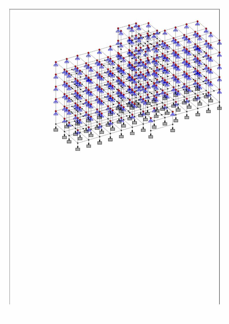
SEISMIC ANALYSIS USING LUMPED MASS METHOD
Create the Geometry of the model and give member property.Provide all beam and column junctions as hinged and create a load case [i.e. DL+50%LL or 25%LL as per Code IS 1893 (Part 1) -2002]Then run analysis and view the result w.r.t the already created load case.Go to reaction tab and copy the reactions to the excel sheet.Delete the all the unwanted columns [ Fx, Fz, Mx, My…]Let nodes, load case and Fy column retainedReplace the load case column fully by Joint weight.Copy and paste it in the staad editor.Done…Detailed Procedure :
STEPS INVOLVED:
1. Creation of Geometry
2. Giving Member Property
3. Support Condition
4. Giving Loads :
Load 1 Dead Load
Load 2 Live Load
Load Comb 3
5. Specifying Analysis Type
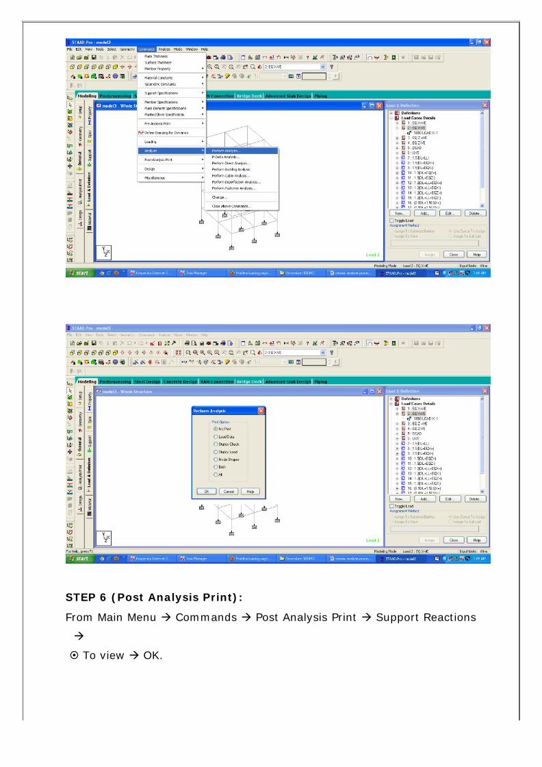
6. Post Analysis Print
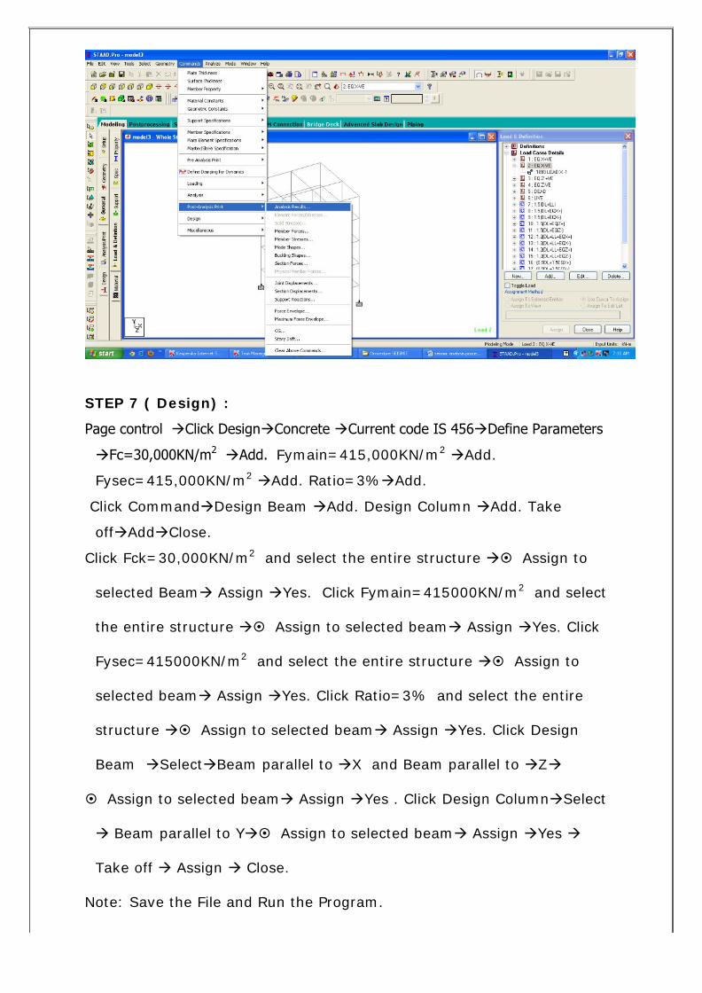
7. Design
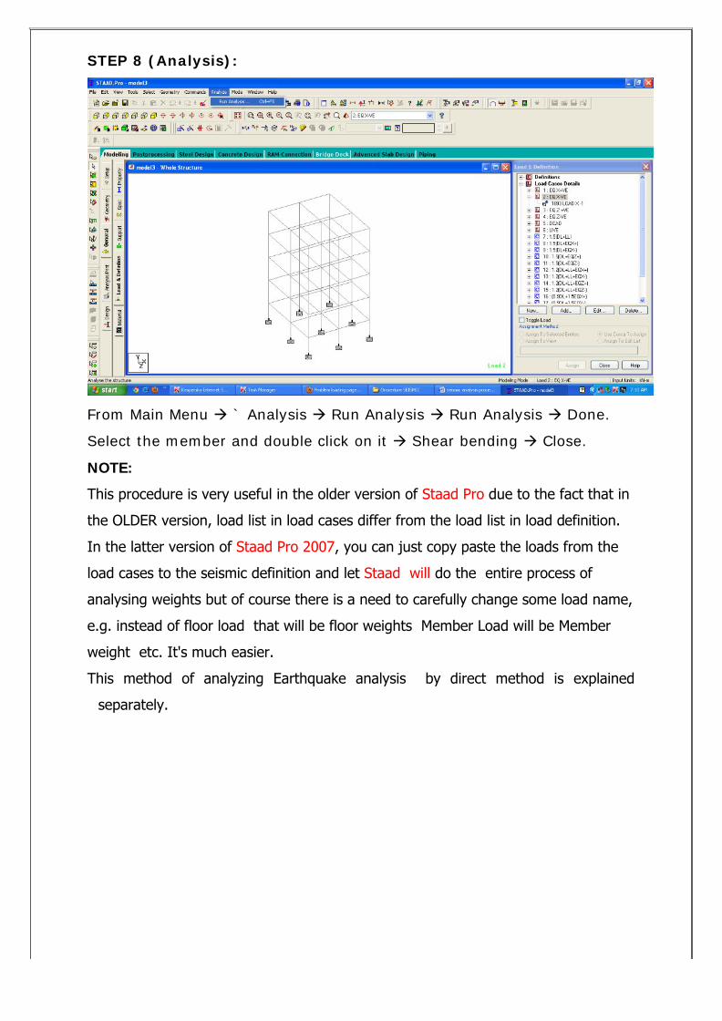
8. Analysis.
(1) In this complete steps 1 to 6. Then follow the further steps for Lumped
Mass.
There are two parts.
Part 1 : Finding Joint Loads for Earth quake analysis.
Part 2: Applying Earthquake analysis.
Before Proceeding take a copy of Model created from step 1 to 6.
Part 1: To find Joint Loads:
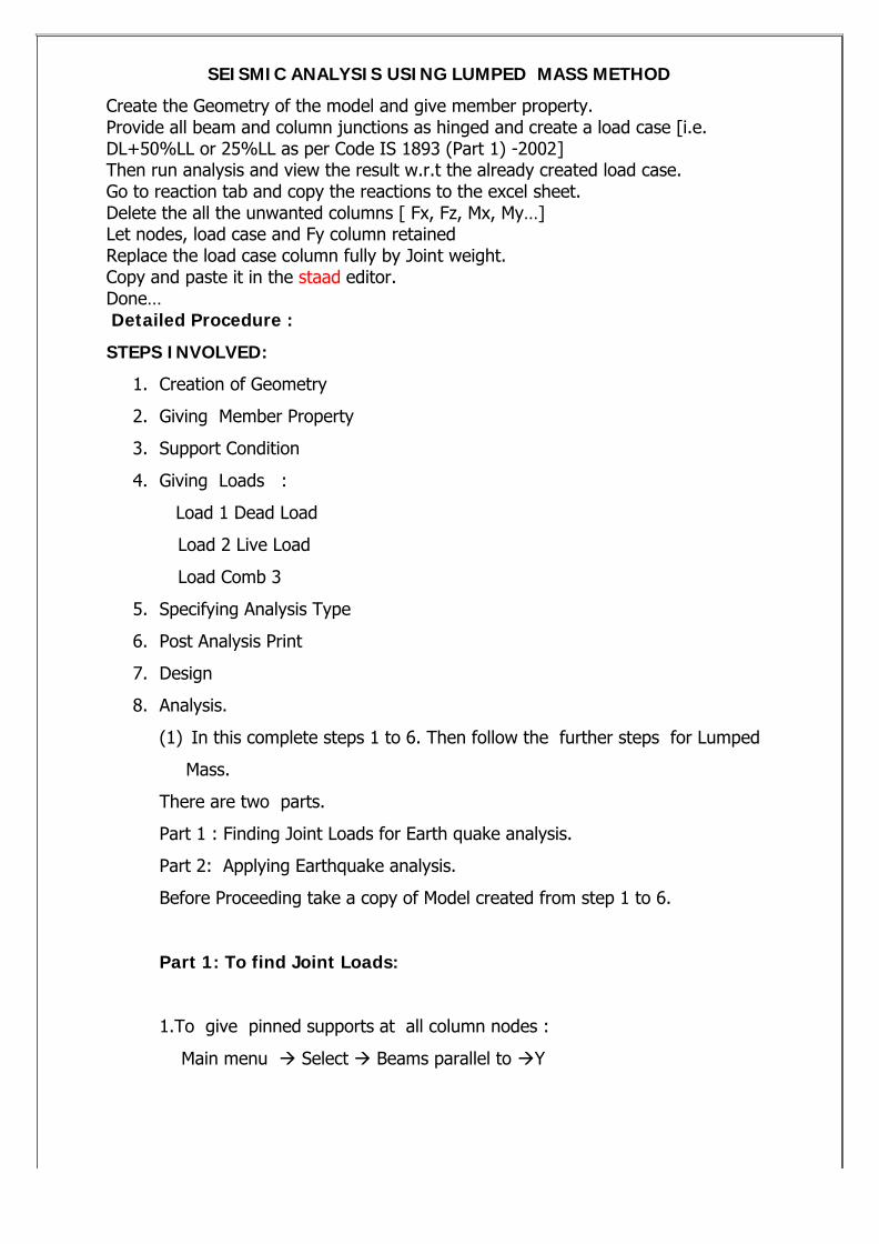
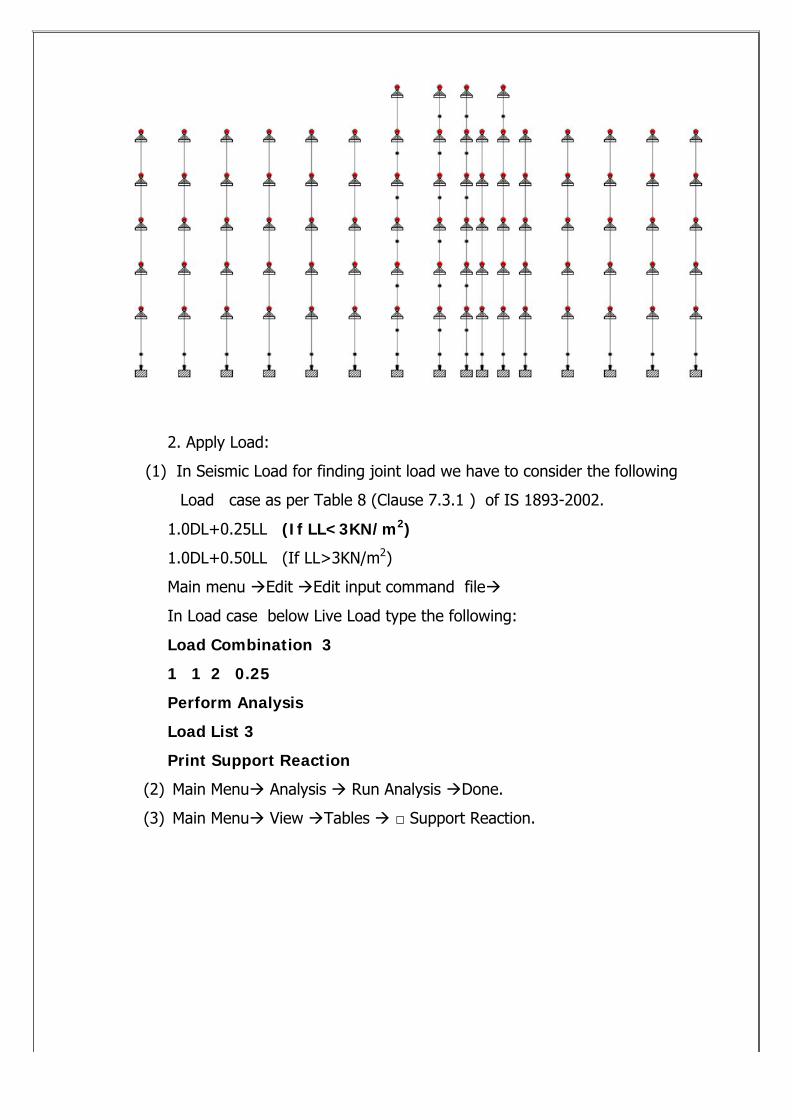
1.To give pinned supports at all column nodes :
Main menu ‡ Select ‡ Beams parallel to ‡Y
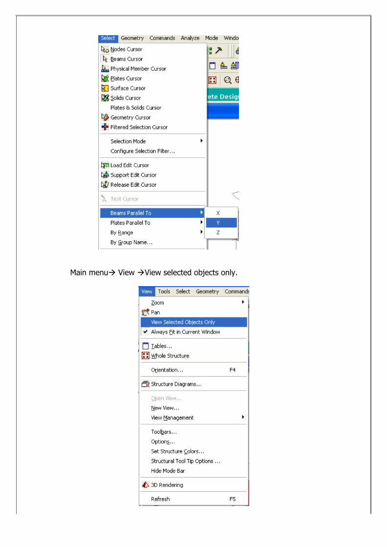
Main menu‡ View ‡View selected objects only.
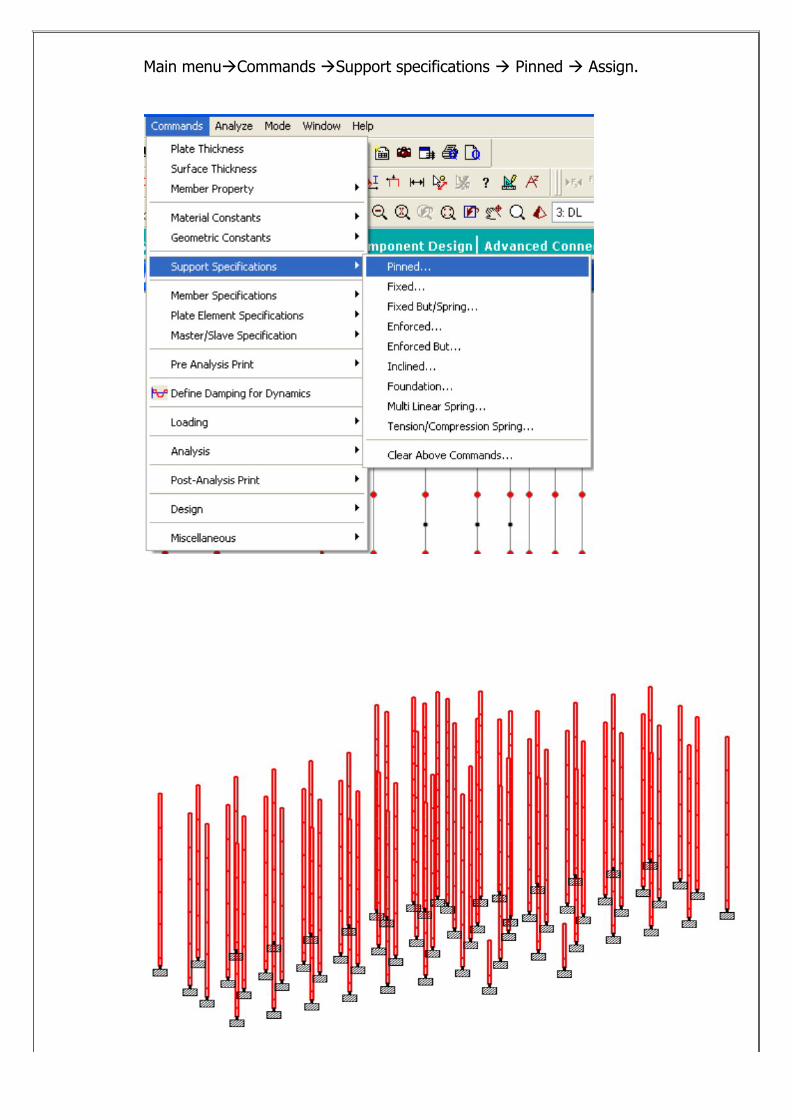
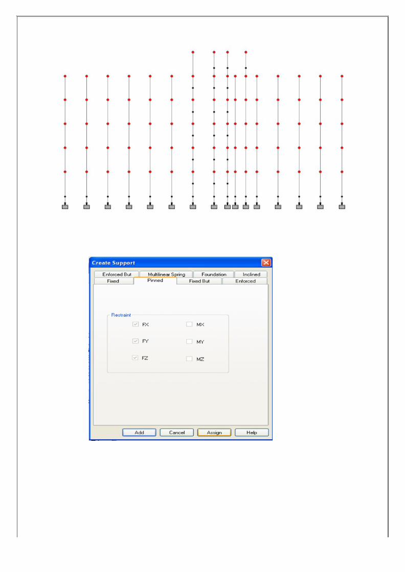
Main menu‡Commands ‡Support specifications ‡ Pinned ‡ Assign.
2. Apply Load:
(1) In Seismic Load for finding joint load we have to consider the following
Load case as per Table 8 (Clause 7.3.1 ) of IS 1893-2002.
1.0DL+0.25LL (If LL<3KN/m2)
1.0DL+0.50LL (If LL>3KN/m2)
Main menu ‡Edit ‡Edit input command file‡
In Load case below Live Load type the following:
Load Combination 3
1 1 2 0.25
Perform Analysis
Load List 3
Print Support Reaction
(2) Main Menu‡ Analysis ‡ Run Analysis ‡Done.
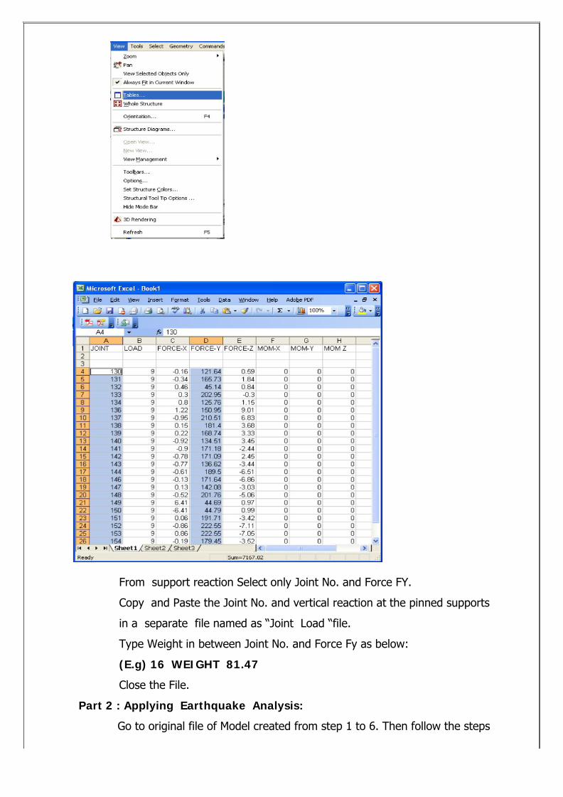
(3) Main Menu‡ View ‡Tables ‡ □ Support Reaction.
From support reaction Select only Joint No. and Force FY.
Copy and Paste the Joint No. and vertical reaction at the pinned supports
in a separate file named as “Joint Load “file.
Type Weight in between Joint No. and Force Fy as below:
(E.g) 16 WEIGHT 81.47
Close the File.
Part 2 : Applying Earthquake Analysis:
Go to original file of Model created from step 1 to 6. Then follow the steps
below:
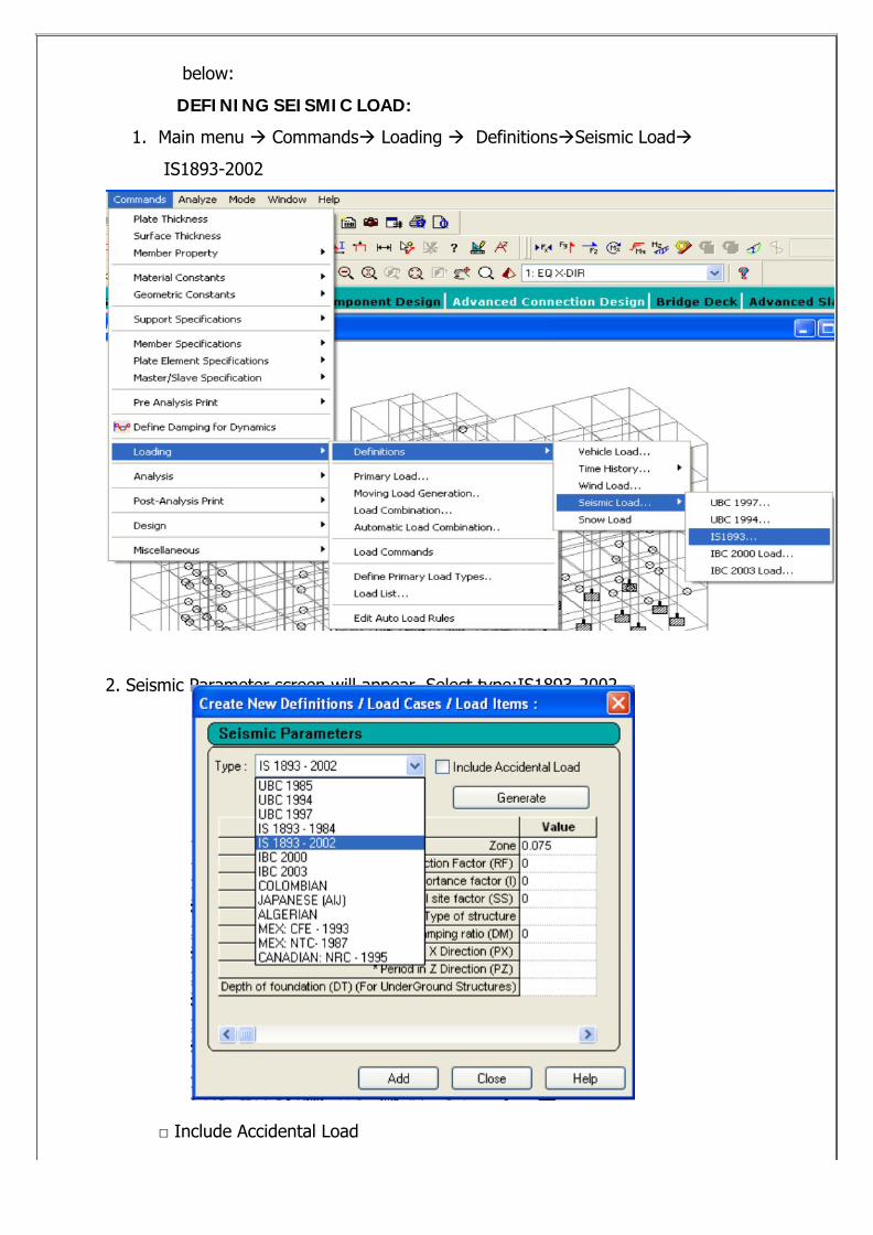
DEFINING SEISMIC LOAD:
1. Main menu ‡ Commands‡ Loading ‡ Definitions‡Seismic Load‡
IS1893-2002
2. Seismic Parameter screen will appear. Select type:IS1893-2002.
□ Include Accidental Load
□ Generate .
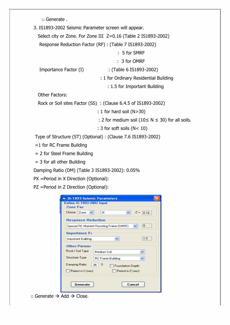
3. IS1893-2002 Seismic Parameter screen will appear.
Select city or Zone. For Zone III Z=0.16 (Table 2 IS1893-2002)