30
Senior Seminar Project: Robotic Pong Player Braden Elliott

Senior Seminar Project:
Robotic Pong Player
Braden Elliott
Table of Contents
Introduction .................................................................................................................................... 4
Statement of Problem ..................................................................................................................... 4
Client Specifications .................................................................................................................... 4
Project Design ................................................................................................................................. 4
Electrical Design .......................................................................................................................... 4
Mechanical Design .................................................................................................................... 10
Software Design ........................................................................................................................ 11
Economic Constraints ............................................................................................................... 12
Results ........................................................................................................................................... 13
Implications for Future Work ........................................................................................................ 13
References .................................................................................................................................... 14
Appendices .................................................................................................................................... 15
Appendix A: Arm Controls Header and Source Code Files ....................................................... 15
Appendix B: Main Source Code File for Arm Movement Demo ............................................... 27
Appendix C: Image Recognition Code File ................................................................................ 29

Table of Figures
Figure 1: PCB Parts List.................................................................................................................... 5
Figure 2: Circuit Schematic ............................................................................................................. 7
Figure 3: PCB Board Layout ............................................................................................................. 8
Figure 4: PCB ................................................................................................................................... 9
Figure 5: Arm Modeling ................................................................................................................ 10
Figure 6: Robotic Arm ................................................................................................................... 11

Introduction
A fun, simple game such a beer pong played between two humans is a great time.
Bringing a robot into the mix could be an even better one. One arm, one eye, and a brain are
needed to play, so make a robotic arm to throw ping pong balls, a camera to see where the ping
pong balls go, and program a computer to decide what to do next in the game to win against
the human.
Statement of Problem The project is to design and build a robotic arm to be able to pick up and throw a ping
pong ball and program a computer to interface with the arm and a camera to recognize where
the ball was through relative to the cup layout and tell the arm what to do next. The visual
feedback should tell whether the ball landed in a cup along with the specific cup it landed in.
Client Specifications The client requires a proven concept of a robotic machine capable of performing the
necessary tasks to play a human in a physical game such as pong. There should be a multi-
jointed arm moving with multiple axis, image processing feedback, and external communication
capability.
Project Design
Electrical Design
The arm is controlled via a custom motherboard which includes; one STM32F446RE
microcontroller (Semiconductor Manufacturing, 2018) for I/O, two dual-H-bridges for dc

motors, several pull-up circuits for servo motors, USB port for computer communication, three
buck converters for power, and a transformer/rectifier circuit for wall power capability. The full
list of components is shown in Table 1.
Part Value Device Description B1 SKB SEMIKRON RECTIFIER C1 100n C-USC0603K CAPACITOR C2 100n C-USC0603K CAPACITOR C3 100n C-USC0603K CAPACITOR C4 100n C-USC0603K CAPACITOR C5 100n C-USC0603K CAPACITOR C6 100n C-USC0603K CAPACITOR C7 100n C-USC0603K CAPACITOR C8 4.7u C-USC0603K CAPACITOR C9 100n C-USC0603K CAPACITOR C10 1u C-US150-054X183 CAPACITOR C11 1u C-US150-054X183 CAPACITOR C12 1u C-USC0603K CAPACITOR JP1 PINHD-2X10 PIN HEADER LED1 LED_E LED R1 10k R-US_MELF0204W RESISTOR R2 510 R-US_MELF0204W RESISTOR R3 100k R-US_MELF0204W RESISTOR S1 SKHMPSE010 6.2 X 6.5mm TACT Switch (SMD) SERVO_SUPPLY PINHD-2X5 PIN HEADER ST-LINK PINHD-1X4 PIN HEADER U$1 SN754410NE Quadruple Half-H Driver U$2 MOTOR_241F8X Motor with an encoder U$3 MOTOR_241F8X Motor with an encoder U$4 SN754410NE Quadruple Half-H Driver U$5 MOTOR_241F8X Motor with an encoder U$6 STM32F446RE U$7 POLOLU_BUCK U$8 POLOLU_BUCK U$9 POLOLU_BUCK U$11 +/- U$12 TRANSFORMER_PSS5-12 Transformer U$13 +/- X1 MINI-USB_SHIELD5P4-32005-400 MINI USB-B R/A W/O POST 5 pol.
Figure 1: PCB Parts List
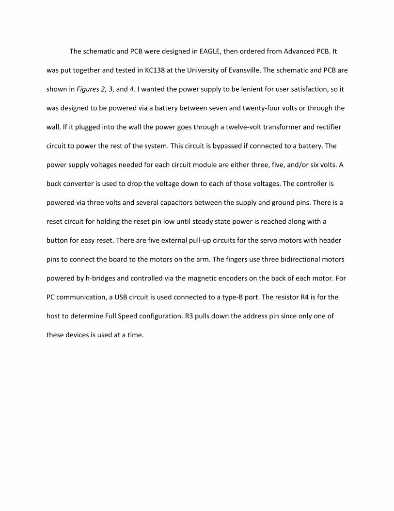
The schematic and PCB were designed in EAGLE, then ordered from Advanced PCB. It
was put together and tested in KC138 at the University of Evansville. The schematic and PCB are
shown in Figures 2, 3, and 4. I wanted the power supply to be lenient for user satisfaction, so it
was designed to be powered via a battery between seven and twenty-four volts or through the
wall. If it plugged into the wall the power goes through a twelve-volt transformer and rectifier
circuit to power the rest of the system. This circuit is bypassed if connected to a battery. The
power supply voltages needed for each circuit module are either three, five, and/or six volts. A
buck converter is used to drop the voltage down to each of those voltages. The controller is
powered via three volts and several capacitors between the supply and ground pins. There is a
reset circuit for holding the reset pin low until steady state power is reached along with a
button for easy reset. There are five external pull-up circuits for the servo motors with header
pins to connect the board to the motors on the arm. The fingers use three bidirectional motors
powered by h-bridges and controlled via the magnetic encoders on the back of each motor. For
PC communication, a USB circuit is used connected to a type-B port. The resistor R4 is for the
host to determine Full Speed configuration. R3 pulls down the address pin since only one of
these devices is used at a time.

Figure 2: Circuit Schematic

Figure 3: PCB Board Layout

Figure 4: PCB

Mechanical Design The arm was built using 3D printed materials, Miuzei 996R MG servo motors, Pololu
241F8X dc motors, and extruded aluminum. The 3D parts were modeled in Autodesk Inventor,
then printed on a Prusa I3 printer. The models are shown in Figure 5 and the printed pieces are
shown in Figure 6.
Figure 5: Arm Modeling

Figure 6: Robotic Arm
Software Design To control the arm, a program was written in a Keil project in embedded C. The main
source file shown in Appendix B runs a sequence of functions from the motor control file to
move each of the motors on the arm. This file also includes the interrupt function definitions
for clearing the controller’s timer interrupt flags for the pulse width modulation period cycles.
The motor control source files in Appendix A contain all controls of the motors on the arm. The
prototypes are given in the first file and the definitions in the second. The header file also
includes define statements for initializing constants used for initial motor output. A servo_t
type is defined and used for enumerating servo motors. The MOTOR_CONTROL_INIT function

initializes all peripherals needed to output to the arm. Six external interrupt functions are
defined to monitor edge detections on six I/O pins connected to the encoders on the finger
motors. Motor_Move calculates the number of edges to occur to move a given number of
degrees of rotation then turns on the motors for that number of edge counts. Servo_MoveTo
calculates the difference in pulse width between each of the current servo states and their next
states, adjusting their position incrementally at the same time for a fluid-like movement (also
helps with current spikes). There are also two functions for time delaying given a number of
microseconds or milliseconds using the controller’s basic timers.
For visual feedback, an image recognition process was written in Octave as shown in
Appendix C. The image is put through a Low Pass Filter to get edge detection. Since the
resulting edges vary in intensity, a histogram is used to figure out a good point to perform a
cutoff filter to show the major edges the recognition cares about.
Economic Constraints
Most of the body is made using 3D printed plastics, making it cheap and efficient in
material requirements. Socially, this is an ideal product for bringing people close together
through the fun of the game. Politically, people can use this as a means of compromising their
opinions and beliefs when they lose a game. For health reasons, it his highly suggested any
distributor of this product reinforce the importance of drinking responsibly. Manufacturability
is taken care of through each component used in this product already being manufactured
regularly, except for 3D printed parts which are easy to manufacture, along with software
which is also easy to distribute. Sustainability is not able to be tested due to the timeframe of
this project only being one year, the final product needs an extension to test durability. The
final product will be safety tested. It will include a temperature sensor reading temperature in
areas where heat may be an issue, such as H-bridge drivers and power supply converters. The
range of motion the arm can act in will be constrained to minimalize human interaction
hazards.
Results
The arm was designed, built, and programmed to grab a ball and move it around. Each
of the motors is controlled via a custom PCB with an STM32F446RE microcontroller. An image
of the pong layout can be given to the octave program for image recognition. The arm failed to
play a game of pong nor throw a ball. Current spikes happen regularly, leaving the arm unable
to move correctly. The two motors that work inverse of each other to move the base joint of
the arm often come out of sink with each other, causing tension and damage to the system.
Implications for Future Work
Future modifications include changing: the dual inverse servo motors to a high-power
motor with an encoder and gear box, the three finger motors to one motor and a gear system,
the bottom servo motor to a stepper motor, the decision-making algorithm to a trained
recurrent neural network (Wikipedia, 2019) trained via reinforcement learning (Wikipedia,
2019).

References
Semiconductor Manufacturing. (2018). STM32L432KC. Retrieved from ST:
https://www.st.com/en/microcontrollers/stm32l432kc.html
Wikipedia. (2019, March 28). Recurrent Neural Network. Retrieved from wiki:
https://en.wikipedia.org
Wikipedia. (2019, April 24). Reinforcement Learning. Retrieved from wiki:
https://en.wikipedia.org

Appendices
Appendix A: Arm Controls Header and Source Code Files
1. /** 2. * Author: Braden Elliott 3. * 4. * motor_control.h 5. * header file for the robotic arm servos 6. */ 7. 8. #ifndef MOTOR_CONTROL_H_INCLUDED 9. #define MOTOR_CONTROL_H_INCLUDED 10. 11. #define MIN_SERVO_PWM 1500 12. #define MAX_SERVO_PWM 5595 13. #define MOTOR_SPEED_PWM 20000 14. #define MOTOR_OFF_PWM 0 15. #define POLOLU_2385_TURN_MULTIPLIER 9.43 16. 17. #define SB_StartValue 3500 18. #define SMJ_StartValue 3060 19. #define STJ_StartValue 2620 20. 21. /* 50% */ 22. #define SBJL_StartValue 3340 23. #define SBJR_StartValue 3140 24. 25. typedef enum { 26. SB, // Servo Base 27. SMJ, // Servo Middle Joint 28. STJ, // Servo Top Joint 29. SBJ // Servo Bottom Joint 30. } servo_t; 31. 32. typedef enum { false, true } bool_t; 33. 34. /** 35. * method: MOTOR_CONTROL_INIT 36. * discription: initialize I/O, interrupts, & timers to perform
motor/encoder 37. */ void MOTOR_CONTROL_INIT(void); 38. 39. void Motor_Clockwise(void); 40. void Motor_Counterclockwise(void); 41. void Motor_Stop(void); 42. void Motor_Move(int16_t); 43. 44. void Servo_MoveTo(servo_t, uint16_t[4]); 45. 46. void Basic_msec_Delay(uint16_t); 47. void Basic_usec_Delay(uint16_t); 48.

49. #endif
1. /** 2. * Author: Braden Elliott 3. * 4. * motor_control.c 5. * source file for the robotic arm motors 6. */ 7. 8. #include "stm32f446xx.h" 9. #include "motor_control.h" 10. #include <math.h> 11. 12. void MOTOR_CONTROL_INIT(void) 13. { 14. uint32_t tmp_reg; 15. 16. /* Clock Enables */ 17. tmp_reg = RCC->AHB1ENR; 18. tmp_reg |= RCC_AHB1ENR_GPIOAEN; 19. tmp_reg |= RCC_AHB1ENR_GPIOBEN; 20. tmp_reg |= RCC_AHB1ENR_GPIOCEN; 21. RCC->AHB1ENR = tmp_reg; 22. 23. tmp_reg = RCC->APB1ENR; 24. tmp_reg |= RCC_APB1ENR_TIM3EN; 25. tmp_reg |= RCC_APB1ENR_TIM4EN; 26. tmp_reg |= RCC_APB1ENR_TIM6EN; 27. tmp_reg |= RCC_APB1ENR_TIM7EN; 28. RCC->APB1ENR = tmp_reg; 29. 30. tmp_reg = RCC->APB2ENR; 31. tmp_reg |= RCC_APB2ENR_TIM1EN; 32. RCC->APB2ENR = tmp_reg; 33. 34. 35. /* Servos: (ordered as on pcb) 36. * PA10, TIM1_3: SB - Servo Base 37. * PA9 , TIM1_2: SMJ - Servo Middle Joint 38. * PA8 , TIM1_1: STJ - Servo Top Joint 39. * PB9 , TIM4_3: SBJL - Servo Bottom Joint Left 40. * PB8 , TIM4_4: SBJR - Servo Bottom Joint Right 41. */ 42. tmp_reg = GPIOA->MODER; 43. tmp_reg &= ~GPIO_MODER_MODER10; 44. tmp_reg |= GPIO_MODER_MODER10_1; 45. tmp_reg &= ~GPIO_MODER_MODER9; 46. tmp_reg |= GPIO_MODER_MODER9_1; 47. tmp_reg &= ~GPIO_MODER_MODER8; 48. tmp_reg |= GPIO_MODER_MODER8_1; 49. GPIOA->MODER = tmp_reg; 50. 51. tmp_reg = GPIOA->OTYPER;

52. tmp_reg |= GPIO_OTYPER_OT10; 53. tmp_reg |= GPIO_OTYPER_OT9; 54. tmp_reg |= GPIO_OTYPER_OT8; 55. GPIOA->OTYPER = tmp_reg; 56. 57. tmp_reg = GPIOA->AFR[1]; 58. tmp_reg &= ~GPIO_AFRH_AFSEL10; 59. tmp_reg |= 1 << GPIO_AFRH_AFSEL10_Pos; 60. tmp_reg &= ~GPIO_AFRH_AFSEL9; 61. tmp_reg |= 1 << GPIO_AFRH_AFSEL9_Pos; 62. tmp_reg &= ~GPIO_AFRH_AFSEL8; 63. tmp_reg |= 1 << GPIO_AFRH_AFSEL8_Pos; 64. GPIOA->AFR[1] = tmp_reg; 65. 66. tmp_reg = GPIOB->MODER; 67. tmp_reg &= ~GPIO_MODER_MODER9; 68. tmp_reg |= GPIO_MODER_MODER9_1; 69. tmp_reg &= ~GPIO_MODER_MODER8; 70. tmp_reg |= GPIO_MODER_MODER8_1; 71. GPIOB->MODER = tmp_reg; 72. 73. tmp_reg = GPIOB->OTYPER; 74. tmp_reg |= GPIO_OTYPER_OT9; 75. tmp_reg |= GPIO_OTYPER_OT8; 76. GPIOB->OTYPER = tmp_reg; 77. 78. tmp_reg = GPIOB->AFR[1]; 79. tmp_reg &= ~GPIO_AFRH_AFSEL9; 80. tmp_reg |= 2 << GPIO_AFRH_AFSEL9_Pos; 81. tmp_reg &= ~GPIO_AFRH_AFSEL8; 82. tmp_reg |= 2 << GPIO_AFRH_AFSEL8_Pos; 83. GPIOB->AFR[1] = tmp_reg; 84. 85. tmp_reg = TIM1->CCMR1; 86. tmp_reg &= ~TIM_CCMR1_OC1M_Msk; 87. tmp_reg |= 6 << TIM_CCMR1_OC1M_Pos; 88. tmp_reg |= TIM_CCMR1_OC1PE; 89. tmp_reg |= TIM_CCMR1_OC1FE; 90. tmp_reg &= ~TIM_CCMR1_OC2M_Msk; 91. tmp_reg |= 6 << TIM_CCMR1_OC2M_Pos; 92. tmp_reg |= TIM_CCMR1_OC2PE; 93. tmp_reg |= TIM_CCMR1_OC2FE; 94. TIM1->CCMR1 = tmp_reg; 95. 96. tmp_reg = TIM1->CCMR2; 97. tmp_reg &= ~TIM_CCMR2_OC3M_Msk; 98. tmp_reg |= 6 << TIM_CCMR2_OC3M_Pos; 99. tmp_reg |= TIM_CCMR2_OC3PE; 100. tmp_reg |= TIM_CCMR2_OC3FE; 101. TIM1->CCMR2 = tmp_reg; 102. 103. tmp_reg = TIM1->CCER; 104. tmp_reg |= TIM_CCER_CC1E; 105. tmp_reg |= TIM_CCER_CC2E; 106. tmp_reg |= TIM_CCER_CC3E; 107. TIM1->CCER = tmp_reg;

108. 109. TIM1->PSC = 7; 110. TIM1->ARR = 40000; 111. TIM1->CCR1 = STJ_StartValue; 112. TIM1->CCR2 = SMJ_StartValue; 113. TIM1->CCR3 = SB_StartValue; 114. TIM1->BDTR |= TIM_BDTR_MOE; 115. 116. tmp_reg = TIM1->CR1; 117. tmp_reg |= TIM_CR1_ARPE; 118. tmp_reg |= TIM_CR1_CEN; 119. TIM1->CR1 = tmp_reg; 120. 121. TIM1->EGR |= TIM_EGR_UG; 122. 123. tmp_reg = TIM4->CCMR2; 124. tmp_reg &= ~TIM_CCMR2_OC3M_Msk; 125. tmp_reg |= 6 << TIM_CCMR2_OC3M_Pos; 126. tmp_reg |= TIM_CCMR2_OC3PE; 127. tmp_reg |= TIM_CCMR2_OC3FE; 128. tmp_reg &= ~TIM_CCMR2_OC4M_Msk; 129. tmp_reg |= 6 << TIM_CCMR2_OC4M_Pos; 130. tmp_reg |= TIM_CCMR2_OC4PE; 131. tmp_reg |= TIM_CCMR2_OC4FE; 132. TIM4->CCMR2 = tmp_reg; 133. 134. tmp_reg = TIM4->CCER; 135. tmp_reg |= TIM_CCER_CC3E; 136. tmp_reg |= TIM_CCER_CC4E; 137. TIM4->CCER = tmp_reg; 138. 139. TIM4->PSC = 7; 140. TIM4->ARR = 40000; 141. TIM4->CCR3 = SBJL_StartValue; 142. TIM4->CCR4 = SBJR_StartValue; 143. 144. tmp_reg = TIM4->CR1; 145. tmp_reg |= TIM_CR1_ARPE; 146. tmp_reg |= TIM_CR1_CEN; 147. TIM4->CR1 = tmp_reg; 148. 149. 150. /* Pololu Motor: MC 151. * PB6 , TIM4_1: MC_M2 - Motor C M2 on hand 152. * PB7 , TIM4_2: MC_M1 - Motor C M1 on hand 153. * PB15, GP_Out: MC_En - Motor C Enable 154. * PC4 , EXTI : MC_OB - Motor C OutB 155. * PC5 , EXTI : MC_OA - Motor C OutA 156. */ 157. 158. tmp_reg = TIM4->CCMR1; 159. tmp_reg &= ~TIM_CCMR1_OC1M_Msk; 160. tmp_reg |= 6 << TIM_CCMR1_OC1M_Pos; 161. tmp_reg |= TIM_CCMR1_OC1PE; 162. tmp_reg |= TIM_CCMR1_OC1FE; 163. tmp_reg &= ~TIM_CCMR1_OC2M_Msk;

164. tmp_reg |= 6 << TIM_CCMR1_OC2M_Pos; 165. tmp_reg |= TIM_CCMR1_OC2PE; 166. tmp_reg |= TIM_CCMR1_OC2FE; 167. TIM4->CCMR1 = tmp_reg; 168. 169. tmp_reg = TIM4->CCER; 170. tmp_reg |= TIM_CCER_CC1E; 171. tmp_reg |= TIM_CCER_CC2E; 172. TIM4->CCER = tmp_reg; 173. 174. TIM4->CCR1 = MOTOR_OFF_PWM; 175. TIM4->CCR2 = MOTOR_OFF_PWM; 176. 177. NVIC_EnableIRQ(TIM4_IRQn); 178. TIM4->DIER |= TIM_DIER_CC1IE; 179. TIM4->DIER |= TIM_DIER_CC2IE; 180. 181. tmp_reg = GPIOB->MODER; 182. tmp_reg &= ~GPIO_MODER_MODER15; 183. tmp_reg |= GPIO_MODER_MODER15_0; 184. tmp_reg &= ~GPIO_MODER_MODER6; 185. tmp_reg |= GPIO_MODER_MODER6_1; 186. tmp_reg &= ~GPIO_MODER_MODER7; 187. tmp_reg |= GPIO_MODER_MODER7_1; 188. GPIOB->MODER = tmp_reg; 189. 190. tmp_reg = GPIOB->OTYPER; 191. tmp_reg |= GPIO_OTYPER_OT15; 192. GPIOB->OTYPER = tmp_reg; 193. 194. tmp_reg = GPIOB->AFR[0]; 195. tmp_reg &= ~GPIO_AFRL_AFSEL6; 196. tmp_reg |= 2 << GPIO_AFRL_AFSEL6_Pos; 197. tmp_reg &= ~GPIO_AFRL_AFSEL7; 198. tmp_reg |= 2 << GPIO_AFRL_AFSEL7_Pos; 199. GPIOB->AFR[0] = tmp_reg; 200. 201. tmp_reg = GPIOC->MODER; 202. tmp_reg &= ~GPIO_MODER_MODER4; 203. tmp_reg &= ~GPIO_MODER_MODER5; 204. GPIOC->MODER = tmp_reg; 205. 206. NVIC_EnableIRQ(EXTI4_IRQn); 207. NVIC_EnableIRQ(EXTI9_5_IRQn); 208. 209. tmp_reg = EXTI->IMR; 210. tmp_reg |= EXTI_EMR_EM4; 211. tmp_reg |= EXTI_EMR_EM5; 212. EXTI->IMR = tmp_reg; 213. 214. tmp_reg = EXTI->RTSR; 215. tmp_reg |= EXTI_RTSR_TR4; 216. tmp_reg |= EXTI_RTSR_TR5; 217. EXTI->RTSR = tmp_reg; 218. 219. tmp_reg = EXTI->FTSR;

220. tmp_reg |= EXTI_FTSR_TR4; 221. tmp_reg |= EXTI_FTSR_TR5; 222. EXTI->FTSR = tmp_reg; 223. 224. RCC->APB2ENR |= RCC_APB2ENR_SYSCFGEN; 225. SYSCFG->EXTICR[1] |= SYSCFG_EXTICR2_EXTI4_PC; 226. SYSCFG->EXTICR[1] |= SYSCFG_EXTICR2_EXTI5_PC; 227. 228. 229. /* Pololu Motor: MB 230. * PB0 , TIM3_3: MB_M2 - Motor B M2 on hand 231. * PB1 , TIM3_4: MB_M1 - Motor B M1 on hand 232. * PB14, GP_Out: MB_En - Motor B Enable 233. * PC3 , EXTI : MB_OB - Motor B OutB 234. * PC2 , EXTI : MB_OA - Motor B OutA 235. */ 236. 237. tmp_reg = GPIOB->MODER; 238. tmp_reg &= ~GPIO_MODER_MODER0; 239. tmp_reg |= GPIO_MODER_MODER0_1; 240. tmp_reg &= ~GPIO_MODER_MODER1; 241. tmp_reg |= GPIO_MODER_MODER1_1; 242. GPIOB->MODER = tmp_reg; 243. 244. tmp_reg = GPIOB->OTYPER; 245. tmp_reg |= GPIO_OTYPER_OT14; 246. GPIOB->OTYPER = tmp_reg; 247. 248. tmp_reg = GPIOB->AFR[0]; 249. tmp_reg &= ~GPIO_AFRL_AFSEL0; 250. tmp_reg |= 2 << GPIO_AFRL_AFSEL0_Pos; 251. tmp_reg &= ~GPIO_AFRL_AFSEL1; 252. tmp_reg |= 2 << GPIO_AFRL_AFSEL1_Pos; 253. GPIOB->AFR[0] = tmp_reg; 254. 255. tmp_reg = TIM3->CCMR2; 256. tmp_reg &= ~TIM_CCMR2_OC3M_Msk; 257. tmp_reg |= 6 << TIM_CCMR2_OC3M_Pos; 258. tmp_reg |= TIM_CCMR2_OC3PE; 259. tmp_reg |= TIM_CCMR2_OC3FE; 260. tmp_reg &= ~TIM_CCMR2_OC4M_Msk; 261. tmp_reg |= 6 << TIM_CCMR2_OC4M_Pos; 262. tmp_reg |= TIM_CCMR2_OC4PE; 263. tmp_reg |= TIM_CCMR2_OC4FE; 264. TIM3->CCMR2 = tmp_reg; 265. 266. tmp_reg = TIM3->CCER; 267. tmp_reg |= TIM_CCER_CC3E; 268. tmp_reg |= TIM_CCER_CC4E; 269. TIM3->CCER = tmp_reg; 270. 271. TIM3->PSC = 7; 272. TIM3->ARR = 40000; 273. TIM3->CCR3 = MOTOR_OFF_PWM; 274. TIM3->CCR4 = MOTOR_OFF_PWM; 275.

276. tmp_reg = TIM3->CR1; 277. tmp_reg |= TIM_CR1_ARPE; 278. tmp_reg |= TIM_CR1_CEN; 279. TIM3->CR1 = tmp_reg; 280. 281. NVIC_EnableIRQ(TIM3_IRQn); 282. TIM3->DIER |= TIM_DIER_CC3IE; 283. TIM3->DIER |= TIM_DIER_CC4IE; 284. 285. tmp_reg = GPIOC->MODER; 286. tmp_reg &= ~GPIO_MODER_MODER2; 287. tmp_reg &= ~GPIO_MODER_MODER3; 288. GPIOC->MODER = tmp_reg; 289. 290. NVIC_EnableIRQ(EXTI2_IRQn); 291. NVIC_EnableIRQ(EXTI3_IRQn); 292. 293. tmp_reg = EXTI->IMR; 294. tmp_reg |= EXTI_EMR_EM2; 295. tmp_reg |= EXTI_EMR_EM3; 296. EXTI->IMR = tmp_reg; 297. 298. tmp_reg = EXTI->RTSR; 299. tmp_reg |= EXTI_RTSR_TR2; 300. tmp_reg |= EXTI_RTSR_TR3; 301. EXTI->RTSR = tmp_reg; 302. 303. tmp_reg = EXTI->FTSR; 304. tmp_reg |= EXTI_FTSR_TR2; 305. tmp_reg |= EXTI_FTSR_TR3; 306. EXTI->FTSR = tmp_reg; 307. 308. RCC->APB2ENR |= RCC_APB2ENR_SYSCFGEN; 309. SYSCFG->EXTICR[0] |= SYSCFG_EXTICR1_EXTI2_PC; 310. SYSCFG->EXTICR[0] |= SYSCFG_EXTICR1_EXTI3_PC; 311. 312. 313. /* Pololu Motor: MA 314. * PA7 , TIM3_1: MA_M2 - Motor A M2 on hand 315. * PA6 , TIM3_2: MA_M1 - Motor A M1 on hand 316. * PB13, GP_Out: MA_En - Motor A Enable 317. * PC0 , EXTI : MA_OB - Motor A OutB 318. * PC1 , EXTI : MA_OA - Motor A OutA 319. */ 320. 321. tmp_reg = GPIOA->MODER; 322. tmp_reg &= ~GPIO_MODER_MODER6; 323. tmp_reg |= GPIO_MODER_MODER6_1; 324. tmp_reg &= ~GPIO_MODER_MODER7; 325. tmp_reg |= GPIO_MODER_MODER7_1; 326. GPIOA->MODER = tmp_reg; 327. 328. tmp_reg = GPIOB->OTYPER; 329. tmp_reg |= GPIO_OTYPER_OT13; 330. GPIOB->OTYPER = tmp_reg; 331.

332. tmp_reg = GPIOA->AFR[0]; 333. tmp_reg &= ~GPIO_AFRL_AFSEL6; 334. tmp_reg |= 2 << GPIO_AFRL_AFSEL6_Pos; 335. tmp_reg &= ~GPIO_AFRL_AFSEL7; 336. tmp_reg |= 2 << GPIO_AFRL_AFSEL7_Pos; 337. GPIOA->AFR[0] = tmp_reg; 338. 339. tmp_reg = TIM3->CCMR1; 340. tmp_reg &= ~TIM_CCMR1_OC1M_Msk; 341. tmp_reg |= 6 << TIM_CCMR1_OC1M_Pos; 342. tmp_reg |= TIM_CCMR1_OC1PE; 343. tmp_reg |= TIM_CCMR1_OC1FE; 344. tmp_reg &= ~TIM_CCMR1_OC2M_Msk; 345. tmp_reg |= 6 << TIM_CCMR1_OC2M_Pos; 346. tmp_reg |= TIM_CCMR1_OC2PE; 347. tmp_reg |= TIM_CCMR1_OC2FE; 348. TIM3->CCMR1 = tmp_reg; 349. 350. tmp_reg = TIM3->CCER; 351. tmp_reg |= TIM_CCER_CC1E; 352. tmp_reg |= TIM_CCER_CC2E; 353. TIM3->CCER = tmp_reg; 354. 355. TIM3->CCR1 = MOTOR_OFF_PWM; 356. TIM3->CCR2 = MOTOR_OFF_PWM; 357. 358. NVIC_EnableIRQ(TIM3_IRQn); 359. TIM3->DIER |= TIM_DIER_CC1IE; 360. TIM3->DIER |= TIM_DIER_CC2IE; 361. 362. tmp_reg = GPIOC->MODER; 363. tmp_reg &= ~GPIO_MODER_MODER0; 364. tmp_reg &= ~GPIO_MODER_MODER1; 365. GPIOC->MODER = tmp_reg; 366. 367. NVIC_EnableIRQ(EXTI0_IRQn); 368. NVIC_EnableIRQ(EXTI1_IRQn); 369. 370. tmp_reg = EXTI->IMR; 371. tmp_reg |= EXTI_EMR_EM0; 372. tmp_reg |= EXTI_EMR_EM1; 373. EXTI->IMR = tmp_reg; 374. 375. tmp_reg = EXTI->RTSR; 376. tmp_reg |= EXTI_RTSR_TR0; 377. tmp_reg |= EXTI_RTSR_TR1; 378. EXTI->RTSR = tmp_reg; 379. 380. tmp_reg = EXTI->FTSR; 381. tmp_reg |= EXTI_FTSR_TR0; 382. tmp_reg |= EXTI_FTSR_TR1; 383. EXTI->FTSR = tmp_reg; 384. 385. RCC->APB2ENR |= RCC_APB2ENR_SYSCFGEN; 386. SYSCFG->EXTICR[0] |= SYSCFG_EXTICR1_EXTI0_PC; 387. SYSCFG->EXTICR[0] |= SYSCFG_EXTICR1_EXTI1_PC;
388. } 389. 390. 391. void Motor_Stop(void) 392. { 393. GPIOB->ODR &= ~(1<<15); 394. 395. TIM4->CR1 &= ~TIM_CR1_CEN; 396. TIM4->EGR |= TIM_EGR_UG; 397. 398. GPIOB->ODR &= ~(1<<14); 399. TIM3->CR1 &= ~TIM_CR1_CEN; 400. TIM3->EGR |= TIM_EGR_UG; 401. 402. GPIOB->ODR &= ~(1<<13); 403. 404. TIM3->CR1 &= ~TIM_CR1_CEN; 405. TIM3->EGR |= TIM_EGR_UG; 406. } 407. 408. long edge_counts_A, edge_counts_B, edge_counts_C; 409. void Motor_Move(int16_t deg) 410. { 411. edge_counts_A =
(POLOLU_2385_TURN_MULTIPLIER*(long)fabs((float)deg)); 412. edge_counts_B =
(POLOLU_2385_TURN_MULTIPLIER*(long)fabs((float)deg)); 413. edge_counts_C =
(POLOLU_2385_TURN_MULTIPLIER*(long)fabs((float)deg)); 414. 415. GPIOB->ODR |= 1<<15; 416. TIM4->CR1 |= TIM_CR1_CEN; 417. 418. GPIOB->ODR |= 1<<14; 419. TIM3->CR1 |= TIM_CR1_CEN; 420. 421. GPIOB->ODR |= 1<<13; 422. TIM3->CR1 |= TIM_CR1_CEN; 423. 424. if(deg > 0) 425. Motor_Clockwise(); 426. else if(deg == 0) 427. return; 428. else 429. Motor_Counterclockwise(); 430. 431. while(edge_counts_A > 0 && edge_counts_B > 0 && edge_counts_C
> 0); 432. 433. TIM3->CCR2 = MOTOR_OFF_PWM; 434. TIM3->CCR1 = MOTOR_OFF_PWM; 435. 436. TIM3->CCR4 = MOTOR_OFF_PWM; 437. TIM3->CCR3 = MOTOR_OFF_PWM; 438. 439. TIM4->CCR2 = MOTOR_OFF_PWM;

440. TIM4->CCR1 = MOTOR_OFF_PWM; 441. } 442. 443. void Motor_Counterclockwise(void) 444. { 445. TIM4->CCR2 = MOTOR_SPEED_PWM; 446. TIM4->CCR1 = MOTOR_OFF_PWM; 447. 448. TIM3->CCR2 = MOTOR_SPEED_PWM; 449. TIM3->CCR1 = MOTOR_OFF_PWM; 450. 451. TIM3->CCR3 = MOTOR_SPEED_PWM; 452. TIM3->CCR4 = MOTOR_OFF_PWM; 453. } 454. 455. void Motor_Clockwise(void) 456. { 457. TIM4->CCR1 = MOTOR_SPEED_PWM; 458. TIM4->CCR2 = MOTOR_OFF_PWM; 459. 460. TIM3->CCR1 = MOTOR_SPEED_PWM; 461. TIM3->CCR2 = MOTOR_OFF_PWM; 462. 463. TIM3->CCR4 = MOTOR_SPEED_PWM; 464. TIM3->CCR3 = MOTOR_OFF_PWM; 465. } 466. 467. void EXTI0_IRQHandler(void) 468. { 469. if(EXTI->PR & EXTI_PR_PR0) 470. { 471. edge_counts_A--; 472. EXTI->PR |= EXTI_PR_PR0; 473. } 474. } 475. 476. void EXTI1_IRQHandler(void) 477. { 478. if(EXTI->PR & EXTI_PR_PR1) 479. { 480. edge_counts_A--; 481. EXTI->PR |= EXTI_PR_PR1; 482. } 483. } 484. 485. void EXTI2_IRQHandler(void) 486. { 487. if(EXTI->PR & EXTI_PR_PR2) 488. { 489. edge_counts_B--; 490. EXTI->PR |= EXTI_PR_PR2; 491. } 492. } 493. 494. void EXTI3_IRQHandler(void) 495. {
496. if(EXTI->PR & EXTI_PR_PR3) 497. { 498. edge_counts_B--; 499. EXTI->PR |= EXTI_PR_PR3; 500. } 501. } 502. 503. void EXTI4_IRQHandler(void) 504. { 505. if(EXTI->PR & EXTI_PR_PR4) 506. { 507. edge_counts_C--; 508. EXTI->PR |= EXTI_PR_PR4; 509. } 510. } 511. 512. void EXTI9_5_IRQHandler(void) 513. { 514. if(EXTI->PR & EXTI_PR_PR5) 515. { 516. edge_counts_C--; 517. EXTI->PR |= EXTI_PR_PR5; 518. } 519. } 520. 521. void Servo_MoveTo(servo_t s, uint16_t pos[4]) 522. { 523. uint16_t new_pos[4]; 524. uint16_t tmp[4]; 525. bool_t dir[4]; 526. bool_t flag[] = {true, true, true, true}; 527. 528. 529. new_pos[SB] = (40*pos[SB]) + MIN_SERVO_PWM; 530. new_pos[SMJ] = (40*pos[SMJ]) + MIN_SERVO_PWM; 531. new_pos[STJ] = (40*pos[STJ]) + MIN_SERVO_PWM; 532. new_pos[SBJ] = (40*pos[SBJ]) + MIN_SERVO_PWM; 533. 534. tmp[SB] = TIM1->CCR3 & 0xFFFF; 535. tmp[SMJ] = TIM1->CCR2 & 0xFFFF; 536. tmp[STJ] = TIM1->CCR1 & 0xFFFF; 537. 538. dir[SB] = (tmp[SB] > new_pos[SB]) ? true: false; 539. dir[SMJ] = (tmp[SMJ] > new_pos[SMJ]) ? true: false; 540. dir[STJ] = (tmp[STJ] > new_pos[STJ]) ? true: false; 541. 542. while(flag[SB] && flag[SMJ] && flag[STJ]) 543. { 544. /* increment & decrement pulse widths */ 545. if(flag[SB]) 546. { 547. TIM1->CCR3 = tmp[SB] | 0xFFFF0000; 548. tmp[SB] += (dir[SB]) ? -50: 50; 549. } 550. if(flag[SMJ]) 551. {
552. TIM1->CCR2 = tmp[SMJ] | 0xFFFF0000; 553. tmp[SMJ] += (dir[SMJ]) ? -50: 50; 554. } 555. if(flag[STJ]) 556. { 557. TIM1->CCR1 = tmp[STJ] | 0xFFFF0000; 558. tmp[STJ] += (dir[STJ]) ? -50: 50; 559. } 560. 561. /* check for pulse width within final range & update
flags */ 562. if(tmp[SB] < new_pos[SB]+50 && tmp[SB] > new_pos[SB]-
50) 563. { 564. TIM1->CCR3 = new_pos[SB] | 0xFFFF0000; 565. flag[SB] = false; 566. } 567. if(tmp[SMJ] < new_pos[SMJ]+50 && tmp[SMJ] >
new_pos[SMJ]-50) 568. { 569. TIM1->CCR2 = new_pos[SMJ] | 0xFFFF0000; 570. flag[SMJ] = false; 571. } 572. if(tmp[STJ] < new_pos[STJ]+50 && tmp[STJ] >
new_pos[STJ]-50) 573. { 574. TIM1->CCR1 = new_pos[STJ] | 0xFFFF0000; 575. flag[STJ] = false; 576. } 577. 578. /* Delay for slower movements & to avoid current spikes
*/ 579. Basic_msec_Delay(40); 580. } 581. 582. } 583. 584. void Basic_msec_Delay(uint16_t ms) 585. { 586. TIM6->CR1 &= ~1; // counter disable 587. TIM6->PSC = 15999; // 16MHz/(15999+1) = 1ms 588. TIM6->ARR = ms; // counter counts 'ms' times 589. TIM6->CR1 |= 1; // counter enable 590. TIM6->EGR |= 1; // update generation 591. 592. TIM6->SR &= ~1; // clear update interrupt flag 593. while(!(TIM6->SR & 1)); // wait for update interrupt flag 594. TIM6->CR1 &= ~1; // counter disable 595. } 596. 597. void Basic_usec_Delay(uint16_t us) 598. { 599. TIM7->CR1 &= ~1; // counter disable 600. TIM7->PSC = 15; // 16MHz/(15+1) = 1us 601. TIM7->ARR = us; // counter counts 'us' times 602. TIM7->CR1 |= 1; // counter enable

603. TIM7->EGR |= 1; // update generation 604. 605. TIM7->SR &= ~1; // clear update interrupt flag 606. while(!(TIM7->SR & 1)); // wait for update interrupt flag 607. TIM7->CR1 &= ~1; // counter disable 608. }
Appendix B: Main Source Code File for Arm Movement Demo
1. /** 2. * Author: Braden Elliott 3. * 4. * main.c 5. * main source file for the robotic arm control program 6. * this program performs a demo of the arm using the arm
source control files 7. */ 8. 9. #include "stm32f446xx.h" 10. #include "motor_control.h" 11. 12. /** 13. * method: Init 14. * discription: initialize I/O, timers, interrupts, etc. 15. */ 16. void Init() 17. { 18. 19. } 20. 21. int main() 22. { 23. Init(); 24. MOTOR_CONTROL_INIT(); 25. Basic_msec_Delay(1000); 26. 27. uint16_t moves[] = {30, 52, 50, 50}; 28. Servo_MoveTo(SB, moves); 29. moves[SB] = 50; 30. Servo_MoveTo(SB, moves); 31. Servo_MoveTo(STJ, moves); 32. moves[STJ] = 28; 33. Servo_MoveTo(STJ, moves); 34. Servo_MoveTo(SBJ, moves); 35. Servo_MoveTo(SMJ, moves); 36. Basic_msec_Delay(500); 37. Motor_Move(10); 38. Basic_msec_Delay(250); 39. Motor_Move(-10); 40. 41. while(1);

42. } 43. 44. void TIM3_IRQHandler(void) 45. { 46. uint8_t status = TIM3->SR & 0xFF; 47. if(status & 0x02) 48. TIM3->SR &= 0xE1A0; 49. } 50. 51. void TIM4_IRQHandler(void) 52. { 53. uint8_t status = TIM4->SR & 0xFF; 54. if(status & 0x02) 55. TIM4->SR &= 0xE1A0; 56. } 57. 58. void TIM9_5_IRQHandler(void) 59. { 60. uint8_t status = TIM5->SR & 0xFF; 61. if(status & 0x02) 62. TIM5->SR &= 0xE1A0; 63. }

Appendix C: Image Recognition Code File
1. % Braden Elliott 2. % pong cup & ball recognition 3. 4. clear all 5. 6. function z = ue_sobel(f, T) 7. hh = [-1 0 1; -2 0 2; -1 0 1]; 8. hv = hh’; 9. 10. dh = conv2(f, hh, 'same'); 11. dv = conv2(f, hv, 'same'); 12. 13. g = sqrt(dh.^2 + dv.^2); 14. 15. z = g>T; 16. endfunction 17. 18. x = imrotate(rgb2gray(imread('pongtest04.jpg')), 270); 19. [M N] = size(x); 20. a = x((M/3):(M-(M/6)), 1:N); 21. 22. % Butterworth LPF 23. 24. [M N] = size(a); 25. P = 2*M; 26. Q = 2*N; 27. 28. X = fftshift(fft2(a, P, Q)); 29. D0 = 100; % lower D0 to see more blurry, higher for less blurry 30. D0SQ = D0*D0; 31. n = 4; 32. H = 1 - (1)./(1 + (d_squared_ctr(P, Q)/D0SQ).^n); % edges 33. Y = X .* H; 34. y_pad = uint8(abs(real(ifft2(ifftshift(Y))))); 35. y = y_pad(1:M,1:N); 36. figure 37. imshow(y) 38. 39. w = y; 40. w(w<50) = 255; 41. w(y>50) = 0; 42. figure

43. imshow(w) 44. 45. figure 46. hist(w(:), 50)


