315 Nuclear Instruments and Methods in Physics Research B52 (1990) 315-321 North-Holland Section III. Technical developments Separation of isobars with a gas-filled magnet * Michael Paul Racah Institute of Physics, Hebrew University, Jerusalem, Israel 91904 When an ion Passes through a magnetic field region filled with gas, its trajectory is governed by the magnetic deflection and by atomic collisions which change its charge state by capture and loss of electrons. Under appropriate conditions, the average trajectories of isobaric ions will be distinct because they have different mean charge states in the gas, and physical separation of the ions becomes possible. A systematic study of this method has been performed with a split-pole magnetic spectrograph at Argonne National Laboratory. The application of the method to the separation of isobars in AMS measurementsof various radioisotopes is described. The gas-filled magnet acts also as a powerful separator for ions with different mass but equal mass-to-charge ratio which are simultaneously accelerated in linear accelerators. 1. Introduction The behavior of a particle moving in a magnetic field is drastically different when the magnetic field region is in vacuum or filled with a gas at low pressure. For heavy ions in particular, atomic collisions with the gas medium often produce a change in the ionic charge state, resulting in a modified trajectory in the magnetic field. The process is illustrated in fig. 1: while heavy ions normally split in a distribution of charge states and travel in vacuum along separated trajectories, they coalesce in gas to a mean trajectory if the number of charge-changing collisions (depending on the mean free path and the path length) is large. This trajectory is determined by the mean charge state of the ion and therefore directly depends on its nuclear charge. The gas-filled magnet was first introduced [1,2] in order to separate the elements of an isobaric (constant mass number A) chain of fission products. Recently, the method, which had gone to some extent into oblivion, was revived by the design of separators of nuclear reaction products based on its principle [3,4]. The interest in gas-filled magnets for accelerator mass spectrometry (AMS) [5] stems from their basic property of physically separating the trajectories of ions of different elements. Since one of the principal issues in measurements of extremely low isotopic abundances by AMS is the discrimination between isobaric nuclei, the possibility of their spatial separation on the focal plane of a magnet is clearly of great importance. The systematic behavior of gas-filled magnets will be re- viewed in section 2; section 3 presents a few examples * Invited paper. of isobaric separation for AMS experiments and a com- parison of these results with simulation calculations based on a simplified model of the ion transport through the gas. In section 4, we show that the gas-filled magnet also acts as a powerful separator for ions with equal mass-to-charge ratios, which are simultaneously accel- erated and transported in linear accelerators. (a) MAGNETIC FIELD (b) -4- Fig. 1. Schematic illustration of the trajectories followed by heavy ions in a magnetic field region: (a) in vacuum; (b) in a gas. In the gas-filled magnetic region, the discrete trajectories coalesce around a trajectory defined by the mean charge state of the ion in the gas. 0168-583X/90/$03.50 0 1990 - Elsevier Science Publishers B.V. (North-Holland) III. TECHNICAL DEVELOPMENTS
Transcript
315 Nuclear Instruments and Methods in Physics Research B52 (1990) 315-321 North-Holland
Section III. Technical developments
Separation of isobars with a gas-filled magnet *
Michael Paul Racah Institute of Physics, Hebrew University, Jerusalem, Israel 91904
When an ion Passes through a magnetic field region filled with gas, its trajectory is governed by the magnetic deflection and by atomic collisions which change its charge state by capture and loss of electrons. Under appropriate conditions, the average trajectories of isobaric ions will be distinct because they have different mean charge states in the gas, and physical separation of the ions becomes possible. A systematic study of this method has been performed with a split-pole magnetic spectrograph at Argonne National Laboratory. The application of the method to the separation of isobars in AMS measurements of various radioisotopes is described. The gas-filled magnet acts also as a powerful separator for ions with different mass but equal mass-to-charge ratio which are simultaneously accelerated in linear accelerators.
1. Introduction
The behavior of a particle moving in a magnetic field is drastically different when the magnetic field region is in vacuum or filled with a gas at low pressure. For heavy ions in particular, atomic collisions with the gas medium often produce a change in the ionic charge state, resulting in a modified trajectory in the magnetic field. The process is illustrated in fig. 1: while heavy ions normally split in a distribution of charge states and travel in vacuum along separated trajectories, they coalesce in gas to a mean trajectory if the number of charge-changing collisions (depending on the mean free path and the path length) is large. This trajectory is determined by the mean charge state of the ion and therefore directly depends on its nuclear charge. The gas-filled magnet was first introduced [1,2] in order to separate the elements of an isobaric (constant mass number A) chain of fission products. Recently, the method, which had gone to some extent into oblivion, was revived by the design of separators of nuclear reaction products based on its principle [3,4].
The interest in gas-filled magnets for accelerator mass spectrometry (AMS) [5] stems from their basic property of physically separating the trajectories of ions of different elements. Since one of the principal issues in measurements of extremely low isotopic abundances by AMS is the discrimination between isobaric nuclei, the possibility of their spatial separation on the focal plane of a magnet is clearly of great importance. The systematic behavior of gas-filled magnets will be re- viewed in section 2; section 3 presents a few examples
* Invited paper.
of isobaric separation for AMS experiments and a com- parison of these results with simulation calculations based on a simplified model of the ion transport through the gas. In section 4, we show that the gas-filled magnet also acts as a powerful separator for ions with equal mass-to-charge ratios, which are simultaneously accel- erated and transported in linear accelerators.
(a) MAGNETIC FIELD
(b)
-4-
Fig. 1. Schematic illustration of the trajectories followed by heavy ions in a magnetic field region: (a) in vacuum; (b) in a gas. In the gas-filled magnetic region, the discrete trajectories
coalesce around a trajectory defined by the mean charge state of the ion in the gas.
316 M. Paul / Separation of isobars with a gas-filled magnet
2. Systematic behavior of the gas-filled magnet
The behavior of a magnet filled with gas has been studied in detail at Argonne [S], using the broad-range Enge split-pole spectrograph [6]. Fig. 2 reviews these results for 58Ni ions at 350 MeV, illustrating the depen- dence of the focal-plane position spectra on gas (N,) pressure. The spectrum measured with high vacuum shows the discrete peaks corresponding to the charge- state distribution obtained from the passage through the entrance foil to the magnet chamber. Fig. 2 demon- strates the narrowing of the position spectrum which can be described as a charge focusing around a mean charge state characteristic of the ion. The relative nar- rowing of the spectra, quantitatively expressed by the ratio A( BP),/{ Bp) of the full width at half-maximum to the average magnetic rigidity, is shown in fig. 3 as a function of nitrogen pressure for different ions mea- sured with the Enge magnetic spectrograph. Note in this figure that a resolution close to 2% for the entire charge-state spectrum is obtained at the optima1 pres- sures for the cases shown. The ~rnum in the width of the spectrum is qualitatively understood as resulting from the competition between (1) the narrowing due to the higher number of collisions and a corresponding better statistical averaging of the trajectories and (2) the broadening caused by small-angle scattering and en- ergy-loss straggling. Ray-tracing calculations described
in the next section confirm this interpretation. The reader is referred to ref. [5] for more details.
3. Separation of isobars
For ions of isobaric nuclei (with the same mass number but with different atomic numbers), the mean charge state in the gas is different and the correspond- ing trajectories are therefore spatially separated. In fact, because the mean charge state 4 of the ion depends on the atomic number Z and is roughly proportional to the velocity, the mean magnetic rigidity of the ions ((Bp) = mu/g) is almost independent of the velocity of the ions along their path and depends primarily on the mass and the atomic number of the ion. A clear exam- ple of isobaric separation is shown in fig. 4 for the case of two stable isobars ‘%Ja and &Ti where the difference of two units between the atomic numbers of the two nuclei results in a complete separation on the focal plane. Fig. 5 illustrates this separation in the case of the detection of a rare radioisotope 41Ca (T,,* = 1 x lo5 yr); here, the 41Ca group is distinctly separated from the group of 41K stable isobaric ions. In figs. 4 and 5, the residual energy, i.e., the energy of the ions at the en- trance of the detector after their passage through the gas, is plotted against the focal plane position.
The most important characteristic of the gas-filled
Fig. 2. Focal-plane position spectra for 58Ni ions with an incident energy of 350 MeV measured with the Argonne split-pole magnetic
spectrograph filled with nitrogen at different pressures as indicated.
M. Paul / Separation of isobars with a gas-filled magnet 317
-1 41
19 K
\ ‘. 200 MeV
\ \ l -.-.
Ol-
0.12 1 ‘\ i
\
‘1 l \, ;;Ni
i - 0.10 m” ‘= 0.08
5 ;; 0.06
‘\ ‘\ . ’ ‘1
l 352 MeV
\ 0 200MeV \ ‘. . 93.5MeV
\ \ 0 50 MeV ‘. \ .
$Te
510 MeV
Fig. 3. Empirical dependence of the magnetic rigidity resolu-
tion A(Bp)/Bp of the spectrum in the focal plane of the
gas-filled split-pole magnetic spectrograph as a function of gas
pressure (nitrogen) for the ions and energies indicated. The
ordinate represents the ratio of the full-width at half-maximum
of the focal-plane spectra to the mean magnetic rigidity.
I I I 160 46P_
I I
*. ,-- .
I I 45 50 55
DISTANCE ALONG FOCAL PLANE (cm)
Fig. 4. Two-dimensional spectrum of mass-46 ions from a CaH, sample measured in the focal-plane detector of the
spectrograph filled with 8 Torr of nitrogen. The incident en-
ergy is 217 MeV. The low-energy tails (about 0.1% of the total counts) are caused by incomplete charge collection in the
ionization chamber.
I I I I I - (a)
100 L
I*... .
-I 1 I I I I I
40 45 50
DISTANCE ALONG FOCAL PLANE km)
Fig. 5. Two-dimensional spectra of position versus residual
energy for 41Ca and 41K ions accelerated at the ATLAS
accelerator with a charge state of 8 + to an energy of 200 MeV.
These isobaric ions are accelerated identically and separated in
the gas-filled magnetic spectrograph: (a) reference sample with
a concentration 41Ca/Ca =1.44X10-‘*; (b) a sample of
calcium extracted from limestone mineral with 41Ca/Ca =
3x10-14.
magnet for isobar separation consists in the ability to physically remove the isobaric group from the active part of the detector in cases where the intensity of this group is very high. As pointed out by Kubik et al. [7], the multiple-plate gas ionization detectors used in AMS systems (see, for example, Fifield et al. [S]), have high isobar rejection factors (e.g. 1 : lo6 for 36C1 versus 36S at 80 MeV [7]), as long as the count rate in the detector does not exceed 2-3 kHz. The rejection power of these detectors rapidly deteriorates for higher counting rates and the physical separation between the rare ion and the stable isobar, introduced by the gas-filled magnet, then becomes essential. Such a case is shown as an example in fig. 6. The radioisotope 60Fe (T,,, = 1.5 X
lo6 yr [9]) is separated in the gas-filled Enge split-pole spectrograph from the extremely intense isobaric group of stable 60Ni. In front of the focal-plane detector, a movable shield can be positioned in order to block the 60Ni group. Scattering on the edge of the shield pro- duces a tail which can still be relatively intense com- pared to the 60Fe group (see fig. 6); this tail, spread along the focal plane, is discriminated by the heavy-ion
III. TECHNICAL DEVELOPMENTS
318 h4. Paul / Separation of isobars with a gasfilled magnet
ANL-P-19.366
I I I I
(a) 105
250- 104
103
DISTANCE ALONG FOCAL PLANE (cm)
Fig. 6. Isobaric separation between 60Ni and 60Fe (T 1,2 =1.5X10⁶ yr) at 340 MeV obtained in the Enge split-pole magnetic spectrograph filled with nitrogen at a pressure of 10.5 Torr. Spectra (a) and (c) were measured from a reference sample with a concentration 60Fe/Fe = 5 X 10m9, and (b) and (d) with an iron sample prepared from the Treysa meteorite [lo]. The main peak of
‘ssNi, albeit a low-level chemical impurity in the sample, was too intense to be accepted into the focal-plane detector and was blocked by a Ta shield in front of the detector. The tail of 60Ni particles scattered from the main peak is separated from 60Fe by the measurement of the residual energy. Additional identification of the ions is provided by the specific energy loss, plotted versus the residual energy in spectra (c) and (d). One 60Fe count recorded in the 6o Fe region of the natural sample during a 3 h run, corresponds
to a 60Fe/Fe isotopic abundance of about 3 x 10-14.
detector through the measurement of the residual en- ergy of the ions. Fig. 6 (b,d) shows the spectrum mea- sured with a sample of Fe extracted from the Treysa iron meteorite [lo] where a single count of 60Fe is separated and identified among the estimated 4 x 10’ 60Ni ions reaching the focal plane.
A semi-microscopical model, making use of a Monte Carlo simulation of the ion transport through the gas- filled magnetic region, has been formulated [5] and is useful in predicting both the degree of separation be- tween isobaric beam components and the gas pressure needed to achieve it. The simulation treats the transport of the ion through the magnetic field region by integra- tion of an equation of motion which includes a differen- tial energy-loss term. The charge-changing collisions, which determine the charge-focusing behavior of the gas-filled magnet are treated on a microscopical level by using a parametrized expression of the electron capture and loss cross sections determining the mean free path of the ion. A phenomenological treatment of the angu- lar straggling is included. The reader is referred to ref. [5] for the details of the model. As an example of the capability of such a calculation, fig. 7 illustrates the results for the 41Ca -4’K and 58Fe -58Ni isobaric sep-
aration. The case of 41Ca-41K can be directly compared
with the experimental spectra of fig. 5.
4. Separation of beams with equal mass-to-charge ratios
Ions with equal mass-to-charge ratios can be simul- taneously accelerated and transported in a linear accel- erator system. Such systems are based on the successive acceleration of charged particles through radio-frequen- cy voltage gaps V and the velocity (in the nonrelativistic regime) u = (2Vq/m)‘/2 acquired by particles with same m/q is the same. These particles then travel along together with identical phase relations, and furthermore, are identically transported in the magnetic systems (bending magnets, solenoids) because, owing again to their equal m/q ratios, they have both the same veloc- ity and the same magnetic rigidity. This ion-optical degenerateness is in fact the basis of the idea of pilot beams [11,12], where the macroscopic beam of a stable isotope is used to optimize the accelerator for a rare isotope of equal mass-to-charge ratio. In AMS experi- ments, such beams, which may be viewed as a generali- zation of isobaric beams, can become a serious obstacle
hf. Paul / Separation of isobars with a gas-filled magnet 319
17!
12!
s
$
&
5 z 7! W
a!
2 ci
k!
15(
(
j-
5-
5-
3-
I- 2c
I I I I
200MeV
p”2= 8 Torr
,,,,:,, .:iiiiig#g@!+ ...iiii!!~~ :“Y’-” 4,
.$Cl l9K
350MeV PN2= 12 Torr
. . ,:.&g$?’
,.$#~.
528gNi ZFe
26 32 38 44 DISTANCE ALONG FOCAL PLANE (cm)
Fig. 7. Calculated two-dimensional spectra of residual energy versus position along the focal plane for two isobaric pairs 41Ca-4’K (top) and 58Fe-5sNi (bottom) at the specified en- ergies. The inserts show the projection of the groups along the focal-plane axis. The plots reproduce the separation along the
focal plane and the difference in residual energy due to the different energy loss experienced by the two ions in the gas. Note the width in both dimensions and the correlation between
them. For details on the calculations, see ref. [5].
to the detection of rare isotopes by linear accelerators
P31. The ATLAS accelerator at Argonne, equipped with a
positive-ion electron cyclotron resonance (ECR) source [14], is presently being studied as a potential AMS system for the detection of long-lived noble gas atoms. These ions cannot be accelerated with tandems due to the instability of their negative ions and have, therefore, been excluded so far from the applications of AMS. The interesting long-lived radioactive isotopes of noble gases “Ar (T,,, = 269 yr), *‘Kr (10.8 yr) and 81Kr (2.1 x IO5 yr), are thus not currently measured by atom counting. 81Kr, in particular, offers immense prospects for the dating of deep ice sheets [15] since in such geochemical applications, the chemical inertness of the noble gases is of importance. The method of resonance ionization spectroscopy [16] has been pursued to detect 81Kr and is at present the most advanced although, owing to the estimated isotopic abundances (81Kr/Kr - 5 x 10-13), the separation from neighboring krypton isotopes re- mains a formidable problem in this technique.
A study AMS experiment of the behavior of the ECR source and the ATLAS linear accelerator has been recently performed [17] at Argonne for the case of 39Ar. An Ar sample, enriched in 39Ar to an isotopic ratio of 0.92 X 10-l’ was prepared by neutron irradiation of natural Ar gas and fed into the ECR source. The ion source, the positive-ion injector and the ATLAS acceler- ator were tuned to accelerate 39Ar9+ ions to a final energy of 120 MeV and ions were detected in the Enge split-pole spectrograph filled with N, gas at 4.2 Torr.
104
96 t
3QK
I Wr
20 40 60 80 100
Focal Plane Distance (cm)
Fig. 8. (top) Position spectrum measured in the focal plane of the Enge split-pole spectrograph for ions from the ATLAS
heavy-ion linear accelerator equipped with an ECR positive-ion
source and injector. The ECR source was operated with an
enriched “Ar gas sample with an isotopic ratio 39Ar/Ar = 0.92
X lo-“. The injector and the accelerator were tuned to accel- erate 39Ar9+ ions to an energy of 120 MeV. A shield was
positioned before the focal-plane detector to block the ex- tremely intense stable isobaric “K9+ group. 39Ar ions, sep- arated from 39K by the gas-filled magnet, are let in the detector and are probably at the origin of the maximum
observed just at the right of the shield; the very intense tail of scattered 39 K ions, however, prevents at present a clear identi- fication of this group. The other separated groups are believed to result from ions of equal charge-to-mass ratio, simulta-
neously accelerated (see table 1). (bottom) Monte Carlo calcu- lation for ions transported through the gas-filled spectrograph in the same conditions as above. The calculations were per- formed for incoming ions with equal charge-to-mass ratio (“K9+, 39Ar9+, 52Cr12+, “CU’~+, ‘%e18+; see table 1) and reproduce reasonably well the positions of the groups observed in the top spectrum. The relative intensities of the groups in
the calculation are arbitrary.
III. TECHNICAL DEVELOPMENTS
320 M. Paul / Separation of isobars with a gas-filled magnet
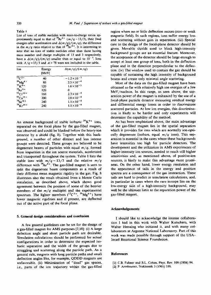
Table 1 List of ions of stable nuchdes with mass-tocharge ratios ap- proximately equal to that of 39Ar9+ (m/q - 13/3), their finaI energies after acceleration and A(m/ )/(m/q), the difference in the m/q ratio relative to that of 3% Ar9+. It is interesting to note that no ions of stable nuclides other than those having mass number and charge multiples of 13 and 3 respectively, have a A(m/q)/(m/q) smaller than or equal to 10m3. Ions with A/q = 13f3 and R > 78 were not included in the table.
An intense background of stable isobaric 39K9+ ions, separated on the focal plane by the gas-filled magnet, was observed and could be blocked before the heavy-ion detector by a shield (fig. 8). Together with this back- ground, a number of other distinct and less intense groups were detected. These groups are believed to be degenerate beams of particles with equal m/q, formed from impurities in the ion source materials, accelerated
and transported throughout the system. Table 1 lists the stable ions with m/q - 13/3 and the relative m/q
difference with 39Ar9+. The gas-filled magnet is seen to split the degenerate beam components as a result of their different mean magnetic rigidity in the gas. Fig. 8 illustrates also the result obtained from a Monte Carlo simulation, as described above, which shows good agreement between the position of some of the heavier members of the m/q multiplet and the experimental spectrum. The lighter members (13C3+, 26Mg6’) have lower magnetic rigidities and if present, are deflected out of the active part of the focal plane.
5. General design considerations and conch&on
A few genera1 guidelines can be set for the design of a gas-fiiled magnet for AMS purposes 17,181: (i) A large defection angle and short particle path are desirable. Simulation calculations should be performed for actual configurations in order to determine the expected iso- baric separation and the width of the groups due to straggling and scattering along the particle path. As a general rule, magnets with long particle paths and smalf deflection angles like, for example, QDDD magnets are unfavorable. (ii) Minirniz.ation of “dead” gas spaces, i.e., parts of the ion trajectory within the gas-filled
region where no or little deflection occurs (zero or weak magnetic field). In such regions, ions suffer energy loss and scattering without gain in separation. (iii) Special care to the design of the focal-plane detector should be given. Movable shields used to block high-intensity background groups are an essential feature. Moreover,
the acceptance of the detector should be large enough to accept at least one group of ions, both in the deflection plane and in the direction perpendicular to the defkzc- tion. {iv) The window used to contain the gas should be capable of sustaining the high intensity of background beams and create only minimal angle scattering.
Most of the data on the gas-filled magnet have been obtained so far with relatively high ion energies of a few MeV/nucleon. In this range, as seen above, the sep- aration power of the magnet is enhanced by the use of a focal-plane particle detector measuring residual energy and differential energy losses in order to discriminate
scattered particles. At low ion energies, this discrimina- tion is likely to be harder and only experiments will determine the capability of the method.
As has been emphasized above, the main advantage of the gas-filled magnet lies in the spatial separation which it provides for ions which are normally ion-opti-
cally degenerate (isobars, equal m/q ions). This sep- aration is essential in the cases where these backgrounds
have intensities too high for particle detectors. The development and the utilization in AMS experiments of higher-intensity ion sources, needed to reach still higher sensitivities and, as mentioned above, of positive-ion
sources, is likely to make this advantage more promi- nent. On the other hand, lower energy resolution and the appearance of tails in the energy and position spectra are a consequence of the gas interaction. These tails are hard to predict in simulation calculations, and, in particular in cases where the rare isotope lies on the low-energy side of a high-intensity background, may well be the ultimate limit to the separation power of the gas-filled magnet.
Acknowiedgements
I should like to acknowledge the intense collabora- tion I had in this work with Walter Kutschera, with Walter Henning who initiated it, and with many col- laborators at Argonne National Laboratory. Part of this work was made possible through support of the USA- Israel Binational Science Foundation.
References
[l] C.B. Fulmer and B.L. Cohen, Phys. Rev. 109 (1958) 94. 121 P. Armbruster, Nukleonik 3 (1961) 188.
M. Paul / Separation of isobars with a gas-filled magnet 321
131
I41
[51
I71
181
191
IlO1
H. Miyatake, T. Nomura, H. Kawakami, J. Tanaka, M.
Oyaizu, K. Morita, T. Shinozuka, H. Kudo. K. Sueki and
Y. Iwata. Nucl. Instr. and Meth. B26 (1987) 309.
A. Ghiorso, S. Yashita, ME. Leino, L. Frank, J. Kalnins,
P. Armbruster, J.-P. Dufour and P.K. Lemmertz, Nucl.
Instr. and Meth. A269 (1988) 192.
M. Paul, B.C. Glagola, W. Henning, J.G. Keller. W.
Kutschera, Z. Liu, K.E. Rehm, B. S&neck, R.H. Siems-
sen. Nucl. Instr. and Meth. A277 (1989) 418.
J.E. Spencer and H.A. Enge, Nucl. Instr. and Meth. 49
(1967) 181;
H.A. Enge, Nucl. Instr. and Meth. 162 (1979) 161.
P.W. Kubik, D. Elmore, T.K. Hemmick and W. Kutschera,