Journal of The Electrochemical Society OPEN ACCESS Separator Aging and Performance Degradation Caused by Battery Expansion: Cyclic Compression Test Simulation of Polypropylene Separator To cite this article: Zidan Yuan et al 2021 J. Electrochem. Soc. 168 030506 View the article online for updates and enhancements. This content was downloaded from IP address 65.21.228.167 on 28/10/2021 at 01:03
Transcript
Journal of The ElectrochemicalSociety
OPEN ACCESS
Separator Aging and Performance Degradation Caused by BatteryExpansion Cyclic Compression Test Simulation of PolypropyleneSeparatorTo cite this article Zidan Yuan et al 2021 J Electrochem Soc 168 030506
View the article online for updates and enhancements
This content was downloaded from IP address 6521228167 on 28102021 at 0103
Separator Aging and Performance Degradation Caused by BatteryExpansion Cyclic Compression Test Simulation of PolypropyleneSeparatorZidan Yuan Nanxiang Xue Jiayi Xie Ruijie Xuz and Caihong Leiz
Guangdong Provincial Key Laboratory of Functional Soft Condensed Matter Guangdong Provincial EngineeringLaboratory of Energy Storage Materials and Devices School of Materials and Energy Guangdong University ofTechnology Guangzhou 510006 Peoplersquos Republic of China
The structural changes of polyolefin separator during its service life greatly affect the working efficiency and safety of the lithium-ionbattery Researchers have known little about the relationship between the structural change of the separator and battery performance agingduring the service cycle Therefore we design one device that could simulate the separator environment in the battery to track the separatorstructure evolution during the periodic deformation process In this work the polypropylene separator is chosen and 1- 50- and 100- cyclecompression tests are carried out saturated with dimethly carbonate at different compression strain 75 125 and 15 The separatorsshow different degree of transparent wrinkles on the surface and higher impedance as the strain increases The ionic conductivity becomeslower The discharge capacity declines by 322 in DMC-125 and by 463 in DMC-15 The voltage platform of charge anddischarge in DMC-15 reduce obviously The damaged degree of lamellae skeleton around the transparent wrinkles in the separator isincreased with the cycle times and compression strain Along the transverse direction some pores are compressed and even closed leadingto the appearance of transparent wrinkles on the separator surface and resulting in the worse electrochemical performancecopy 2021 The Author(s) Published on behalf of The Electrochemical Society by IOP Publishing Limited This is an open accessarticle distributed under the terms of the Creative Commons Attribution 40 License (CC BY httpcreativecommonsorglicensesby40) which permits unrestricted reuse of the work in any medium provided the original work is properly cited [DOI 1011491945-7111abe724]
Manuscript submitted January 14 2021 revised manuscript received February 3 2021 Published March 2 2021
Supplementary material for this article is available online
With the development of the new energy industry the secondlybatteries such as Li-ion batteries have been widely used in our normallife especially in the Electric Vehicle(EV) and Hybrid ElectricVehicle(HEV) field1ndash6 However batteries aging is inevitable andhas become the research focus in the industrial and scientific field Thebatteries performance failure occurs during their service life Someworks attribute to the consumption of electrode materials duringcharge and discharge In addition the Li ions deposit on the surface ofcathode results in the reduction of discharging efficiency and capacityThe electrochemical inert substance produced during cycling alsoleads to the loss of capacity which is irreversible
Except for the electrodes the separator effect could not beneglected during the battery service life since the pore structure inthe separator directly influences the charge and discharge behaviorHowever due to the ldquoblack boxrdquo of assembled batteries the separatorchange during service could not be directly observed and character-ized Some researchers explored the separator property after over-charge by disassembling the overcharged batteries78 Zhang et al9
disassembled the batteries after 501003251200 times charge anddischarge cycles The mechanical strength of the separator wasreduced as the charge cycles increased The disassembling experimentcould not in situ reflect the separator change during service Someresearches simulated the separator application environments in thebatteries Batteries generate heat during work Studies have shown thatthe maximum internal temperature of the battery could reach 60 degCndash70 degC under 2 C charge and discharge rate10 By analyzing theAFM images of separator Chen11 found that the separator signifi-cantly closed pores at 90 degC cycled condition thus increasing the cellinternal impedance During battery service the electrolyte is always inthe battery Separators swell and soften in the electrolyte solvents12
because the electrolyte liquid penetrates into the separator pore andresults in the decrease of yield strength and Young modulus13 Inaddition to the temperature and electrolyte the stress effect is alsoinevitable During the battery assembling the drawing force exists forcell winding During the charge and discharge cycle the electrodeexpansion leads to the cycled compression loading to the separatorCompared with the drawing stress the cycled compression stress
brings more significant impact on the separator property Xu et al14
explained transport behavior of calendered separators Zhang et al15
established a punch device with different diameter hemisphericalpunch to study the failure modes of separator Zhu et al16ndash18 explainthat the deformation mechanism in three different directions (MDTDDD) of separator which can help us to explain our conclusion JohnCannarlla et al19 established one device for both compression andtensile stress-strain testing under solvent environment They built therelationship between the mechanical property and the loading speedLlya Avdeev et al2021 explored the influence of different loadingrate2223 and temperature on the separator performance under theelectrolyte environment The mechanical properties of the separatorwere dependent upon the strain temperature saturation in dimethlycarbonate (DMC) solvent and loading rate However up to now norelated works about the impact of cycled compression strain on theproperty of separators have been reported
Through the above disassembling and simulated experiment thepore size decrease or pore closure in the separator is observed Someresearchers believe that high temperature leads to the pore closure andsome believe that the electrode particles foist into the channel ofseparator Generally it is believed that the pore size decrease or poreclosure leads to the increase of separator internal resistance and thedecrease of ionic conductivity which influence the comprehensiveperformance of batteries such as cycle life and C-rate capability Asmentioned above the separator is under the complicated environmentincluding temperature electrolyte and cycled compression stress It isstill necessary to clarify the pore structure change under this compli-cated environment especially under the cycled compression stress
Nowadays the polyolefin separators in industrial application fallinto two broad categories24 The Wet-processed polyethylene (PE)separators are fabricated based on the thermal-induced phaseseparation mechanism The Dry-processed polypropylene (PP)separators are prepared using melt-stretching method Uniform poresexist among the fibrous crystals and separated lamellae Themicrostructure including pore lamellae and fibrous crystal existsin the PP separator As a key component the separator preventsphysical contact between the cathode and the anode and enablesionic transportation between the electrodes25ndash27 Therefore it isnecessary to clarify the microstructure change under the complicatedapplication environment of separator in the battery28zE-mail xu65786163com lch528gduteducn
Journal of The Electrochemical Society 2021 168 030506
During battery service battery expansion is an uncontrollablefactor The expansion degree could not be characterized accuratelyby disassembling the overloaded batteries When we disassemble theoverloaded batteries the electrode material particle may remain inthe separator pores directly influencing the characterization analysisof separator structure Obviously tracking the structural changes ofthe microporous separator during battery expansion is of greatsignificance to the research of battery safety In this work one setupwas firstly designed combining the punch test and swelling andsoftening of separators in electrolyte solvents This new experi-mental setup could punch the separators in the electrolyte environ-ment periodically Here the influence of cycled compression forceand electrolyte are included The coupled influence of cycledcompression force temperature and electrolyte will be reported inour next work The dimethly carbonate (DMC 99) was selected asthe simulated solvent of the electrolyte due to its liquid state at roomtemperature low toxicity and low price (Fig S1 (available online atstacksioporgJES168030506mmedia)) The surface morphologypore size and distributions of PP separator were characterized after100 times cycled compression The corresponding cycle life andC-rate capacity of button batteries assembled using Li metal anodeLiCoO2 cathode and cycled compressed separators were tested
Experimental
MaterialmdashThe PP separator (thickness 22 μm porosity 45)was provided by Shenzhen Senior Materials and TechnologyCompany China Liquid electrolyte (1 M LiPF6 in ECDMCDEC111 by volume) (LBC305-1 KJ GROUP) and lithium plates weresupplied by Shenzhen Kejing Star Technology Company ChinaLiCoO2 (the diameter is 12 mm and active material is 1349 mg) wassupplied by Jinghong Company China Dimethly carbonate (DMC99) was purchased from Tianjin ZhiYuan Reagent Co Ltd China
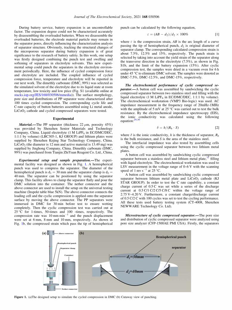
Experimental setup and sample preparationmdashThe experi-mental facility was designed as shown in Fig 1 A hemisphericalpunch was used to compress the separator The diameter of thehemispherical punch is d1 = 30 mm and the separator clamp is d2 =40 mm The separator can be positioned by using the separatorclamp This facility allows to clamp the separator flatly and pour theDMC solution into the container The nether connector and theabove connector are used to install the setup on the universal testingmachine (Inspekt table blue 5kN) The above connector connects theloading cell and the cyclic compression is applied onto the separatorsurface by moving the above connector The PP separators wereimmersed in DMC for 30 min before test to ensure wettingcompletely Then the cyclic compression test was carried out at25 degC for 1-times 50-times and 100 -times respectively Thecompression rate was 10 mm minminus1 and the punch displacementwere set at 6 mm 8 mm and 10 mm respectively As shown inFig 1b the compressed strain which pass the tip of hemispherical
punch can be calculated by the following equation
AB d d 100 12 2( ) [ ]e = - acute
where e is the compression strain AB is the arc length of a curvepassing the tip of hemispherical punch d2 is original diameter ofseparator clamp The corresponding calculated compression strain isabout 75 125 and 15 respectively The punch strain isselected by taking into account the yield strain of the separator alongthe transverse direction in the electrolyte (75) as shown in FigS1b and the limit of the battery expansion (15) After cycliccompression test the samples were dried in a vacuum oven for 6 hunder 45 degC to eliminate DMC solvent The samples were denoted asDMC-75 DMC-125 and DMC-15 respectively
The electrochemical performance of cyclic compressed se-paratormdashA button cell was assembled by sandwiching the cycliccompressed separator between two stainless steel and filling with theliquid electrolyte (1 M LiPF6 in ECDMCDEC 111 by volume)The electrochemical workstation (VMP3 Bio-logic) was used ACimpedance measurement in the frequency range of 20mHz-1MHzwith the amplitude of 5 mV at 25 degC was carried out to test the bulkresistance By the electrochemical impedance spectroscopy (EIS)the ionic conductivity was calculated using the followingequation2930
h R S 2b( middot ) [ ]d =
where δ is the ionic conductivity h is the thickness of separator Rb
is the bulk resistance and S is the area of the stainless steelThe interfacial impedance was also tested by assembling cells
using the cyclic compressed separator between two lithium metalplates
A button cell was assembled by sandwiching cyclic compressedseparator between a stainless steel and lithium metal plate31 fillingwith liquid electrolyte The electrochemical workstation was used toLSV measurement in the voltage range of 0ndash6 V with the scanningspeed of 1 mv sminus1 at 25 degC
A button cell was assembled by sandwiching cyclic compressedseparator between lithium metal plate and LiCoO2 cathode (KJSTAR GROUP) In order to test the C rate capability a constantcharge current of 05 C was set while a series of the dischargecurrent at 05 C1 C2 C5 C8 C within the voltage range of275 Vndash420 V Furthermore a constant chargedischarge currentof 05 C2 C with 100 cycles was set to test the cycling performanceAll these tests used battery testing system (CT-4008 ShenzhenNEWWARE Technology Co Ltd)
Microstructure of cyclic compressed separatormdashThe pore sizeand distribution of cyclic compressed separator were analyzed usingpore size analyzer (CFP-1500AE PMI USA) Firstly the separators
Figure 1 (a)The designed setup to simulate the cycled compression in DMC (b) Cutaway view of punching
Journal of The Electrochemical Society 2021 168 030506
were immersed into the solution with surface tension of 159 mN mminus1Secondly the samples were put into the sample room andpressurize the solution in the pore was able to overcome thecapillary action under pressure controlling the pressure increaseslowly by computer until the solution in the pore was empty Thenthe data of pore size and pore size distribution could be obtainedFurthermore the microstructure of separators were tested usingscanning electron microscope (SEM) (SN3400 HITACHI andSU8010 HITACHI Japan)
Results and Discussion
The surface photo of cyclic compressed separatormdashFigure 2gives the surface photo of initial separator and 100 times cycliccompressed separator under different compression strain Comparedwith the initial separator after displacement punch test the separatorappearance shows some transparent wrinkles along the machinedirection (MD) More wrinkles appear on the separators with thecompression strain increase The Dry-processed PP separator showshigh oriented porous structure exhibiting high strength and modulusalong MD whereas low strength along the transverse direction (TD)The cyclic compression test can be regarded as one kind of biaxialstretching along the separator surface The separator is easy to bedestroyed due to the low strength along TD leading to theappearance of transparent wrinkles along MD There are no apparent
macroscopic transparent wrinkles on the surface of cyclic com-pressed separator in DMC-75 whereas a lot of transparentwrinkles could be observed on the surface of cyclic compressedseparator in DMC-15 As mentioned above the yield point ofseparator along TD is 75 After the yield point the plasticmovement of molecule chains results in more deformation anddamage to the separator under the cyclic compression strain Thetransparent wrinkles almost appear around the edge of hemisphericalpunch but not at the center of hemispherical punch At the center ofhemispherical punch it mainly stretches along MD direction At theedge of hemispherical punch it mainly stretches along TD directionThe appearance position of transparent wrinkles is mainly within themaximum strain area
The electrochemial performance of cyclic compressed separa-torsmdashIn order to analyze the electrochemical performance of cycliccompressed separators the separators after 100 times cyclic com-pression test under different strain were assembled into buttonbatteries The bulk resistance interfacial resistance maximum stablevoltage C-rate capability and cycling performance were tested
Figure 3a gives the bulk resistance curves of separator withoutcyclic compression and 100 times cyclic compressed under differentstrain The Rb is the bulk resistance where the curve intersects theX-axis Then the ionic conductivity could be calculated based onEq 2 The results were listed in Table I The Rb values of PP
Figure 2 The surface appearance of initial separator and cyclic compressed separator(a) initial PP separator (b) 100 times cyclic compressed separator inDMC-75 DMC-125(c) and DMC-15(d)
Figure 3 (a) Bulk resistance (Rb) of different separators with stainless steelseparator-liquid electrolytestainless steel (b) interfacial resistance of differentseparators with Liseparator-liquid electrolyteLi
Table I Bulk resistance (Rb) ionic conductivity and interfacial impedance of different separators
Sample Rb(Ω) Ionic Conductivity (S cmminus1) Interfacial Impedance (Ω)
PP separator without cyclic compression 078 137 times 10minus3 66100 times compressed in DMC-75 079 135 times 10minus3 74100 times compressed in DMC-125 090 119 times 10minus3 92100 times compressed in DMC-15 118 897 times 10minus4 127
Journal of The Electrochemical Society 2021 168 030506
separators after cyclic compression tests are higher than that withoutcyclic compression leading to lower ionic conductivity Especiallythe ionic conductivity between PP separator without cyclic compres-sion and 100 times cyclic compressed in DMC-15 is differentabout an order of magnitude The ionic conductivity decreases withthe cyclic compression strain increasing The higher Rb and lowerionic conductivity demonstrate that the lithium ions shuttles throughthe separator become difficult
Figure 3b gives the AC impedance curves of separators withoutcyclic compression and 100 times cyclic compressed The semicirclein intermediate and high frequency region represents ionic conduc-tion about charge transfer between separator and electrolyte Thelow frequency region represents diffusion of lithium ions in activesubstance The difference between the value of the X axis ofinflection point of semicircle curve in low frequency and the valueof the intersect X axis of semicircle curve in high frequencyrepresents the interfacial impedance As shown in Table I the PP
separator without cyclic compression has a smallest interfacialimpedance about 66 Ω whereas the interfacial impedance of PPseparators after punch test are all larger The values are 74 Ω 92 Ωand 127 Ω for separators cyclic compressed in DMC-75 DMC-125 and DMC-15 respectively Especially the interfacialimpedance of DMC-15 is twice as much as that without cycliccompression Generally the interfacial impedance is used tocharacterize whether the separator and electrode contact well Thesmaller the interfacial impedance is the better the contact Thecyclic compression test results in some damage to the separatorsurface and some unrecoverable deformation The surface of PPseparator becomes more wrinkled with the compression strainincreasing The wrinkles show impact on the contact between theseparator and lithium plates The separators exhibit poor contactwith the lithium plates
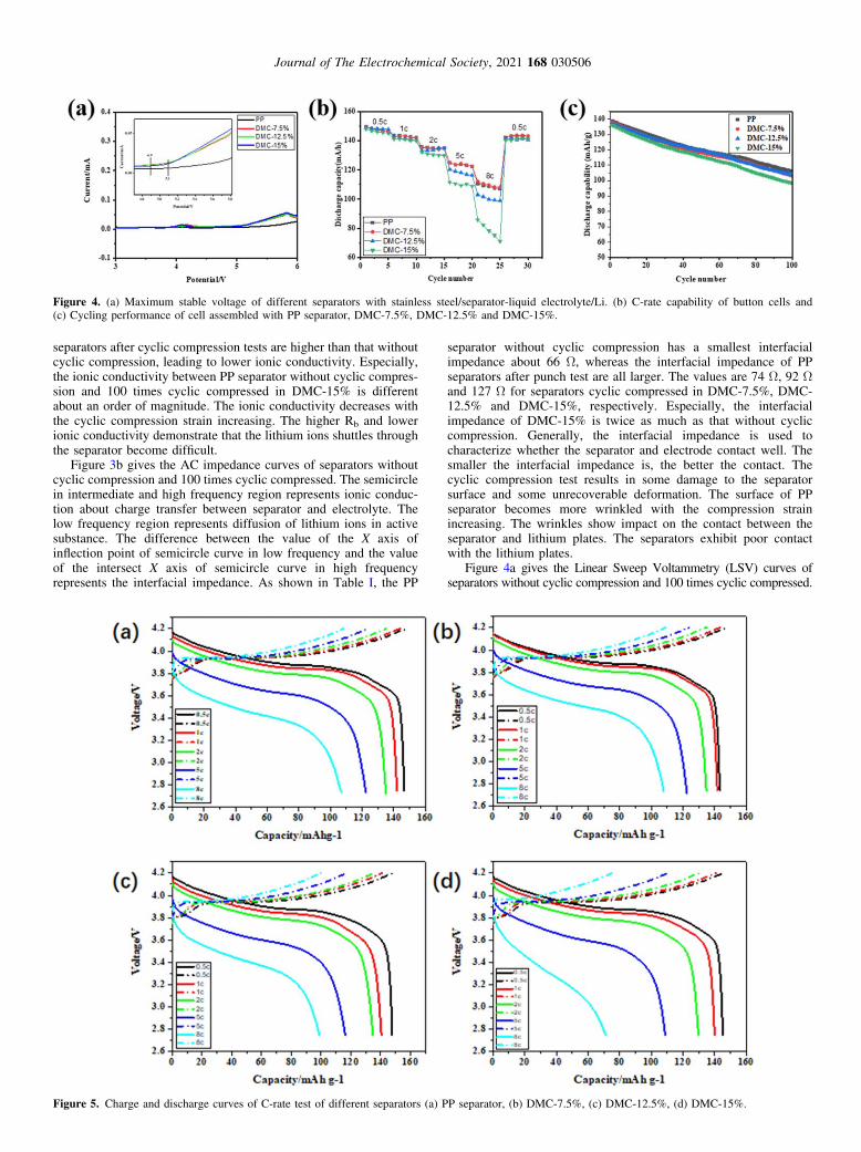
Figure 4a gives the Linear Sweep Voltammetry (LSV) curves ofseparators without cyclic compression and 100 times cyclic compressed
Figure 4 (a) Maximum stable voltage of different separators with stainless steelseparator-liquid electrolyteLi (b) C-rate capability of button cells and(c) Cycling performance of cell assembled with PP separator DMC-75 DMC-125 and DMC-15
Figure 5 Charge and discharge curves of C-rate test of different separators (a) PP separator (b) DMC-75 (c) DMC-125 (d) DMC-15
Journal of The Electrochemical Society 2021 168 030506
The maximum stable voltage could be characterized through LSV test inthe voltage range of 0ndash6 V and scan speed of 1 mV sminus1 As shown inFig 4a the maximum stable voltage of the PP separator without cycliccompression is 51 V and the separators after cyclic compression testare decreased to 49 V Exceed the maximum stable voltage thepolarization degree of separators after cyclic compression test is largerthan that without cyclic compression Whatrsquos more as shown in thepartial enlarged drawing in Fig 4a the slope of polarization curveslightly increased gradually with the compression strain increasing AllLSV curves show oxidation peak near X = 41 V This is the oxidationof lithium plates
The discharge capacity of button cells within 05 Cndash8 C areshown in Fig 4b The C-rate curves of DMC-75 and PP separatorwithout cyclic compression coincide nearly The 75 strain doesnot influence the C-rate performance or the influence is too small totested Before the 2 C rate the curve of DMC-125 and PP
separator without cyclic compression have no distinct differenceIn the rate of 5 C the discharge capacity declines by 204 In therate of 8 C the discharge capacity declines by 322 Furthermorethe results suggest that in DMC-15 the discharge capacity declinebegins at 2 C the discharge capacity declines by 107 in the rate of2 C declines by 248 in the rate of 5 C and declines by 463 inthe rate of 8 C In addition cycling 5 times in the rate of 8 C thedischarge capacity shows significant drop After 8 C for 5 cyclesthe discharge capacity declines by 52 which exceeds the half ofthe initial discharge capacity
In Fig 5 the full lines represent discharge curves and the dashedlines are charge curves Charge lines and discharge lines of DMC-75 are similar to the separator without cyclic compressionStarting from the rate of 2 C the platform of charge and dischargeof DMC-15 reduces obviously Especially in the rate of 8 C thevoltage of cell sharp declines as the charge and discharge capacity
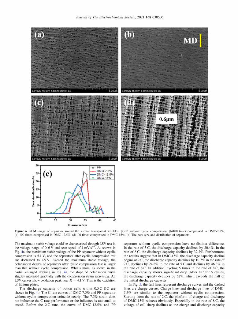
Figure 6 SEM image of separator around the surface transparent wrinkles (a)PP without cyclic compression (b)100 times compressed in DMC-75(c) 100 times compressed in DMC-125 (d)100 times compressed in DMC-15 (e) The pore size and distribution of separators
Journal of The Electrochemical Society 2021 168 030506
increase Starting from the rate of 5 C the voltage platform of chargeand discharge of DMC-125 begins to reduce and the platformshrinks to a minimum in the rate of 8 C The poor contact betweenseparators and electrode leads to the interfacial impedance increaseWhatrsquos more the ionic conductivity decreasing may impact on theC-rate capability
The cycle life of the batteries is shown in Fig 4c The firstdischarge capacity of the samples are coincided After 100 cycles
the discharge capacity of batteries with DMC-75 and DMC-125 have a slight drop but not obvious but the cycle life of DMC-15 after 100 cycle have clear downward trend in comparison to theoriginal one The discharge capability of the battery with DMC-15is 723 of its initial capacity compared to 764 of the original PPseparator after 100 cycles Under 2 C rate the discharge capacity ofDMC-15 begins to decline in agreement with the cycle life test Insummary the cycle capacities of DMC-75 and DMC-125 drop
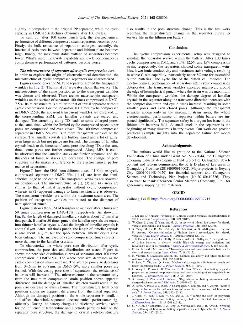
Figure 7 SEM images of different position of 100 times compressed separator in DMC-15 (1)ndash(4) from the hemispherical edge to the center
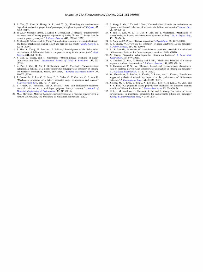
Figure 8 SEM images of separator around the transparent wrinkles (a) 1 times compressed in DMC-15 (b) 50 times compressed in DMC-15
Journal of The Electrochemical Society 2021 168 030506
slightly in comparison to the original PP separator while the cyclecapacity in DMC-15 declines obviously after 100 cycles
To sum up after 100 times punch test the electrochemicalperformance of different compressed strain separators becomes poorFirstly the bulk resistance of separators enlarges secondly theinterfacial resistance between separator and lithium plate becomeslarge thirdly the maximum stable voltage of separators becomeslower Whatrsquos more the C-rate capability and cycle performance acomprehensive performance of batteries become worse
The microstructure of separator after cyclic compression testmdashIn order to explore the origin of electrochemical deterioration themicrostructure of cyclic compressed separators are characterized
Figures 6andash6d gives the SEM of separator around the transparentwrinkles (in Fig 2) The initial PP separator shows flat surface Themicrostructure of the same position as to the transparent wrinkleswas chosen and observed There are no macroscopic transparentwrinkles on the surface of separator 100 times compressed in DMC-75 Its microstructure is similar to that of initial separator withoutcyclic compression For the separators 100 times cyclic compressedin DMC-125 the apparent transparent wrinkles are observed Inthe corresponding SEM the lamellar crystals are teared anddamaged The stretching along TD leads to some enlarged poresat the same time within the limited cyclic compressed space otherpores are compressed and even closed The 100 times compressedseparator in DMC-15 results in more transparent wrinkles on thesurface The lamellar crystals are further teared and a lot of gullyeven large notch but not pierce are formed The damage of lamellaecrystals leads to the increase of some pore size along TD at the sametime some pores are further compressed Along MD it couldbe observed that the lamellae stacks are further separated and thethickness of lamellae stacks are decreased The change of porestructure maybe makes a difference to the electrochemical perfor-mance of separators
Figure 7 shows the SEM from different areas of 100 times cycliccompressed separator in DMC-15 (1)ndash(4) are from the hemi-spherical edge to the center The transparent wrinkles are observedon position (2) The microstructure of (1) (3) and (4) areas aresimilar to that of initial separator without cyclic compressionwhereas in (2) apparent damage to lamellae structure is observedThe transparent wrinkles are within the maximum strain area Theposition of transparent wrinkles are related to the diameter ofhemispherical punch
Figure 8 shows the SEM of transparent wrinkles after 1 times and50 times compression in DMC-15 respectively As shown inFig 8a the length of damaged lamellar crystals is about 17 μm afterfirst punch But after 50 times punch the lamellar crystals are tearedinto thinner lamellar crystals And the length of lamellar crystals isabout 06 μm After 100 times punch the length of lamellar crystalsis also about 06 μm but the space between lamellar crystals hasbeen enlarged The increase of cyclic compression times results inmore damage to the lamellar crystals
To characterize the whole pore size distribution after cycliccompression the pore size and distribution are tested Figure 6eshows the pore size distribution curves of separator after 100 timescompression in DMC-15 The whole pore size decreases as thecyclic compression strain increase The average pore size decreasesfrom 346 nm to 308 nm In DMC-15 more smaller pores areformed With decreasing pore size of separators the resistance ofbatteries will increase32 The microstructure in the separator onlyfrom the maximum compression strain position shows apparentdifference and the damage of lamellae skeleton would result in thepore size decrease or even closure The microstructure from otherpositions shows no apparent difference from the initial separatorAlthough the damaged position in the whole separator is small itstill affects the whole separator electrochemical performance sig-nificantly During the battery charge and discharge service exceptfor the influence of temperature and electrode particles foist on theseparator pore structure the damage of crystal skeleton structure
also results in the pore structure change This is the first workreporting the microstructure change in the separator during itsservice life in the lithium ion battery
Conclusions
The cyclic compression experimental setup was designed tosimulate the separator service within the battery After 100 timescyclic compression in DMC and 75 125 and 15 compressionstrain respectively the separators showed some transparent wrin-kles lower ionic conductivity and maximum stable voltage resultingin worse C-rate capability particularly under 8C-rate for assembledbutton batteries The cycle life of the button cell reduced Theelectrochemical performance of separators after cyclic compressiondeteriorates The transparent wrinkles appeared intensively aroundthe edge of hemispherical punch where the strain was the maximumWithin the transparent wrinkles the damage degree of lamellarcrystals in the separator along the transverse direction increased withthe compression strain and cyclic times increase resulting in somesmaller pores and even closed pores Although the transparentwrinkles appear only in the maximum strain areas the wholeelectrochemical performance of separator within battery are im-pacted significantly The separator safety is a urgent hot issue in thelithium ion batteries field A small crack in the separator is thebeginning of many disastrous battery events Our work can providepractical example insights into the separator failure for modeldevelopment
Acknowledgments
The authors would like to gratitude to the National ScienceFoundation of China under Grant No 51773044 the Guangzhouemerging industry development fund project of Guangzhou devel-opment and reform commission the R amp D plan of key areas inGuangdong Province (2019B090914002) Major projects in JieyangCity (200109114840429) for financial support and GuangzhouScience and Technology Plan Project (No20180410326) Theyalso want to thank Shenzhen Senior Materials Company Ltd forgenerously supplying raw materials
ORCID
Caihong Lei httpsorcidorg0000-0002-3660-7715
References
1 J Du and D Ouyang ldquoProgress of Chinese electric vehicles industrialization in2015 a reviewrdquo Appl Energy 188 529 (2017)
2 W Chen J Liang Z Yang and G Li ldquoA review of lithium-ion battery for electricvehicle applications and beyondrdquo Energy Procedia 158 4363 (2019)
3 X Zeng M Li D Abd El-Hady W Alshitari A S Al-Bogami J Lu andK Amine ldquoCommercialization of lithium battery technologies for electricvehiclesrdquo Adv Energy Mater 9 19001611900161 (2019)
4 J B Dunn L Gaines J C Kelly C James and K G Gallagher ldquoThe significanceof Li-ion batteries in electric vehicle life-cycle energy and emissions andrecyclingrsquos role in its reductionrdquo Energy amp Environmental ence 8 158 (2014)
5 D Larcher and J M Tarascon ldquoTowards greener and more sustainable batteries forelectrical energy storagerdquo Nat Chem 7 19 (2015)
6 H Vikstrm S Davidsson and M Hk ldquoLithium availability and future productionoutlooksrdquo Appl Energy 110 252 (2013)
7 H Luo Y Xia and Q Zhou ldquoMechanical damage in a lithium-ion pouch cellunder indentation loadsrdquo J Power Sources 357 61 (2017)
8 E Wang H P Wu C H Chiu and P H Chou ldquoThe effect of battery separatorproperties on thermal ramp overcharge and short circuiting of rechargeable li-ionbatteriesrdquo J Electrochem Soc 166 A125 (2019)
9 X Zhang J Zhu and E Sahraei ldquoDegradation of battery separators underchargendashdischarge cyclesrdquo RSC Adv 7 56099 (2017)
10 A Perea A Paolella J Dube D Champagne A Mauger and K Zaghib ldquoState ofcharge influence on thermal reactions and abuse tests in commercial lithium-ioncellsrdquo J Power Sources 399 392 (2018)
11 J Chen Y Yan T Sun Y Qi and X Li ldquoProbing the roles of polymericseparators in lithium-ion battery capacity fade at elevated temperaturesrdquoJ Electrochem Soc 161 A1241 (2014)
12 G Y Gor J Cannarella C Z Leng A Vishnyakov and C B Arnold ldquoSwellingand softening of lithium-ion battery separators in electrolyte solventsrdquo J PowerSources 294 167 (2015)
Journal of The Electrochemical Society 2021 168 030506
13 S Yan X Xiao X Huang X Li and Y Qi ldquoUnveiling the environment-dependent mechanical properties of porous polypropylene separatorsrdquo Polymer 556282 (2014)
14 H Xu F Usseglio-Viretta S Kench S Cooper and D Finegan ldquoMicrostructurereconstruction of battery polymer separators by fusing 2D and 3D image data fortransport property analysisrdquo J Power Sources 480 229101 (2020)
15 X Zhang E Sahraei and K Wang ldquoLi-ion battery separators mechanical integrityand failure mechanisms leading to soft and hard internal shortsrdquo entific Reports 632578 (2016)
16 J Zhu X Zhang H Luo and E Sahraei ldquoInvestigation of the deformationmechanisms of lithium-ion battery components using in situ micro testsrdquo ApplEnergy 224 251 (2018)
17 J Zhu X Zhang and T Wierzbicki ldquoStretch-induced wrinkling of highlyorthotropic thin filmsrdquo International Journal of Solids amp Structures 139 238(2018)
18 Z Pan J Zhu H Xu T Sedlatschek and T Wierzbicki ldquoMicrostructuraldeformation patterns of a highly orthotropic polypropylene separator of lithium-ion batteries mechanism model and theoryrdquo Extreme Mechanics Letters 37100705 (2020)
19 J Cannarella X Liu C Z Leng P D Sinko G Y Gor and C B ArnoldldquoMechanical properties of a battery separator under compression and tensionrdquoJ Electrochem Soc 161 F3117 (2014)
20 I Avdeev M Martinsen and A Francis ldquoRate- and temperature-dependentmaterial behavior of a multilayer polymer battery separatorrdquo Journal ofMaterials Engineering amp Performance 23 315 (2014)
21 M J Martinsen Material behavior characterization of a thin film polymer used inlithium-ion batteries The University of Wisconsin-Milwaukee (2012)
22 L Wang S Yin J Xu and J Guan ldquoCoupled effect of strain rate and solvent ondynamic mechanical behaviors of separators in lithium ion batteriesrdquo Mater Des95 319 (2016)
23 J Zhu H Luo W Li T Gao Y Xia and T Wierzbicki ldquoMechanism ofstrengthening of battery resistance under dynamic loadingrdquo Int J Impact Eng131 78 (2019)
24 P Arora and Z Zhang ldquoBattery separatorsrdquo Cheminform 35 4419 (2004)25 S S Zhang ldquoA review on the separators of liquid electrolyte Li-ion batteriesrdquo
J Power Sources 164 351 (2007)26 R S Baldwin A review of state-of-the-art separator materials for advanced
lithium-based batteries for future aerospace missions NASA (2009)27 X Huang ldquoSeparator technologies for lithium-ion batteriesrdquo J Solid State
Electrochem 15 649 (2011)28 A Sheidaei X Xiao X Huang and J Hitt ldquoMechanical behavior of a battery
separator in electrolyte solutionsrdquo J Power Sources 196 8728 (2011)29 K Prasanna and C W Lee ldquoPhysical thermal and electrochemical characteriza-
tion of stretched polyethylene separators for application in lithium-ion batteriesrdquoJ Solid State Electrochem 17 1377 (2013)
30 W Haselrieder F Roeder A Kwade G Lenze and U Krewer ldquoSimulation-supported analysis of calendering impacts on the performance of lithium-ion-batteriesrdquo J Electrochem Soc 164 A1223 (2017)
31 J Song M H Ryou B Son J N Lee D J Lee Y M Lee J W Choi andJ K Park ldquoCo-polyimide-coated polyethylene separators for enhanced thermalstability of lithium ion batteriesrdquo Electrochim Acta 85 524 (2012)
32 H Lee M Yanilmaz O Toprakci K Fu and X Zhang ldquoA review of recentdevelopments in membrane separators for rechargeable lithium-ion batteriesrdquoEnergy amp Environmental ence 7 3857 (2014)
Journal of The Electrochemical Society 2021 168 030506
Separator Aging and Performance Degradation Caused by BatteryExpansion Cyclic Compression Test Simulation of PolypropyleneSeparatorZidan Yuan Nanxiang Xue Jiayi Xie Ruijie Xuz and Caihong Leiz
Guangdong Provincial Key Laboratory of Functional Soft Condensed Matter Guangdong Provincial EngineeringLaboratory of Energy Storage Materials and Devices School of Materials and Energy Guangdong University ofTechnology Guangzhou 510006 Peoplersquos Republic of China
The structural changes of polyolefin separator during its service life greatly affect the working efficiency and safety of the lithium-ionbattery Researchers have known little about the relationship between the structural change of the separator and battery performance agingduring the service cycle Therefore we design one device that could simulate the separator environment in the battery to track the separatorstructure evolution during the periodic deformation process In this work the polypropylene separator is chosen and 1- 50- and 100- cyclecompression tests are carried out saturated with dimethly carbonate at different compression strain 75 125 and 15 The separatorsshow different degree of transparent wrinkles on the surface and higher impedance as the strain increases The ionic conductivity becomeslower The discharge capacity declines by 322 in DMC-125 and by 463 in DMC-15 The voltage platform of charge anddischarge in DMC-15 reduce obviously The damaged degree of lamellae skeleton around the transparent wrinkles in the separator isincreased with the cycle times and compression strain Along the transverse direction some pores are compressed and even closed leadingto the appearance of transparent wrinkles on the separator surface and resulting in the worse electrochemical performancecopy 2021 The Author(s) Published on behalf of The Electrochemical Society by IOP Publishing Limited This is an open accessarticle distributed under the terms of the Creative Commons Attribution 40 License (CC BY httpcreativecommonsorglicensesby40) which permits unrestricted reuse of the work in any medium provided the original work is properly cited [DOI 1011491945-7111abe724]
Manuscript submitted January 14 2021 revised manuscript received February 3 2021 Published March 2 2021
Supplementary material for this article is available online
With the development of the new energy industry the secondlybatteries such as Li-ion batteries have been widely used in our normallife especially in the Electric Vehicle(EV) and Hybrid ElectricVehicle(HEV) field1ndash6 However batteries aging is inevitable andhas become the research focus in the industrial and scientific field Thebatteries performance failure occurs during their service life Someworks attribute to the consumption of electrode materials duringcharge and discharge In addition the Li ions deposit on the surface ofcathode results in the reduction of discharging efficiency and capacityThe electrochemical inert substance produced during cycling alsoleads to the loss of capacity which is irreversible
Except for the electrodes the separator effect could not beneglected during the battery service life since the pore structure inthe separator directly influences the charge and discharge behaviorHowever due to the ldquoblack boxrdquo of assembled batteries the separatorchange during service could not be directly observed and character-ized Some researchers explored the separator property after over-charge by disassembling the overcharged batteries78 Zhang et al9
disassembled the batteries after 501003251200 times charge anddischarge cycles The mechanical strength of the separator wasreduced as the charge cycles increased The disassembling experimentcould not in situ reflect the separator change during service Someresearches simulated the separator application environments in thebatteries Batteries generate heat during work Studies have shown thatthe maximum internal temperature of the battery could reach 60 degCndash70 degC under 2 C charge and discharge rate10 By analyzing theAFM images of separator Chen11 found that the separator signifi-cantly closed pores at 90 degC cycled condition thus increasing the cellinternal impedance During battery service the electrolyte is always inthe battery Separators swell and soften in the electrolyte solvents12
because the electrolyte liquid penetrates into the separator pore andresults in the decrease of yield strength and Young modulus13 Inaddition to the temperature and electrolyte the stress effect is alsoinevitable During the battery assembling the drawing force exists forcell winding During the charge and discharge cycle the electrodeexpansion leads to the cycled compression loading to the separatorCompared with the drawing stress the cycled compression stress
brings more significant impact on the separator property Xu et al14
explained transport behavior of calendered separators Zhang et al15
established a punch device with different diameter hemisphericalpunch to study the failure modes of separator Zhu et al16ndash18 explainthat the deformation mechanism in three different directions (MDTDDD) of separator which can help us to explain our conclusion JohnCannarlla et al19 established one device for both compression andtensile stress-strain testing under solvent environment They built therelationship between the mechanical property and the loading speedLlya Avdeev et al2021 explored the influence of different loadingrate2223 and temperature on the separator performance under theelectrolyte environment The mechanical properties of the separatorwere dependent upon the strain temperature saturation in dimethlycarbonate (DMC) solvent and loading rate However up to now norelated works about the impact of cycled compression strain on theproperty of separators have been reported
Through the above disassembling and simulated experiment thepore size decrease or pore closure in the separator is observed Someresearchers believe that high temperature leads to the pore closure andsome believe that the electrode particles foist into the channel ofseparator Generally it is believed that the pore size decrease or poreclosure leads to the increase of separator internal resistance and thedecrease of ionic conductivity which influence the comprehensiveperformance of batteries such as cycle life and C-rate capability Asmentioned above the separator is under the complicated environmentincluding temperature electrolyte and cycled compression stress It isstill necessary to clarify the pore structure change under this compli-cated environment especially under the cycled compression stress
Nowadays the polyolefin separators in industrial application fallinto two broad categories24 The Wet-processed polyethylene (PE)separators are fabricated based on the thermal-induced phaseseparation mechanism The Dry-processed polypropylene (PP)separators are prepared using melt-stretching method Uniform poresexist among the fibrous crystals and separated lamellae Themicrostructure including pore lamellae and fibrous crystal existsin the PP separator As a key component the separator preventsphysical contact between the cathode and the anode and enablesionic transportation between the electrodes25ndash27 Therefore it isnecessary to clarify the microstructure change under the complicatedapplication environment of separator in the battery28zE-mail xu65786163com lch528gduteducn
Journal of The Electrochemical Society 2021 168 030506
During battery service battery expansion is an uncontrollablefactor The expansion degree could not be characterized accuratelyby disassembling the overloaded batteries When we disassemble theoverloaded batteries the electrode material particle may remain inthe separator pores directly influencing the characterization analysisof separator structure Obviously tracking the structural changes ofthe microporous separator during battery expansion is of greatsignificance to the research of battery safety In this work one setupwas firstly designed combining the punch test and swelling andsoftening of separators in electrolyte solvents This new experi-mental setup could punch the separators in the electrolyte environ-ment periodically Here the influence of cycled compression forceand electrolyte are included The coupled influence of cycledcompression force temperature and electrolyte will be reported inour next work The dimethly carbonate (DMC 99) was selected asthe simulated solvent of the electrolyte due to its liquid state at roomtemperature low toxicity and low price (Fig S1 (available online atstacksioporgJES168030506mmedia)) The surface morphologypore size and distributions of PP separator were characterized after100 times cycled compression The corresponding cycle life andC-rate capacity of button batteries assembled using Li metal anodeLiCoO2 cathode and cycled compressed separators were tested
Experimental
MaterialmdashThe PP separator (thickness 22 μm porosity 45)was provided by Shenzhen Senior Materials and TechnologyCompany China Liquid electrolyte (1 M LiPF6 in ECDMCDEC111 by volume) (LBC305-1 KJ GROUP) and lithium plates weresupplied by Shenzhen Kejing Star Technology Company ChinaLiCoO2 (the diameter is 12 mm and active material is 1349 mg) wassupplied by Jinghong Company China Dimethly carbonate (DMC99) was purchased from Tianjin ZhiYuan Reagent Co Ltd China
Experimental setup and sample preparationmdashThe experi-mental facility was designed as shown in Fig 1 A hemisphericalpunch was used to compress the separator The diameter of thehemispherical punch is d1 = 30 mm and the separator clamp is d2 =40 mm The separator can be positioned by using the separatorclamp This facility allows to clamp the separator flatly and pour theDMC solution into the container The nether connector and theabove connector are used to install the setup on the universal testingmachine (Inspekt table blue 5kN) The above connector connects theloading cell and the cyclic compression is applied onto the separatorsurface by moving the above connector The PP separators wereimmersed in DMC for 30 min before test to ensure wettingcompletely Then the cyclic compression test was carried out at25 degC for 1-times 50-times and 100 -times respectively Thecompression rate was 10 mm minminus1 and the punch displacementwere set at 6 mm 8 mm and 10 mm respectively As shown inFig 1b the compressed strain which pass the tip of hemispherical
punch can be calculated by the following equation
AB d d 100 12 2( ) [ ]e = - acute
where e is the compression strain AB is the arc length of a curvepassing the tip of hemispherical punch d2 is original diameter ofseparator clamp The corresponding calculated compression strain isabout 75 125 and 15 respectively The punch strain isselected by taking into account the yield strain of the separator alongthe transverse direction in the electrolyte (75) as shown in FigS1b and the limit of the battery expansion (15) After cycliccompression test the samples were dried in a vacuum oven for 6 hunder 45 degC to eliminate DMC solvent The samples were denoted asDMC-75 DMC-125 and DMC-15 respectively
The electrochemical performance of cyclic compressed se-paratormdashA button cell was assembled by sandwiching the cycliccompressed separator between two stainless steel and filling with theliquid electrolyte (1 M LiPF6 in ECDMCDEC 111 by volume)The electrochemical workstation (VMP3 Bio-logic) was used ACimpedance measurement in the frequency range of 20mHz-1MHzwith the amplitude of 5 mV at 25 degC was carried out to test the bulkresistance By the electrochemical impedance spectroscopy (EIS)the ionic conductivity was calculated using the followingequation2930
h R S 2b( middot ) [ ]d =
where δ is the ionic conductivity h is the thickness of separator Rb
is the bulk resistance and S is the area of the stainless steelThe interfacial impedance was also tested by assembling cells
using the cyclic compressed separator between two lithium metalplates
A button cell was assembled by sandwiching cyclic compressedseparator between a stainless steel and lithium metal plate31 fillingwith liquid electrolyte The electrochemical workstation was used toLSV measurement in the voltage range of 0ndash6 V with the scanningspeed of 1 mv sminus1 at 25 degC
A button cell was assembled by sandwiching cyclic compressedseparator between lithium metal plate and LiCoO2 cathode (KJSTAR GROUP) In order to test the C rate capability a constantcharge current of 05 C was set while a series of the dischargecurrent at 05 C1 C2 C5 C8 C within the voltage range of275 Vndash420 V Furthermore a constant chargedischarge currentof 05 C2 C with 100 cycles was set to test the cycling performanceAll these tests used battery testing system (CT-4008 ShenzhenNEWWARE Technology Co Ltd)
Microstructure of cyclic compressed separatormdashThe pore sizeand distribution of cyclic compressed separator were analyzed usingpore size analyzer (CFP-1500AE PMI USA) Firstly the separators
Figure 1 (a)The designed setup to simulate the cycled compression in DMC (b) Cutaway view of punching
Journal of The Electrochemical Society 2021 168 030506
were immersed into the solution with surface tension of 159 mN mminus1Secondly the samples were put into the sample room andpressurize the solution in the pore was able to overcome thecapillary action under pressure controlling the pressure increaseslowly by computer until the solution in the pore was empty Thenthe data of pore size and pore size distribution could be obtainedFurthermore the microstructure of separators were tested usingscanning electron microscope (SEM) (SN3400 HITACHI andSU8010 HITACHI Japan)
Results and Discussion
The surface photo of cyclic compressed separatormdashFigure 2gives the surface photo of initial separator and 100 times cycliccompressed separator under different compression strain Comparedwith the initial separator after displacement punch test the separatorappearance shows some transparent wrinkles along the machinedirection (MD) More wrinkles appear on the separators with thecompression strain increase The Dry-processed PP separator showshigh oriented porous structure exhibiting high strength and modulusalong MD whereas low strength along the transverse direction (TD)The cyclic compression test can be regarded as one kind of biaxialstretching along the separator surface The separator is easy to bedestroyed due to the low strength along TD leading to theappearance of transparent wrinkles along MD There are no apparent
macroscopic transparent wrinkles on the surface of cyclic com-pressed separator in DMC-75 whereas a lot of transparentwrinkles could be observed on the surface of cyclic compressedseparator in DMC-15 As mentioned above the yield point ofseparator along TD is 75 After the yield point the plasticmovement of molecule chains results in more deformation anddamage to the separator under the cyclic compression strain Thetransparent wrinkles almost appear around the edge of hemisphericalpunch but not at the center of hemispherical punch At the center ofhemispherical punch it mainly stretches along MD direction At theedge of hemispherical punch it mainly stretches along TD directionThe appearance position of transparent wrinkles is mainly within themaximum strain area
The electrochemial performance of cyclic compressed separa-torsmdashIn order to analyze the electrochemical performance of cycliccompressed separators the separators after 100 times cyclic com-pression test under different strain were assembled into buttonbatteries The bulk resistance interfacial resistance maximum stablevoltage C-rate capability and cycling performance were tested
Figure 3a gives the bulk resistance curves of separator withoutcyclic compression and 100 times cyclic compressed under differentstrain The Rb is the bulk resistance where the curve intersects theX-axis Then the ionic conductivity could be calculated based onEq 2 The results were listed in Table I The Rb values of PP
Figure 2 The surface appearance of initial separator and cyclic compressed separator(a) initial PP separator (b) 100 times cyclic compressed separator inDMC-75 DMC-125(c) and DMC-15(d)
Figure 3 (a) Bulk resistance (Rb) of different separators with stainless steelseparator-liquid electrolytestainless steel (b) interfacial resistance of differentseparators with Liseparator-liquid electrolyteLi
Table I Bulk resistance (Rb) ionic conductivity and interfacial impedance of different separators
Sample Rb(Ω) Ionic Conductivity (S cmminus1) Interfacial Impedance (Ω)
PP separator without cyclic compression 078 137 times 10minus3 66100 times compressed in DMC-75 079 135 times 10minus3 74100 times compressed in DMC-125 090 119 times 10minus3 92100 times compressed in DMC-15 118 897 times 10minus4 127
Journal of The Electrochemical Society 2021 168 030506
separators after cyclic compression tests are higher than that withoutcyclic compression leading to lower ionic conductivity Especiallythe ionic conductivity between PP separator without cyclic compres-sion and 100 times cyclic compressed in DMC-15 is differentabout an order of magnitude The ionic conductivity decreases withthe cyclic compression strain increasing The higher Rb and lowerionic conductivity demonstrate that the lithium ions shuttles throughthe separator become difficult
Figure 3b gives the AC impedance curves of separators withoutcyclic compression and 100 times cyclic compressed The semicirclein intermediate and high frequency region represents ionic conduc-tion about charge transfer between separator and electrolyte Thelow frequency region represents diffusion of lithium ions in activesubstance The difference between the value of the X axis ofinflection point of semicircle curve in low frequency and the valueof the intersect X axis of semicircle curve in high frequencyrepresents the interfacial impedance As shown in Table I the PP
separator without cyclic compression has a smallest interfacialimpedance about 66 Ω whereas the interfacial impedance of PPseparators after punch test are all larger The values are 74 Ω 92 Ωand 127 Ω for separators cyclic compressed in DMC-75 DMC-125 and DMC-15 respectively Especially the interfacialimpedance of DMC-15 is twice as much as that without cycliccompression Generally the interfacial impedance is used tocharacterize whether the separator and electrode contact well Thesmaller the interfacial impedance is the better the contact Thecyclic compression test results in some damage to the separatorsurface and some unrecoverable deformation The surface of PPseparator becomes more wrinkled with the compression strainincreasing The wrinkles show impact on the contact between theseparator and lithium plates The separators exhibit poor contactwith the lithium plates
Figure 4a gives the Linear Sweep Voltammetry (LSV) curves ofseparators without cyclic compression and 100 times cyclic compressed
Figure 4 (a) Maximum stable voltage of different separators with stainless steelseparator-liquid electrolyteLi (b) C-rate capability of button cells and(c) Cycling performance of cell assembled with PP separator DMC-75 DMC-125 and DMC-15
Figure 5 Charge and discharge curves of C-rate test of different separators (a) PP separator (b) DMC-75 (c) DMC-125 (d) DMC-15
Journal of The Electrochemical Society 2021 168 030506
The maximum stable voltage could be characterized through LSV test inthe voltage range of 0ndash6 V and scan speed of 1 mV sminus1 As shown inFig 4a the maximum stable voltage of the PP separator without cycliccompression is 51 V and the separators after cyclic compression testare decreased to 49 V Exceed the maximum stable voltage thepolarization degree of separators after cyclic compression test is largerthan that without cyclic compression Whatrsquos more as shown in thepartial enlarged drawing in Fig 4a the slope of polarization curveslightly increased gradually with the compression strain increasing AllLSV curves show oxidation peak near X = 41 V This is the oxidationof lithium plates
The discharge capacity of button cells within 05 Cndash8 C areshown in Fig 4b The C-rate curves of DMC-75 and PP separatorwithout cyclic compression coincide nearly The 75 strain doesnot influence the C-rate performance or the influence is too small totested Before the 2 C rate the curve of DMC-125 and PP
separator without cyclic compression have no distinct differenceIn the rate of 5 C the discharge capacity declines by 204 In therate of 8 C the discharge capacity declines by 322 Furthermorethe results suggest that in DMC-15 the discharge capacity declinebegins at 2 C the discharge capacity declines by 107 in the rate of2 C declines by 248 in the rate of 5 C and declines by 463 inthe rate of 8 C In addition cycling 5 times in the rate of 8 C thedischarge capacity shows significant drop After 8 C for 5 cyclesthe discharge capacity declines by 52 which exceeds the half ofthe initial discharge capacity
In Fig 5 the full lines represent discharge curves and the dashedlines are charge curves Charge lines and discharge lines of DMC-75 are similar to the separator without cyclic compressionStarting from the rate of 2 C the platform of charge and dischargeof DMC-15 reduces obviously Especially in the rate of 8 C thevoltage of cell sharp declines as the charge and discharge capacity
Figure 6 SEM image of separator around the surface transparent wrinkles (a)PP without cyclic compression (b)100 times compressed in DMC-75(c) 100 times compressed in DMC-125 (d)100 times compressed in DMC-15 (e) The pore size and distribution of separators
Journal of The Electrochemical Society 2021 168 030506
increase Starting from the rate of 5 C the voltage platform of chargeand discharge of DMC-125 begins to reduce and the platformshrinks to a minimum in the rate of 8 C The poor contact betweenseparators and electrode leads to the interfacial impedance increaseWhatrsquos more the ionic conductivity decreasing may impact on theC-rate capability
The cycle life of the batteries is shown in Fig 4c The firstdischarge capacity of the samples are coincided After 100 cycles
the discharge capacity of batteries with DMC-75 and DMC-125 have a slight drop but not obvious but the cycle life of DMC-15 after 100 cycle have clear downward trend in comparison to theoriginal one The discharge capability of the battery with DMC-15is 723 of its initial capacity compared to 764 of the original PPseparator after 100 cycles Under 2 C rate the discharge capacity ofDMC-15 begins to decline in agreement with the cycle life test Insummary the cycle capacities of DMC-75 and DMC-125 drop
Figure 7 SEM images of different position of 100 times compressed separator in DMC-15 (1)ndash(4) from the hemispherical edge to the center
Figure 8 SEM images of separator around the transparent wrinkles (a) 1 times compressed in DMC-15 (b) 50 times compressed in DMC-15
Journal of The Electrochemical Society 2021 168 030506
slightly in comparison to the original PP separator while the cyclecapacity in DMC-15 declines obviously after 100 cycles
To sum up after 100 times punch test the electrochemicalperformance of different compressed strain separators becomes poorFirstly the bulk resistance of separators enlarges secondly theinterfacial resistance between separator and lithium plate becomeslarge thirdly the maximum stable voltage of separators becomeslower Whatrsquos more the C-rate capability and cycle performance acomprehensive performance of batteries become worse
The microstructure of separator after cyclic compression testmdashIn order to explore the origin of electrochemical deterioration themicrostructure of cyclic compressed separators are characterized
Figures 6andash6d gives the SEM of separator around the transparentwrinkles (in Fig 2) The initial PP separator shows flat surface Themicrostructure of the same position as to the transparent wrinkleswas chosen and observed There are no macroscopic transparentwrinkles on the surface of separator 100 times compressed in DMC-75 Its microstructure is similar to that of initial separator withoutcyclic compression For the separators 100 times cyclic compressedin DMC-125 the apparent transparent wrinkles are observed Inthe corresponding SEM the lamellar crystals are teared anddamaged The stretching along TD leads to some enlarged poresat the same time within the limited cyclic compressed space otherpores are compressed and even closed The 100 times compressedseparator in DMC-15 results in more transparent wrinkles on thesurface The lamellar crystals are further teared and a lot of gullyeven large notch but not pierce are formed The damage of lamellaecrystals leads to the increase of some pore size along TD at the sametime some pores are further compressed Along MD it couldbe observed that the lamellae stacks are further separated and thethickness of lamellae stacks are decreased The change of porestructure maybe makes a difference to the electrochemical perfor-mance of separators
Figure 7 shows the SEM from different areas of 100 times cycliccompressed separator in DMC-15 (1)ndash(4) are from the hemi-spherical edge to the center The transparent wrinkles are observedon position (2) The microstructure of (1) (3) and (4) areas aresimilar to that of initial separator without cyclic compressionwhereas in (2) apparent damage to lamellae structure is observedThe transparent wrinkles are within the maximum strain area Theposition of transparent wrinkles are related to the diameter ofhemispherical punch
Figure 8 shows the SEM of transparent wrinkles after 1 times and50 times compression in DMC-15 respectively As shown inFig 8a the length of damaged lamellar crystals is about 17 μm afterfirst punch But after 50 times punch the lamellar crystals are tearedinto thinner lamellar crystals And the length of lamellar crystals isabout 06 μm After 100 times punch the length of lamellar crystalsis also about 06 μm but the space between lamellar crystals hasbeen enlarged The increase of cyclic compression times results inmore damage to the lamellar crystals
To characterize the whole pore size distribution after cycliccompression the pore size and distribution are tested Figure 6eshows the pore size distribution curves of separator after 100 timescompression in DMC-15 The whole pore size decreases as thecyclic compression strain increase The average pore size decreasesfrom 346 nm to 308 nm In DMC-15 more smaller pores areformed With decreasing pore size of separators the resistance ofbatteries will increase32 The microstructure in the separator onlyfrom the maximum compression strain position shows apparentdifference and the damage of lamellae skeleton would result in thepore size decrease or even closure The microstructure from otherpositions shows no apparent difference from the initial separatorAlthough the damaged position in the whole separator is small itstill affects the whole separator electrochemical performance sig-nificantly During the battery charge and discharge service exceptfor the influence of temperature and electrode particles foist on theseparator pore structure the damage of crystal skeleton structure
also results in the pore structure change This is the first workreporting the microstructure change in the separator during itsservice life in the lithium ion battery
Conclusions
The cyclic compression experimental setup was designed tosimulate the separator service within the battery After 100 timescyclic compression in DMC and 75 125 and 15 compressionstrain respectively the separators showed some transparent wrin-kles lower ionic conductivity and maximum stable voltage resultingin worse C-rate capability particularly under 8C-rate for assembledbutton batteries The cycle life of the button cell reduced Theelectrochemical performance of separators after cyclic compressiondeteriorates The transparent wrinkles appeared intensively aroundthe edge of hemispherical punch where the strain was the maximumWithin the transparent wrinkles the damage degree of lamellarcrystals in the separator along the transverse direction increased withthe compression strain and cyclic times increase resulting in somesmaller pores and even closed pores Although the transparentwrinkles appear only in the maximum strain areas the wholeelectrochemical performance of separator within battery are im-pacted significantly The separator safety is a urgent hot issue in thelithium ion batteries field A small crack in the separator is thebeginning of many disastrous battery events Our work can providepractical example insights into the separator failure for modeldevelopment
Acknowledgments
The authors would like to gratitude to the National ScienceFoundation of China under Grant No 51773044 the Guangzhouemerging industry development fund project of Guangzhou devel-opment and reform commission the R amp D plan of key areas inGuangdong Province (2019B090914002) Major projects in JieyangCity (200109114840429) for financial support and GuangzhouScience and Technology Plan Project (No20180410326) Theyalso want to thank Shenzhen Senior Materials Company Ltd forgenerously supplying raw materials
ORCID
Caihong Lei httpsorcidorg0000-0002-3660-7715
References
1 J Du and D Ouyang ldquoProgress of Chinese electric vehicles industrialization in2015 a reviewrdquo Appl Energy 188 529 (2017)
2 W Chen J Liang Z Yang and G Li ldquoA review of lithium-ion battery for electricvehicle applications and beyondrdquo Energy Procedia 158 4363 (2019)
3 X Zeng M Li D Abd El-Hady W Alshitari A S Al-Bogami J Lu andK Amine ldquoCommercialization of lithium battery technologies for electricvehiclesrdquo Adv Energy Mater 9 19001611900161 (2019)
4 J B Dunn L Gaines J C Kelly C James and K G Gallagher ldquoThe significanceof Li-ion batteries in electric vehicle life-cycle energy and emissions andrecyclingrsquos role in its reductionrdquo Energy amp Environmental ence 8 158 (2014)
5 D Larcher and J M Tarascon ldquoTowards greener and more sustainable batteries forelectrical energy storagerdquo Nat Chem 7 19 (2015)
6 H Vikstrm S Davidsson and M Hk ldquoLithium availability and future productionoutlooksrdquo Appl Energy 110 252 (2013)
7 H Luo Y Xia and Q Zhou ldquoMechanical damage in a lithium-ion pouch cellunder indentation loadsrdquo J Power Sources 357 61 (2017)
8 E Wang H P Wu C H Chiu and P H Chou ldquoThe effect of battery separatorproperties on thermal ramp overcharge and short circuiting of rechargeable li-ionbatteriesrdquo J Electrochem Soc 166 A125 (2019)
9 X Zhang J Zhu and E Sahraei ldquoDegradation of battery separators underchargendashdischarge cyclesrdquo RSC Adv 7 56099 (2017)
10 A Perea A Paolella J Dube D Champagne A Mauger and K Zaghib ldquoState ofcharge influence on thermal reactions and abuse tests in commercial lithium-ioncellsrdquo J Power Sources 399 392 (2018)
11 J Chen Y Yan T Sun Y Qi and X Li ldquoProbing the roles of polymericseparators in lithium-ion battery capacity fade at elevated temperaturesrdquoJ Electrochem Soc 161 A1241 (2014)
12 G Y Gor J Cannarella C Z Leng A Vishnyakov and C B Arnold ldquoSwellingand softening of lithium-ion battery separators in electrolyte solventsrdquo J PowerSources 294 167 (2015)
Journal of The Electrochemical Society 2021 168 030506
13 S Yan X Xiao X Huang X Li and Y Qi ldquoUnveiling the environment-dependent mechanical properties of porous polypropylene separatorsrdquo Polymer 556282 (2014)
14 H Xu F Usseglio-Viretta S Kench S Cooper and D Finegan ldquoMicrostructurereconstruction of battery polymer separators by fusing 2D and 3D image data fortransport property analysisrdquo J Power Sources 480 229101 (2020)
15 X Zhang E Sahraei and K Wang ldquoLi-ion battery separators mechanical integrityand failure mechanisms leading to soft and hard internal shortsrdquo entific Reports 632578 (2016)
16 J Zhu X Zhang H Luo and E Sahraei ldquoInvestigation of the deformationmechanisms of lithium-ion battery components using in situ micro testsrdquo ApplEnergy 224 251 (2018)
17 J Zhu X Zhang and T Wierzbicki ldquoStretch-induced wrinkling of highlyorthotropic thin filmsrdquo International Journal of Solids amp Structures 139 238(2018)
18 Z Pan J Zhu H Xu T Sedlatschek and T Wierzbicki ldquoMicrostructuraldeformation patterns of a highly orthotropic polypropylene separator of lithium-ion batteries mechanism model and theoryrdquo Extreme Mechanics Letters 37100705 (2020)
19 J Cannarella X Liu C Z Leng P D Sinko G Y Gor and C B ArnoldldquoMechanical properties of a battery separator under compression and tensionrdquoJ Electrochem Soc 161 F3117 (2014)
20 I Avdeev M Martinsen and A Francis ldquoRate- and temperature-dependentmaterial behavior of a multilayer polymer battery separatorrdquo Journal ofMaterials Engineering amp Performance 23 315 (2014)
21 M J Martinsen Material behavior characterization of a thin film polymer used inlithium-ion batteries The University of Wisconsin-Milwaukee (2012)
22 L Wang S Yin J Xu and J Guan ldquoCoupled effect of strain rate and solvent ondynamic mechanical behaviors of separators in lithium ion batteriesrdquo Mater Des95 319 (2016)
23 J Zhu H Luo W Li T Gao Y Xia and T Wierzbicki ldquoMechanism ofstrengthening of battery resistance under dynamic loadingrdquo Int J Impact Eng131 78 (2019)
24 P Arora and Z Zhang ldquoBattery separatorsrdquo Cheminform 35 4419 (2004)25 S S Zhang ldquoA review on the separators of liquid electrolyte Li-ion batteriesrdquo
J Power Sources 164 351 (2007)26 R S Baldwin A review of state-of-the-art separator materials for advanced
lithium-based batteries for future aerospace missions NASA (2009)27 X Huang ldquoSeparator technologies for lithium-ion batteriesrdquo J Solid State
Electrochem 15 649 (2011)28 A Sheidaei X Xiao X Huang and J Hitt ldquoMechanical behavior of a battery
separator in electrolyte solutionsrdquo J Power Sources 196 8728 (2011)29 K Prasanna and C W Lee ldquoPhysical thermal and electrochemical characteriza-
tion of stretched polyethylene separators for application in lithium-ion batteriesrdquoJ Solid State Electrochem 17 1377 (2013)
30 W Haselrieder F Roeder A Kwade G Lenze and U Krewer ldquoSimulation-supported analysis of calendering impacts on the performance of lithium-ion-batteriesrdquo J Electrochem Soc 164 A1223 (2017)
31 J Song M H Ryou B Son J N Lee D J Lee Y M Lee J W Choi andJ K Park ldquoCo-polyimide-coated polyethylene separators for enhanced thermalstability of lithium ion batteriesrdquo Electrochim Acta 85 524 (2012)
32 H Lee M Yanilmaz O Toprakci K Fu and X Zhang ldquoA review of recentdevelopments in membrane separators for rechargeable lithium-ion batteriesrdquoEnergy amp Environmental ence 7 3857 (2014)
Journal of The Electrochemical Society 2021 168 030506