This British Standard, having been prepared under the direction of the Power Electrical Engineering Standards Policy Committee, was published under the authority of the Standards Board and comes into effect on15 April 1993
The following BSI references relate to the work on this standard:Committee reference PEL/104Special announcement in BSI News, July 1992
ISBN 0 580 21675 6
Committees responsible for this British Standard
The preparation of this British Standard was entrusted by the Power Electrical Engineering Standards Policy Committee (PEL/-) to Technical Committee PEL/104, upon which the following bodies were represented:
British Cable Makers’ ConfederationElectrical Installation Equipment Manufacturers’ AssociationElectricity AssociationInstitution of Electrical EngineersGAMBICA (BEAMA Ltd.)
PageCommittees responsible Inside front coverNational foreword iiForeword 2Text of HD 533 S1 5National annex NA (informative) Original IEC text amended by CENELEC common modifications Inside back coverNational annex NB (informative) Cross-references Inside back cover
This British Standard has been prepared under the direction of the Power Electrical Engineering Standards Policy Committee PEL/-. It implements Harmonization Document HD 533 S1:1991 which was published by the European Committee for Electrotechnical Standardization (CENELEC). It was derived by CENELEC from IEC 909:1988 Short circuit current calculations in three phase a.c. systems, published by the International Electrotechnical Commission (IEC).A British Standard does not purport to include all the necessary provisions of a contract. Users of British Standards are responsible for their correct application.
Compliance with a British Standard does not of itself confer immunity from legal obligations.
Summary of pagesThis document comprises a front cover, an inside front cover, pages i and ii, the HD title page, pages 2 to 86, an inside back cover and a back cover.This standard has been updated (see copyright date) and may have had amendments incorporated. This will be indicated in the amendment table on the inside front cover.
Descriptors: Calculation, short-circuit current, three-phase systems
English version
Short-circuit current calculation in three-phase a.c. systems
(IEC 909:1988, modified)
Calcul des courants de court-circuit dans les réseaux triphasés à courant alternatif (CEI 909:1988, modifiée)
Berechnung von Kurzschlußströmen in Drehstromnetzen (IEC 909, modifiziert)
This Harmonization Document was approved by CENELEC on 1990-03-05.CENELEC members are bound to comply with the CEN/CENELEC InternalRegulations which stipulate the conditions for implementation of thisHarmonization Document on a national level.Up-to-date lists and bibliographical references concerning such nationalimplementation may be obtained on application to the Central Secretariat orto any CENELEC member.This Harmonization Document exists in three official versions (English,French, German).CENELEC members are the national electrotechnical committees of Austria,Belgium, Denmark, Finland, France, Germany, Greece, Iceland, Ireland, Italy,Luxembourg, Netherlands, Norway, Portugal, Spain, Sweden, Switzerland andUnited Kingdom.
CENELEC
European Committee for Electrotechnical StandardizationComité Européen de Normalisation Electrotechnique
Europäisches Komitee für Elektrotechnische Normung
Central Secretariat: rue de Stassart 35, B-1050 Brussels
The CENELEC questionnaire procedure, performed for finding out whether or not the International Standard IEC 909:1988 could be accepted without textual changes, has shown that some CENELEC common modifications were necessary for the acceptance as Harmonization Document.The reference document, together with the common modifications prepared by the CENELEC Reporting Secretariat SR 73, was submitted to the CENELEC members for formal vote.The text of the draft was approved by all CENELEC members, with the exception of Austria, Finland and Norway, as HD 533 S1 on 5 March 1990.The following dates were fixed:
Contents
PageForeword 21 Scope 52 Object 53 Definitions 54 Symbols, subscripts and superscripts 84.1 Symbols 84.2 Subscripts 94.3 Superscripts 105 Calculation assumptions 116 Equivalent voltage source at the
short-circuit location 12Section 1. Systems with short-circuit currents having no a.c. component decay (far-from-generator short circuits)7 General 168 Short-circuit parameters 168.1 Balanced short circuit 168.2 Unbalanced short circuit 168.3 Short-circuit impedances 178.4 Conversion of impedances,
currents and voltages 239 Calculation of short-circuit currents 239.1 Calculation method for balanced
short circuits 239.2 Calculation method for line-to-line
and line-to-earth short circuits 279.3 The minimum short-circuit currents 30Section 2. Systems with short-circuit currents having decaying a.c. components (near-to-generator short circuits)10 General 3011 Short-circuit parameters 3111.1 General 3111.2 Balanced short circuit 3311.3 Unbalanced short circuit 3311.4 Equivalent voltage source at the
short-circuit location 3311.5 Short-circuit impedances 3311.6 Conversion of impedances,
currents and voltages 3712 Calculation of short-circuit currents 3712.1 General 3712.2 Calculation method for balanced
short circuits 37
— latest date of announcement of the HD at national level (doa) 1990-09-01
— latest date of publication of a new harmonized national standard (dop) 1991-11-01
— latest date of withdrawal of conflicting national standards (dow) 1991-11-01
loads and capacitors 5114.1 Parallel capacitors 5114.2 Series capacitors 51Appendix A (informative) Calculation of short-circuit currents 52Figure 1 — Short-circuit current of a far-from-generator short circuit (schematic diagram) 11Figure 2 — Characterization of short circuits and their currents. The direction of current arrows is chosen arbitrarily 13Figure 3 — Illustration for calculating the initial symmetrical short-circuit current in compliance with the procedure for the equivalent voltage source 14Figure 4 — Short-circuit impedance of a three-phase a.c. system at the short-circuit location F 15Figure 5 — Measuring of zero-sequence short-circuit impedances of electrical equipment (examples) 18Figure 6 — System diagram and equivalent circuit diagram for network feeders 19Figure 7 — Three-winding transformer (example) 22Figure 8 — Factor x for series circuits as a function of: a) ratio R/X; b) ratio X/R 24Figure 9 — System diagram illustrating a short circuit fed from several sources which are independent of one another. (In some cases the impedance between busbar B and the short-circuit location F may be neglected) 25Figure 10 — Illustration of the calculation of the initial symmetrical short-circuit current in a meshed network. The short-circuit current at the short-circuit location F is supplied by the feeder connection point Q throughtransformers T1 and T2 26
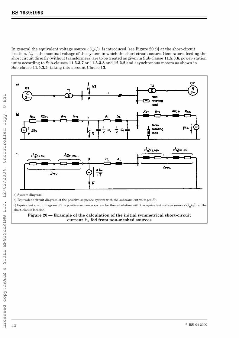
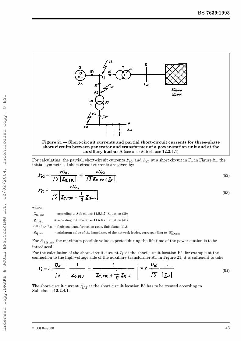
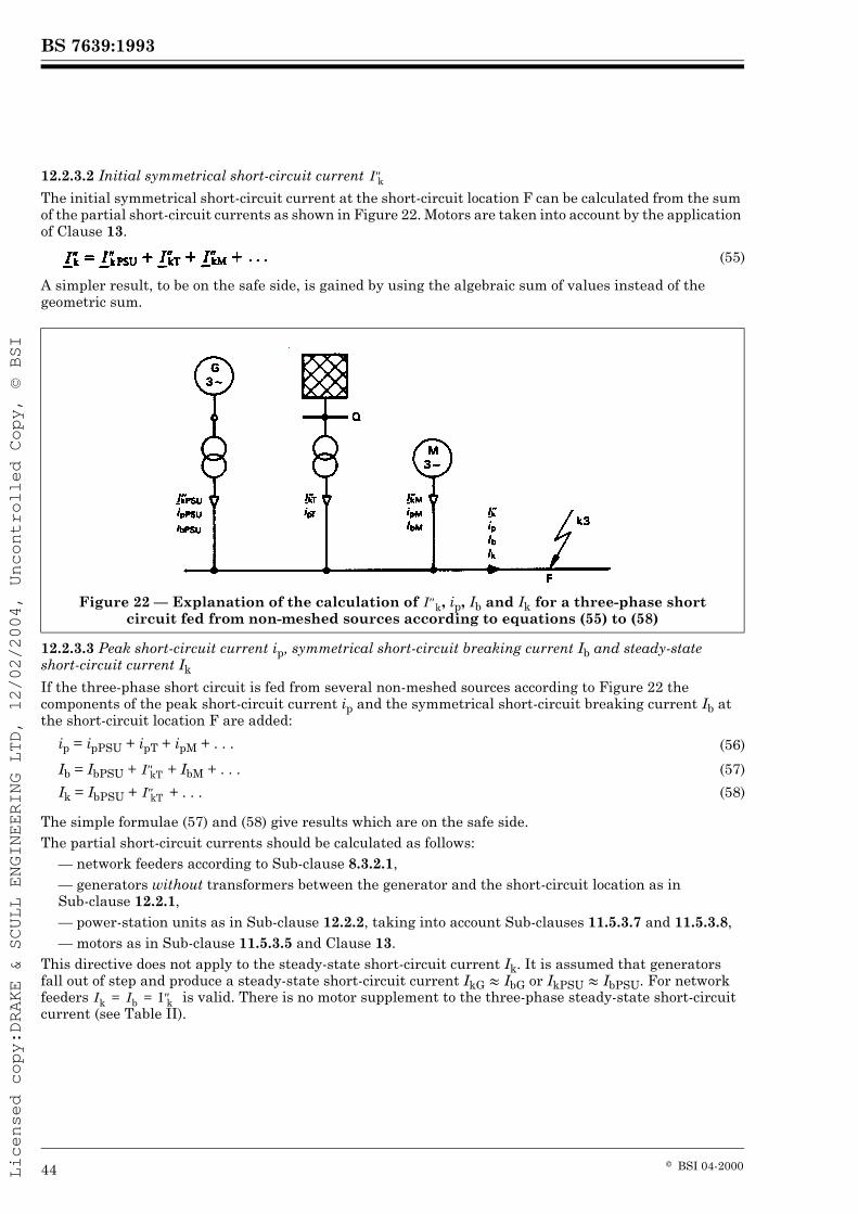
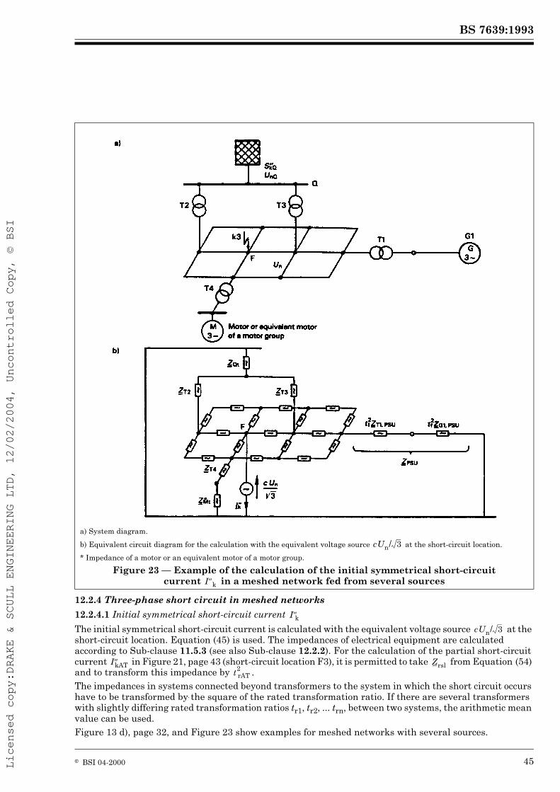
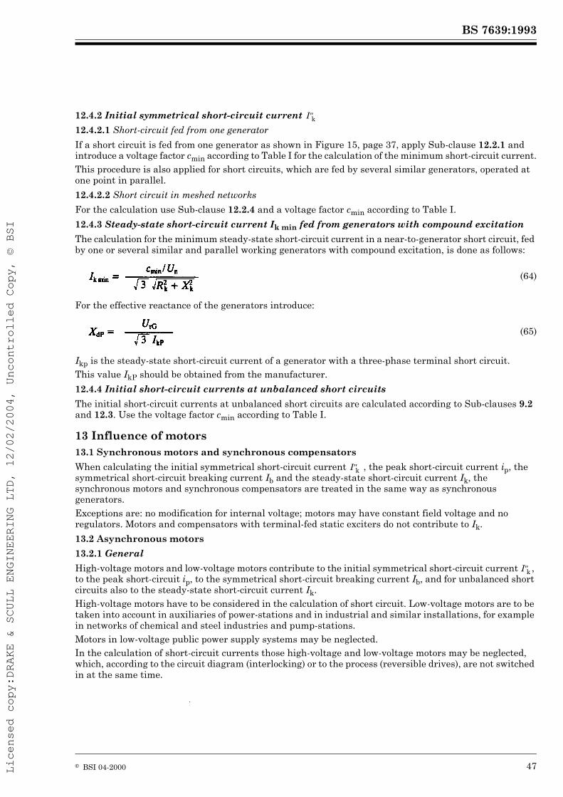
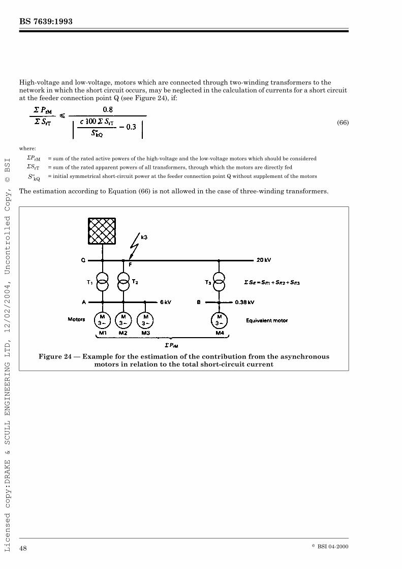
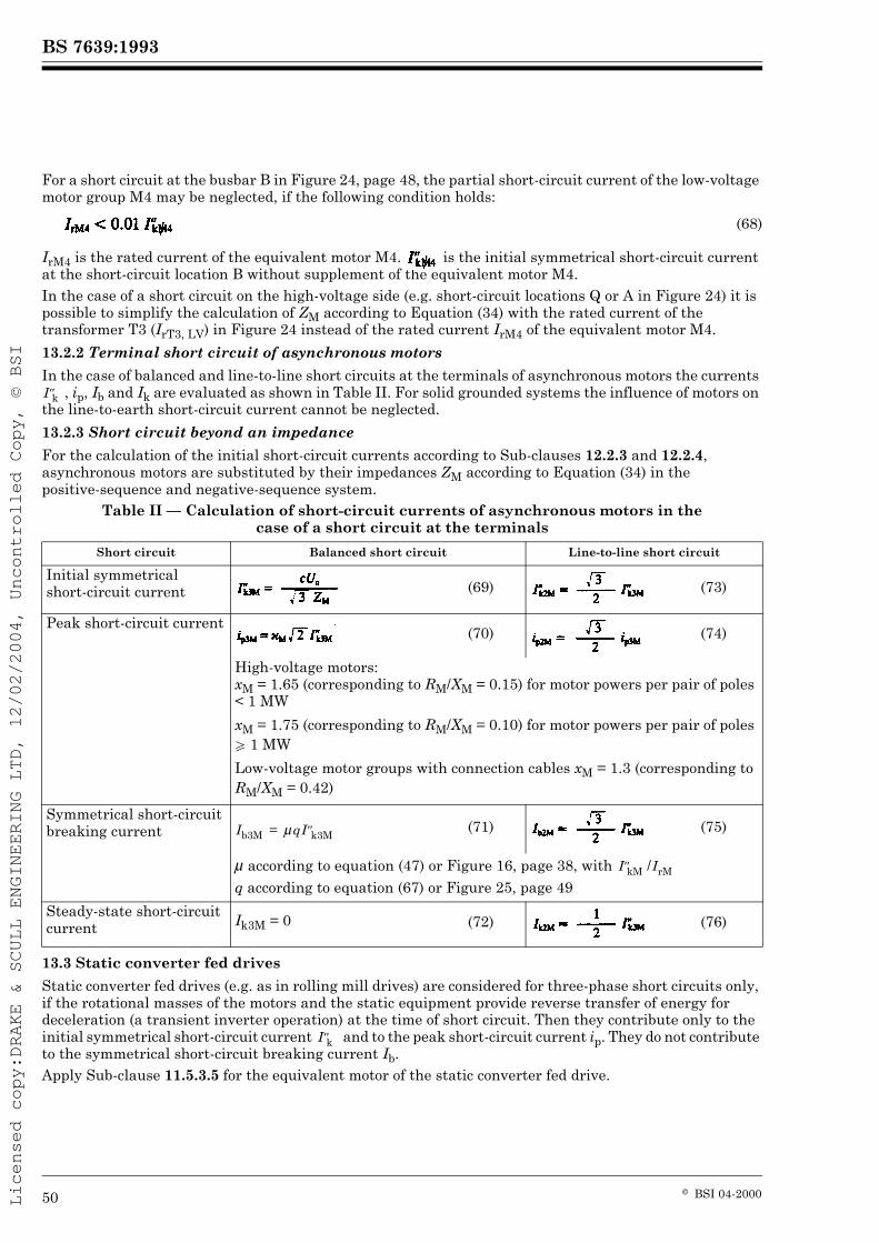
PageFigure 11 — Chart indicating the type of short-circuit giving the highest current 28Figure 12 — Short-circuit current of a near-to-generator short circuit (schematic diagram) 31Figure 13 — Various short-circuit source connections 32Figure 14 — Phasor diagram of a synchronous generator at rated conditions 35Figure 15 — Example for the calculation of the initial symmetrical short-circuit current for a short circuit fed directly from one generator 37Figure 16 — Factor È for the calculation of short-circuit breaking current Ib 38Figure 17 — Factors Æmax and Æmin for turbine generators 39Figure 18 — Factors Æmax and Æmin for salient-pole machines 40Figure 19 — Example of the calculation of the initial symmetrical short-circuit current fed from one power-station unit 41Figure 20 — Example of the calculation of the initial symmetrical short-circuit current fed from non-meshed sources 42Figure 21 — Short-circuit currents and partial short-circuit currents for three-phase short circuits between generator and transformer of a power-station unit and at the auxiliary busbar A 43Figure 22 — Explanation of the calculation of , ip, Ib and Ik for a three-phase short circuit fed from non-meshed sources according to equations (55) to (58) 44Figure 23 — Example of the calculation of the initial symmetrical short-circuit current in a meshed network fed from several sources 45Figure 24 — Example for the estimation of the contribution from the asynchronous motors in relation to the total short-circuit current 48Figure 25 — Factor q for the calculation of the symmetrical short-circuit breaking current of asynchronous motors 49
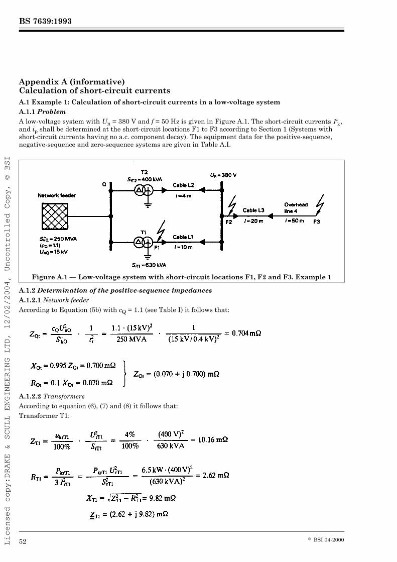
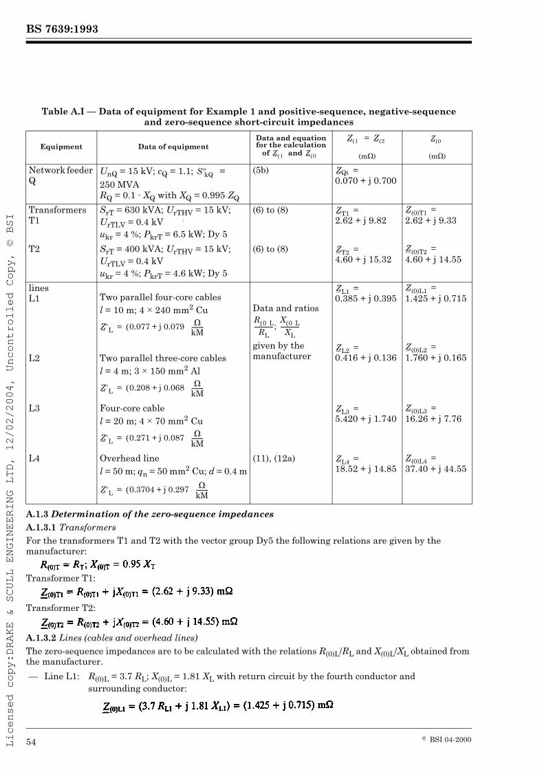
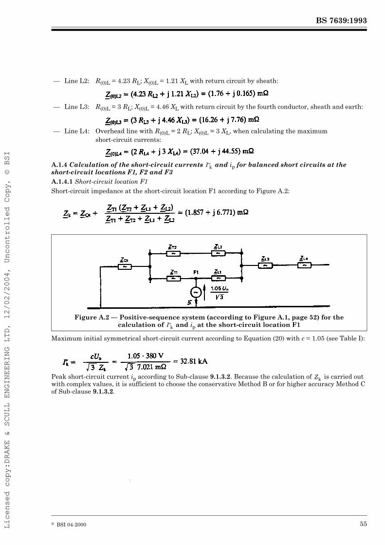
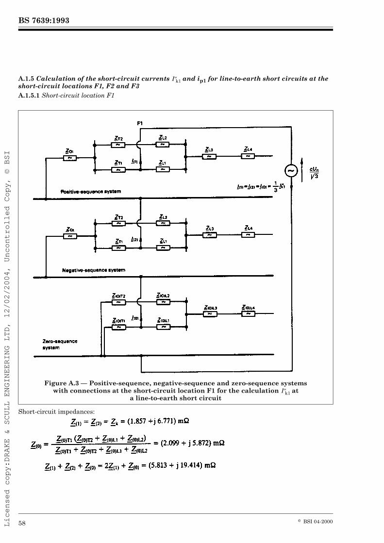
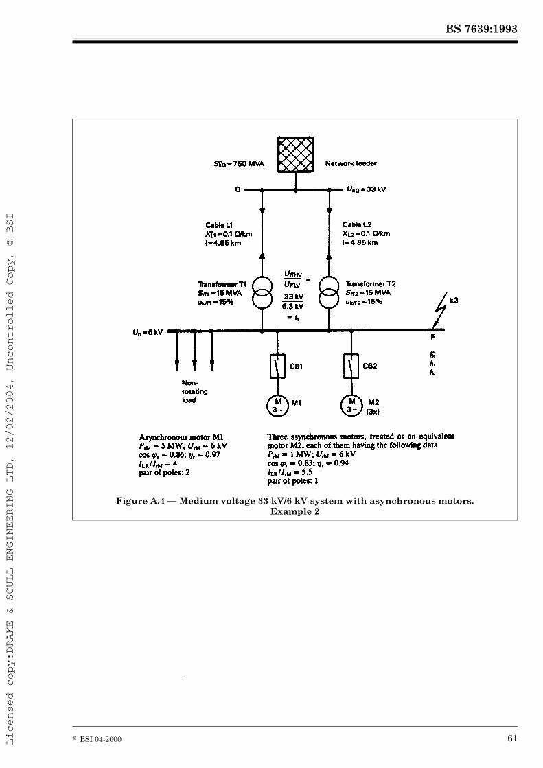
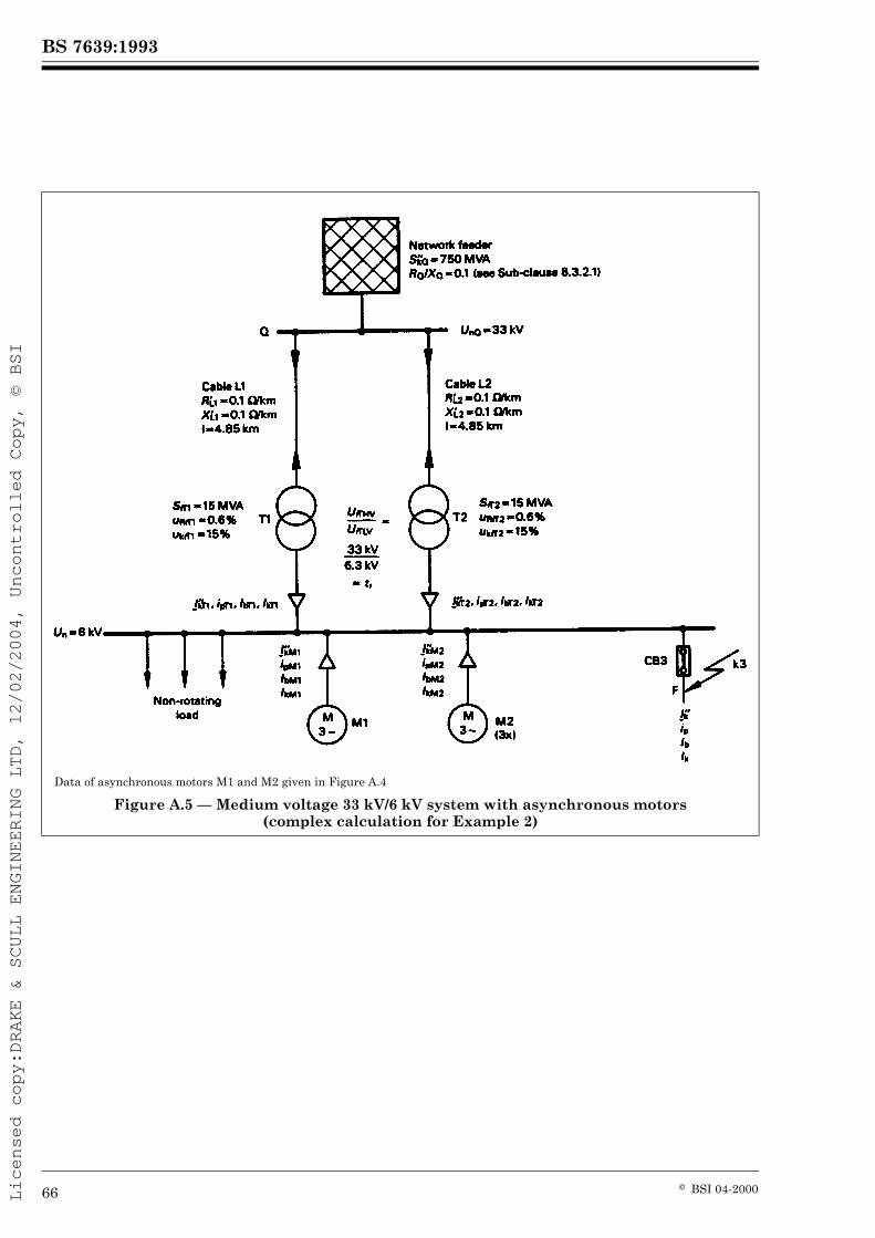
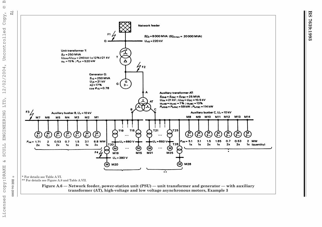
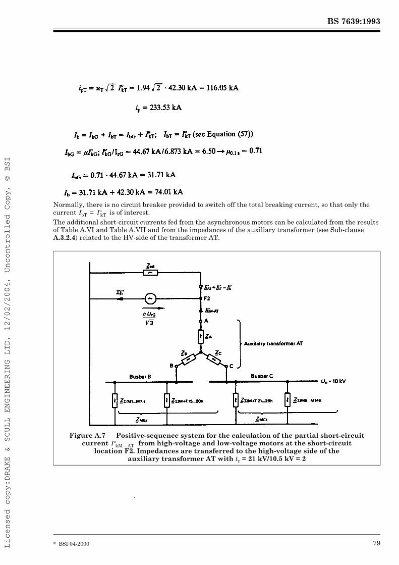
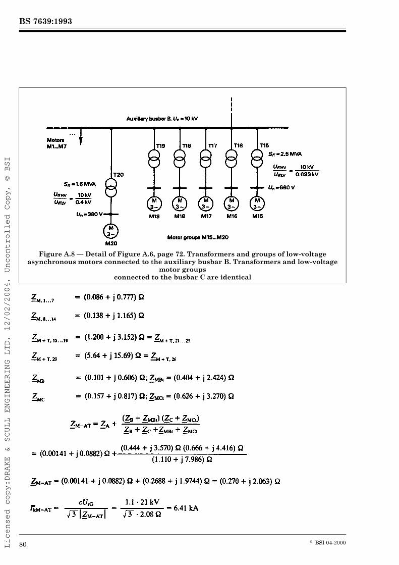
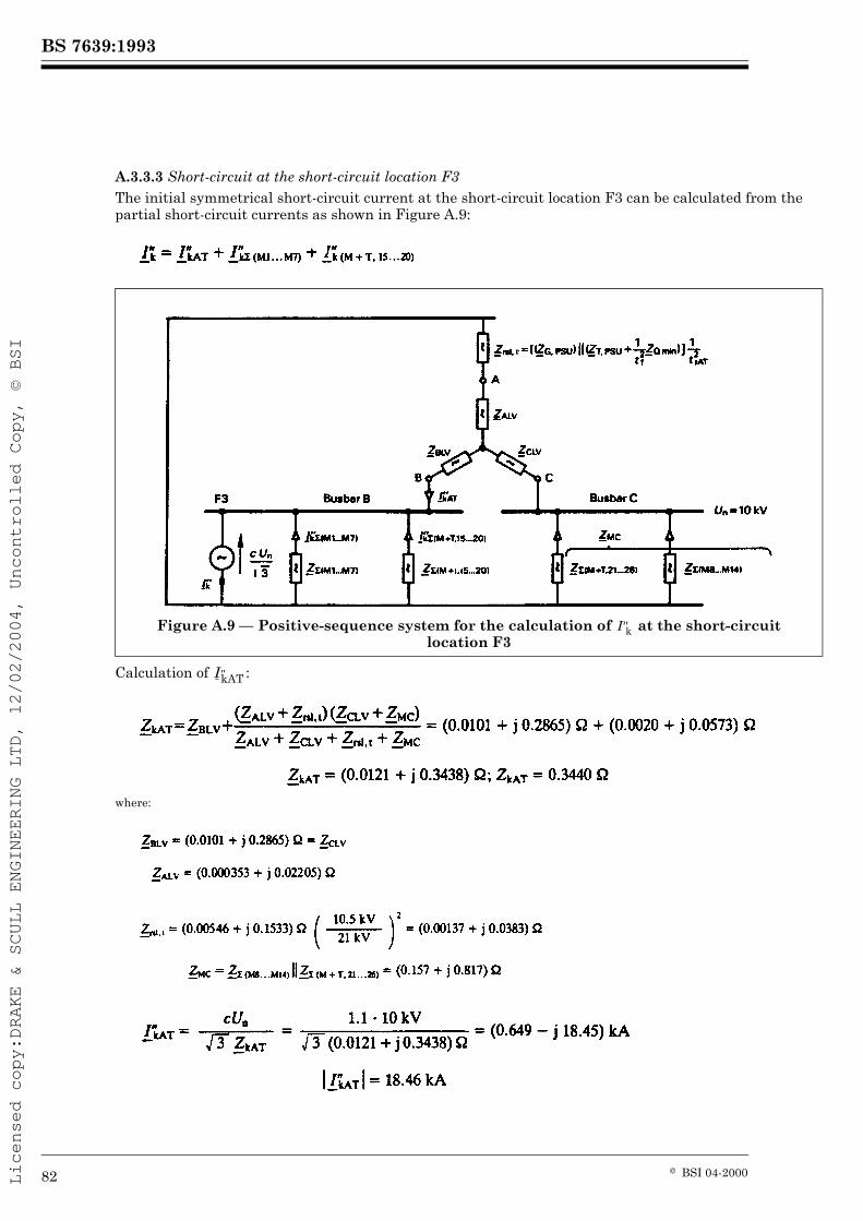
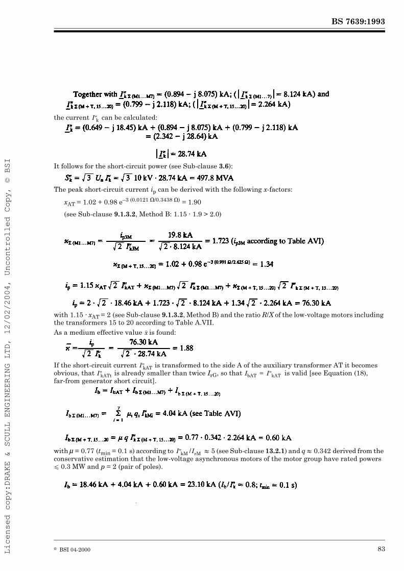
PageFigure A.1 — Low-voltage system with short-circuit locations F1, F2 and F3. Example 1 52Figure A.2 — Positive-sequence system (according to Figure A.1, page 52) for the calculation of and ip at the short-circuit location F1 55Figure A.3 — Positive-sequence, negative-sequence and zero-sequence systems with connections at the short-circuit location F1 for the calculation at a line-to-earth short circuit 58Figure A.4 — Medium voltage 33 kV/6 kV system with asynchronous motors. Example 2 61Figure A.5 — Medium voltage 33 kV/6 kV system with asynchronous motors (complex calculation for Example 2) 66Figure A.6 — Network feeder, power-station unit (PSU) — unit transformer and generator — with auxiliary transformer (AT), high-voltage and low voltage asynchronous motors, Example 3 72Figure A.7 — Positive-sequence system for the calculation of the partial short-circuit current from high-voltage and low-voltage motors at the short-circuit location F2. Impedances are transferred to the high-voltage side of the auxiliary transformer AT with tr = 21 kV/10.5 kV = 2 79Figure A.8 — Detail of Figure A.6, page 72. Transformers and groups of low-voltage asynchronous motors connected to the auxiliary busbar B. Transformers and low-voltage motor groups connected to the busbar C are identical 80Figure A.9 — Positive-sequence system for the calculation of at the short-circuit location F3 82Figure A.10 — Positive-sequence system for the calculation of at the short-circuit location F4 84Table I — Voltage factor c 15Table II — Calculation of short-circuit currents of asynchronous motors in the case of a short circuit at the terminals 50
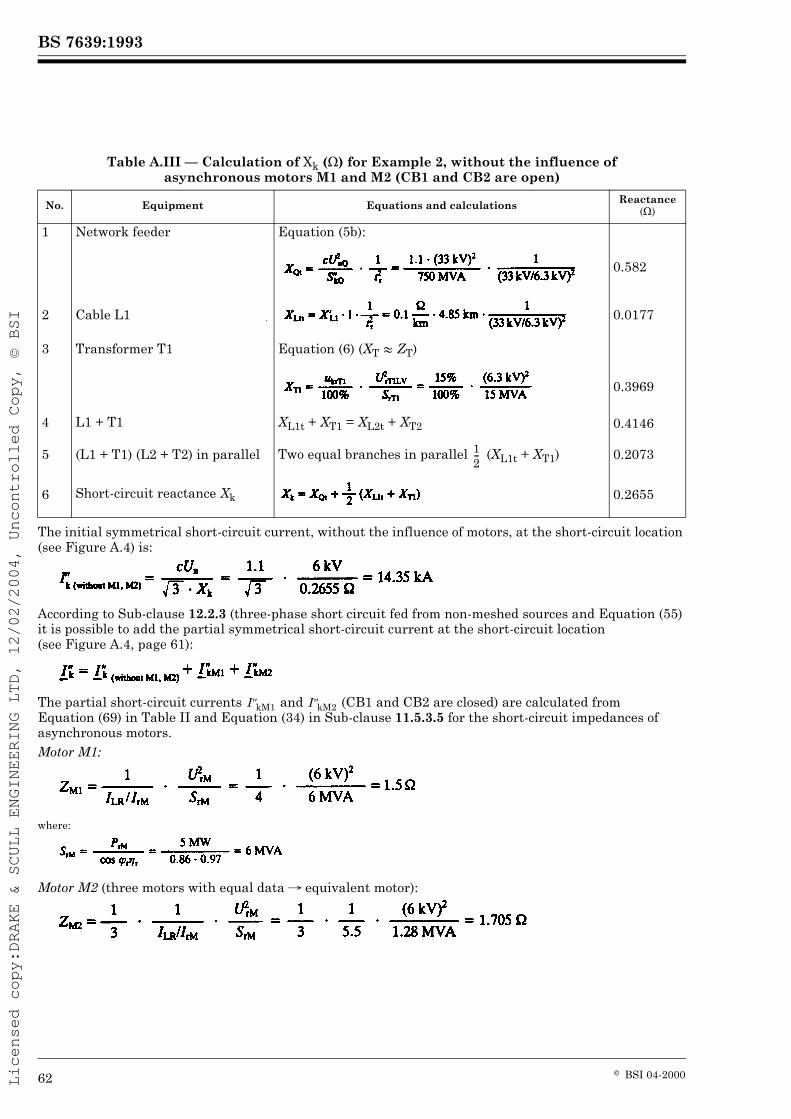
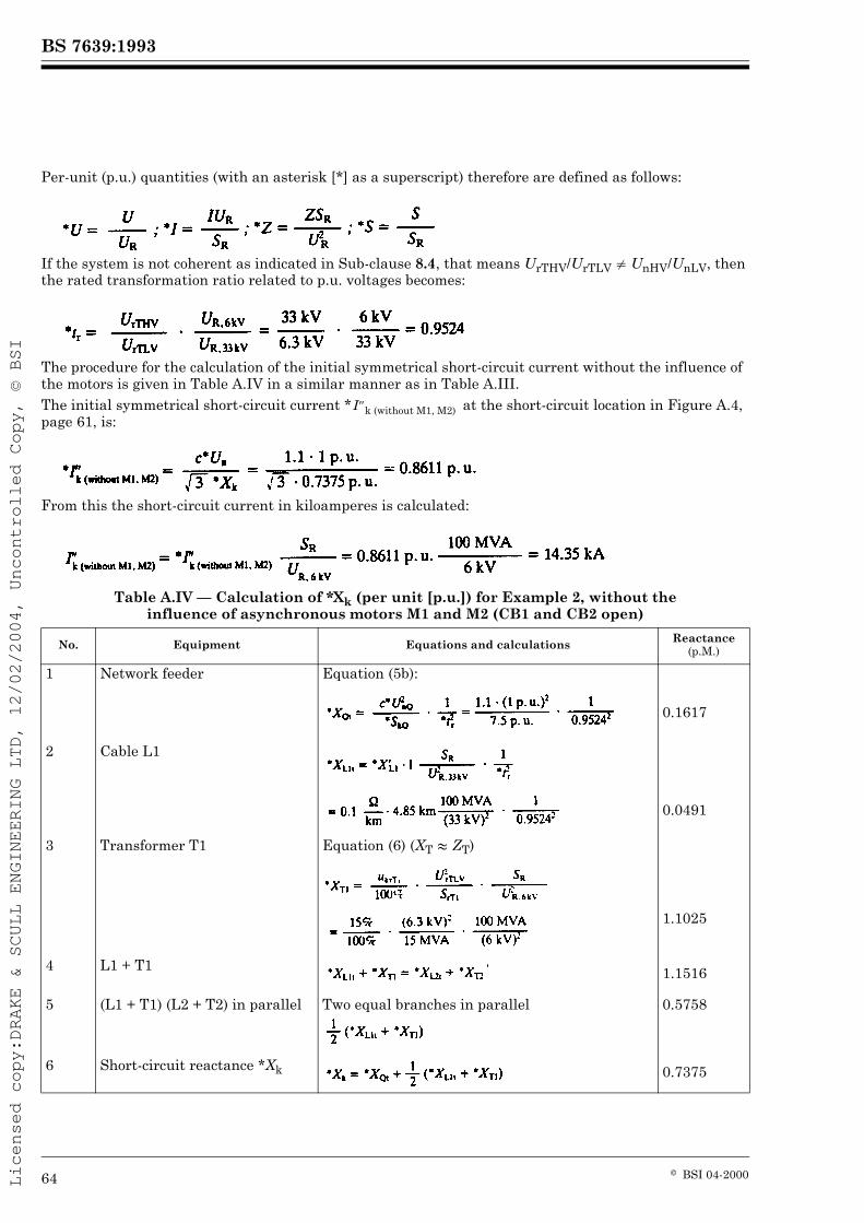
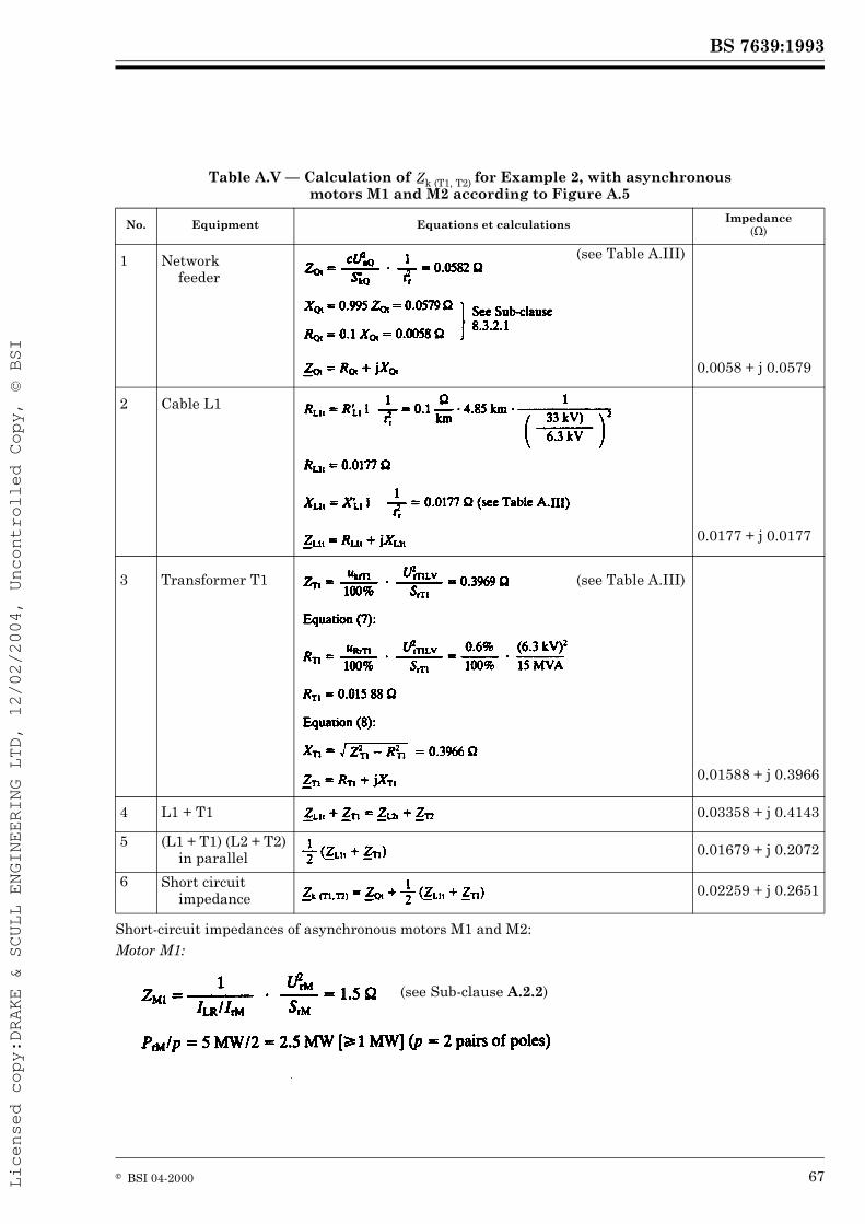
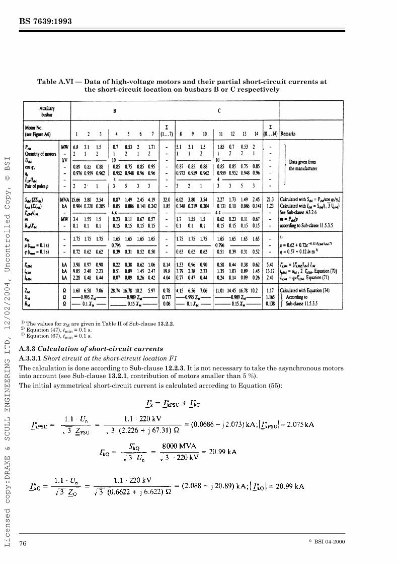
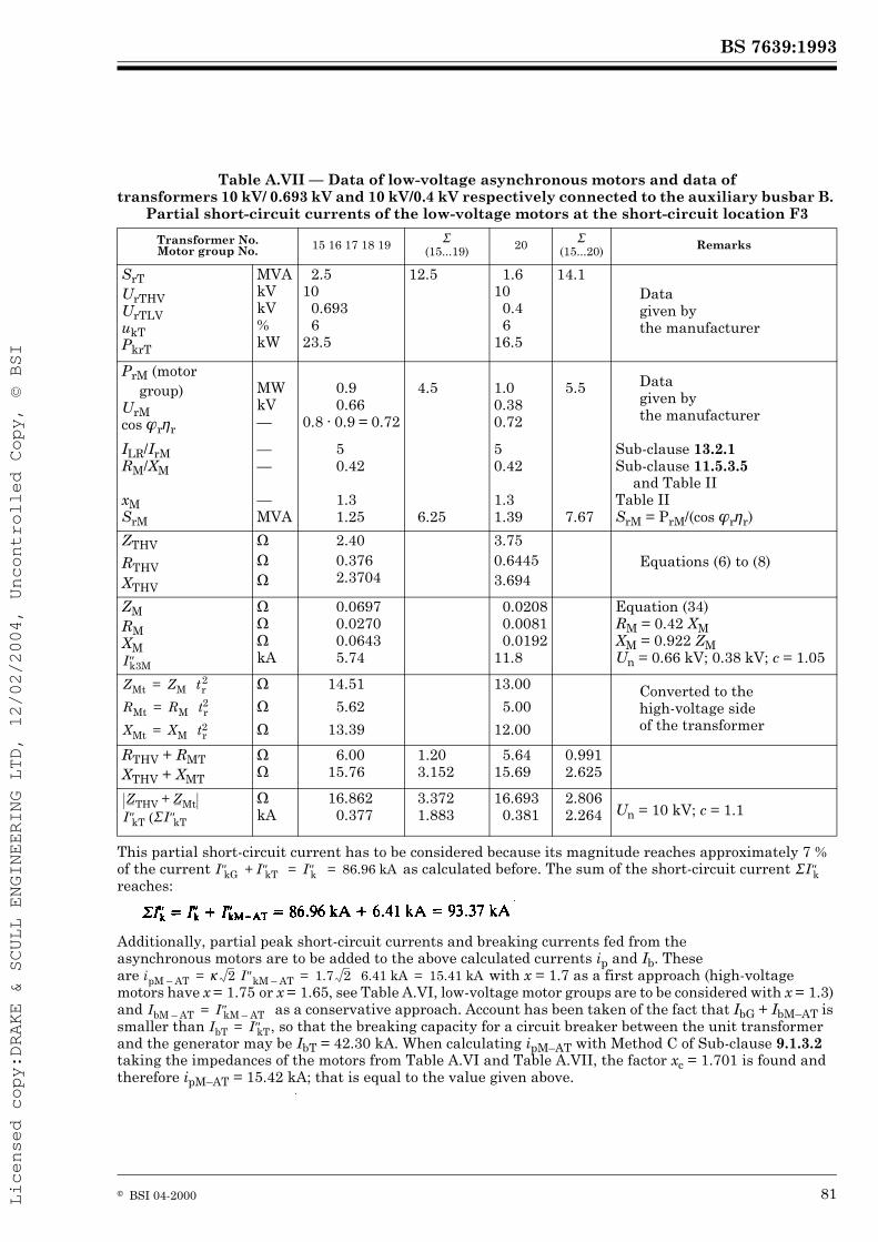
PageTable A.I — Data of equipment for Example 1 and positive-sequence, negative-sequence and zero-sequence short-circuit impedances 54Table A.II — Collection of results for Example 1 (Un = 380 V) 59Table A.III — Calculation of Xk (7) for Example 2, without the influence of asynchronous motors M1 and M2 (CB1 and CB2 are open) 62Table A.IV — Calculation of *Xk (per unit [p.u.]) for Example 2, without the influence of asynchronous motors M1 and M2 (CB1 and CB2 open) 64Table A.V — Calculation of for Example 2, with asynchronous motors M1 and M2 according to Figure A.5 67Table A.VI — Data of high-voltage motors and their partial short-circuit currents at the short-circuit location on busbars B or C respectively 76Table A.VII — Data of low-voltage asynchronous motors and data of transformers 10 kV 0.693 kV and 10 kV/0.4 kV respectively connected to the auxiliary busbar B. Partial short-circuit currents of the low-voltage motors at the short-circuit location F3 81
1 ScopeThis standard is applicable to the calculation of short-circuit currents:
— in low-voltage three-phase a.c. systems,— in high-voltage three-phase a.c. systems with nominal voltages up to 380 kV operating at nominal frequency (50 Hz or 60 Hz).
This standardized procedure is given in such a form as to facilitate as far as possible its use by non-specialist engineers.
2 ObjectThe object of this standard is to establish a general, practicable and concise procedure leading to conservative results with sufficient accuracy. For this purpose, an equivalent voltage source at the short-circuit location is considered, as described under Clause 6. This does not exclude the use of special methods, for example the superposition method, adjusted to particular circumstances, if they give at least the same precision.Short-circuit currents and short-circuit impedances may also be determined by system tests, by measurement on a network analyzer, or with a digital computer. In existing low-voltage systems it is possible to determine the short-circuit impedance on the basis of measurements at the location of the prospective short circuit considered.The calculation of the short-circuit impedance, based on the rated data of the electrical equipment and the topological arrangement of the system has the advantage of being possible both for existing systems and for systems at the planning stage.There are two different short-circuit currents to be calculated which differ in their magnitude:
— the maximum short-circuit current which determines the capacity or rating of electrical equipment;— the minimum short-circuit current which can be a basis, for example, for the selection of fuses and for the setting of protective devices and for checking the run-up of motors.One has to distinguish between— systems with short-circuit currents having no a.c. component decay (far-from-generator short circuit), treated in Section 1,— systems with short-circuit currents having decaying a.c. components (near-to-generator short circuit), treated in Section 2. This section also includes the influence of motors.
This standard does not cover short-circuit currents deliberately created under controlled conditions (short-circuit testing stations).This standard does not deal with installations on board ships and areoplanes.For the calculation of the thermal equivalent short-circuit currents see Section 2 of IEC Publication 865.An application guide, dealing with non-meshed low-voltage three-phase a.c. systems and a technical report on the derivation of the parameters and various calculation factors of this standard are under consideration.
3 DefinitionsFor the purpose of this standard, the following definitions apply. Reference is made to the International Electrotechnical Vocabulary (IEV) [IEC Publication 50] when applicable.
3.1 short circuit
the accidental or intentional connection, by a relatively low resistance or impedance, of two or more points in a circuit which are normally at different voltages (IEV 151-03-41)
3.2 short-circuit current
an over-current resulting from a short circuit due to a fault or an incorrect connection in an electric circuit (IEV 441-11-07)NOTE It is necessary to distinguish between the short-circuit current at the short-circuit location and in the network branches.
the current that would flow if the short circuit were replaced by an ideal connection of negligible impedance without any change of the supplyNOTE The current in a three-phase short circuit is assumed to be made simultaneously in all poles. Investigations of non-simultaneous short circuits, which can lead to higher aperiodic components of short-circuit current, are beyond the scope of this standard.
3.4 symmetrical short-circuit current
the r.m.s. value of the a.c. symmetrical component of a prospective (available) short-circuit current (see Sub-clause 3.3), the aperiodic component of current, if any, being neglected
3.5 initial symmetrical short-circuit current
the r.m.s. value of the a.c. symmetrical component of a prospective (available) short-circuit current (see Sub-clause 3.3) applicable at the instant of short circuit if the impedance remains at zero-time value (see Figure 1 and Figure 12, pages 11 and 31)
3.6 initial symmetrical short-circuit (apparent) power
the fictive value determined as a product of the initial symmetrical short-circuit current (see Sub-clause 3.5), the nominal system voltage Un (see Sub-clause 3.14), and the factor :
3.7 D.C. (aperiodic) component iDC of short-circuit current
the mean value between the top and bottom envelope of a short-circuit current decaying from an initial value to zero according to Figure 1 and Figure 12
3.8 peak short-circuit current ipthe maximum possible instantaneous value of the prospective (available) short-circuit current (see Figure 1 and Figure 12)NOTE The magnitude of the peak short-circuit current varies in accordance with the moment at which the short circuit occurs. The calculation of the peak three-phase short-circuit current ip applies for the phase conductor and moment at which the greatest possible short-circuit current exists. Sequential faults are not considered. For three-phase short circuits it is assumed that the short circuit occurs simultaneously in all phase conductors.
3.9 symmetrical short-circuit breaking current Ib
the r.m.s. value of an integral cycle of the symmetrical a.c. component of the prospective short-circuit current at the instant of contact separation of the first pole of a switching device
3.10 steady-state short-circuit current Ik
The r.m.s. value of the short-circuit current which remains after the decay of the transient phenomena (see Figure 1 and Figure 12, pages 11 and 31)
3.11 symmetrical locked-rotor current ILR
The highest symmetrical r.m.s. current of an asynchronous motor with locked rotor fed with rated voltage UrM at rated frequency
3.12 equivalent electric circuit
a model to describe the behaviour of a circuit by means of a network of ideal elements (IEV 131-01-33)
an active element which can be represented by an ideal voltage source independent of all currents and voltages in the circuit, in series with a passive circuit element (IEV 131-01-37)
3.14 nominal system voltage Un
voltage (line-to-line) by which a system is designated and to which certain operating characteristics are referred. Values are given in IEC Publication 38
3.15 equivalent voltage source cUn/
the voltage of an ideal source applied at the short-circuit location in the positive-sequence system for calculating the short-circuit current according to Clause 6. This is the only active voltage of the network
3.16 voltage factor c
the ratio between the equivalent voltage source and the nominal system voltage Un divided by . The values are given in Table INOTE The introduction of a voltage factor c is necessary for various reasons. These are:
— voltage variations depending on time and place,— changing of transformer taps,— neglecting loads and capacitances by calculations according to Clause 6,— the subtransient behaviour of generators and motors.
3.17 subtransient voltage E¾: of a synchronous machine
the r.m.s. value of the symmetrical internal voltage of a synchronous machine which is active behind the subtransient reactance at the moment of short circuit
3.18 far-from-generator short circuit
a short circuit during which the magnitude of the symmetrical a.c. component of prospective (available) short-circuit current remains essentially constant (see Clause 7)
3.19 near-to-generator short circuit
a short circuit to which at least one synchronous machine contributes a prospective initial symmetrical short-circuit current which is more than twice the generator’s rated current, or a short circuit to which synchronous and asynchronous motors contribute more than 5 % of the initial symmetrical short-circuit current without motors (see Clause 10)
3.20 Short-circuit impedances at the short-circuit location F
3.20.1 positive-sequence short-circuit impedance of a three-phase a.c. system
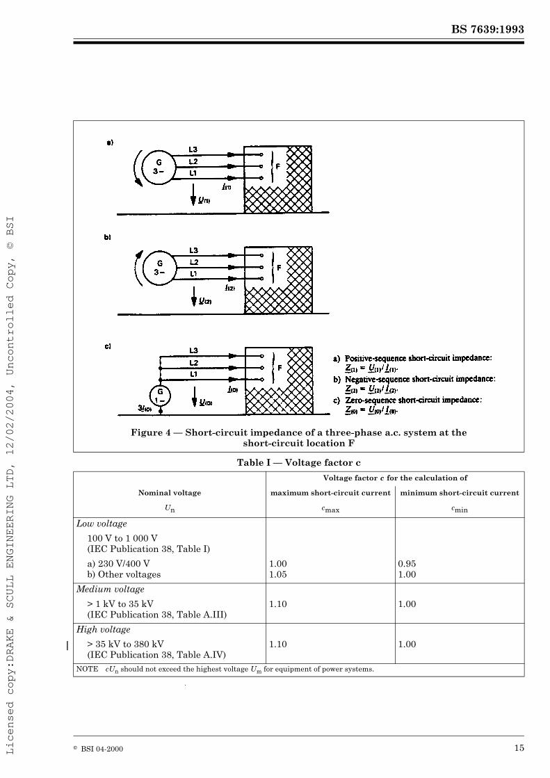
the impedance of the positive-sequence system as viewed from the short-circuit location [see Sub-clause 8.3.1 and Figure 4 a), page 15]
3.20.2 negative-sequence short-circuit impedance of a three-phase a.c. system
the impedance of the negative-sequence system as viewed from the short-circuit location [see Sub-clause 8.3.1 and Figure 4 b), page 15]
3.20.3 zero-sequence short-circuit impedance of a three-phase a.c. system
the impedance of the zero-sequence system as viewed from the short-circuit location [see Sub-clause 8.3.1 and Figure 4 c), page 15]. It includes three times the neutral-to-earth impedance 3
3.20.4 short-circuit impedance of a three-phase a.c. system
abbreviated expression for the positive-sequence short-circuit impedance according to Sub-clause 3.20.1 for the calculation of three-phase short-circuit currents
3.21 Short-circuit impedances of electrical equipment
3.21.1 positive-sequence short-circuit impedance of electrical equipment
the ratio of the line-to-neutral voltage to the short-circuit current of the corresponding phase of electrical equipment when fed by a symmetrical positive-sequence system of voltages (see Sub-clause 8.3.2)
NOTE Index of symbol may be omitted if there is no possibility of confusion with the negative-sequence and the zero-sequence short-circuit impedances.
3.21.2 negative-sequence short-circuit impedance of electrical equipment
the ratio of the line-to-neutral voltage to the short-circuit current of the corresponding phase of electrical equipment when fed by a symmetrical negative-sequence system of voltages (see Sub-clause 8.3.2)
3.21.3 zero-sequence short-circuit impedance of electrical equipment
the ratio of the line-to-earth voltage to the short-circuit current of one phase of electrical equipment when fed by an a.c. voltage source, if the three parallel phase conductors are used for the outgoing current and a fourth line and/or earth is joint return (see Sub-clause 8.3.2)3.22 subtransient reactance of a synchronous machine
the effective reactance at the moment of short circuit. For the calculation of short-circuit currents the saturated value of is takenNOTE When the reactance in ohms is divided by the rated impedance of the synchronous machine, the result in per unit is represented by a small letter .
3.23 minimum time delay tmin of a circuit breaker
the shortest time between the beginning of the short-circuit current and the first contact separation of one pole of the switching deviceNOTE The time tmin is the sum of the shortest possible operating time of an instantaneous relay and the shortest opening time of a circuit breaker. It does not take into account adjustable time delays of tripping devices.
4 Symbols, subscripts and superscriptsSymbols of complex quantities are underlined, for example: .All equations are written without specifying units. The symbols represent quantities possessing both numerical values and dimensions that are independent of units, provided a coherent unit system is chosen, for example, the International System of Units (SI).
4.1 Symbols
A Initial value of aperiodic componentc Voltage factor
Equivalent voltage source (r.m.s.)
Ew Subtransient voltage of a synchronous machine
f Frequency (50 Hz or 60 Hz)Ib Symmetrical short-circuit breaking current (r.m.s.)
Ik Steady-state short-circuit current (r.m.s.)
IkP Steady-state short-circuit current at the terminals (poles) of a generator with compound excitation
Initial symmetrical short-circuit current (r.m.s.)
ILR Locked-rotor current of an asynchronous motor
iDC Decaying aperiodic component of short-circuit current
ip Peak short-circuit current
K Correction factor for impedancesPkvT Total loss in transformer windings at rated current
q Factor for the calculation of breaking currents of asynchronous motorsqn Nominal cross section
R resp. r Resistance, absolute respectively relative valueRG Fictitious resistance of a synchronous machine when calculating and ip
Initial symmetrical short-circuit power (apparent power)
Sr Rated apparent power of electrical equipment
tf Fictitious transformation ratio
tmin Minimum time delay
tr Rated transformation ratio (tap changer in main position); tr U 1
Un Nominal system voltage, line-to-line (r.m.s.)
Ur Rated voltage, line-to-line (r.m.s.)
uks Rated short-circuit voltage in percent
uRr Rated ohmic voltage in percent
Positive-, negative-, zero-sequence voltage
X resp. x Reactance, absolute respectively relative valueXd resp. Xq Synchronous reactance, direct axis respectively quadrature axis
XdP Fictitious reactance of a generator with compound excitation in the case of steady-state short circuit at the terminals (poles) if the excitation is taken into account
resp. Subtransient reactance of a synchronous machine (saturated value), direct axis respectively quadrature axis
Xd est Reciprocal of the short-circuit ratio
Z resp. z Impedance, absolute respectively relative value
Short-circuit impedance of a three-phase a.c. system
Positive-sequence short-circuit impedance
Negative-sequence short-circuit impedance
Zero-sequence short-circuit impedance
½ Efficiency of asynchronous motorsx Factor for the calculation of the peak short-circuit currentÆ Factor for the calculation of the steady-state short-circuit currentÈ Factor for the calculation of the symmetrical short-circuit breaking currentÈ0 Absolute permeability of vacuum, È0 = 4;/10–7 H/m
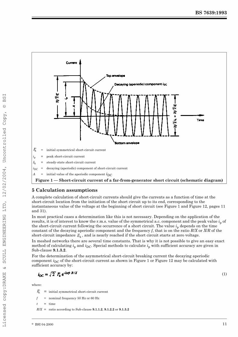
5 Calculation assumptionsA complete calculation of short-circuit currents should give the currents as a function of time at the short-circuit location from the initiation of the short circuit up to its end, corresponding to the instantaneous value of the voltage at the beginning of short circuit (see Figure 1 and Figure 12, pages 11 and 31).In most practical cases a determination like this is not necessary. Depending on the application of the results, it is of interest to know the r.m.s. value of the symmetrical a.c. component and the peak value ip of the short-circuit current following the occurrence of a short circuit. The value ip depends on the time constant of the decaying aperiodic component and the frequency f, that is on the ratio R/X or X/R of the short-circuit impedance , and is nearly reached if the short circuit starts at zero voltage.In meshed networks there are several time constants. That is why it is not possible to give an easy exact method of calculating ip and iDC. Special methods to calculate ip with sufficient accuracy are given in Sub-clause 9.1.3.2.For the determination of the asymmetrical short-circuit breaking current the decaying aperiodic component iDC of the short-circuit current as shown in Figure 1 or Figure 12 may be calculated with sufficient accuracy by:
where:
= initial symmetrical short-circuit current
ip = peak short-circuit current
Ik = steady-state short-circuit current
iDC = decaying (aperiodic) component of short-circuit current
A = initial value of the aperiodic component iDC
Figure 1 — Short-circuit current of a far-from-generator short circuit (schematic diagram)
(1)
= initial symmetrical short-circuit current
f = nominal frequency 50 Hz or 60 Hz
t = time
R/X = ratio according to Sub-clause 9.1.1.2, 9.1.2.2 or 9.1.3.2
In meshed networks according to Sub-clause 9.1.3.2 — Method A — the right hand side of equation (1) should be multiplied by 1.15. According to Sub-clause 9.1.3.2 — Method B — the equivalent frequency should be selected as follows:
where f = 50 Hz or 60 Hz.Furthermore, the calculation of maximum and minimum short-circuit currents is based on the following simplifications:
1) For the duration of the short circuit there is no change in the number of circuits involved, that is, a three-phase short-circuit remains three phase and a line-to-earth short circuit remains line-to-earth during the time of short circuit.2) Tap changers of the transformers are assumed to be in main position.3) Arc resistances are not taken into account.
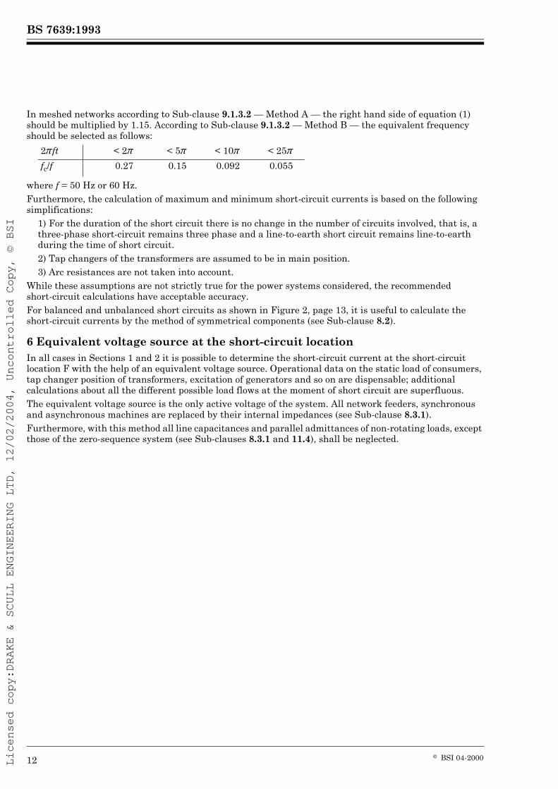
While these assumptions are not strictly true for the power systems considered, the recommended short-circuit calculations have acceptable accuracy.For balanced and unbalanced short circuits as shown in Figure 2, page 13, it is useful to calculate the short-circuit currents by the method of symmetrical components (see Sub-clause 8.2).
6 Equivalent voltage source at the short-circuit locationIn all cases in Sections 1 and 2 it is possible to determine the short-circuit current at the short-circuit location F with the help of an equivalent voltage source. Operational data on the static load of consumers, tap changer position of transformers, excitation of generators and so on are dispensable; additional calculations about all the different possible load flows at the moment of short circuit are superfluous.The equivalent voltage source is the only active voltage of the system. All network feeders, synchronous and asynchronous machines are replaced by their internal impedances (see Sub-clause 8.3.1).Furthermore, with this method all line capacitances and parallel admittances of non-rotating loads, except those of the zero-sequence system (see Sub-clauses 8.3.1 and 11.4), shall be neglected.
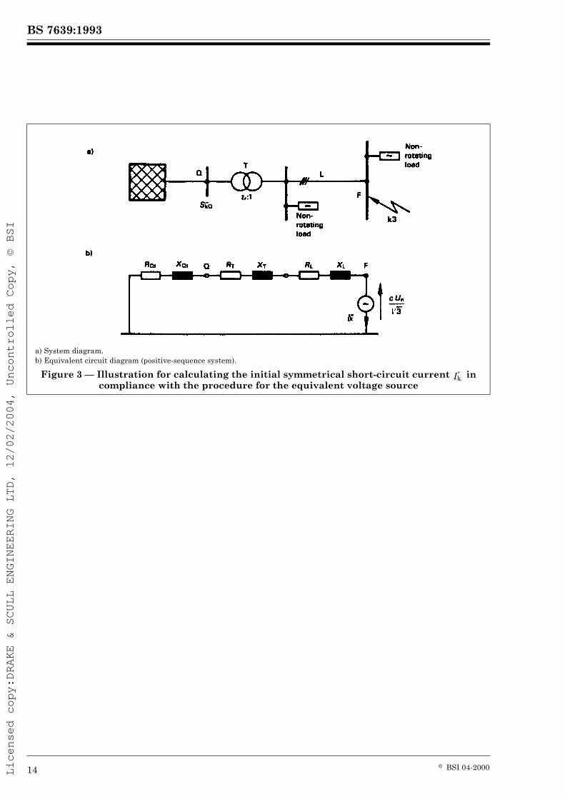
Finally high-voltage transformers in many cases are equipped with regulators and tap changers operating under load flow conditions, whereas transformers feeding low-voltage systems have normally only a few taps, for example + 2.5 % or + 4 %. The actual regulator or tap changer position of transformers in the case of far-from-generator short circuits may be disregarded without unacceptable loss of accuracy by use of this method.The modelling of the system equipment by means of impedances according to Sub-clauses 8.3.2 and 11.5.3 applies in conjunction with the equivalent voltage source at the short-circuit location irrespective of whether a far-from-generator short-circuit according to Section 1 or a near-to-generator short-circuit according to Section 2 is involved.Figure 3, page 14, shows an example of the equivalent voltage source at the short-circuit location F as the sole active voltage of the system in the case of a low-voltage system fed by a single transformer. All other active voltages in the system are assumed to be zero. Thus the network feeder in Figure 3 a), page 14, is represented only by its internal impedance ZQ (see Sub-clause 8.3.2.1). Parallel admittances (e.g. line capacitances and passive loads) are not to be considered when calculating short-circuit currents in accordance with Figure 3 b), page 14.The equivalent voltage source (see Sub-clause 3.15) at the short-circuit location F is composed of the voltage factor c, the nominal system voltage Un, and . The voltage factor c is different for the calculation of maximum or minimum short-circuit currents. If there are no national standards, it seems adequate to choose a voltage factor c according to Table I, considering that the highest voltage in a normal system does not differ, on average, by more than + 5 % (LV) or + 10 % (HV) approximately from the nominal voltage.
a) Balanced three-phase short circuit.
b) Line-to-line short circuit without earth connection.
c) Line-to-line short circuit with earth connection.
d) Line-to-earth short circuit.
Figure 2 — Characterization of short circuits and their currents. The direction of current arrows is chosen arbitrarily
a) System diagram.b) Equivalent circuit diagram (positive-sequence system).
Figure 3 — Illustration for calculating the initial symmetrical short-circuit current in compliance with the procedure for the equivalent voltage source
In this way the equivalent voltage source for the calculation of the maximum short-circuit current can be established, according to Table I, by:
Section 1. Systems with short-circuit currents having no a.c. component decay (far-from-generator short circuits)
7 GeneralThis section refers to short circuits where there is no change for the duration of the short circuit in the voltage or voltages that caused the short-circuit current to develop (i.e. a quasi-stationary voltage condition), nor any significant change in the impedance of the circuit (i.e. constant and linear impedances).Therefore, the prospective (available) short-circuit current can be considered as the sum of the following two components:
— the a.c. component with constant amplitude during the whole short circuit,— the aperiodic component beginning with an initial value A and decaying to zero.
Figure 1, page 11, gives schematically the general course of the short-circuit current in the case of a far-from-generator short circuit. The symmetrical a.c. components and Ik are r.m.s. values and are nearly equal in magnitude.This assumption is generally satisfied in power systems fed from extended high-voltage systems through transformers, that is in the case of a far-from-generator short circuit.Single-fed short-circuits supplied by a transformer according to Figure 3, page 14, may a priori be regarded as far-from-generator short circuits if XTLV W 2 XQt with XQt to be calculated in accordance with Sub-clause 8.3.2.1 and XTLV in accordance with Sub-clause 8.3.2.2.
8 Short-circuit parameters8.1 Balanced short circuit
The balanced three-phase short circuit of a three-phase a.c. system in accordance with Figure 2 a), page 13, is of special interest, because this kind of fault often leads to the highest values of prospective (available) short-circuit current and the calculation becomes particularly simple on account of the balanced nature of the short circuit.In calculating the short-circuit current, it is sufficient to take into account only the positive-sequence short-circuit impedance as seen from the fault location (see Sub-clause 8.3.1).Details of calculation are given in Clause 9.
8.2 Unbalanced short circuit
The following types of unbalanced (asymmetrical) short circuits are treated in this standard:— line-to-line short circuit without earth connection [see Figure 2 b), page 13],— line-to-line short circuit with earth connection [see Figure 2 c), page 13],— line-to-earth short circuit [see Figure 2 d), page 13].
As a rule, the three-phase short-circuit current is the largest. In the event of a short circuit near to a transformer with neutral earthing or a neutral-earthing transformer, the line-to-earth short-circuit current may be greater than the three-phase short-circuit current. This applies in particular to transformer of vector group Yz, Dy and Dz when earthing the y- or z-winding on the low voltage side of the transformer.In three-phase systems the calculation of the current values resulting from unbalanced short circuits is simplified by the use of the method of symmetrical components which requires the calculation of three independent system components, avoiding any coupling of mutual impedances.
Using this method, the currents in each line are found by superposing the currents of three symmetrical component systems:
— positive-sequence current ,— negative-sequence current ,— zero-sequence current .
Taking the line L1 as reference, the currents , and are given by:
Each of the three symmetrical component systems has its own impedance (see Sub-clause 8.3).The method of the symmetrical components postulates that the system impedances are balanced, for example in the case of transposed lines. The results of the short-circuit calculation have an acceptable accuracy also in the case of untransposed lines.
8.3 Short-circuit impedances
For the purpose of this standard, one has to make a distinction between short-circuit impedances at the short-circuit location F and short-circuit impedances of individual electrical equipment. According to the calculation with symmetrical components positive-sequence, negative-sequence and zero-sequence short-circuit impedances shall be considered.
8.3.1 Short-circuit impedances at the short-circuit location F
The positive-sequence short-circuit impedance at the short-circuit location F is obtained according to Figure 4 a), page 15, when a symmetrical system of voltages of positive-sequence phase order is applied to the short-circuit location F and all synchronous and asynchronous machines are replaced by their internal impedances. When calculating short-circuit currents in accordance with Clause 9, all line capacitances and parallel admittances of non-rotating loads are neglected.For the calculation of balanced three-phase short circuits, the positive-sequence impedance is the only relevant impedance. In this case (see Sub-clauses 3.20.1 and 3.20.4).The negative-sequence short-circuit impedance at the short-circuit location F is obtained according to Figure 4 b), page 15, when a symmetrical system of voltages of negative-sequence phase order is applied to the short-circuit location F. When calculating short-circuit currents in accordance with Clause 9, all line capacitances and parallel admittances of non-rotating loads are neglected.The values of positive-sequence and negative-sequence impedances can differ from each other only in the case of rotating machines. In this section, where far-from-generator short circuits are calculated, it is generally allowed to take .The zero-sequence short-circuit impedance at the short-circuit location F is obtained according to Figure 4 c), page 15, if an a.c. voltage is applied between the short-circuited lines and the common returns (e.g. earth system, neutral conductor, earth wires, cable sheaths, cable armouring).When calculating unbalanced short-circuit currents in medium or high-voltage systems and applying an equivalent voltage source at the short-circuit location, the line zero-sequence capacitances and zero-sequence parallel admittances of non-rotating loads are to be considered for isolated neutral systems and resonant earthed systems.Neglecting the line zero-sequence capacitances in earthed neutral systems leads to results which are higher than the real values of the short-circuit currents. The deviation depends on several parameters of the system, for example the length of the line between transformers with neutral earthing.In low-voltage systems, line capacitances and parallel admittances of non-rotating loads can be neglected.
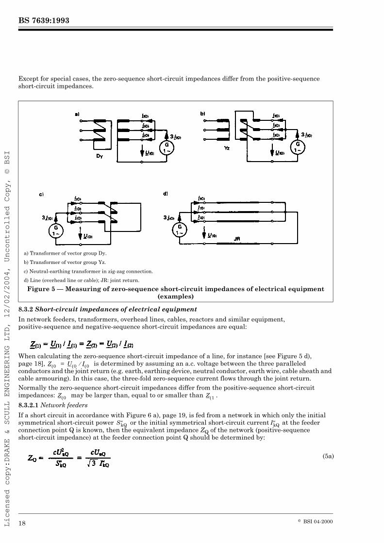
Except for special cases, the zero-sequence short-circuit impedances differ from the positive-sequence short-circuit impedances.
8.3.2 Short-circuit impedances of electrical equipment
In network feeders, transformers, overhead lines, cables, reactors and similar equipment, positive-sequence and negative-sequence short-circuit impedances are equal:
When calculating the zero-sequence short-circuit impedance of a line, for instance [see Figure 5 d), page 18], is determined by assuming an a.c. voltage between the three paralleled conductors and the joint return (e.g. earth, earthing device, neutral conductor, earth wire, cable sheath and cable armouring). In this case, the three-fold zero-sequence current flows through the joint return.Normally the zero-sequence short-circuit impedances differ from the positive-sequence short-circuit impedances: may be larger than, equal to or smaller than .
8.3.2.1 Network feeders
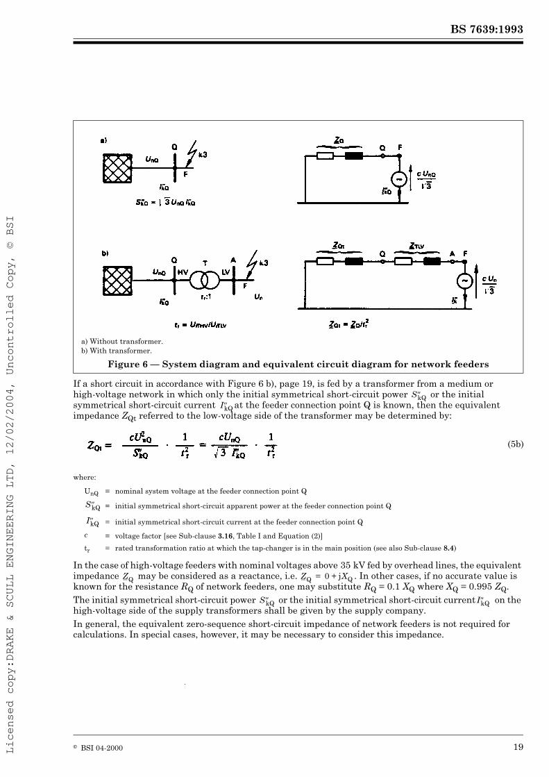
If a short circuit in accordance with Figure 6 a), page 19, is fed from a network in which only the initial symmetrical short-circuit power or the initial symmetrical short-circuit current at the feeder connection point Q is known, then the equivalent impedance ZQ of the network (positive-sequence short-circuit impedance) at the feeder connection point Q should be determined by:
a) Transformer of vector group Dy.
b) Transformer of vector group Yz.
c) Neutral-earthing transformer in zig-zag connection.
d) Line (overhead line or cable); JR: joint return.
Figure 5 — Measuring of zero-sequence short-circuit impedances of electrical equipment (examples)
If a short circuit in accordance with Figure 6 b), page 19, is fed by a transformer from a medium or high-voltage network in which only the initial symmetrical short-circuit power or the initial symmetrical short-circuit current at the feeder connection point Q is known, then the equivalent impedance ZQt referred to the low-voltage side of the transformer may be determined by:
where:
In the case of high-voltage feeders with nominal voltages above 35 kV fed by overhead lines, the equivalent impedance may be considered as a reactance, i.e. . In other cases, if no accurate value is known for the resistance RQ of network feeders, one may substitute RQ = 0.1 XQ where XQ = 0.995 ZQ.The initial symmetrical short-circuit power or the initial symmetrical short-circuit current on the high-voltage side of the supply transformers shall be given by the supply company.In general, the equivalent zero-sequence short-circuit impedance of network feeders is not required for calculations. In special cases, however, it may be necessary to consider this impedance.
a) Without transformer.b) With transformer.
Figure 6 — System diagram and equivalent circuit diagram for network feeders
(5b)
UnQ = nominal system voltage at the feeder connection point Q
= initial symmetrical short-circuit apparent power at the feeder connection point Q
= initial symmetrical short-circuit current at the feeder connection point Q
c = voltage factor [see Sub-clause 3.16, Table I and Equation (2)]
tr = rated transformation ratio at which the tap-changer is in the main position (see also Sub-clause 8.4)
The positive-sequence short-circuit impedances of two-winding transformers can be calculated from the rated transformer data as follows:
where:
The necessary data may be taken from rating plates or obtained from the manufacturer.The resistive component can be calculated from the total loss in the windings at the rated current.The ratio X/R generally increases with transformer size. For large transformers the resistance is so small that the impedance may be assumed to consist only of reactance when calculating short-circuit current magnitude. Resistance must be considered if the peak short-circuit current ip or the decaying aperiodic component iDC is to be calculated.The zero-sequence short-circuit impedances of transformers with two or more windings may be obtained from the manufacturer.NOTE It is sufficient for transformers with tap-changers to determine ZT in accordance with formula (6) for the main position and to convert the impedances, currents and voltages according to Sub-clause 8.4 using the rated transformation ratio tr corresponding to the tap-changer in the main position.Special considerations are necessary, only if:
— a single fed short-circuit current is calculated and the short-circuit current has the same direction as the operational current before the short-circuit occurs [short circuit on the low-voltage side of one transformer or parallel transformers with tap changers according to Figure 3, page 14, or Figure 6 b), page 19],— it is possible to change the transformation ratio of a transformer with the tap changer in a wide range, UTHV = UrTHV (1 ± pT) with pT > 0.05,— the minimum short-circuit voltage uk min is considerably lower than the rated short-circuit voltage in the main position (uk min < ukr),— the voltage during operation is considerably higher than the nominal system voltage (U W 1.05 Un).
In the case of three-winding transformers, the positive-sequence short-circuit impedances , and referring to Figure 7, page 22, can be calculated by the three short-circuit impedances (related to side A of the transformer):
(6)
(7)
(8)
UrT = rated voltage of the transformer on the high-voltage or low-voltage sideIrT = rated current of the transformer on the high-voltage or low-voltage sideSrT = rated apparent power of the transformerPkrT = total loss of the transformer in the windings at rated currentukr = rated short-circuit voltage, in per centuRr = rated ohmique voltage, in per cent
The positive-sequence short-circuit impedances may be calculated from the conductor data, such as the cross sections and the centre-distances of the conductors.For measurement of the zero-sequence short-circuit impedances , see Sub-clause 8.3.2 and Figure 5 d), page 18. Sometimes it is possible to calculate the zero-sequence impedances with the ratios R(0)L/RL et X(0)L/XL.The impedances and of low-voltage and high-voltage cables depend on national techniques and standards and may be taken from text-books or manufacturer’s data.The effective resistance per unit length of overhead lines at the medium conductor temperature 20 °C may be calculated from the nominal cross section qn and the resistivity Õ:
with:
and
(10a)
(10b)
(10c)
UrTA = rated voltageSrTAB = rated apparent power between sides A and BSrTAC = rated apparent power between sides A and CSrTBC = rated apparent power between sides B and CukrAB = rated short-circuit voltage, given in percent, between sides A and BukrAC = rated short-circuit voltage, given in percent, between sides A and CukrBC = rated short-circuit voltage, given in percent, between sides B and C
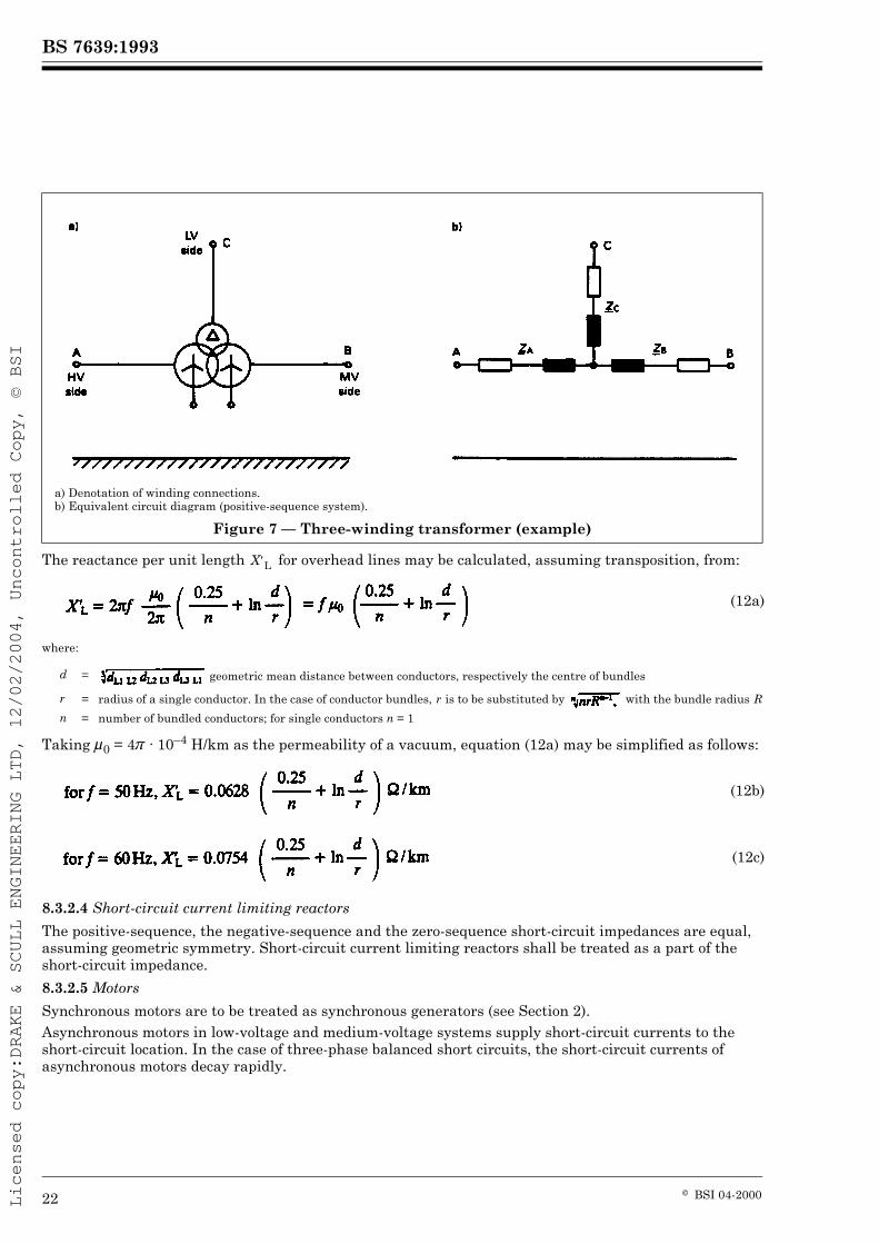
The reactance per unit length for overhead lines may be calculated, assuming transposition, from:
where:
Taking È0 = 4Ï · 10–4 H/km as the permeability of a vacuum, equation (12a) may be simplified as follows:
8.3.2.4 Short-circuit current limiting reactors
The positive-sequence, the negative-sequence and the zero-sequence short-circuit impedances are equal, assuming geometric symmetry. Short-circuit current limiting reactors shall be treated as a part of the short-circuit impedance.
8.3.2.5 Motors
Synchronous motors are to be treated as synchronous generators (see Section 2).Asynchronous motors in low-voltage and medium-voltage systems supply short-circuit currents to the short-circuit location. In the case of three-phase balanced short circuits, the short-circuit currents of asynchronous motors decay rapidly.
a) Denotation of winding connections.b) Equivalent circuit diagram (positive-sequence system).
Figure 7 — Three-winding transformer (example)
(12a)
d = geometric mean distance between conductors, respectively the centre of bundles
r = radius of a single conductor. In the case of conductor bundles, r is to be substituted by with the bundle radius Rn = number of bundled conductors; for single conductors n = 1
It is not necessary to take into account asynchronous motors or groups of asynchronous motors which have a total rated current less than 1 % of the initial symmetrical short-circuit current calculated without the influence of motors. The supplement of short-circuit currents of asynchronous motors to the current may be neglected if:
where:
In other cases see Section 2.
8.4 Conversion of impedances, currents and voltages
When calculating short-circuit currents in systems with different voltage levels, it is necessary to convert impedances, currents and voltages from one level to the other [e.g. see Figure 3 b), page 14]. For per unit or other similar unit systems no conversion is necessary, if these systems are coherent.The impedances of the equipment in superimposed or subordinated networks are to be divided or multiplied by the square of the rated transformation ratio tr or in special cases by the square of the transformation ratio t, corresponding to the actual position if it is known.Voltages and currents are to be convened by the rated transformation ratio tr or t.
9 Calculation of short-circuit currents9.1 Calculation method for balanced short circuits
9.1.1 Single fed three-phase short circuit
9.1.1.1 Initial symmetrical short-circuit current
In accordance with Figure 3, page 14, the three-phase initial symmetrical short-circuit current becomes:
where:
Resistances of the order of Rk < 0.3 Xk may be neglected. The impedance of the system feeder , referred to the voltage of that transformer side where the short circuit occurs, is to be
calculated according to equations (5a) and (5b) and additional information in Sub-clause 8.3.2.1.The scope of Section 1 supports the following equation:
9.1.1.2 Peak short-circuit current ipBecause the short circuit is fed by a series circuit, the peak short-circuit current can be expressed by:
(13)
CIrM = sum of the rated currents of motors in the neighbourhood of the short-circuit location (see Section 2, Sub-clause 11.5.3.5)
= short-circuit current at the short-circuit location without the influence of motors
(14)
= equivalent voltage source (see Clause 6)
Rk = RQt + RT + RL = sum of series-connected resistances in accordance with Figure 3 b), page 14, RL is the line resistance for a
conductor temperature of 20 °C (see Sub-clause 8.3.2)Xk = XQt + XT + XL = sum of series-connected reactances in accordance with Figure 3 b) (see Sub-clause 8.3.2)
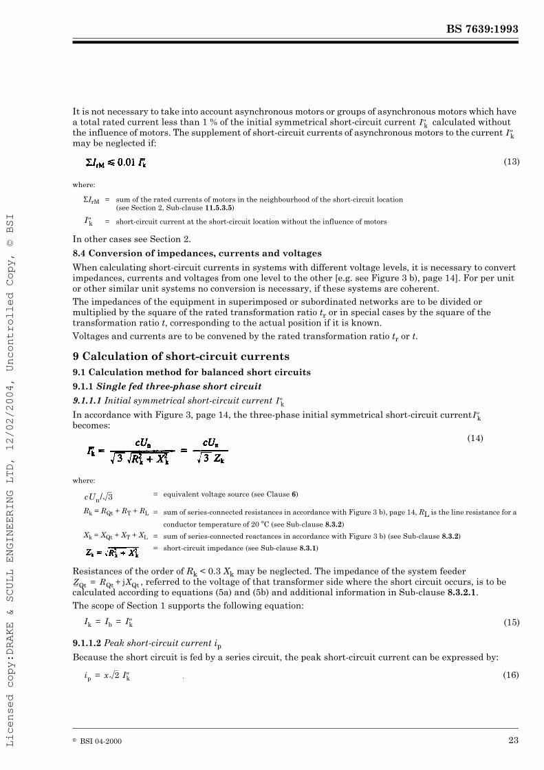
The factor x for the ratios R/X and X/R is taken from Figure 8.The factor x may also be calculated by the approximate equation:
9.1.2 Three-phase short circuit fed from non-meshed sources
9.1.2.1 Initial symmetrical short-circuit current
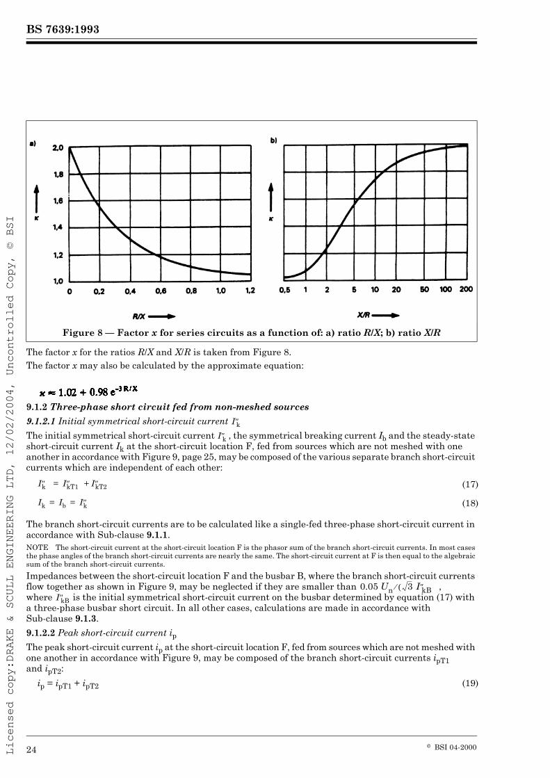
The initial symmetrical short-circuit current , the symmetrical breaking current Ib and the steady-state short-circuit current Ik at the short-circuit location F, fed from sources which are not meshed with one another in accordance with Figure 9, page 25, may be composed of the various separate branch short-circuit currents which are independent of each other:
The branch short-circuit currents are to be calculated like a single-fed three-phase short-circuit current in accordance with Sub-clause 9.1.1.NOTE The short-circuit current at the short-circuit location F is the phasor sum of the branch short-circuit currents. In most cases the phase angles of the branch short-circuit currents are nearly the same. The short-circuit current at F is then equal to the algebraic sum of the branch short-circuit currents.
Impedances between the short-circuit location F and the busbar B, where the branch short-circuit currents flow together as shown in Figure 9, may be neglected if they are smaller than , where is the initial symmetrical short-circuit current on the busbar determined by equation (17) with a three-phase busbar short circuit. In all other cases, calculations are made in accordance with Sub-clause 9.1.3.
9.1.2.2 Peak short-circuit current ipThe peak short-circuit current ip at the short-circuit location F, fed from sources which are not meshed with one another in accordance with Figure 9, may be composed of the branch short-circuit currents ipT1 and ipT2:
Figure 8 — Factor x for series circuits as a function of: a) ratio R/X; b) ratio X/R
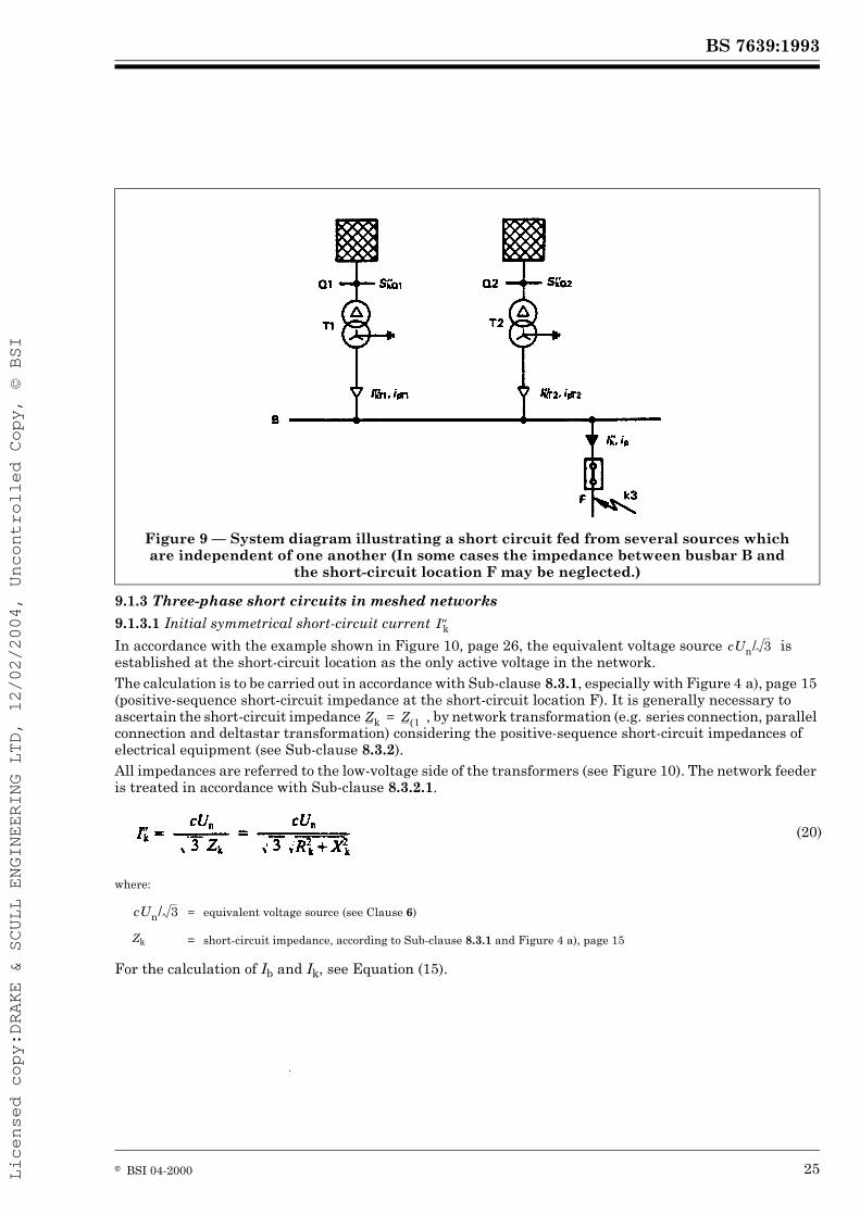
9.1.3 Three-phase short circuits in meshed networks
9.1.3.1 Initial symmetrical short-circuit current
In accordance with the example shown in Figure 10, page 26, the equivalent voltage source is established at the short-circuit location as the only active voltage in the network.The calculation is to be carried out in accordance with Sub-clause 8.3.1, especially with Figure 4 a), page 15 (positive-sequence short-circuit impedance at the short-circuit location F). It is generally necessary to ascertain the short-circuit impedance , by network transformation (e.g. series connection, parallel connection and deltastar transformation) considering the positive-sequence short-circuit impedances of electrical equipment (see Sub-clause 8.3.2).All impedances are referred to the low-voltage side of the transformers (see Figure 10). The network feeder is treated in accordance with Sub-clause 8.3.2.1.
where:
For the calculation of Ib and Ik, see Equation (15).
Figure 9 — System diagram illustrating a short circuit fed from several sources which are independent of one another (In some cases the impedance between busbar B and
the short-circuit location F may be neglected.)
(20)
= equivalent voltage source (see Clause 6)
Zk = short-circuit impedance, according to Sub-clause 8.3.1 and Figure 4 a), page 15
9.1.3.2 Peak short-circuit current ipFor the calculation of the peak short-circuit current ip in meshed networks Equation (16) is used and one of the following approximations A, B, or C is chosen to find a suitable value for x. If high accuracy is not needed, the Method A is sufficient.Method A — Uniform ratio R/X or X/R: use x = xa.The factor xa is determined from Figure 8, page 24, taking the smallest ratio of R/X or the largest ratio X/R of all branches of the network.
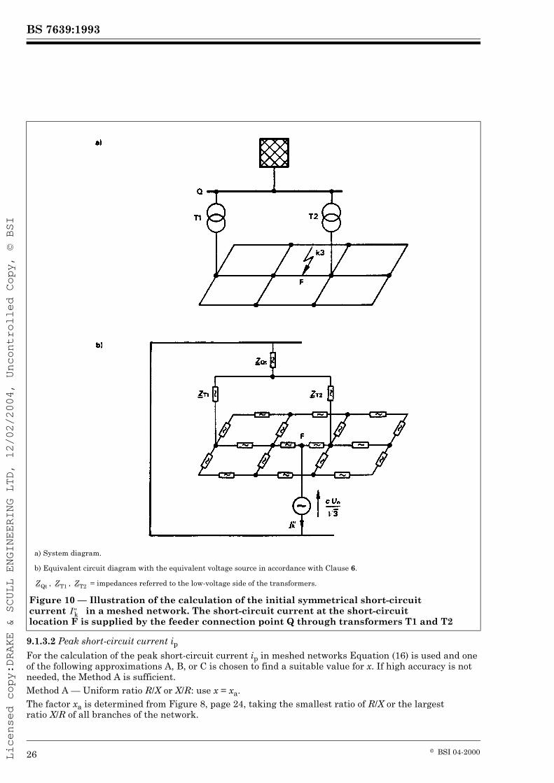
a) System diagram.
b) Equivalent circuit diagram with the equivalent voltage source in accordance with Clause 6.
, , = impedances referred to the low-voltage side of the transformers.
Figure 10 — Illustration of the calculation of the initial symmetrical short-circuit current in a meshed network. The short-circuit current at the short-circuit location F is supplied by the feeder connection point Q through transformers T1 and T2
It is only necessary to choose the branches which together carry 80 % of the current at the nominal voltage corresponding to the short-circuit location. Any branch may be a series combination of several elements.In low-voltage networks the value xa is limited to 1.8.Method B — Ratio R/X or X/R at the short-circuit location:The factor x is given by:
where 1.15 is a safety factor to cover inaccuracies caused by using the ratio R/X from a meshed network reduction with complex impedances.The factor xb is found from Figure 8 for the ratio R/X given by the short-circuit impedance at the short-circuit location F, calculated with the frequency f = 50 Hz or f = 60 Hz.In low-voltage networks the product 1.15 xb is limited to 1.8 and in high-voltage networks to 2.0.Method C — Equivalent frequency fc: use x = xc.The factor xc is found from Figure 8 for the ratio
where:
The equivalent impedance is the impedance as seen from the short-circuit location if an equivalent voltage source with the frequency fc = 20 Hz (for a nominal frequency 50 Hz) or 24 Hz (for a nominal frequency 60 Hz) is applied there as the only active voltage.
9.2 Calculation method for line-to-line and line-to-earth short circuits
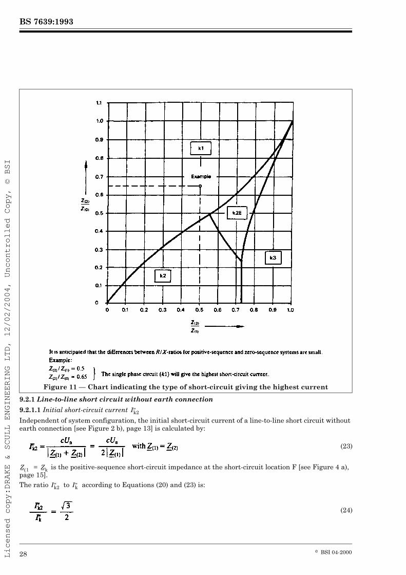
The types of short circuit considered are given in Figure 2 b) to Figure 2 d), page 13.Figure 11, page 28, shows which type of short circuit leads to the highest short-circuit currents if the a.c. component decays, i.e. if Z(2)/Z(1) < 1 (see Section 2).In Section 1 Z(2)/Z(1) = 1 is valid.
x = 1.15 xb (21)
(22a)
(22b)
= Rc + jXc
Rc = Re { } s R at power frequencyEquivalent effective resistance for the equivalent frequency fc as seen from the short-circuit location
Xc = lm { } s X at power frequencyEquivalent effective resistance for the equivalent frequency fc as seen from the short-circuit location
9.2.1 Line-to-line short circuit without earth connection
9.2.1.1 Initial short-circuit current
Independent of system configuration, the initial short-circuit current of a line-to-line short circuit without earth connection [see Figure 2 b), page 13] is calculated by:
is the positive-sequence short-circuit impedance at the short-circuit location F [see Figure 4 a), page 15].The ratio to according to Equations (20) and (23) is:
Figure 11 — Chart indicating the type of short-circuit giving the highest current
In the case of a far-from-generator short circuit, the steady-state short-circuit current Ik2 and the short-circuit breaking current Ib2 are equal to the initial short-circuit current :
9.2.1.2 Peak short-circuit current ip2
The peak short-circuit current can be expressed by:
The factor x is calculated according to Sub-clause 9.1.1.2 or 9.1.3.2 depending on the system configuration. The same value as used in the case of a three-phase short circuit may be taken.
9.2.2 Line-to-line short circuit with earth connection
9.2.2.1 Initial short-circuit currents and
According to Figure 2 c), page 13, one has to distinguish between the currents and .To calculate the value of , the following formulae are given:
with and are given in Sub-clause 8.2, Equation (4).
The initial short-circuit current , flowing to earth and/or grounded wires according to Figure 2 c), page 13, is calculated by:
9.2.2.2 Peak short-circuit current ip2E
It is not necessary to calculate ip2E because either:ip3 U ip2E or ip1 U ip2E.
9.2.3 Line-to-earth short circuit
9.2.3.1 Initial short-circuit current The initial short-circuit current of a line-to-earth short circuit according to Figure 2 d), page 13, is calculated by:
In the case of a far-from-generator short circuit, the steady-state short-circuit current Ik1 and the breaking current Ib1 are equal to the initial short-circuit current [see also Equations (15) and (25)]:
The peak short-circuit current can be expressed by:
The factor x is calculated according to Sub-clauses 9.1.1.2 or 9.1.3.2 depending on the system configuration. For simplification, the same value as used in the case of a three-phase short circuit may be taken.
9.3 The minimum short-circuit currents
9.3.1 General
When calculating minimum short-circuit currents, it is necessary to introduce the following conditions:— voltage factor c for the calculation of minimum short-circuit current according to Table I;— choose the system configuration and, in some cases, the minimum contribution from sources and network feeders, which lead to a minimum value of short-circuit current at the short-circuit location;— motors are to be neglected;
resistances RL of lines (overhead lines and cables, phase conductors and neutral conductors) are to be introduced at a higher temperature:
where RL20 is the resistance at a temperature of 20 °C and Úe in °C the conductor temperature at the end of the short circuit. The factor 0.004/°C is valid for copper, aluminium and aluminium alloy.For lines in low-voltage systems it is sufficient to take Fe = 80 °C.9.3.2 Initial symmetrical short-circuit current When calculating three-phase short-circuit currents according to Sub-clause 9.1, the minimum initial short-circuit current is given by:
is the short-circuit impedance under the conditions of Sub-clause 9.3.1.The value of the voltage factor c depends on many influences, for example operational voltage of cables or overhead lines, location of short circuit. If there are no national standards, the values of Table I may be used.When calculating unbalanced short circuits according to Sub-clause 9.2, the equivalent voltage source and impedances and under the conditions of Sub-clause 9.3.1 are chosen.
Section 2. Systems with short-circuit currents having decaying a.c. components (near-to-generator short circuits)
10 GeneralThis section gives procedures for calculations in systems with short-circuit currents having decaying a.c. components. The influence of motors is also taken into account.Procedures for the calculation of short-circuit currents of synchronous and asynchronous motors are given if their contribution is higher than 5 % of the initial symmetrical short-circuit current without motors (see Sub-clause 13.2.1).
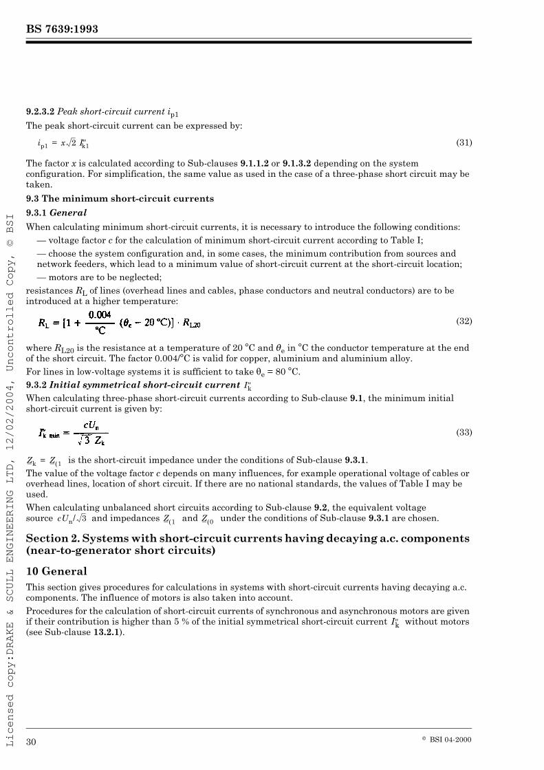
In the calculation of the short-circuit currents in systems supplied by generators, power-station units and motors (near-to-generator short circuits), it is of interest not only to know the initial symmetrical short-circuit current and the peak short-circuit current ip, but also the symmetrical short-circuit breaking current Ib and the steady-state short-circuit current Ik.In general the symmetrical short-circuit breaking current Ib is smaller than the initial symmetrical short-circuit current . Normally the steady-state short-circuit current Ik is smaller than the symmetrical short-circuit breaking current Ib.Frequently, especially when dealing with the mechanical effects of short-circuit currents, it will be necessary to determine the asymmetrical short-circuit breaking current from the a.c. breaking current and the superimposed d.c. breaking current. The decaying aperiodic component iDC can be calculated according to Clause 5.In the case of a near-to-generator short circuit the prospective short-circuit current can be considered as the sum of the following two components:
— the a.c. component with decaying amplitude during the short circuit,— the aperiodic component beginning with an initial value A and decaying to zero.
In a near-to-generator short circuit, the short-circuit current behaves generally as shown in Figure 12, page 31. In some special cases it could happen that the decaying short-circuit current reaches zero for the first time, some periods after the short circuit took place. This is possible if the d.c. time constant of a synchronous machine is larger than the subtransient time constant. This phenomenon is not dealt with in detail by short-circuit currents calculated in this standard.
= initial symmetrical short-circuit current
ip = peak short-circuit currentIk = steady-state short-circuit currentiDC = decaying (aperiodic) component of short-circuit currentA = initial value of the aperiodic component iDC
Figure 12 — Short-circuit current of a near-to-generator short circuit (schematic diagram)
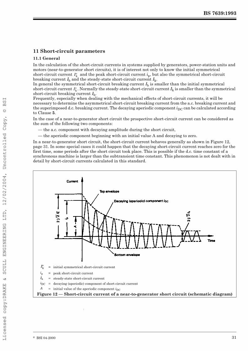
Short-circuit currents may have one or more sources as shown in Figure 13, page 32. The figure also specifies which clause of this section describes the short-circuit current calculation. The main sub-clauses for the calculation of the three-phase short-circuit currents are:
a) Singled fed short circuit. b) Short circuit fed from non-meshed sources.
Calculation according to Sub-clauses 12.2.1, 12.2.2, 12.3 and 12.4.
Calculation according to Sub-clauses 12.2.3, 12.3 and 12.4.
c) Short circuit fed from several sources with the common impedance .
d) Short circuit in meshed networks.
Calculation according to Sub-clauses 12.2.3, 12.2.4, 12.3 and 12.4.
Calculation according to Sub-clauses 12.2.4, 12.3 and 12.4.
Z can be neglected if
Z < 0.05
is calculated according to Figure 13 b)1) Generators and motors can also be connected without transformers.
Figure 13 — Various short-circuit source connections
— 12.2.1: for the case shown in Item 1) of Figure 13 a)single fed three-phase short-circuit,
— 12.2.2: for the case shown in Item 2) of Figure 13 a)
11.4 Equivalent voltage source at the short-circuit location
It is possible in all cases to determine the short-circuit current at the short-circuit location F by means of an equivalent voltage source , if correction factors are introduced for the impedances of generators and for the impedances of generators and transformers of power-station units (see Sub-clauses 11.5.3.6, 11.5.3.7, 11.5.3.8 and Clause 12). Details for the equivalent voltage source are given in Clause 6 and Table I.In this method the equivalent voltage source at the short-circuit location is the only active voltage of the system. The internal voltages of all synchronous and asynchronous machines are set to zero. Therefore the synchronous machines are only effective with their subtransient impedances and the asynchronous motors are only effective with their impedances calculated from their locked-rotor currents.Furthermore in this method all line capacitances and parallel admittances of non-rotating loads except those of the zero-sequence system shall be neglected (see Figure 15, page 37, and Figure 20, page 42).Details for consideration of motors are given in Clause 13.
11.5 Short-circuit impedances
In addition to Sub-clause 8.3.2, impedances of generators and motors are introduced. Additional calculations are given for power-station units in Sub-clauses 11.5.3.7 and 11.5.3.8. The short-circuit impedances of network feeders, network transformers, overhead lines and cables as well as short-circuit limiting reactors are valid.
11.5.1 Short-circuit impedances at the short-circuit location F
For the calculation of the initial symmetrical short-circuit current in a near-to-generator short circuit Sub-clause 8.3.1 and Figure 4, page 15, are valid.
11.5.2 Short-circuit impedances of electrical equipment
The general considerations made in Sub-clause 8.3.2 are valid. Motors and generators are dealt with in Sub-clauses 11.5.3.5 to 11.5.3.8.
11.5.3 Calculation of short-circuit impedances of electrical equipment
11.5.3.1 Network feeders
The details given in Sub-clause 8.3.2.1 are valid, except for the special case given in Sub-clause 12.2.3.1.
11.5.3.2 Transformers
The details given in Sub-clause 8.3.2.2 are valid. Unit transformers of power-station units are excluded and dealt with in Sub-clauses 11.5.3.7 and 11.5.3.8.
11.5.3.3 Overhead lines and cables
Details given in Sub-clause 8.3.2.3 are valid.
11.5.3.4 Short-circuit current limiting reactors
Details given in Sub-clause 8.3.2.4 are valid.
11.5.3.5 Motors
When calculating three-phase initial symmetrical short-circuit currents , synchronous motors and synchronous compensators are treated as synchronous generators (see Sub-clauses 11.5.3.6, 11.5.3.7, 11.5.3.8 and 13.1).
— 12.2.3: for the cases shown in Figure 13 b), Figure 13 c) respectively, if the given inequality is fulfilled (three-phase short-circuit fed from non-meshed sources),
— 12.2.4: for the general case shown in Figure 13 d) (three-phase short circuit in meshed networks).
The impedance of asynchronous motors in the positive- and negative- sequence system can be determined by:
where:
The following may be used with sufficient accuracy:
Details for consideration or omission of asynchronous motors or groups of asynchronous motors for calculation of short-circuit currents are given in Sub-clause 13.2.1.Static converter fed drives are treated for the calculation of short-circuit currents in a similar way as asynchronous motors. The following applies for static converter fed drives:
11.5.3.6 Generators directly connected to systems
When calculating three-phase initial symmetrical short-circuit currents in systems fed directly from generators without unit transformers, for example in industrial networks or in low-voltage networks, the following impedance has to be used in the positive-sequence system:
with the correction factor:
where:
(34)
UrM = rated voltage of the motorIrM = rated current of the motorSrM = rated apparent power of the motor SrM = PrM/(½r cos Îr)ILR/IrM = ratio of the locked-rotor current (Sub-clause 3.11) to the rated current of the motor
RM/XM = 0.10, with XM = 0.995 ZM for high-voltage motors with powers PrM per pair of poles W 1 MW,
RM/XM = 0.15, with XM = 0.989 ZM for high-voltage motors with powers PrM per pair of poles < 1 MW,
RM/XM = 0.42, with XM = 0.922 ZM for low-voltage motor groups with connection cables.
ZM = as in Equation (34)
UrM = rated voltage of the static converter transformer on the network side or rated voltage of the static converter, if no transformer is present
IrM = rated current of the static converter transformer on the network side or rated current of the static converter, if no transformer is present
ILR/IrM = 3
RM/XM = 0.10 with XM = 0.995 ZM
(35)
(36)
cmax = voltage factor according to Table IUn = nominal voltage of the systemUrG = rated voltage of the generator
= corrected impedance of the generator
= impedance of the generator ( )
= subtransient reactance of the generator referred to rated impedance ( )
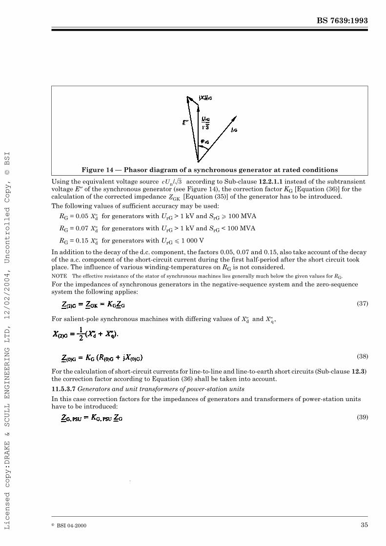
Using the equivalent voltage source according to Sub-clause 12.2.1.1 instead of the subtransient voltage E¾ of the synchronous generator (see Figure 14), the correction factor KG [Equation (36)] for the calculation of the corrected impedance [Equation (35)] of the generator has to be introduced.The following values of sufficient accuracy may be used:
RG = 0.05 for generators with UrG > 1 kV and SrG W 100 MVA
RG = 0.07 for generators with UrG > 1 kV and SrG < 100 MVA
RG = 0.15 for generators with UrG u 1 000 V
In addition to the decay of the d.c. component, the factors 0.05, 0.07 and 0.15, also take account of the decay of the a.c. component of the short-circuit current during the first half-period after the short circuit took place. The influence of various winding-temperatures on RG is not considered.NOTE The effective resistance of the stator of synchronous machines lies generally much below the given values for RG.
For the impedances of synchronous generators in the negative-sequence system and the zero-sequence system the following applies:
For salient-pole synchronous machines with differing values of and ,
For the calculation of short-circuit currents for line-to-line and line-to-earth short circuits (Sub-clause 12.3) the correction factor according to Equation (36) shall be taken into account.
11.5.3.7 Generators and unit transformers of power-station units
In this case correction factors for the impedances of generators and transformers of power-station units have to be introduced:
Figure 14 — Phasor diagram of a synchronous generator at rated conditions
If necessary the impedances and are converted by the fictitious transformation ratio tf to the high-voltage side (see Sub-clause 12.2.2).For the calculation of short-circuit currents at short circuits between generator and unit transformer of a power-station unit the equivalent voltage source at the short-circuit location is to be introduced. In this case the rated voltage of the generator is chosen, because the nominal system voltage cannot be determined. These cases are dealt with in Sub-clause 12.2.3.1.NOTE 1 Equations (40) and (42) are valid if UQ = UnQ and UG = UrG. Special considerations are recommended if for a power-station unit having a transformer with a tap changer the operational voltage UQmin is permanently higher than UnQ (UQmin > UnQ), and/or UG differs from UrG (UG > UrG) or for a power-station unit having a transformer without a tap changer the voltage UG of the generator is permanently higher than UrG (UG > UrG).NOTE 2 Values for correction factors for negative-sequence impedances and zero-sequence impedances at unbalanced short circuits are under consideration.
11.5.3.8 Power-station units
For the calculation of short-circuit currents of power-station units for short circuits on the high-voltage side it is not necessary to deal with the correction factors according to Sub-clause 11.5.3.7. In this case the following formula for the correction of the impedance of the whole power-station unit (PSU) is used:
with the correction factor:
where:
NOTE 1 Equation (44) is valid if UQ = UnQ and UG = UrG. Special considerations are recommended if for a power-station unit having a transformer with a tap changer the operational voltage UQmin is permanently higher than UnQ (UQmin > UnQ), and/or UG differs from UrG (UG > UrG) or for a power-station unit having a transformer without a tap changer the voltage UG of the generator is permanently higher than UrG (UG > UrG).NOTE 2 Values for correction factors for negative-sequence impedances and zero-sequence impedances at unbalanced short circuits are under consideration.
(40)
(41)
KT, PSU = cmax (42)
; = corrected impedances of generators (G) and unit transformers (T) of power-station units
= impedance of the generator (see Sub-clause 11.5.3.6)
= impedance of the unit transformer related to the low-voltage side (see Sub-clause 8.3.2.2)
, ÎrG = (see Sub-clause 11.5.3.6)
(43)
(44)
= corrected impedance of power-station unit related to the high-voltage side
= impedance of the generator (see Sub-clause 11.5.3.6)
= impedance of the unit transformer related to the high-voltage side (see Sub-clause 8.3.2.2)
UnQ = nominal system voltage at the connection point Q of the power-station unittr = rated transformation ratio at which the tap-changer is in the main positiontf = fictitious transformation ratio tf = Un/UrG = UnQ/UrG
11.6 Conversion of impedances, currents and voltages
The details given in Sub-clause 8.4 remain valid. Exceptions in the Sub-clauses 12.2.2.1 and 12.2.3.1 are to be regarded.
12 Calculation of short-circuit currents12.1 General
For the calculation of the initial symmetrical short-circuit current ,the symmetrical short-circuit breaking current Ib and the steady-state short-circuit current Ik at the short-circuit location, the system may be converted by transformations into an equivalent short-circuit impedance . This procedure is not allowed when calculating the peak short-circuit current ip. In this case it is necessary to distinguish between systems with and without parallel branches (see Sub-clauses 9.1.1.2, 9.1.2.2 and 9.1.3.2).
12.2 Calculation method for balanced short circuits
12.2.1 Short circuit fed from one generator
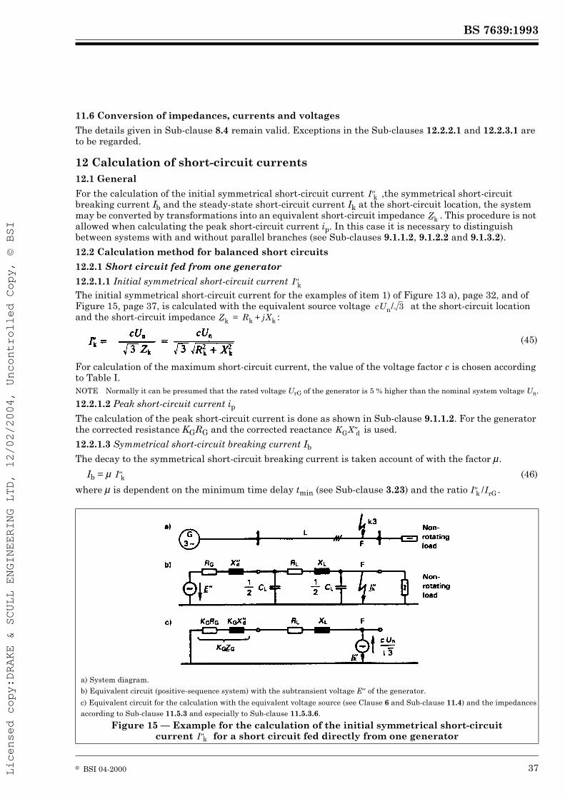
12.2.1.1 Initial symmetrical short-circuit current The initial symmetrical short-circuit current for the examples of item 1) of Figure 13 a), page 32, and of Figure 15, page 37, is calculated with the equivalent source voltage at the short-circuit location and the short-circuit impedance :
For calculation of the maximum short-circuit current, the value of the voltage factor c is chosen according to Table I.NOTE Normally it can be presumed that the rated voltage UrG of the generator is 5 % higher than the nominal system voltage Un.
12.2.1.2 Peak short-circuit current ipThe calculation of the peak short-circuit current is done as shown in Sub-clause 9.1.1.2. For the generator the corrected resistance KGRG and the corrected reactance is used.
12.2.1.3 Symmetrical short-circuit breaking current Ib
The decay to the symmetrical short-circuit breaking current is taken account of with the factor È.
where È is dependent on the minimum time delay tmin (see Sub-clause 3.23) and the ratio .
(45)
Ib = È (46)
a) System diagram.b) Equivalent circuit (positive-sequence system) with the subtransient voltage E¾ of the generator.
c) Equivalent circuit for the calculation with the equivalent voltage source (see Clause 6 and Sub-clause 11.4) and the impedances according to Sub-clause 11.5.3 and especially to Sub-clause 11.5.3.6.
Figure 15 — Example for the calculation of the initial symmetrical short-circuit current for a short circuit fed directly from one generator
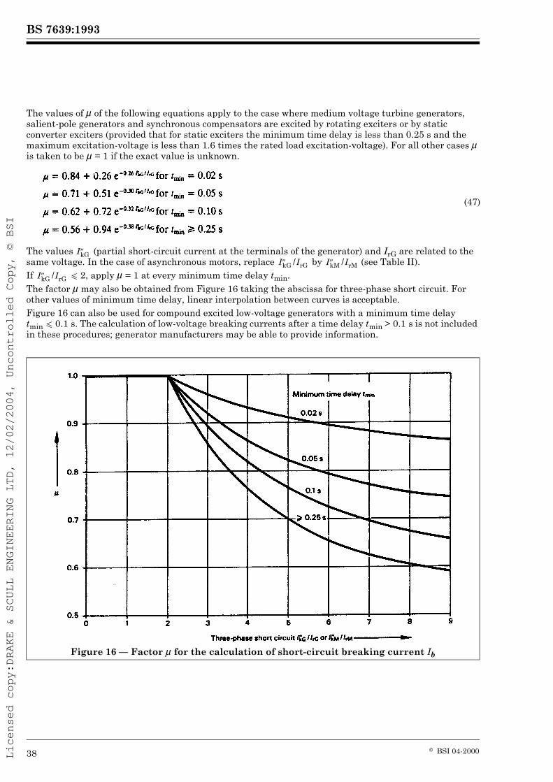
The values of È of the following equations apply to the case where medium voltage turbine generators, salient-pole generators and synchronous compensators are excited by rotating exciters or by static converter exciters (provided that for static exciters the minimum time delay is less than 0.25 s and the maximum excitation-voltage is less than 1.6 times the rated load excitation-voltage). For all other cases È is taken to be È = 1 if the exact value is unknown.
The values (partial short-circuit current at the terminals of the generator) and IrG are related to the same voltage. In the case of asynchronous motors, replace by (see Table II).If u 2, apply È = 1 at every minimum time delay tmin.The factor È may also be obtained from Figure 16 taking the abscissa for three-phase short circuit. For other values of minimum time delay, linear interpolation between curves is acceptable.Figure 16 can also be used for compound excited low-voltage generators with a minimum time delay tmin u 0.1 s. The calculation of low-voltage breaking currents after a time delay tmin > 0.1 s is not included in these procedures; generator manufacturers may be able to provide information.
(47)
I″kGI″kG /IrG I″kM /IrM
I″kG /IrG
Figure 16 — Factor È for the calculation of short-circuit breaking current Ib
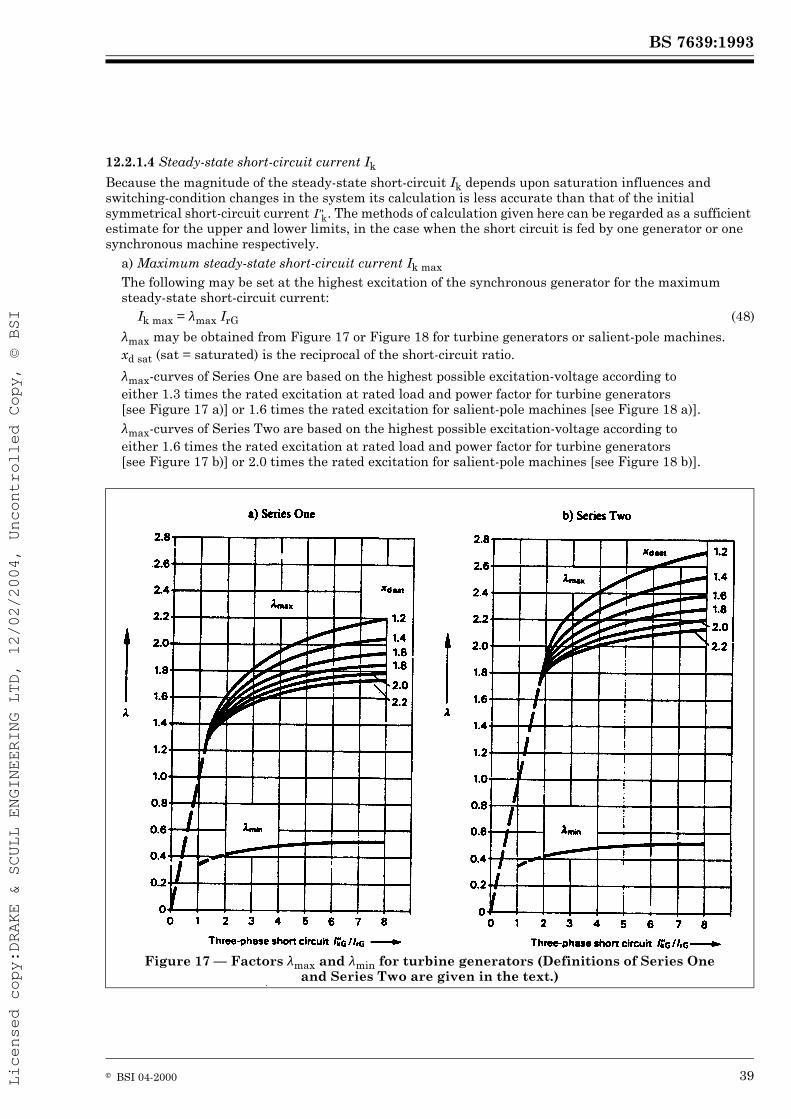
Because the magnitude of the steady-state short-circuit Ik depends upon saturation influences and switching-condition changes in the system its calculation is less accurate than that of the initial symmetrical short-circuit current . The methods of calculation given here can be regarded as a sufficient estimate for the upper and lower limits, in the case when the short circuit is fed by one generator or one synchronous machine respectively.
a) Maximum steady-state short-circuit current Ik maxThe following may be set at the highest excitation of the synchronous generator for the maximum steady-state short-circuit current:
Æmax may be obtained from Figure 17 or Figure 18 for turbine generators or salient-pole machines. xd sat (sat = saturated) is the reciprocal of the short-circuit ratio.
Æmax-curves of Series One are based on the highest possible excitation-voltage according to either 1.3 times the rated excitation at rated load and power factor for turbine generators [see Figure 17 a)] or 1.6 times the rated excitation for salient-pole machines [see Figure 18 a)].Æmax-curves of Series Two are based on the highest possible excitation-voltage according to either 1.6 times the rated excitation at rated load and power factor for turbine generators [see Figure 17 b)] or 2.0 times the rated excitation for salient-pole machines [see Figure 18 b)].
Ik max = Æmax IrG (48)
Figure 17 — Factors Æmax and Æmin for turbine generators (Definitions of Series One and Series Two are given in the text.)
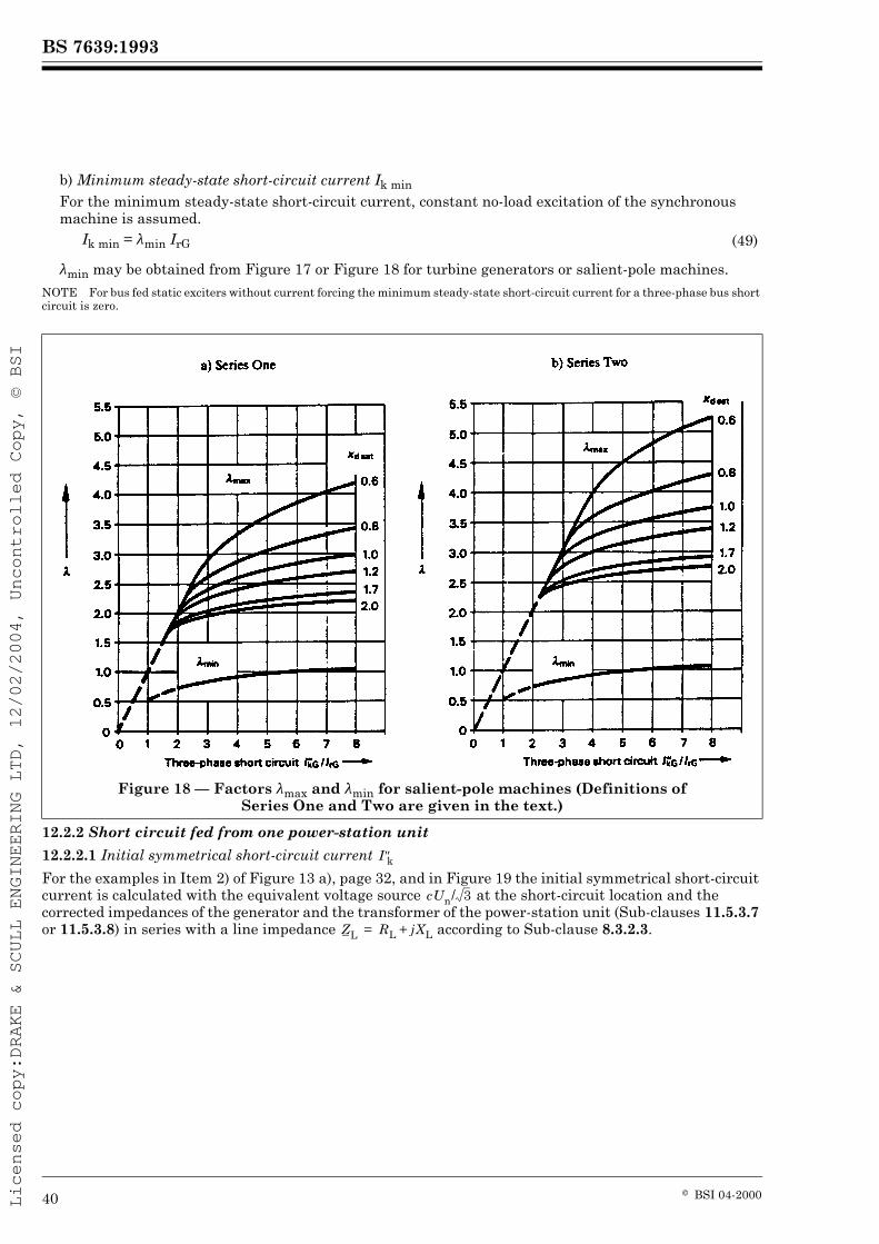
b) Minimum steady-state short-circuit current Ik minFor the minimum steady-state short-circuit current, constant no-load excitation of the synchronous machine is assumed.
Æmin may be obtained from Figure 17 or Figure 18 for turbine generators or salient-pole machines.NOTE For bus fed static exciters without current forcing the minimum steady-state short-circuit current for a three-phase bus short circuit is zero.
12.2.2 Short circuit fed from one power-station unit
12.2.2.1 Initial symmetrical short-circuit current
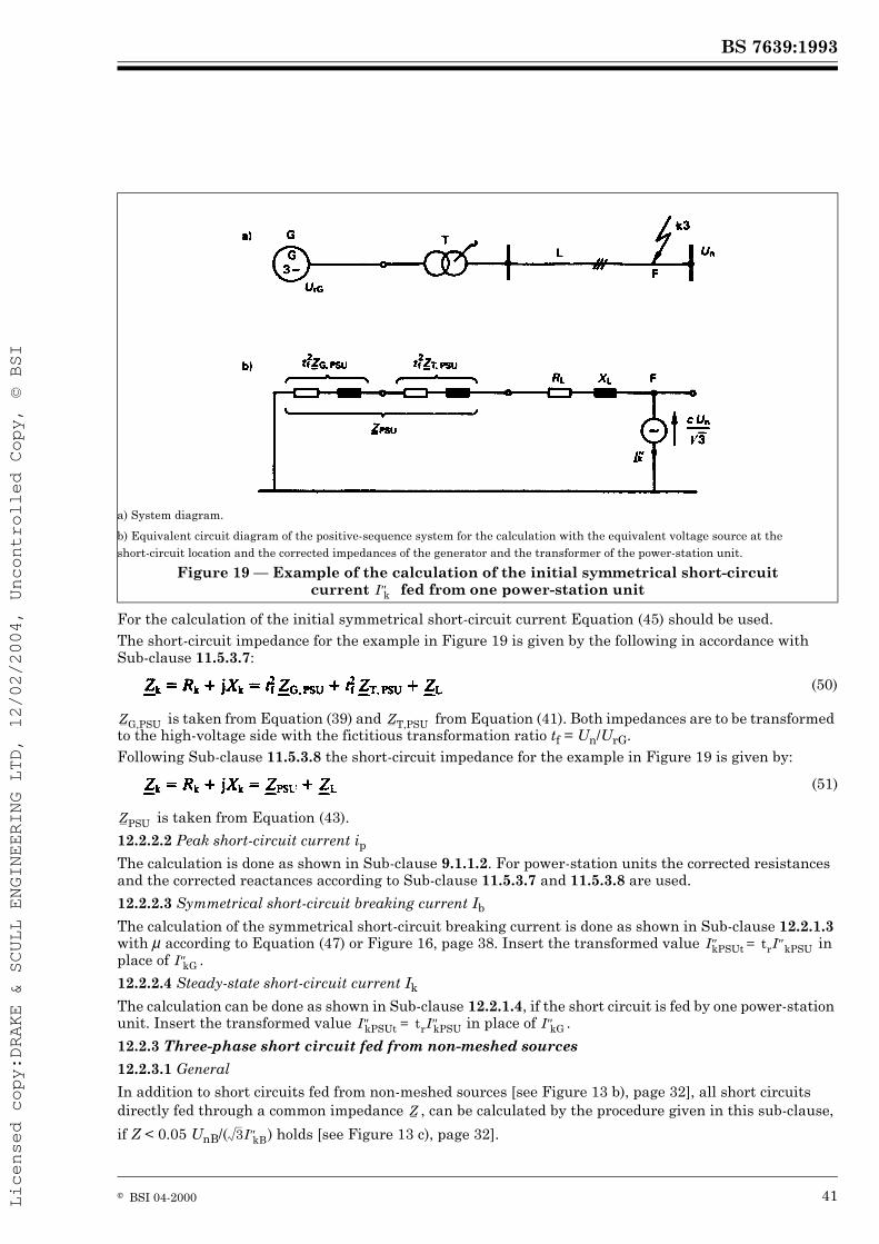
For the examples in Item 2) of Figure 13 a), page 32, and in Figure 19 the initial symmetrical short-circuit current is calculated with the equivalent voltage source at the short-circuit location and the corrected impedances of the generator and the transformer of the power-station unit (Sub-clauses 11.5.3.7 or 11.5.3.8) in series with a line impedance according to Sub-clause 8.3.2.3.
Ik min = Æmin IrG (49)
Figure 18 — Factors Æmax and Æmin for salient-pole machines (Definitions of Series One and Two are given in the text.)
For the calculation of the initial symmetrical short-circuit current Equation (45) should be used.The short-circuit impedance for the example in Figure 19 is given by the following in accordance with Sub-clause 11.5.3.7:
is taken from Equation (39) and from Equation (41). Both impedances are to be transformed to the high-voltage side with the fictitious transformation ratio tf = Un/UrG.Following Sub-clause 11.5.3.8 the short-circuit impedance for the example in Figure 19 is given by:
is taken from Equation (43).
12.2.2.2 Peak short-circuit current ipThe calculation is done as shown in Sub-clause 9.1.1.2. For power-station units the corrected resistances and the corrected reactances according to Sub-clause 11.5.3.7 and 11.5.3.8 are used.
12.2.2.3 Symmetrical short-circuit breaking current Ib
The calculation of the symmetrical short-circuit breaking current is done as shown in Sub-clause 12.2.1.3 with È according to Equation (47) or Figure 16, page 38. Insert the transformed value in place of .
12.2.2.4 Steady-state short-circuit current Ik
The calculation can be done as shown in Sub-clause 12.2.1.4, if the short circuit is fed by one power-station unit. Insert the transformed value in place of .
12.2.3 Three-phase short circuit fed from non-meshed sources
12.2.3.1 General
In addition to short circuits fed from non-meshed sources [see Figure 13 b), page 32], all short circuits directly fed through a common impedance , can be calculated by the procedure given in this sub-clause,
if Z < 0.05 UnB/( ) holds [see Figure 13 c), page 32].
a) System diagram.
b) Equivalent circuit diagram of the positive-sequence system for the calculation with the equivalent voltage source at the short-circuit location and the corrected impedances of the generator and the transformer of the power-station unit.
Figure 19 — Example of the calculation of the initial symmetrical short-circuit current fed from one power-station unit
In general the equivalent voltage source is introduced [see Figure 20 c)] at the short-circuit location. Un is the nominal voltage of the system in which the short circuit occurs. Generators, feeding the short circuit directly (without transformers) are to be treated as given in Sub-clause 11.5.3.6, power-station units according to Sub-clauses 11.5.3.7 or 11.5.3.8 and 12.2.2 and asynchronous motors as shown in Sub-clause 11.5.3.5, taking into account Clause 13.
a) System diagram.
b) Equivalent circuit diagram of the positive-sequence system with the subtransient voltages E¾.c) Equivalent circuit diagram of the positive-sequence system for the calculation with the equivalent voltage source at the short-circuit location.
Figure 20 — Example of the calculation of the initial symmetrical short-circuit current fed from non-meshed sources
For calculating, the partial, short-circuit currents and at a short circuit in F1 in Figure 21, the initial symmetrical short-circuit currents are given by:
where:
For the maximum possible value expected during the life time of the power station is to be introduced.For the calculation of the short-circuit current at the short-circuit location F2, for example at the connection to the high-voltage side of the auxiliary transformer AT in Figure 21, it is sufficient to take:
The short-circuit current at the short-circuit location F3 has to be treated according to Sub-clause 12.2.4.1.
Figure 21 — Short-circuit currents and partial short-circuit currents for three-phase short circuits between generator and transformer of a power-station unit and at the
12.2.3.2 Initial symmetrical short-circuit current
The initial symmetrical short-circuit current at the short-circuit location F can be calculated from the sum of the partial short-circuit currents as shown in Figure 22. Motors are taken into account by the application of Clause 13.
A simpler result, to be on the safe side, is gained by using the algebraic sum of values instead of the geometric sum.
12.2.3.3 Peak short-circuit current ip, symmetrical short-circuit breaking current Ib and steady-state short-circuit current Ik
If the three-phase short circuit is fed from several non-meshed sources according to Figure 22 the components of the peak short-circuit current ip and the symmetrical short-circuit breaking current Ib at the short-circuit location F are added:
The simple formulae (57) and (58) give results which are on the safe side.The partial short-circuit currents should be calculated as follows:
— network feeders according to Sub-clause 8.3.2.1,— generators without transformers between the generator and the short-circuit location as in Sub-clause 12.2.1,— power-station units as in Sub-clause 12.2.2, taking into account Sub-clauses 11.5.3.7 and 11.5.3.8,— motors as in Sub-clause 11.5.3.5 and Clause 13.
This directive does not apply to the steady-state short-circuit current Ik. It is assumed that generators fall out of step and produce a steady-state short-circuit current IkG . IbG or IkPSU . IbPSU. For network feeders is valid. There is no motor supplement to the three-phase steady-state short-circuit current (see Table II).
(55)
Figure 22 — Explanation of the calculation of , ip, Ib and Ik for a three-phase short circuit fed from non-meshed sources according to equations (55) to (58)
12.2.4 Three-phase short circuit in meshed networks
12.2.4.1 Initial symmetrical short-circuit current
The initial symmetrical short-circuit current is calculated with the equivalent voltage source at the short-circuit location. Equation (45) is used. The impedances of electrical equipment are calculated according to Sub-clause 11.5.3 (see also Sub-clause 12.2.2). For the calculation of the partial short-circuit current in Figure 21, page 43 (short-circuit location F3), it is permitted to take from Equation (54) and to transform this impedance by .The impedances in systems connected beyond transformers to the system in which the short circuit occurs have to be transformed by the square of the rated transformation ratio. If there are several transformers with slightly differing rated transformation ratios tr1, tr2, ... trn, between two systems, the arithmetic mean value can be used.Figure 13 d), page 32, and Figure 23 show examples for meshed networks with several sources.
a) System diagram.
b) Equivalent circuit diagram for the calculation with the equivalent voltage source at the short-circuit location.
* Impedance of a motor or an equivalent motor of a motor group.
Figure 23 — Example of the calculation of the initial symmetrical short-circuit current in a meshed network fed from several sources
12.2.4.2 Peak short-circuit current ipThe calculation can be done as given in Sub-clause 9.1.3.2.
12.2.4.3 Symmetrical short-circuit breaking current Ib
The following may be set for the short-circuit breaking current in meshed networks:
Currents calculated with Equation (59) are larger than the real symmetrical short-circuit breaking currents.NOTE A more accurate calculation can be done with the following equations:
where:
The values of Equations (61) and (62) are related to the same voltage.
12.2.4.4 Steady-state short-circuit current Ik
The steady-state short-circuit current Ik may be calculated by:
is the initial symmetrical short-circuit current calculated without motors.
12.3 Calculation method for line-to-line and line-to earth short circuits
The details given in Sub-clause 9.2 remain valid.
12.4 The minimum short-circuit currents
12.4.1 General
The details given in Sub-clause 9.3 remain valid. In addition, consider Sub-clauses 12.4.2 to 12.4.4. Careful reflection is necessary for the impedance correction factors in the equations (36), (40), (42) and (44), especially in the case of underexcited operation.
(59)
(60)
(61)
(62)
= equivalent voltage source at the short-circuit location
= initial symmetrical short-circuit current, symmetrical short-circuit breaking current with influence of all network feeders, synchronous machines and asynchronous motors= initial voltage difference at the connection points of the synchronous machine i and the asynchronous motor j
= parts of the initial symmetrical short-circuit current of the synchronous machine i and the asynchronous motor j
È = (see Sub-clause 12.2.1.3 and Figure 16, page 38) with or respectively
q = (see Sub-clause 13.2.1 and Figure 25, page 49)
If a short circuit is fed from one generator as shown in Figure 15, page 37, apply Sub-clause 12.2.1 and introduce a voltage factor cmin according to Table I for the calculation of the minimum short-circuit current.This procedure is also applied for short circuits, which are fed by several similar generators, operated at one point in parallel.
12.4.2.2 Short circuit in meshed networks
For the calculation use Sub-clause 12.2.4 and a voltage factor cmin according to Table I.
12.4.3 Steady-state short-circuit current Ik min fed from generators with compound excitation
The calculation for the minimum steady-state short-circuit current in a near-to-generator short circuit, fed by one or several similar and parallel working generators with compound excitation, is done as follows:
For the effective reactance of the generators introduce:
Ikp is the steady-state short-circuit current of a generator with a three-phase terminal short circuit.This value IkP should be obtained from the manufacturer.
12.4.4 Initial short-circuit currents at unbalanced short circuits
The initial short-circuit currents at unbalanced short circuits are calculated according to Sub-clauses 9.2 and 12.3. Use the voltage factor cmin according to Table I.
13 Influence of motors13.1 Synchronous motors and synchronous compensators
When calculating the initial symmetrical short-circuit current , the peak short-circuit current ip, the symmetrical short-circuit breaking current Ib and the steady-state short-circuit current Ik, the synchronous motors and synchronous compensators are treated in the same way as synchronous generators.Exceptions are: no modification for internal voltage; motors may have constant field voltage and no regulators. Motors and compensators with terminal-fed static exciters do not contribute to Ik.
13.2 Asynchronous motors
13.2.1 General
High-voltage motors and low-voltage motors contribute to the initial symmetrical short-circuit current , to the peak short-circuit ip, to the symmetrical short-circuit breaking current Ib, and for unbalanced short circuits also to the steady-state short-circuit current Ik.High-voltage motors have to be considered in the calculation of short circuit. Low-voltage motors are to be taken into account in auxiliaries of power-stations and in industrial and similar installations, for example in networks of chemical and steel industries and pump-stations.Motors in low-voltage public power supply systems may be neglected.In the calculation of short-circuit currents those high-voltage and low-voltage motors may be neglected, which, according to the circuit diagram (interlocking) or to the process (reversible drives), are not switched in at the same time.
High-voltage and low-voltage, motors which are connected through two-winding transformers to the network in which the short circuit occurs, may be neglected in the calculation of currents for a short circuit at the feeder connection point Q (see Figure 24), if:
where:
The estimation according to Equation (66) is not allowed in the case of three-winding transformers.
(66)
×PrM = sum of the rated active powers of the high-voltage and the low-voltage motors which should be considered×SrT = sum of the rated apparent powers of all transformers, through which the motors are directly fed
= initial symmetrical short-circuit power at the feeder connection point Q without supplement of the motors
Figure 24 — Example for the estimation of the contribution from the asynchronous motors in relation to the total short-circuit current
The factor q for the calculation of the symmetrical short-circuit breaking current for asynchronous motors may be determined as a function of the minimum time delay tmin:
If the calculation in Equation (67) provides larger values than 1 for q, assume that q = 1. The factor q may also be obtained from Figure 25.Low-voltage motors are usually connected to the busbar by cables with different lengths and cross-sections. For simplification of the calculation, groups of motors including their connection cables may be combined to an equivalent motor, see motor M4 in Figure 24.For these equivalent asynchronous motors including their connection cables the following may be used:
Figure 25 — Factor q for the calculation of the symmetrical short-circuit breaking current of asynchronous motors
q = 1.03 + 0.12 in m for tmin = 0.02 s with m:
q = 0.79 + 0.12 in m for tmin = 0.05 s the rated active power of motors (MW)
q = 0.57 + 0.12 in m for tmin = 0.10 s per pair of poles (67)
q = 0.26 + 0.10 in m for tmin W 0.25 s
ZM = [according to Equation (34)]IrM = sum of the rated currents of all motors in a group of motors (equivalent motor)ILR/IrM= 5RM/XM = 0.42, respectively XM = 1.3
For a short circuit at the busbar B in Figure 24, page 48, the partial short-circuit current of the low-voltage motor group M4 may be neglected, if the following condition holds:
IrM4 is the rated current of the equivalent motor M4. is the initial symmetrical short-circuit current at the short-circuit location B without supplement of the equivalent motor M4.In the case of a short circuit on the high-voltage side (e.g. short-circuit locations Q or A in Figure 24) it is possible to simplify the calculation of ZM according to Equation (34) with the rated current of the transformer T3 (IrT3, LV) in Figure 24 instead of the rated current IrM4 of the equivalent motor M4.
13.2.2 Terminal short circuit of asynchronous motors
In the case of balanced and line-to-line short circuits at the terminals of asynchronous motors the currents , ip, Ib and Ik are evaluated as shown in Table II. For solid grounded systems the influence of motors on
the line-to-earth short-circuit current cannot be neglected.
13.2.3 Short circuit beyond an impedance
For the calculation of the initial short-circuit currents according to Sub-clauses 12.2.3 and 12.2.4, asynchronous motors are substituted by their impedances ZM according to Equation (34) in the positive-sequence and negative-sequence system.
Table II — Calculation of short-circuit currents of asynchronous motors in the case of a short circuit at the terminals
13.3 Static converter fed drives
Static converter fed drives (e.g. as in rolling mill drives) are considered for three-phase short circuits only, if the rotational masses of the motors and the static equipment provide reverse transfer of energy for deceleration (a transient inverter operation) at the time of short circuit. Then they contribute only to the initial symmetrical short-circuit current and to the peak short-circuit current ip. They do not contribute to the symmetrical short-circuit breaking current Ib.Apply Sub-clause 11.5.3.5 for the equivalent motor of the static converter fed drive.
(68)
Short circuit Balanced short circuit Line-to-line short circuit
Initial symmetrical short-circuit current (69) (73)
Peak short-circuit current(70) (74)
High-voltage motors:xM = 1.65 (corresponding to RM/XM = 0.15) for motor powers per pair of poles < 1 MW
xM = 1.75 (corresponding to RM/XM = 0.10) for motor powers per pair of poles W 1 MW
Low-voltage motor groups with connection cables xM = 1.3 (corresponding to RM/XM = 0.42)
Symmetrical short-circuit breaking current (71) (75)
È according to equation (47) or Figure 16, page 38, with q according to equation (67) or Figure 25, page 49
Steady-state short-circuit current Ik3M = 0 (72) (76)
14 Consideration of non-rotating loads and capacitorsCalculation methods are given in Sub-clauses 12.2 and 12.3 which allow, as stated in Clause 6, line capacitances and parallel admittances of non-rotating loads to be neglected.
14.1 Parallel capacitors
Regardless of the time of short-circuit occurrence, the discharge current of the capacitors may be neglected for the calculation of the peak short-circuit currents.
14.2 Series capacitors
The effect of capacitors in series can be neglected in the calculation of short-circuit currents, if they are equipped with voltage-limiting devices in parallel, acting if a short-circuit occurs.
Appendix A (informative) Calculation of short-circuit currentsA.1 Example 1: Calculation of short-circuit currents in a low-voltage systemA.1.1 ProblemA low-voltage system with Un = 380 V and f = 50 Hz is given in Figure A.1. The short-circuit currents , and ip shall be determined at the short-circuit locations F1 to F3 according to Section 1 (Systems with short-circuit currents having no a.c. component decay). The equipment data for the positive-sequence, negative-sequence and zero-sequence systems are given in Table A.I.
A.1.2 Determination of the positive-sequence impedancesA.1.2.1 Network feederAccording to Equation (5b) with cQ = 1.1 (see Table I) it follows that:
A.1.2.2 TransformersAccording to equation (6), (7) and (8) it follows that:Transformer T1:
Figure A.1 — Low-voltage system with short-circuit locations F1, F2 and F3. Example 1
Table A.I — Data of equipment for Example 1 and positive-sequence, negative-sequence and zero-sequence short-circuit impedances
A.1.3 Determination of the zero-sequence impedancesA.1.3.1 TransformersFor the transformers T1 and T2 with the vector group Dy5 the following relations are given by the manufacturer:
Transformer T1:
Transformer T2:
A.1.3.2 Lines (cables and overhead lines)The zero-sequence impedances are to be calculated with the relations R(0)L/RL and X(0)L/XL obtained from the manufacturer.
Equipment Data of equipmentData and equation for the calculation
A.1.4 Calculation of the short-circuit currents and ip for balanced short circuits at the short-circuit locations F1, F2 and F3A.1.4.1 Short-circuit location F1Short-circuit impedance at the short-circuit location F1 according to Figure A.2:
Maximum initial symmetrical short-circuit current according to Equation (20) with c = 1.05 (see Table I):
Peak short-circuit current ip according to Sub-clause 9.1.3.2. Because the calculation of is carried out with complex values, it is sufficient to choose the conservative Method B or for higher accuracy Method C of Sub-clause 9.1.3.2.
— Line L2: R(0)L = 4.23 RL; X(0)L = 1.21 XL with return circuit by sheath:
— Line L3: R(0)L = 3 RL; X(0)L = 4.46 XL with return circuit by the fourth conductor, sheath and earth:
— Line L4: Overhead line with R(0)L = 2 RL; X(0)L = 3 XL, when calculating the maximum short-circuit currents:
Figure A.2 — Positive-sequence system (according to Figure A.1, page 52) for the calculation of and ip at the short-circuit location F1
Method B [impedance ratio at the short-circuit location, Equation (21)]:From the short-circuit impedance the ratio Rk/Xk = 1.857 m7/6.771 m7 = 0.274 can be found and with the equation for x in Sub-clause 9.1.1.2 it follows that:
Method C [equivalent frequency fc, Equation (16) with R/X according to Equation (22a)]:The impedance is calculated according to the comments of Method C of Sub-clause 9.1.3.2 with an equivalent source voltage of the frequency fc = 20 Hz (fn= 50 Hz). The calculation procedure is similar to the calculation of , but taking the following values:
In order to interpret this result, the ratios R/X of the parallel branches and + + are to be considered. These can be calculated as:
Additionally, two-thirds of the short-circuit current are taken by the transformer T1.The breaking current Ib and the steady state short-circuit current Ik at all three short-circuit locations need not be calculated since they are equal to the corresponding initial symmetrical short-circuit current [see Equation (15)].
The peak short-circuit current can be calculated from Sub-clause 9.1.3.2:
This leads to R/X ratio of:R/X = 0.2847
Using the equation for x in Sub-clause 9.1.1.2:xc = 1.44
thus:
The decisive ratio R/X is mostly determined by those of the branches + and + with (RT1 + RL1)/(XT1 + XL1) = 0.29 and (RT2 + RL2)/(XT2 + XL2) = 0.32. Moreover, these two relations are similar to Rk/Xk = 1.953 7/6.852 7 = 0.29 F xb = 1.43.A.1.4.3 Short-circuit location F3
with:
Calculated according to Equation (21) of Method B (see Sub-clause 9.1.3.2):
A.1.5 Calculation of the short-circuit currents and ip1 for line-to-earth short circuits at the short-circuit locations F1, F2 and F3A.1.5.1 Short-circuit location F1
Short-circuit impedances:
Figure A.3 — Positive-sequence, negative-sequence and zero-sequence systems with connections at the short-circuit location F1 for the calculation at
Initial short-circuit current for a line-to-earth short circuit according to Equation (29) (see Sub-clause 9.2.3.1):
Peak short-circuit current ip1 according to Equation (31) of Sub-clause 9.2.3.2, calculated with the same value for xc in the case of a balanced three-phase short circuit (see Sub-clause 9.1.3.2 for xc):
A.1.5.2 Short-circuit location F2
A.1.5.3 Short-circuit location F3
A.1.6 Collection of resultsTable A.II — Collection of results for Example 1 (Un = 380 V)
Short-circuit locationZ(0)
a ip.c ip1.c
(m7) (m7) (kA) (kA) (kA) (kA) —
F1F2F3
7.0217.125
34.93
6.246.46
80.67
32.8132.33
6.60
67.4265.84
9.89
34.1033.41
4.59
70.0768.04
6.82
1.041.030.70
a In all cases = Ib = Ik (far-from-generator short circuit).
A.2 Example 2: Calculation of balanced short-circuit currents in a medium-voltage system, influence of motorsA.2.1 ProblemA medium-voltage system 33 kV/6 kV (50 Hz) is given in Figure A.4, page 61. The calculations are to be carried out without asynchronous motors according to Sub-clause 9.1 of Section 1 and with the influence of asynchronous motors according to Sub-clause 13.2 of Section 2.The 33-kV-/6-kV-sub-station with two transformers each of SrT = 15 MVA is fed through two three-core solid type 33-kV-cables from a network feeder with = 750 MVA and UnQ = 33 kV.As the short-circuit resistance is small in comparison with the short-circuit reactance (Rk < 0.3 Xk, see Sub-clause 9.1.1.1) it is sufficiently accurate to calculate only the short-circuit reactances of the electrical equipment and the short-circuit reactance Xk at the short-circuit location F in Figure A.4.To demonstrate the difference, when calculating the short-circuit current with absolute quantities or with quantities of a per unit system, both calculations are carried out (see Sub-clause A.2.3 for the calculation with per unit quantities). To show the difference between a real and a complex calculation and to demonstrate the decaying of the aperiodic component of the short-circuit current an additional calculation is given in Sub-clause A.2.4.A.2.2 Calculation with absolute quantitiesTable A.III demonstrates the calculation of the short-circuit reactance Xk at the short-circuit location F in Figure A.4 if the circuit breakers CB1 and CB2 are open (without influence of the asynchronous motors M1 and M2).The initial symmetrical short-circuit current without the influence of the asynchronous motors M1 and M2 becomes with c = 1.1 (according to Table I for the maximum short-circuit currents):
Table A.III — Calculation of Xk (7) for Example 2, without the influence of asynchronous motors M1 and M2 (CB1 and CB2 are open)
The initial symmetrical short-circuit current, without the influence of motors, at the short-circuit location (see Figure A.4) is:
According to Sub-clause 12.2.3 (three-phase short circuit fed from non-meshed sources and Equation (55) it is possible to add the partial symmetrical short-circuit current at the short-circuit location (see Figure A.4, page 61):
The partial short-circuit currents and (CB1 and CB2 are closed) are calculated from Equation (69) in Table II and Equation (34) in Sub-clause 11.5.3.5 for the short-circuit impedances of asynchronous motors.Motor M1:
where:
Motor M2 (three motors with equal data F equivalent motor):
No. Equipment Equations and calculations Reactance (7)
1 Network feeder Equation (5b):
0.582
2 Cable L1 0.0177
3 Transformer T1 Equation (6) (XT . ZT)
0.3969
4 L1 + T1 XL1t + XT1 = XL2t + XT2 0.4146
5 (L1 + T1) (L2 + T2) in parallel Two equal branches in parallel (XL1t + XT1) 0.2073
Partial short-circuit currents according to Equation (69):
Short-circuit current at the short-circuit location F in Figure A.4, page 61, including the influence of the motors M1 and M2:
The influence of the asynchronous motors raises the short-circuit current to 1.3 of the value without motors.
When calculating the partial short-circuit current fed from the network, Sub-clause 12.2.3.3 is used:
For the calculation of Ib3M the factor È has to be determined according to Equation (47) and q according to Equation (67) with tmin = 0.1 s. With and the values ÈM1 = 0.80 and ÈM2 = 0.72 are calculated. With active power per pair of poles mM1 = 2.5 MW and mM2 = 1 MW the values qM1 = 0.68 and qM2 = 0.57 are found.According to Equation (71) the partial breaking currents are:
The symmetrical short-circuit breaking current becomes:
According to Equation (72) there is no contribution of the asynchronous motors to Ik:
A.2.3 Calculation with per unit quantitiesFor the calculation with per unit (p.u.) quantities two reference quantities (Index R) have to be chosen. For Example 2 those quantities shall be:
Per-unit (p.u.) quantities (with an asterisk [*] as a superscript) therefore are defined as follows:
If the system is not coherent as indicated in Sub-clause 8.4, that means UrTHV/UrTLV s UnHV/UnLV, then the rated transformation ratio related to p.u. voltages becomes:
The procedure for the calculation of the initial symmetrical short-circuit current without the influence of the motors is given in Table A.IV in a similar manner as in Table A.III.The initial symmetrical short-circuit current * at the short-circuit location in Figure A.4, page 61, is:
From this the short-circuit current in kiloamperes is calculated:
Table A.IV — Calculation of *Xk (per unit [p.u.]) for Example 2, without the influence of asynchronous motors M1 and M2 (CB1 and CB2 open)
No. Equipment Equations and calculations Reactance (p.M.)
1 Network feeder Equation (5b):
0.1617
2 Cable L1
0.0491
3 Transformer T1 Equation (6) (XT . ZT)
1.1025
4 L1 + T1 1.1516
5 (L1 + T1) (L2 + T2) in parallel Two equal branches in parallel 0.5758
The short-circuit impedances in p.u. of the asynchronous motors are:
Partial short-circuit currents according to Equation (69):
The results are the same as in Sub-clause A.2.2.A.2.4 Calculation with complex quantitiesIn this Sub-clause the short-circuit calculation is done with complex quantities for the medium voltage system according to Figure A.4, page 61.The complex impedances of electrical equipment are calculated from the data given in Figure A.5. This figure indicates the partial short-circuit currents of the branches and their addition at the short-circuit location.
With a minimum time delay tmin = 0.1 s and the already calculated values for È and q:IbM1 = 0.80 · 0.68 · 2.54 kA = 1.38 kA
and corresponding for the motor M2:
Asymmetrical short-circuit breaking current Ib asym with the help of iDC:
Steady-state short-circuit current Ik according to Equation (58):
A.3 Example 3: Calculation of balanced short-circuit currents in the case of near-to-generator short circuits. Impedance correction factorA.3.1 ProblemThe balanced short-circuit currents at the short-circuit locations F1 to F4 in Figure A.6, page 72, are to be calculated according to Section 2.A power-station unit (PSU) is connected to a 220 kV system with the actual, initial short-circuit power
= 8 000 MVA of the network feeder. The auxiliary transformer AT is of the three-winding type feeding two auxiliary busbars B and C with Un = 10 kV.The influence of asynchronous motors on the short-circuit currents is to be taken into account when calculating short-circuit currents at the short-circuit locations F2, F3 and F4. Low-voltage asynchronous motors shall be handled as motor groups. The terminal short-circuit currents of the high-voltage or low-voltage motors are calculated within the Table A.VI or Table A.VII.
IbM2 = 0.72 · 0.57 · 2.24 kA = 0.92 kAIb = (14.32 + 1.38 + 0.92) kA = 16.62 kA (see Sub-clause A.2.2)
A.3.2 Short-circuit impedances of electrical equipmentA.3.2.1 Network feederAccording to Sub-clause 8.3.2.1 it follows, with c = 1.1 from the actual symmetrical short-circuit power at the feeder connection point, that:
For the calculation of the maximum short-circuit current at the short-circuit locations F2 and F3, ZQ min (corresponding to ) is found according to Sub-clause 12.2.3.1. is to be estimated from the future planning of the power-system.
A.3.2.2 Unit transformerFrom the data given in Figure A.6, page 72, Equations (6) to (8) according to Sub-clause 8.3.2.2 yield:
Converted to the low-voltage side of the unit transformer with tr = 240 kV/21 kV:
* For details see Table A.VI.** For details see Figure A.8 and Table A.VII.
Figure A.6 — Network feeder, power-station unit (PSU) — unit transformer and generator — with auxiliary transformer (AT), high-voltage and low voltage asynchronous motors, Example 3
A.3.2.3 GeneratorWith the data given in Figure A.6, the calculation according to Sub-clause 11.5.3.7 with c = 1.1 (see Table I) and RG = 0.05 (see Sub-clause 11.5.3.6) can be performed as:
The correction factor according to Sub-clause 11.5.3.7 can, be found:
therefore:
In order to calculate the short-circuit current on the high-voltage side of the transformer (F1 in Figure A.6, page 72) the equations in Sub-clause 11.5.3.8 are used with cmax = 1.1, tf = Un/UrG = 220 kV/21 kV and tr = 240 kV/21 kV, and therefore:
A.3.2.4 Auxiliary transformerThe positive-sequence short-circuit impedances , and according to Figure 7, page 22, can be determined with the equations of Sub-clause 8.3.2.2. Substituting the data presented in Figure A.6 in Equation (9), the positive-sequence short-circuit impedances of the transformer are calculated as follows (related to the 21 kV side A):
Using Equation (10) and referring the impedances to UrTA = 21 kV:
Converted to the 10.5 kV (side B or C) with tr = 21 kV/10.5 kV, the impedances of the three-winding transformer AT are:
A.3.2.5 Low-voltage transformers 2.5 MVA and 1.6 MVAAccording to Figure A.6, page 72, and Figure A.8, page 80, there are five transformers with SrT = 2.5 MVA and UrTHV/UrTLV = 10 kV/0.693 kV connected to each of the two auxiliary busbars 10 kV and in addition one transformer with SrT = 1.6 MVA, UrTHV/UrTLV = 10 kV/0.4 kV. Each of these transformers feeds a group of low-voltage asynchronous motors.With the equations in Sub-clause 8.3.2.2 and the data in Table A.VII it follows that:
Converted to the low-voltage side With tr = 10 kV/0.4 kV:
A.3.2.6 Asynchronous motorsData and calculations of the short-circuit impedances of the high-voltage motors M1 to M14 according to Sub-clauses 11.5.3.5 and 13.2 are given in Table A.VI.Using Equations (69) and (34) and bearing in mind that UrM is equal to Un in this special case, the following expression can be found for :
Data and calculation of the short-circuit impedances of the low-voltage motor groups including their supply cables according to Sub-clauses 11.5.3.5 and 13.2 are given in Figure A.8 page 80, and Table A.VII.
Table A.VI — Data of high-voltage motors and their partial short-circuit currents at the short-circuit location on busbars B or C respectively
A.3.3 Calculation of short-circuit currentsA.3.3.1 Short circuit at the short-circuit location F1The calculation is done according to Sub-clause 12.2.3. It is not necessary to take the asynchronous motors into account (see Sub-clause 13.2.1, contribution of motors smaller than 5 %).The initial symmetrical short-circuit current is calculated according to Equation (55):
1) The values for xM are given in Table II of Sub-clause 13.2.2.2) Equation (47), tmin = 0.1 s.3) Equation (67), tmin = 0.1 s.
Power-station unit (see Sub-clauses 12.2.3.3 and 12.2.2.3):
with:
A.3.3.2 Short circuit at the short-circuit location F2First of all, according to Figure 21, page 43, the initial symmetrical short-circuit current at the short-circuit location F2 (without the influence of asynchronous motors) is derived from the partial short-circuit currents [see Equation (52)] and [see Equations (53) and (41)].I″kG I″kT
Normally, there is no circuit breaker provided to switch off the total breaking current, so that only the current is of interest.The additional short-circuit currents fed from the asynchronous motors can be calculated from the results of Table A.VI and Table A.VII and from the impedances of the auxiliary transformer (see Sub-clause A.3.2.4) related to the HV-side of the transformer AT.
Figure A.7 — Positive-sequence system for the calculation of the partial short-circuit current from high-voltage and low-voltage motors at the short-circuit
location F2. Impedances are transferred to the high-voltage side of the auxiliary transformer AT with tr = 21 kV/10.5 kV = 2
Figure A.8 — Detail of Figure A.6, page 72. Transformers and groups of low-voltage asynchronous motors connected to the auxiliary busbar B. Transformers and low-voltage
motor groups connected to the busbar C are identical
Table A.VII — Data of low-voltage asynchronous motors and data of transformers 10 kV/ 0.693 kV and 10 kV/0.4 kV respectively connected to the auxiliary busbar B.
Partial short-circuit currents of the low-voltage motors at the short-circuit location F3
This partial short-circuit current has to be considered because its magnitude reaches approximately 7 % of the current as calculated before. The sum of the short-circuit current reaches:
Additionally, partial peak short-circuit currents and breaking currents fed from the asynchronous motors are to be added to the above calculated currents ip and Ib. These are with x = 1.7 as a first approach (high-voltage motors have x = 1.75 or x = 1.65, see Table A.VI, low-voltage motor groups are to be considered with x = 1.3) and as a conservative approach. Account has been taken of the fact that IbG + IbM–AT is smaller than , so that the breaking capacity for a circuit breaker between the unit transformer and the generator may be IbT = 42.30 kA. When calculating ipM–AT with Method C of Sub-clause 9.1.3.2 taking the impedances of the motors from Table A.VI and Table A.VII, the factor xc = 1.701 is found and therefore ipM–AT = 15.42 kA; that is equal to the value given above.
A.3.3.3 Short-circuit at the short-circuit location F3The initial symmetrical short-circuit current at the short-circuit location F3 can be calculated from the partial short-circuit currents as shown in Figure A.9:
Calculation of :
where:
Figure A.9 — Positive-sequence system for the calculation of at the short-circuit location F3
It follows for the short-circuit power (see Sub-clause 3.6):
The peak short-circuit current ip can be derived with the following x-factors:
with 1.15 · xAT = 2 (see Sub-clause 9.1.3.2, Method B) and the ratio R/X of the low-voltage motors including the transformers 15 to 20 according to Table A.VII.As a medium effective value is found:
If the short-circuit current is transformed to the side A of the auxiliary transformer AT it becomes obvious, that is already smaller than twice IrG, so that is valid [see Equation (18), far-from generator short circuit].
with È = 0.77 (tmin = 0.1 s) according to . 5 (see Sub-clause 13.2.1) and q . 0.342 derived from the conservative estimation that the low-voltage asynchronous motors of the motor group have rated powers u 0.3 MW and p = 2 (pair of poles).
xAT = 1.02 + 0.98 e–3 (0.0121 7/0.3438 7) = 1.90
(see Sub-clause 9.1.3.2, Method B: 1.15 · 1.9 > 2.0)
A.3.3.4 Short-circuit at the short-circuit location F4is calculated with the help of Figure A.10.
The peak short-circuit current is calculated from:
According to Method B of Sub-clause 9.1.3.2, it is necessary to take 1.15 · xb = 1.15 · 1.61 = 1.85. In this case for a low-voltage short circuit the maximum for 1.15 xb is limited to 1.8.
Figure A.10 — Positive-sequence system for the calculation of at the short-circuit location F4
(When considering the calculation of ipT20 it can be recognized that the impedance of the low-voltage transformer T20 gives the main part of the impedance , so that the ratio RT20/XT20 of the transformer will determine x for the calculation of ipT20. From the ratio RT20/XT20 = 1.031 m7/5.910 m7 = 0.174 the factor x = 1.60 can be determined and therefore for the whole peak short-circuit current at the short-circuit location F4:
National annex NA (informative) Original IEC text amended by CENELEC common modifications1 ScopeIn line 3, “230 kV” has been replaced by “380 kV”.Table I. Voltage factor cIn the last box of column 1, “230 kV” has been replaced by “380 kV”.Appendix A. Calculation of short-circuit currentsIn the title, “Appendix A” has been replaced by “Appendix A (informative)”.
National annex NB (informative) Cross-references
Publication referred to Corresponding British Standard
BS 4727 Glossary of electrotechnical power, telecommunication, electronics, lighting and colour terms
IEC 50(131):1978 Part 1:Group 01:1983 Fundamental terminology
IEC 50(151):1978 Part 1:Group 02:1980 Electrical and magnetic devices terminology
IEC 50(441):1984 Part 2:Group 06:1985 Switchgear and controlgear terminology (including fuse terminology)
BSI — British Standards InstitutionBSI is the independent national body responsible for preparing British Standards. It presents the UK view on standards in Europe and at the international level. It is incorporated by Royal Charter.
Revisions
British Standards are updated by amendment or revision. Users of British Standards should make sure that they possess the latest amendments or editions.
It is the constant aim of BSI to improve the quality of our products and services. We would be grateful if anyone finding an inaccuracy or ambiguity while using this British Standard would inform the Secretary of the technical committee responsible, the identity of which can be found on the inside front cover. Tel: 020 8996 9000. Fax: 020 8996 7400.
BSI offers members an individual updating service called PLUS which ensures that subscribers automatically receive the latest editions of standards.
Buying standards
Orders for all BSI, international and foreign standards publications should be addressed to Customer Services. Tel: 020 8996 9001. Fax: 020 8996 7001.
In response to orders for international standards, it is BSI policy to supply the BSI implementation of those that have been published as British Standards, unless otherwise requested.
Information on standards
BSI provides a wide range of information on national, European and international standards through its Library and its Technical Help to Exporters Service. Various BSI electronic information services are also available which give details on all its products and services. Contact the Information Centre. Tel: 020 8996 7111. Fax: 020 8996 7048.
Subscribing members of BSI are kept up to date with standards developments and receive substantial discounts on the purchase price of standards. For details of these and other benefits contact Membership Administration. Tel: 020 8996 7002. Fax: 020 8996 7001.
Copyright
Copyright subsists in all BSI publications. BSI also holds the copyright, in the UK, of the publications of the internationalstandardization bodies. Except as permitted under the Copyright, Designs and Patents Act 1988 no extract may be reproduced, stored in a retrieval system or transmitted in any form or by any means – electronic, photocopying, recording or otherwise – without prior written permission from BSI.
This does not preclude the free use, in the course of implementing the standard, of necessary details such as symbols, and size, type or grade designations. If these details are to be used for any other purpose than implementation then the prior written permission of BSI must be obtained.
If permission is granted, the terms may include royalty payments or a licensing agreement. Details and advice can be obtained from the Copyright Manager. Tel: 020 8996 7070.