Short-pitch transmission precision roller and bush chains, attachments and associated chain sprockets
Chaînes de transmission de précision à rouleaux et à douilles, plaques-attaches et roues dentées correspondantes
ISO 606:2004(E)
PDF disclaimer This PDF file may contain embedded typefaces. In accordance with Adobe's licensing policy, this file may be printed or viewed but shall not be edited unless the typefaces which are embedded are licensed to and installed on the computer performing the editing. In downloading this file, parties accept therein the responsibility of not infringing Adobe's licensing policy. The ISO Central Secretariat accepts no liability in this area.
Adobe is a trademark of Adobe Systems Incorporated.
Details of the software products used to create this PDF file can be found in the General Info relative to the file; the PDF-creation parameters were optimized for printing. Every care has been taken to ensure that the file is suitable for use by ISO member bodies. In the unlikely event that a problem relating to it is found, please inform the Central Secretariat at the address given below.
ISO (the International Organization for Standardization) is a worldwide federation of national standards bodies (ISO member bodies). The work of preparing International Standards is normally carried out through ISO technical committees. Each member body interested in a subject for which a technical committee has been established has the right to be represented on that committee. International organizations, governmental and non-governmental, in liaison with ISO, also take part in the work. ISO collaborates closely with the International Electrotechnical Commission (IEC) on all matters of electrotechnical standardization.
International Standards are drafted in accordance with the rules given in the ISO/IEC Directives, Part 2.
The main task of technical committees is to prepare International Standards. Draft International Standards adopted by the technical committees are circulated to the member bodies for voting. Publication as an International Standard requires approval by at least 75 % of the member bodies casting a vote.
Attention is drawn to the possibility that some of the elements of this document may be the subject of patent rights. ISO shall not be held responsible for identifying any or all such patent rights.
ISO 606 was prepared by Technical Committee ISO/TC 100, Chains and chain wheels for power transmission and conveyors.
This third edition cancels and replaces the second edition (ISO 606:1994) and ISO 1395:1977, of which it constitutes a technical revision.
The provisions of this revised International Standard have been established by including sizes of chains used by the majority of countries in the world, and by unifying dimensions, strengths and other data which differed in current national standards, while eliminating those for which it was considered a universal usage had not been established.
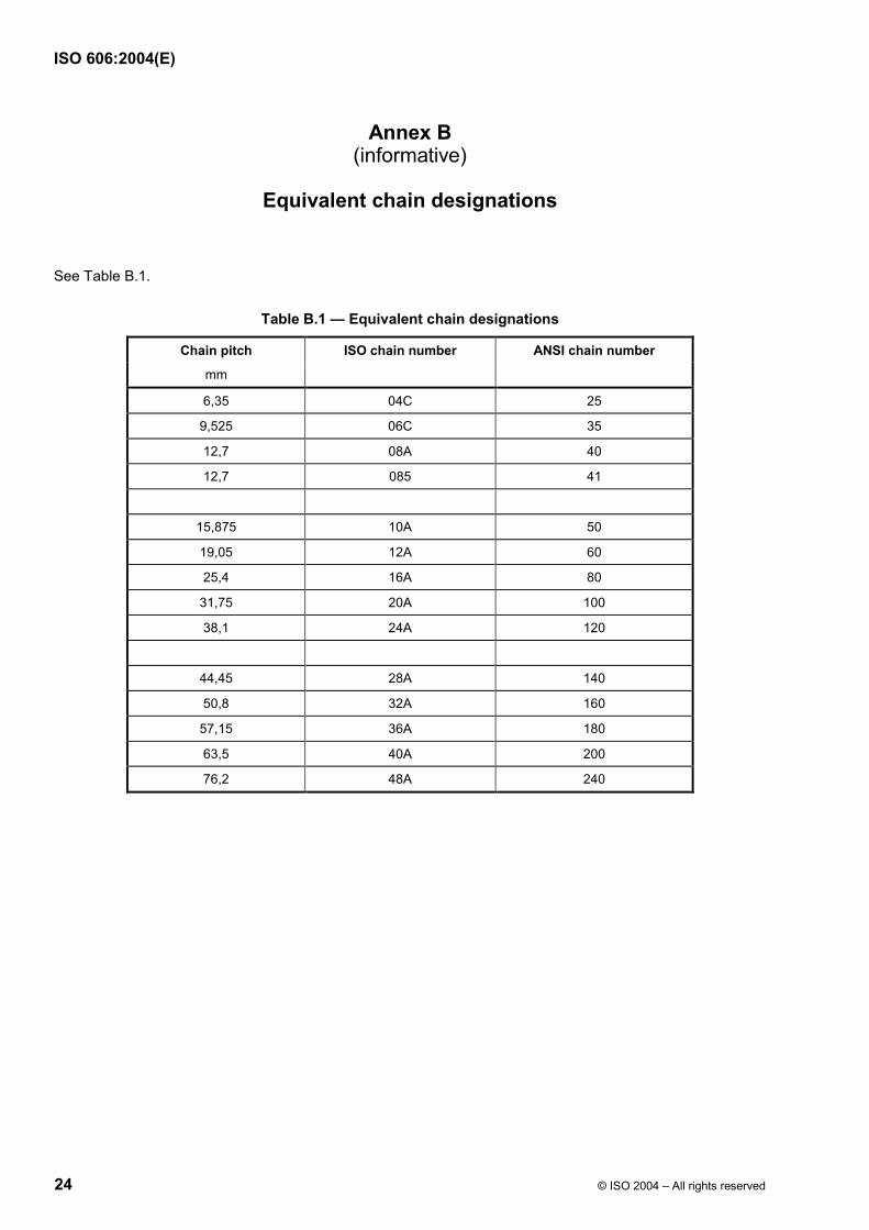
The whole field of application open to this medium of transmission has been covered by the ranges of chains already established. To achieve this, the sizes of 6,35 mm pitch to 76,2 mm pitch inclusive have been duplicated, on the one hand, by the inclusion of chains derived from standards originating and centred around ANSI (denoted by suffix A), and on the other by chains representing the unification of the principal standards originating in Europe (suffix B), the two being complementary for the coverage of the widest possible field of application.
The ANSI chain reference numbers (25, 35, 40, 50, etc.) are used world-wide and, to assist in cross-referencing the ISO and ANSI numbers, details are now included in Annex C of this International Standard.
The ANSI heavy series of chains (suffix H) are also included. The ANSI heavy series of chains differ from the ANSI standard series in that thicker plates are used. As there are no existing ISO numbers for these chains, the ANSI numbering system has been adopted.
Clause 4 covers specification details for K and M attachments, and extended pin attachments for use with short-pitch transmission roller and bush chains conforming with this International Standard.
Clause 5, covering chain sprockets, represents the unification of all the relevant national standards in the world and includes, in particular, complete tolerances relating to tooth form.
The inclusion of the dimensions of the chains specified ensures complete interchangeability of any given size and provides interchangeability of individual links of chains.
This edition also includes short-pitch bush transmission chains previously covered in ISO 1395:1977.
Short-pitch transmission precision roller and bush chains, attachments and associated chain sprockets
1 Scope
This International Standard specifies the characteristics of short-pitch precision roller and bush chains with associated sprockets suitable for the mechanical transmission of power and allied applications. It covers dimensions, tolerances, length measurement, preloading, minimum tensile strengths and minimum dynamic strength.
Although Clause 5 applies to chain sprockets for cycles and motor cycles, this International Standard is not applicable to their chains, which are covered by ISO 9633 and ISO 10190, respectively.
2 Normative references
The following referenced documents are indispensable for the application of this document. For dated references, only the edition cited applies. For undated references, the latest edition of the referenced document (including any amendments) applies.
ISO 286-2:1988, ISO system of limits and fits — Part 2: Tables of standard tolerance grades and limit deviations for holes and shafts
ISO 15654, Fatigue test method for transmission precision roller chains 1)
3 Chains
3.1 Nomenclature of assemblies and components
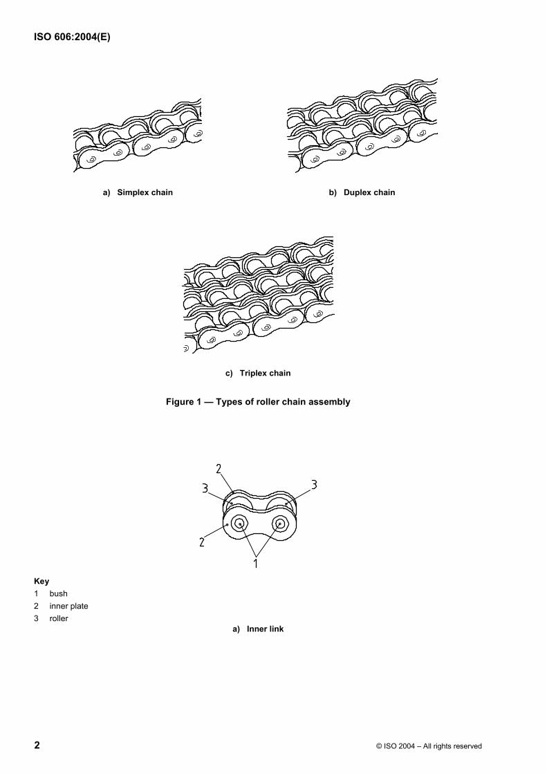
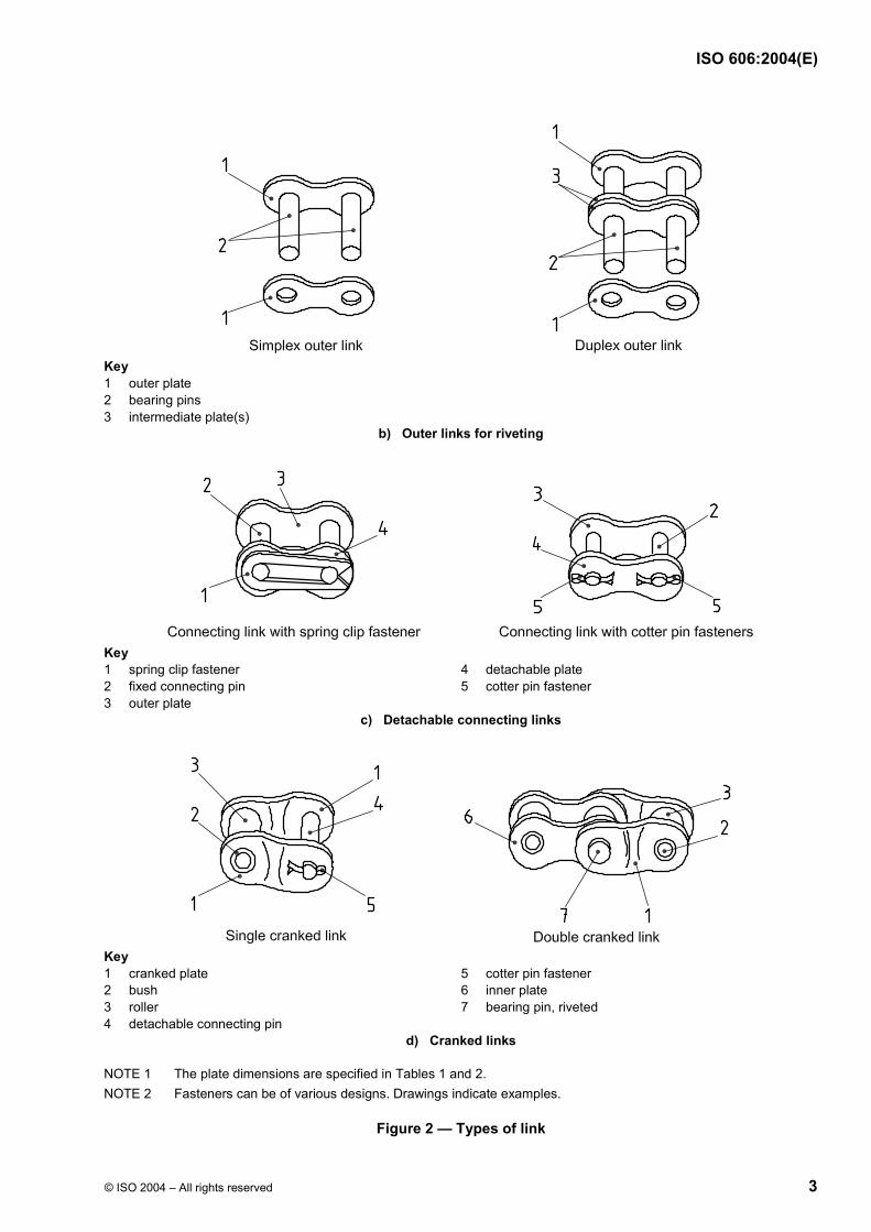
The nomenclature of chain assemblies and their component parts is shown in Figures 1 and 2 (which do not define the actual form of the chain plates).
Chains are designated by the standard ISO chain number given in Tables 1 and 2. The ISO chain numbers in Table 1 are supplemented by a hyphenated suffix 1 for simplex chain, 2 for duplex chain and 3 for triplex chain, for example, 16B-1, 16B-2, 16B-3. Chains 081, 083, 084 and 085 do not follow this procedure since they are normally available in simplex form only.
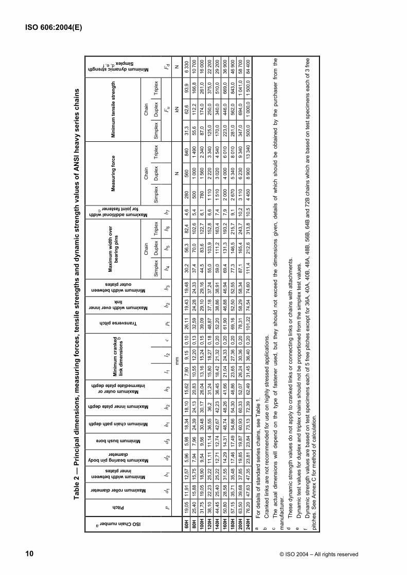
The chains designated in Table 2 are the ANSI heavy series, which are also supplemented by a hyphenated suffix 1 for simplex chain, 2 for duplex chain and 3 for triplex chain, for example, 80H-1, 80H-2, 80H-3.
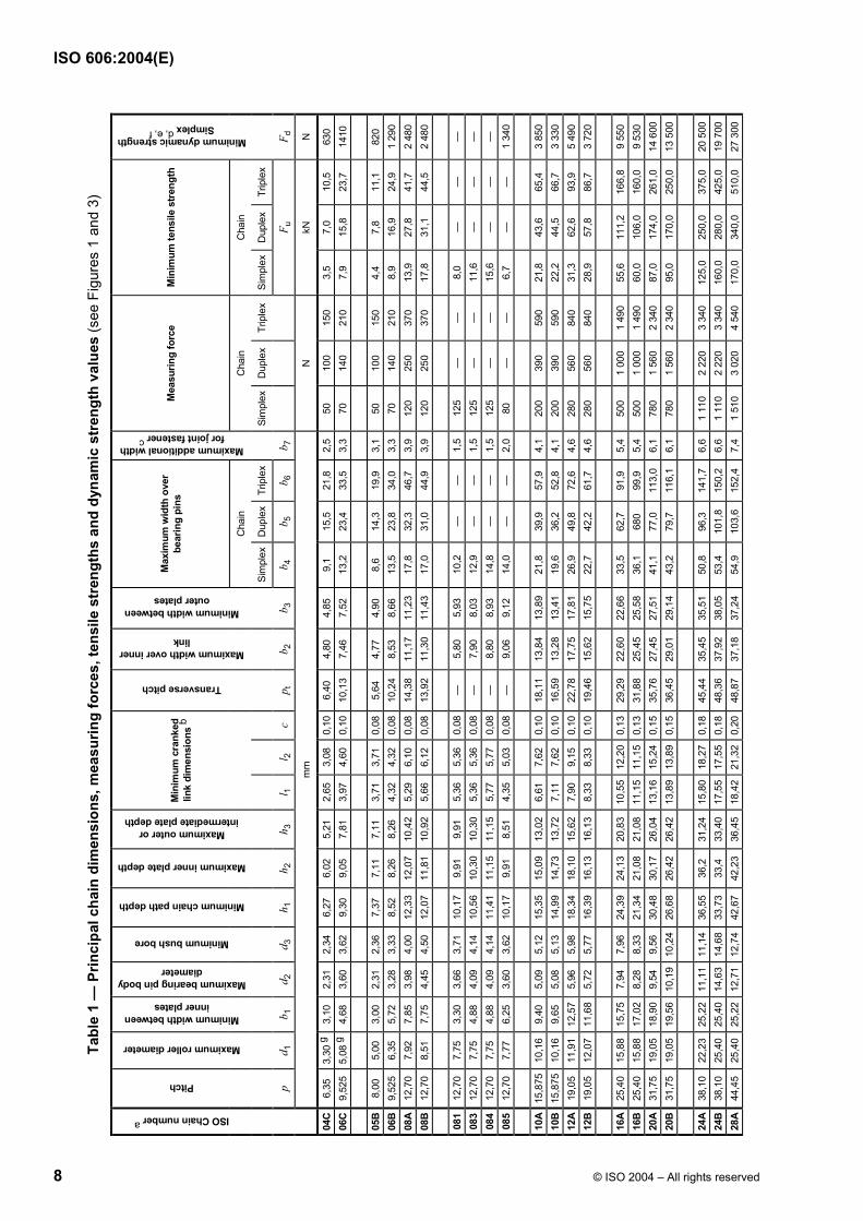
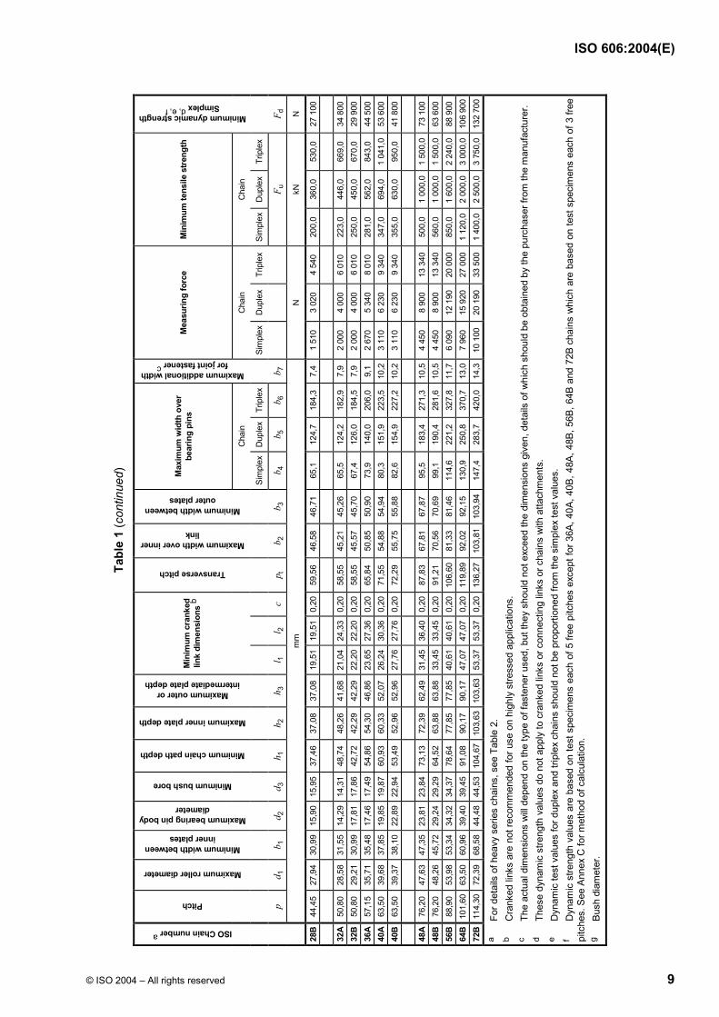
3.3 Dimensions
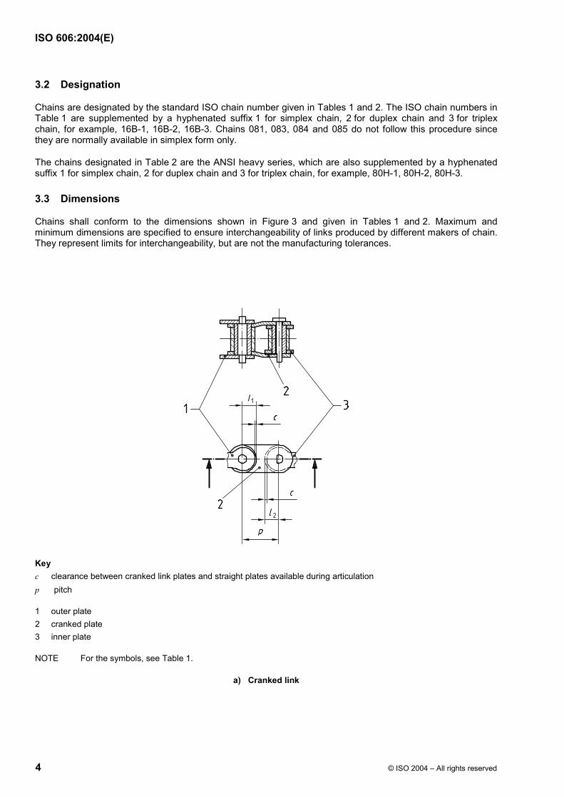
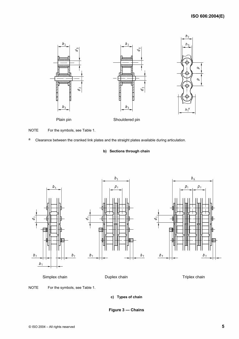
Chains shall conform to the dimensions shown in Figure 3 and given in Tables 1 and 2. Maximum and minimum dimensions are specified to ensure interchangeability of links produced by different makers of chain. They represent limits for interchangeability, but are not the manufacturing tolerances.
Key c clearance between cranked link plates and straight plates available during articulation p pitch
The overall width of a simplex, duplex or triplex chain with a joint fastener is given by
a) for riveted pin end chains if the fastener is on one side only:
(b4 + b7) or (b5 + b7) or (b6 + b7);
b) for riveted pin end chains if the fastener is on two sides:
[b4 + (2b7)] or [b5 + (2b7)] or [b6 + (2b7)];
c) for headed pin end chains if the fastener is on one side only:
[b4 + (1,6b7)] or [b5 + (1,6b7)] or [b6 + (1,6b7)];
d) for headed pin end chains if the fastener is on two sides:
[b4 + (3,2b7)] or [b5 + (3,2b7)] or [b6 + (3,2b7)];
The overall width of chains wider than triplex is given by
b4 + [pt × (number of strands in chain − 1)].
3.4 Performance requirements
3.4.1 General
WARNING — The test requirements are not to be taken as working loads. These loads could be selected, indirectly, using ISO 10823. The test results shall be invalid if the chain has previously been in service or stressed in any way (other than by preloading in accordance with 3.4.3).
The tests given in 3.4.2 to 3.4.5 shall only be performed on unused, undamaged chain to determine whether the subject chain complies with the minimum requirements specified in Tables 1 and 2.
3.4.2 Tensile testing
3.4.2.1 The minimum tensile strength is that value which shall be exceeded when a tensile force is applied to a sample tested to destruction in accordance with 3.4.2.2.
NOTE This minimum tensile strength is not a working load, but is intended primarily as a comparative figure between chains of various constructions.
3.4.2.2 Apply a tensile force slowly to the ends of a chain length containing at least five free pitches by means of fixtures permitting free movement on both sides of the chain centreline, in the normal plane of articulation.
Failure shall be considered to have occurred at the first point where increasing extension is no longer accompanied by increasing force, i.e. the summit of the force/extension diagram. The force at this point shall exceed the minimum tensile strength stated in Tables 1 and 2.
Tests in which failures occur adjacent to the shackles shall be disregarded.
3.4.2.3 The tensile test shall be considered as a destructive test. Even though a chain may not visibly fail when subjected to a force equivalent to the minimum tensile strength, it will have been stressed beyond the yield point and will be unfit for service.
3.4.2.4 These requirements do not apply to cranked links, connecting links or chains with attachments, as their tensile strength could be reduced.
Chains manufactured in conformance with this International Standard shall be preloaded by applying a minimum tensile force equivalent to 30 % of the minimum tensile strength given in Tables 1 and 2.
3.4.4 Length validation
Measurement of chains shall take place after preloading but before lubrication.
The standard length for measurement shall be a minimum of
a) 610 mm for ISO chain numbers 04C to 12B and 081 to 085 inclusive, or
b) 1 220 mm for ISO chain numbers 16A to 72B inclusive.
The chain shall be supported throughout its entire length and the measuring force specified in Tables 1 and 2 shall be applied.
The measured length shall be the nominal length 0,15 %0
+ except for chains with attachments, when it shall be the nominal length 0,30 %
0+ .
The length accuracy of chains which have to work in parallel may be matched within closer tolerances.
3.4.5 Dynamic testing
Chains in conformance with this International Standard shall survive a conformance test, as specified in ISO 15654, using the dynamic strength values given in Tables 1 or 2 for the particular chain. These requirements do not apply to cranked links, connecting links or chains with attachments, as their dynamic strength could be reduced. The methods used for calculating the minimum dynamic strength are given in Annex C. The method for determining the maximum test force for the conformance test is given in Annex D.
3.5 Marking
The chain shall be marked with the manufacturer's name or trademark. The chain number quoted in Tables 1 or 2 should be marked on the chain.
3.6 Cranked links
Cranked links should not be used with the heavy series chains or on chains which are intended for highly stressed applications. Where a cranked link is used a reduction in performance will occur.
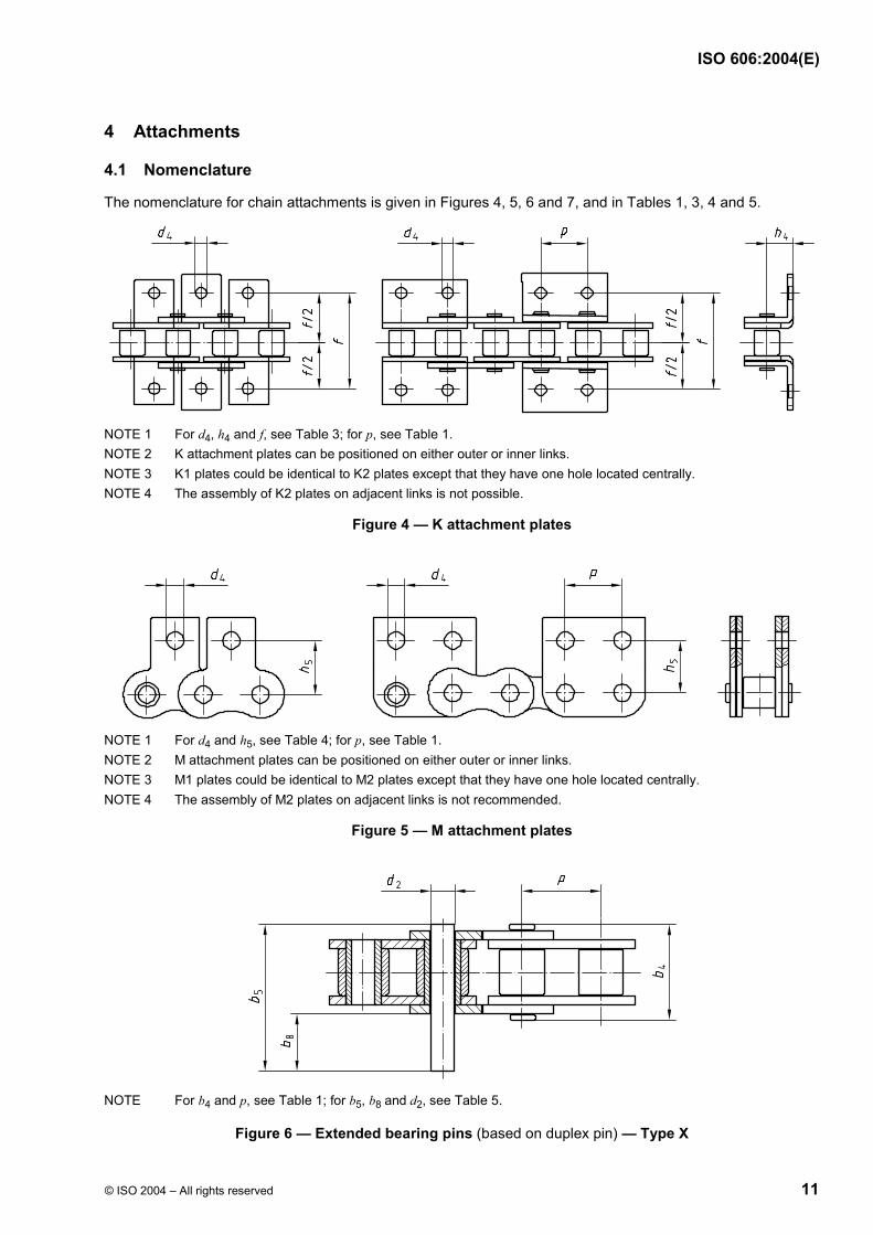
The nomenclature for chain attachments is given in Figures 4, 5, 6 and 7, and in Tables 1, 3, 4 and 5.
NOTE 1 For d4, h4 and f, see Table 3; for p, see Table 1. NOTE 2 K attachment plates can be positioned on either outer or inner links. NOTE 3 K1 plates could be identical to K2 plates except that they have one hole located centrally. NOTE 4 The assembly of K2 plates on adjacent links is not possible.
Figure 4 — K attachment plates
NOTE 1 For d4 and h5, see Table 4; for p, see Table 1. NOTE 2 M attachment plates can be positioned on either outer or inner links. NOTE 3 M1 plates could be identical to M2 plates except that they have one hole located centrally. NOTE 4 The assembly of M2 plates on adjacent links is not recommended.
Figure 5 — M attachment plates
NOTE For b4 and p, see Table 1; for b5, b8 and d2, see Table 5.
Figure 6 — Extended bearing pins (based on duplex pin) — Type X
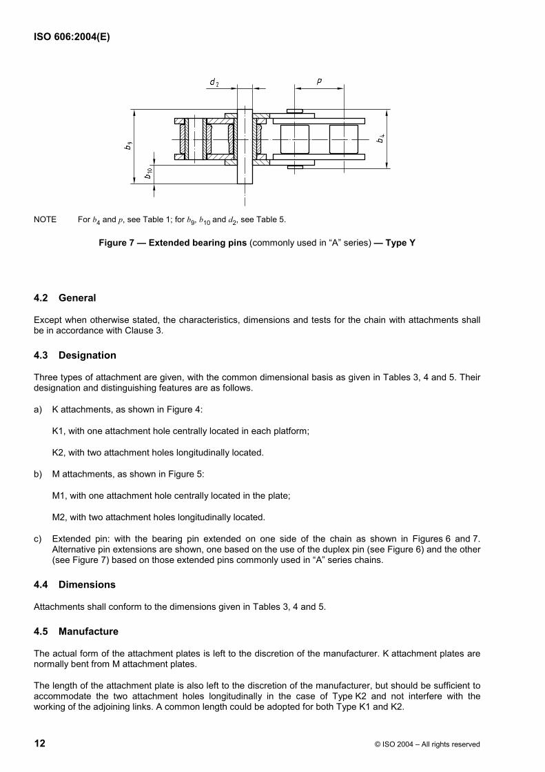
NOTE For b4 and p, see Table 1; for b9, b10 and d2, see Table 5.
Figure 7 — Extended bearing pins (commonly used in “A” series) — Type Y
4.2 General
Except when otherwise stated, the characteristics, dimensions and tests for the chain with attachments shall be in accordance with Clause 3.
4.3 Designation
Three types of attachment are given, with the common dimensional basis as given in Tables 3, 4 and 5. Their designation and distinguishing features are as follows.
a) K attachments, as shown in Figure 4:
K1, with one attachment hole centrally located in each platform;
K2, with two attachment holes longitudinally located.
b) M attachments, as shown in Figure 5:
M1, with one attachment hole centrally located in the plate;
M2, with two attachment holes longitudinally located.
c) Extended pin: with the bearing pin extended on one side of the chain as shown in Figures 6 and 7. Alternative pin extensions are shown, one based on the use of the duplex pin (see Figure 6) and the other (see Figure 7) based on those extended pins commonly used in “A” series chains.
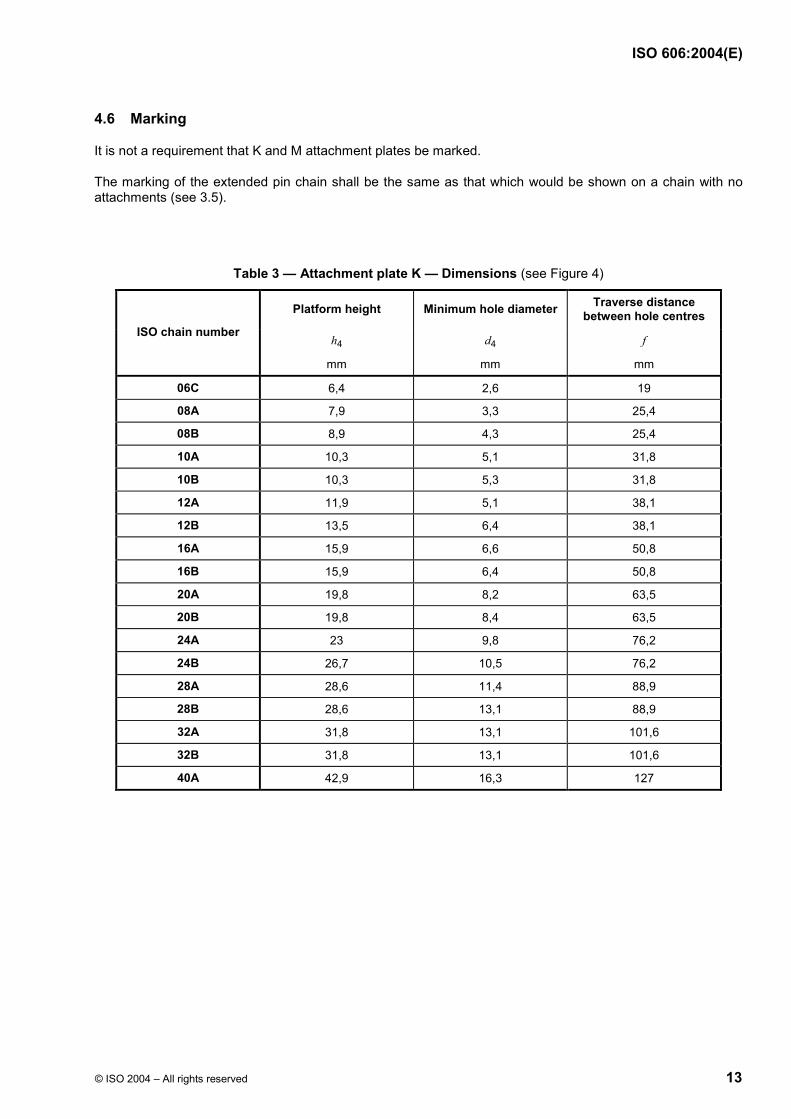
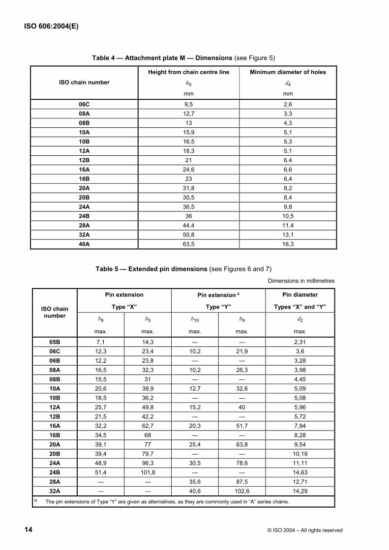
4.4 Dimensions
Attachments shall conform to the dimensions given in Tables 3, 4 and 5.
4.5 Manufacture
The actual form of the attachment plates is left to the discretion of the manufacturer. K attachment plates are normally bent from M attachment plates.
The length of the attachment plate is also left to the discretion of the manufacturer, but should be sufficient to accommodate the two attachment holes longitudinally in the case of Type K2 and not interfere with the working of the adjoining links. A common length could be adopted for both Type K1 and K2.
This clause gives specifications for chain sprockets for use with short-pitch transmission precision roller and bush chains conforming to Clause 3 and specifies general criteria for ensuring correct meshing, operation and transmission of load when used under normal operating conditions.
5.2 Nomenclature
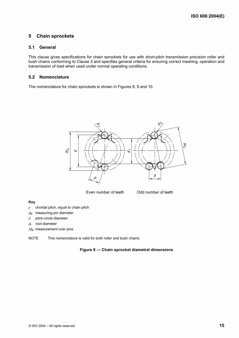
The nomenclature for chain sprockets is shown in Figures 8, 9 and 10.
Key p chordal pitch, equal to chain pitch dR measuring-pin diameter d pitch-circle diameter df root diameter MR measurement over pins
NOTE This nomenclature is valid for both roller and bush chains.
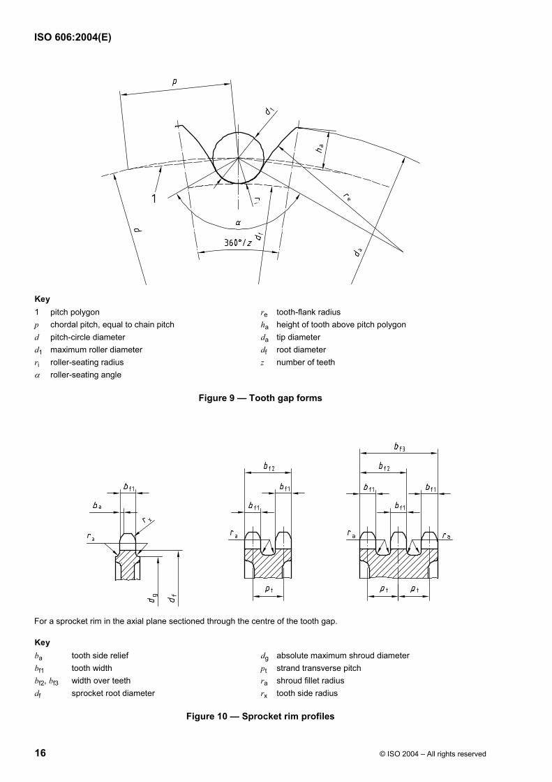
Key 1 pitch polygon re tooth-flank radius p chordal pitch, equal to chain pitch ha height of tooth above pitch polygon d pitch-circle diameter da tip diameter d1 maximum roller diameter df root diameter ri roller-seating radius z number of teeth α roller-seating angle
Figure 9 — Tooth gap forms
For a sprocket rim in the axial plane sectioned through the centre of the tooth gap.
Key ba tooth side relief dg absolute maximum shroud diameter bf1 tooth width pt strand transverse pitch bf2, bf3 width over teeth ra shroud fillet radius df sprocket root diameter rx tooth side radius
For an even number of teeth, the measurement over pins is given by
R R, minM d d= +
For an odd number of teeth, the measurement over pins is given by
R R, min90 cosM d d
z°
= +
The measurement over pins of sprockets with an even number of teeth shall be carried out over pins inserted in opposite tooth gaps.
The measurement over pins of sprockets with an odd number of teeth shall be carried out over pins in the tooth gaps most nearly opposite.
The limits of tolerance for measurement over pins are identical to those for the corresponding root diameters.
5.4 Sprocket tooth gap forms
5.4.1 Nomenclature
See Figure 9.
5.4.2 Dimensions
5.4.2.1 General
The limits of the tooth gap form are determined by the minimum and maximum tooth gap forms. The actual tooth gap form, which is provided by cutting or an equivalent method, shall have tooth flanks of a form lying between the minimum and maximum flank radii and blending smoothly with the roller seating curve subtending the respective angles.
5.4.2.2 Minimum form
The corresponding values for re, ri and α are given by
re,max = 0,12d1 (z + 2)
ri,min = 0,505d1
αmax = 140°− 90z
°
5.4.2.3 Maximum form
The corresponding values for re, ri and α are given by
The maximum and minimum values of the tip diameter da are given by
da,max = d + 1,25p − d1
da,min = d + p 11,61 dz
− −
NOTE da,min and da,max can be applied arbitrarily both to the minimum and maximum gap forms, subject to the limitations imposed on the maximum diameter by the cutter.
To facilitate the construction of the tooth gap form to a large scale, the tooth height above the pitch polygon can be obtained from the following formulae:
ha,max = 0,625p − 0,5d1 + 0,8 pz
ha,min = 0,5 (p − d1)
NOTE ha,max is related to da,max and ha,min to da,min.
5.6 Sprocket rim profiles
5.6.1 Nomenclature
See Figure 10.
5.6.2 Dimensions
5.6.2.1 Tooth width
Tooth width dimensions are given by the following.
a) For p u 12,7 mm:
bf1 = 0,93b1 : h14 2) for simplex chain sprockets;
bf1 = 0,91b1 : h14 for duplex and triplex chain sprockets;
bf1 = 0,88b1: h14 for quadruplex chain wheels and above.
b) For p > 12,7 mm:
bf1 = 0,95b1 : h14 for simplex chain sprockets;
bf1 = 0,93b1 : h14 for duplex and triplex chain sprockets.
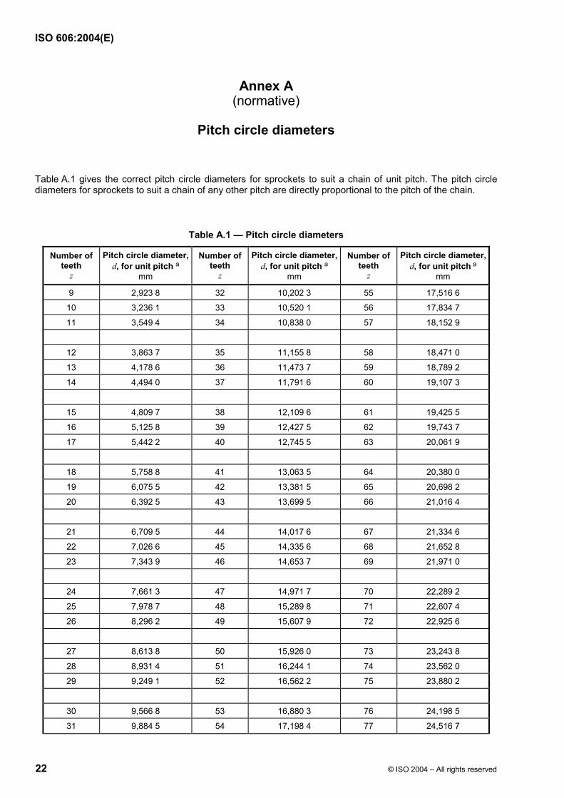
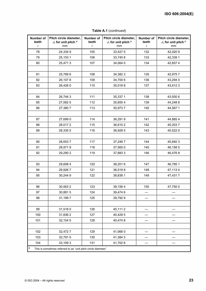
Table A.1 gives the correct pitch circle diameters for sprockets to suit a chain of unit pitch. The pitch circle diameters for sprockets to suit a chain of any other pitch are directly proportional to the pitch of the chain.
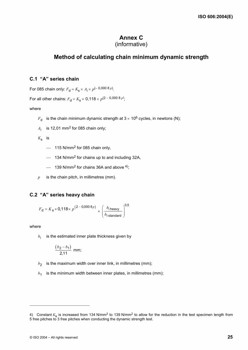
Method of calculating chain minimum dynamic strength
C.1 “A” series chain
For 085 chain only: Fd = Ks × Ai × p(− 0,000 8 p).
For all other chains: Fd = Ks × 0,118 × p(2 − 0,000 8 p);
where
Fd is the chain minimum dynamic strength at 3 × 10⁶ cycles, in newtons (N);
Ai is 12,01 mm2 for 085 chain only;
Ks is
115 N/mm2 for 085 chain only,
134 N/mm2 for chains up to and including 32A,
139 N/mm2 for chains 36A and above 4);
p is the chain pitch, in millimetres (mm).
C.2 “A” series heavy chain
( )2 0,000 8d s 0,118 pF K p −= × × ×
0,5i heavy
i standard
bb
where
bi is the estimated inner plate thickness given by
( )2 12,11
b b− mm;
b2 is the maximum width over inner link, in millimetres (mm);
b1 is the minimum width between inner plates, in millimetres (mm);
4) Constant Ks is increased from 134 N/mm2 to 139 N/mm2 to allow for the reduction in the test specimen length from 5 free pitches to 3 free pitches when conducting the dynamic strength test.
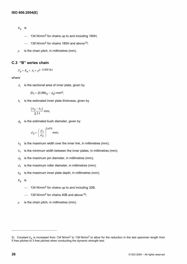
bi is the estimated inner plate thickness, given by
( )2 1 mm;2,11
b b−
db is the estimated bush diameter, given by
0,4751
22
mm;ddd
×
b2 is the maximum width over the inner link, in millimetres (mm);
b1 is the minimum width between the inner plates, in millimetres (mm);
d2 is the maximum pin diameter, in millimetres (mm);
d1 is the maximum roller diameter, in millimetres (mm);
h2 is the maximum inner plate depth, in millimetres (mm);
Ks is
134 N/mm2 for chains up to and including 32B,
139 N/mm2 for chains 40B and above 5);
p is the chain pitch, in millimetres (mm).
5) Constant Ks is increased from 134 N/mm2 to 139 N/mm2 to allow for the reduction in the test specimen length from 5 free pitches to 3 free pitches when conducting the dynamic strength test.
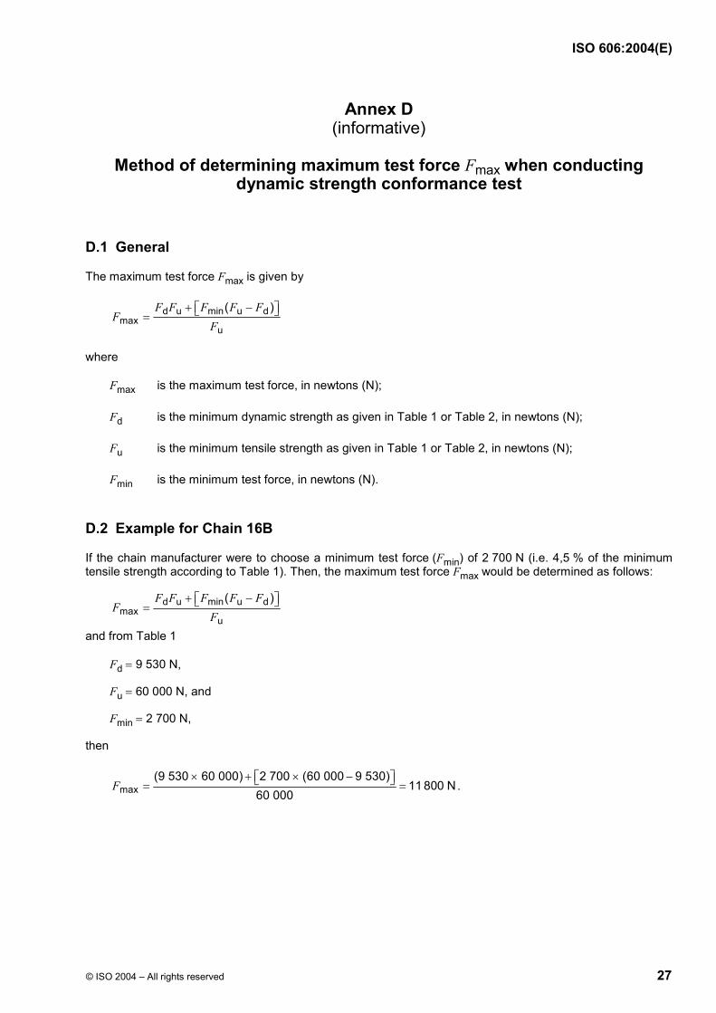
Method of determining maximum test force Fmax when conducting
dynamic strength conformance test
D.1 General
The maximum test force Fmax is given by
d u min u dmax
u
( )F F F F FF
F+ − =
where
Fmax is the maximum test force, in newtons (N);
Fd is the minimum dynamic strength as given in Table 1 or Table 2, in newtons (N);
Fu is the minimum tensile strength as given in Table 1 or Table 2, in newtons (N);
Fmin is the minimum test force, in newtons (N).
D.2 Example for Chain 16B
If the chain manufacturer were to choose a minimum test force (Fmin) of 2 700 N (i.e. 4,5 % of the minimum tensile strength according to Table 1). Then, the maximum test force Fmax would be determined as follows: