48
Siemens MC General Product Description V2.3.doc Page 1 of 48 Copyright © Siemens AG 1999, 2000 ICM CD IS (Information Security) GENERAL PRODUCT DESCRIPTION SIEMENS MONITOR CENTER
| Date post: | 29-Mar-2018 |
| Category: |
Documents |
| Upload: | truongnguyet |
| View: | 222 times |
| Download: | 2 times |

Siemens MC General Product Description V2.3.doc Page 1 of 48Copyright © Siemens AG 1999, 2000ICM CD IS (Information Security)
GENERAL PRODUCT DESCRIPTION
SIEMENS MONITOR CENTER

Siemens MC General Product Description V2.3.doc Page 2 of 48Copyright © Siemens AG 1999, 2000ICM CD IS (Information Security)
Table of Contents
1. SCOPE.............................................................................................................5
1.1. IDENTIFICATION ..................................................................................................... 51.2. PURPOSE ................................................................................................................ 5
2. DEFINITIONS ..................................................................................................6
2.1. MONITOR CENTER ................................................................................................. 62.2. MONITORING........................................................................................................... 62.3. GENERAL DEFINITIONS......................................................................................... 8
3. DESIGN OVERVIEW .....................................................................................11
3.1. HIGH LEVEL DESIGN............................................................................................ 113.2. GEOGRAPHICAL DISTRIBUTION ........................................................................ 12
4. MONITOR CENTER FRONT-END: GENERIC...............................................13
4.1. FRONT-END: PASSIVE MONITORING ................................................................ 144.1.1. Passive Monitoring Front-End components .................................................... 15
4.1.1.1. Acquisition Units, Recorders (AQ) ............................................................... 15DVX – Switching Multiplexer ......................................................................................... 164.1.1.3. Protocol Analyser (PA) ................................................................................. 174.1.1.4. Recording Controller (CTRL)........................................................................ 184.1.1.5. Supervisor Station (SVR) ............................................................................. 18
4.2. FRONT-END: ACTIVE MONITORING................................................................... 194.2.1. General............................................................................................................. 19
4.2.1.1. Dual Route Interfaces (DRI) ......................................................................... 214.2.1.2. Single Route Interface (SRI) ........................................................................ 22
4.2.2. Statistical Monitoring ........................................................................................ 224.2.3. Active Monitoring Front-End components ....................................................... 23
4.2.3.1. Acquisition Unit ............................................................................................. 234.2.3.2. Call Controller (CC)....................................................................................... 244.2.3.3. S-Record-Controller (LI-Rec.-Contr.) ........................................................... 24
5. MONITOR CENTER BACK-END ...................................................................25
5.1. BACK-END FUNCTIONALITY ............................................................................... 255.1.1. Dossier based administration: ......................................................................... 255.1.2. Dossier based archiving of intercepts:............................................................. 255.1.3. Dossier based access to the intercepts:.......................................................... 255.1.4. Hot / On-line Monitoring: .................................................................................. 255.1.5. Processing of intercepts:.................................................................................. 26
5.2. BACK-END COMPONENTS .................................................................................. 265.2.1. Principle Overview............................................................................................ 26Management Station / Supervisor Station for EWSD...................................................... 27
5.2.2.1. Supervisor Station for EWSD....................................................................... 275.2.2.2. Dossier Administration / MC Manager ......................................................... 27
5.2.3. MC Controller (MCC)........................................................................................ 295.2.4. MC Database ................................................................................................... 305.2.5. Storage System / Dossier Storage .................................................................. 31

Siemens MC General Product Description V2.3.doc Page 3 of 48Copyright © Siemens AG 1999, 2000ICM CD IS (Information Security)
5.2.5.1. Export of data from Dossier Storage............................................................ 325.2.5.2. Management of storage volumes ................................................................ 325.2.5.3. Restoration of data ....................................................................................... 33
5.2.6. Operator Station / Unified User Station ( UUS ) .............................................. 345.2.6.1. Playback ....................................................................................................... 355.2.6.2. Hot / On-Line Monitoring .............................................................................. 355.2.6.3. Fax Display ................................................................................................... 365.2.6.4. Transcription ................................................................................................. 36
5.2.7. Fax and data Demodulation............................................................................. 375.2.7.1. Siemens Fax Demodulator........................................................................... 37Fax/Data Demodulation System................................................................................... 385.2.7.3. Manual or automatic data analysis............................................................... 39
6. ALARMS........................................................................................................40
7. EVENT LOGGING .........................................................................................41
8. MC SECURITY...............................................................................................42
8.1. DOSSIER STORAGE FILE SECURITY................................................................. 428.2. DATABASE SECURITY ......................................................................................... 428.3. PHYSICAL SECURITY........................................................................................... 42
9. SCALABILITY................................................................................................43
10. RELIABILITY...............................................................................................44
10.1. SYSTEM TIME..................................................................................................... 4410.2. POWER SUPPLY................................................................................................ 4410.3. THERMAL CONTROL......................................................................................... 4410.4. MIRRORING OF DATA....................................................................................... 4410.5. MAINTAINABILITY .............................................................................................. 44
11. UPGRADIBILITY .........................................................................................45
12. TARGET ADMINISTRATION.......................................................................46
12.1. PASSIVE MONOITORING.................................................................................. 4612.2. ACTIVE MONITORING ....................................................................................... 46
13. MULTI MONITORING SETUP.....................................................................47
13.1. PASSIVE MONITORING..................................................................................... 4713.2. ACTIVE MONITORING ....................................................................................... 47
14. DOCUMENT REVISION HISTORY .............................................................48

Siemens MC General Product Description V2.3.doc Page 4 of 48Copyright © Siemens AG 1999, 2000ICM CD IS (Information Security)
Table of Figures
Figure 2-1: Active Monitoring: Connection MC into the Communication Network................ 6Figure 2-2: Passive Monitoring: Connection MC into the Communication Network............. 7Figure 3-1: High level design ............................................................................................... 11Figure 3-2: Geographical Distribution .................................................................................. 12Figure 4-1: Example of Front-End for passive monitoring .................................................. 14Figure 4-2: Example of Front-End for active monitoring ..................................................... 20Figure 4-3: Dual Route Interface (DRI)................................................................................ 21Figure 4-4: Single Route Interface (SRI) ............................................................................. 22Figure 5-1: Monitor Center Back-End.................................................................................. 26

Siemens MC General Product Description V2.3.doc Page 5 of 48Copyright © Siemens AG 1999, 2000ICM CD IS (Information Security)
1. SCOPE
1.1. IDENTIFICATION
This document contains the general product description of the Siemens Monitor Center.This Monitor Center represents the second generation making use of variable modulesaccording to the different public communication networks (Front-Ends) and a commonmodule for all solutions (Back-End).
1.2. PURPOSE
The main purpose of this document is to describe the basic functionality of the SiemensMonitor Center.
NOTE:
This document is subject to changes without prior notice.
It is intended for informational purposes only

Siemens MC General Product Description V2.3.doc Page 6 of 48Copyright © Siemens AG 1999, 2000ICM CD IS (Information Security)
2. DEFINITIONS
2.1. MONITOR CENTER
A Monitor Center (MC) refers to a physical installation used to intercept and recordinformation transferred over telecommunication networks in an endeavor to supportgovernment agencies (Law Enforcement Agencies LEAs) in crime prevention and/orintelligence gathering activities.
2.2. MONITORING
Monitoring refers to an intercept of speech and/or data exchanged between two or agroup of subscribers by a third party within a communication network.
Basically there are two possibilities in monitoring:
♦ Active Monitoring refers to the fact that the target (phone) numbers to be monitoredare marked from within the network. The Monitoring functionality is a built in functionof the “Switch”. For monitoring purposes, only targeted phone calls are routed to theMC. This can be compared with a three party conference call, in which the MC is asilent member of the conference call. Active Monitoring plays an active role in thecommunication network, in the sense that the Monitor Center is viewed as asubscriber to the network with a certain service level. Lawful Interception is anexample for Active Monitoring.
Figure 2-1: Active Monitoring: Connection MC into the Communication Network
GSM or PSTN
Switch1)
X.25Network
IRIand
Marking
InterceptRelated
Information(IRI)Terminal(s) for
andhandling of
Intercept RelatedInformation (IRI)
Administration
1) Monitoring Functionality in the switch must be provided by the Operator/Switch Manufacturer
2) depending on the Operator/Switch-Manufacturer
2)
Monitor Center
MC FRONT-ENDMC FRONT-ENDSwitch TypeSwitch Type
MC BACK-ENDMC BACK-END
LAN
Speech/DatatransmissionContent of
Communication(CC)

Siemens MC General Product Description V2.3.doc Page 7 of 48Copyright © Siemens AG 1999, 2000ICM CD IS (Information Security)
♦ Passive Monitoring refers to the fact that no target number information is kept insidethe network. Connection is made i.e. to trunk lines via high impedance couplingdevices between switches. The database of target numbers is administered inside theMC. The Monitor Center, therefore, plays a passive role in the communicationsnetwork. A large number of trunks are thus monitored with typically only a few callsbeing selected for recording at any moment.
Within the Siemens Monitor Center there is distinguished between the two Monitor Centerapplications merely by a difference in the Front-End.
Figure 2-2: Passive Monitoring: Connection MC into the Communication Network
Monitor Center
MC FRONT-ENDMC FRONT-ENDTrunk
MC BACK-ENDMC BACK-END
GSM or PSTN
Switch
LAN
= Coupling Devices
Complete Trunk Groups
Switch

Siemens MC General Product Description V2.3.doc Page 8 of 48Copyright © Siemens AG 1999, 2000ICM CD IS (Information Security)
2.3. GENERAL DEFINITIONS
BRI
Basic Rate Interface
Call
Any connection capable of transferring information between two or more users of atelecommunications system. In this context a user may be a person or a machine.
Call Content (CC)
The information exchanged between two or more users of a telecommunications service,excluding intercept related information.
Call Related Data (CRD) / S-Record / LI-Record / Intercept Related Information (IRI)
A collection of information or data associated with telecommunication services involvingthe target identity, specifically call associated information or data (e.g. unsuccessful callattempts), service associated information or data (e.g. service profile management bysubscriber) and location information.
CLIP (Calling Line Identification Presentation)
CLIP is an ISDN authentication feature. The number of the calling party is present for thecalled party.
COLP (Connected Line Identification Presentation)
COLP is an ISDN authentication feature. The number of the called party is present for thecalling party. So it would be possible to notice call forwarding to another target.
CUG (Closed User Group)
CUG is an ISDN authentication feature. A group of users restricted there usage of thenetwork to communications inside the group.
Dossier
The term Dossier refers to all interceptions / intercepts relating to a specific monitoredtarget or targets. A dossier is a collection of intercepts for a specific set of monitoredtarget(s). It typically serves as evidence in a court case and represents all the Calls madeby the target(s) involved in the court case that was monitored.

Siemens MC General Product Description V2.3.doc Page 9 of 48Copyright © Siemens AG 1999, 2000ICM CD IS (Information Security)
DRI (Dual Route Interface) / Standard Interception
The Call Content and the Call Related Data, of an interception, are transmitted to theMonitor Center via two physically separated interfaces.
Intercept
Call Content or Call Related Data of a monitored target.
Interception
The action, performed by an access provider / network operator / service provider, ofmaking available certain information (Call Content and Call Related Data) of a markedtarget and providing that to the Monitor Center.
Intercept event
An intercept event is generated based on a recording activity from the recording side (MCFront-End) and is sent to the common MC Back-End. It contains all relevant information orreferences to information about the intercepted communication.
IRI
Intercept Related Information. A collection of information or data associated withtelecommunication services involving the target identity, specifically call associatedinformation or data (e.g. unsuccessful call attempts), service associated information ordata (e.g. service profile management by subscriber) and location information.
Law Enforcement Agency (LEA)
An organization authorized by a lawful authorization based on a national law to requestinterception measures and to receive the results of telecommunications interceptions.
LI
Lawful Interception
PRI
Primary Rate Interface
Split Stereo
The two different directions of a telephone communication are transmitted to the MonitorCenter via two mono calls.

Siemens MC General Product Description V2.3.doc Page 10 of 48Copyright © Siemens AG 1999, 2000ICM CD IS (Information Security)
SRI (Single Route Interface) / Switch Feature, Restricted Interception
The call content and the call related data, of an interception, are transmitted to the MonitorCenter via one physical interface.
SUB
ISDN Subaddressing.
Target
A person or persons, specified in a lawful authorization, whose telecommunications are tobe intercepted.
Target Administration
Marking of targets (subscribers, triggers), e.g. enter new interception decision.
Siemens MC General Product Description V2.3.doc Page 11 of 48Copyright © Siemens AG 1999, 2000ICM CD IS (Information Security)
3. DESIGN OVERVIEW
A primary goal of the design of the Monitor Center system was to find as much commonalitybetween Active Monitoring and Passive Monitoring as possible, as well as to integratedifferent switch types or networks into one solution. This document describes the commonparts of the products.
3.1. HIGH LEVEL DESIGN
The purpose of a Monitor Center system is to intercept communication, organizeintercepts and facilitate access to, and processing of intercepts.
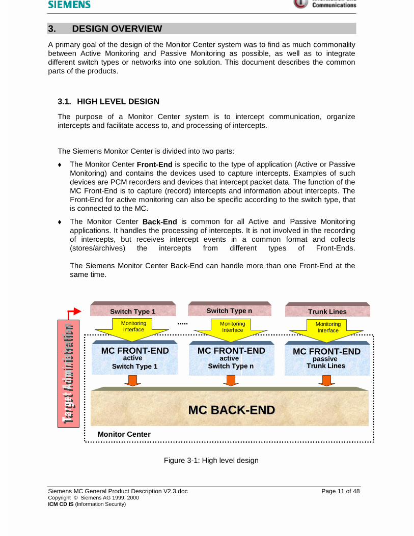
The Siemens Monitor Center is divided into two parts:
♦ The Monitor Center Front-End is specific to the type of application (Active or PassiveMonitoring) and contains the devices used to capture intercepts. Examples of suchdevices are PCM recorders and devices that intercept packet data. The function of theMC Front-End is to capture (record) intercepts and information about intercepts. TheFront-End for active monitoring can also be specific according to the switch type, thatis connected to the MC.
♦ The Monitor Center Back-End is common for all Active and Passive Monitoringapplications. It handles the processing of intercepts. It is not involved in the recordingof intercepts, but receives intercept events in a common format and collects(stores/archives) the intercepts from different types of Front-Ends.
The Siemens Monitor Center Back-End can handle more than one Front-End at thesame time.
Figure 3-1: High level design
Switch Type 1
MC BACK-ENDMC BACK-END
Trunk Lines
MC FRONT-END
Switch Type 1Switch Type 1
MC FRONT-END
Switch Type nSwitch Type n
MC FRONT-END
Trunk LinesTrunk Lines
Monitor Center
MonitoringInterface
Switch Type n
..........
active passiveactive
MonitoringInterface
MonitoringInterface

Siemens MC General Product Description V2.3.doc Page 12 of 48Copyright © Siemens AG 1999, 2000ICM CD IS (Information Security)
3.2. GEOGRAPHICAL DISTRIBUTION
The Monitor Center may be distributed over a number of sites (physical locations). This istrue for the geographical location of any of the organizational sub structures.
The following figure shows the possible distribution of a generic Monitor Center in order toillustrate the different locations of subsystems.
Figure 3-2: Geographical Distribution
In most cases the Monitor Center will be situated at one physical site and serves a singleLEA but different local groups within the LEA. However the Monitor Center can also bedistributed over a number of sites. These sites could be for housing of different LEAs orLEA groups or access points to the transmission media (a mechanism which passesinformation between a network operator or service provider and a Monitor Center).
The Siemens Monitor Center uses TCP/IP as transmission protocol, which enables LANas well as WAN applications. LAN support exists for 10 Mbps and 100 Mbps Ethernet.
Communication Network
MC1 / LEA1
Front-End
Back-End
RemoteAccess
LEA1-group
MC2 / LEA2
Front-End
Back-End
RemoteAccess
LEA2-group
LAN/WAN
LAN/WAN

Siemens MC General Product Description V2.3.doc Page 13 of 48Copyright © Siemens AG 1999, 2000ICM CD IS (Information Security)
4. MONITOR CENTER FRONT-END: GENERIC
The function of the Front-End is to capture intercepts and relay intercept events to the MCBack-End. In telecommunication monitoring the Front-End could be a digital or analogueinterface. In packet data networks the Front-End could include a device to capture datapackets, email messages, etc.
These intercept events are relayed to the MC Back-End via an Event Interface. The Back-End detects the events and manages it accordingly.
Fax and Data detection is performed on the Front-End and a 64 kbit/s recording is startedautomatically. Standard fax detection is performed based on the 2100 Hz answer (pilot) tonewithin a fax transmission. The tone may occur anywhere within a recording. Faxes may alsobe identified by detecting the ISDN type of service. If the type of service is available, and itidentifies the call as a fax transmission, the intercept is marked as such and this implies a64 kbit/s recording. Detection and Recording of data is performed in the same manner.
For passive monitoring applications that include the DVX switching multiplexer, alsoenhanced fax/data detection algorithms based on the modulation itself are available.

Siemens MC General Product Description V2.3.doc Page 14 of 48Copyright © Siemens AG 1999, 2000ICM CD IS (Information Security)
4.1. FRONT-END: PASSIVE MONITORING
In Passive Monitoring applications (e.g. for international trunk lines) telecommunicationtransmission lines are monitored passively. The connection to these lines is normally donevia high impedance coupling devices.
Signaling supported by different Passive Siemens Monitor Center Front-Ends:
♦ SS7 ISUP/TUP
♦ R1
♦ R2
♦ No. 5
♦ Analogue lines
♦ E1 without signalling
The validity of the signal frame (HDB3) can be checked on the recorder and errors arethen reported via alarm functions.
♦ ISDN PRI and ISDN BRI (EDSS1)
The following passive protocols are considered for implementation:
♦ T1 without signalling
see E1 without signalling
♦ ISDN (USA)
♦ POTS
Acquisition Unit
Acquisition Unit
Coupling Devices
signallingtimeslots
DVX
CCS7 ISUP
LAN
to the Back-end
Front-End
AQ
CTRL
SVR
PA
Figure 4-1: Example of Front-End for passive monitoring

Siemens MC General Product Description V2.3.doc Page 15 of 48Copyright © Siemens AG 1999, 2000ICM CD IS (Information Security)
4.1.1. Passive Monitoring Front-End components
4.1.1.1. Acquisition Units, Recorders (AQ)
The Acquisition Units (AQ), shortly referred to as the “Recorders” will store thetargets communication contents (like speech or data traffic) as well as additionaldata that is necessary and valuable to identify and analyse the recorded information.The Recorder is equipped with digital PCM E1 interfaces that connect to the PCMoutputs of the DVX Multiplexer. The recordings are stored on harddisk for immediateand direct on-line access and are handed over (copied) to the MC Backend forcentralised storage and archiving.
One Acquisition Unit can handle up to 60 channels simultaneously. According to therequirements, one Front-End can consist of several Acquisition Units.
Acquisition Unit

Siemens MC General Product Description V2.3.doc Page 16 of 48Copyright © Siemens AG 1999, 2000ICM CD IS (Information Security)
4.1.1.2. DVX – Switching Multiplexer
The Monitor Center connects to digital streams via the DVX switch. CAS signallingon these trunks is directly processed on the DVX in order to determine importantinformation such as the originating and destination addresses of the communicatingparties. It also analyses the signal to determine fax/data communication. Thisinformation is essential for recording decisions.
Switching of intercepts through to recording equipment is based on rules andattributes, which are configurable. This is a function of the Recording Controllerwhich also holds a trigger table for the targeted communication activities.
In the case of SS7 signalling, the timeslots bearing signalling information (signallinglinks/link sets) are switched to an external protocol analyser which performs thesignalling analysis.

Siemens MC General Product Description V2.3.doc Page 17 of 48Copyright © Siemens AG 1999, 2000ICM CD IS (Information Security)
4.1.1.3. Protocol Analyser (PA)
The Protocol Analyser (PA) for SS7 signalling (ISUP and/or TUP) decodes thesignalling information that is switched through by the DVX. The PA allows to beconfigured according to the configuration that is used within the signalling network,i.e., the definitions of load sharing groups/signalling link sets, the signalling pointcodes of the exchanges that have to be included into the monitoring as well asnecessary mapping functions for the PCM numbers and timeslots (CIC (CircuitIdentification Code) mapping) to reference logical and physical numbering of boththe communication links and the DVX inputs. The PA has a graphical userinterfaces to allow configuration, testing and supervision of the signalling analysis.Once configured, the PA runs on ist own as a “black box”. The decoded signalinformation is sent via LAN to the Recording Controller that controls switching of themultiplexer and recording on the Acquisition Units accordingly.
Siemens MC General Product Description V2.3.doc Page 18 of 48Copyright © Siemens AG 1999, 2000ICM CD IS (Information Security)
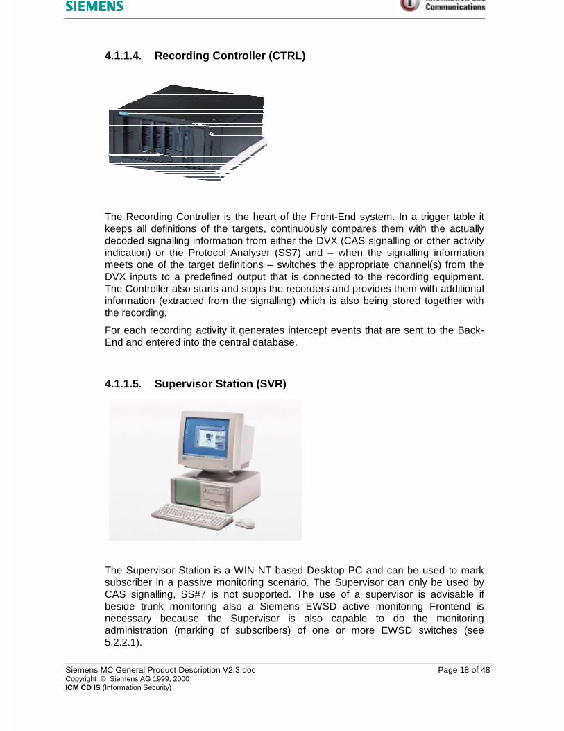
4.1.1.4. Recording Controller (CTRL)
The Recording Controller is the heart of the Front-End system. In a trigger table itkeeps all definitions of the targets, continuously compares them with the actuallydecoded signalling information from either the DVX (CAS signalling or other activityindication) or the Protocol Analyser (SS7) and – when the signalling informationmeets one of the target definitions – switches the appropriate channel(s) from theDVX inputs to a predefined output that is connected to the recording equipment.The Controller also starts and stops the recorders and provides them with additionalinformation (extracted from the signalling) which is also being stored together withthe recording.
For each recording activity it generates intercept events that are sent to the Back-End and entered into the central database.
4.1.1.5. Supervisor Station (SVR)
The Supervisor Station is a WIN NT based Desktop PC and can be used to marksubscriber in a passive monitoring scenario. The Supervisor can only be used byCAS signalling, SS#7 is not supported. The use of a supervisor is advisable ifbeside trunk monitoring also a Siemens EWSD active monitoring Frontend isnecessary because the Supervisor is also capable to do the monitoringadministration (marking of subscribers) of one or more EWSD switches (see5.2.2.1).

Siemens MC General Product Description V2.3.doc Page 19 of 48Copyright © Siemens AG 1999, 2000ICM CD IS (Information Security)
4.2. FRONT-END: ACTIVE MONITORING
4.2.1. General
In Active Monitoring applications, also referred to as subscriber monitoring, activeconnections (call setups) are established to the Monitor Center and Intercept RelatedInformation (IRI) may be routed via a single route interface (SRI) or a dual routeinterface (DRI). Additional descriptions of the two interfaces are as follows:
♦ Single Route interface (SRI) entails that call related information is passed through thesame link as the call content.
♦ Dual Route Interface (DRI) entails that call related information is passed through adifferent link than the call content.
Both of the above interfaces are supported by the Monitor Center.
The Front-End is designed to provide a multi-vendor-capability this allows an easyadaptation of other interfaces from different Switch Manufacturers.
Signalling supported by different Active Siemens Monitor Center Front-Ends:
ISDN / EDSS1 (PRI, BRI)
R2D
In the case of EDSS1 CUG, COLP, CLIP and SUB are supported in order toauthenticate the Monitor Center.
The following active protocols are considered for implementation:
T1
ISDN (USA)
POTS

Siemens MC General Product Description V2.3.doc Page 20 of 48Copyright © Siemens AG 1999, 2000ICM CD IS (Information Security)
Figure 4-2: Example of Front-End for active monitoring
MCMCFRONT-ENDFRONT-END
CC- InterfaceEDSS1 S2M
Acquisition Unit
Call Controller IRI Controller(S-Record Controller)
Terminal for
Switch
Intercept RelatedInformation (IRI)
andhandling of
Intercept RelatedInformation (IRI)
X.25
AdministrationLAN
X.25
MC-Back-End
Intercept EventInterface
Intercept ContentsInterface

Siemens MC General Product Description V2.3.doc Page 21 of 48Copyright © Siemens AG 1999, 2000ICM CD IS (Information Security)
4.2.1.1. Dual Route Interfaces (DRI)
Calls are established to the Front-End using R2D-MFC or EDSS1 signalling, for thetransmission of the Call Content of an intercept. The signalling information isextracted, and a Recording Controller makes the decision to record, switches theCall to a recorder, starts recording and passes an event to the Back-End.
S-Records (Intercept Related Information) pertaining to the intercept are receivedvia a separate interface (X.25) and passed to the Back-End as an event. In theBack-End the S-Record and Call Content are correlated. S-Records that cannot becorrelated to a recording will be stored in a temporary location for manualassociation.
Figure 4-3: Dual Route Interface (DRI)
Call ContentIntercept Related
Information
S-R
ecord
DRI
Front-End

Siemens MC General Product Description V2.3.doc Page 22 of 48Copyright © Siemens AG 1999, 2000ICM CD IS (Information Security)
4.2.1.2. Single Route Interface (SRI)
Calls are established to the Front-End using R2D-MFC or EDSS1 signaling. Thesignaling information is extracted, and a Recording Controller makes the decision torecord, switches the call to a recorder, starts recording and passes an event to theBack-End.
In the case of EDSS1 additional intercept related information is received viasubaddress fields. In the case of R2D in-band MFC may also be used to transferadditional information.
Figure 4-4: Single Route Interface (SRI)
4.2.2. Statistical Monitoring
In certain cases only Intercept Related Information are received without any CallContent. This is also referred to as statistical monitoring.
Call Content + InterceptRelated Information
SRI
Front-End

Siemens MC General Product Description V2.3.doc Page 23 of 48Copyright © Siemens AG 1999, 2000ICM CD IS (Information Security)
4.2.3. Active Monitoring Front-End components
4.2.3.1. Acquisition Unit
The Acquisition Units, shortly referred to as the “Recorders” will store the InterceptData (like speech or data traffic) as well as additional data that is necessary andvaluable to identify and analyse the recorded Intercepts. The Recorder is equippedwith digital PCM E1 interfaces connected to the PCM stream delivered from therelevant switch (communication network). The recordings are stored on harddisk forimmediate and direct on-line access and are retrieved (copied) from the MC Back-End for centralised storage and archiving.
One Acquisition Unit can handle up to 60 channels simultaneously. According to therequirements, one Front-End can consist of several Acquisition Units.
Acquisition Unit

Siemens MC General Product Description V2.3.doc Page 24 of 48Copyright © Siemens AG 1999, 2000ICM CD IS (Information Security)
4.2.3.2. Call Controller (CC)
The CC is based on WIN NT. It is controlling the call set-up and call clear down of theAcquisition Unit on the interface to the switches (E1, S2m or So) and transmits thestart/stop command to the predefined recorders. The CC distinguishes the incomingcall set-up between voice data and fax/modem data. If the incoming call set-up is avoice transmission, the CC switches to a predefined compression algorithm (e.g24 kbit/s). If the incoming call set-up is a fax/modem transmission, the CC switchesover to record the data with 64 kbit/s for later decoding purposes.
For each call it creates an Intercept Event. These Intercept Events contain allavailable information and are sent to the Back-End to inform about the incoming calls.An entry is written to the MC Database and the information is visible to the user of theUnified User Station.
4.2.3.3. S-Record-Controller (LI-Rec.-Contr.)
The S-Record-Controller is based on WIN NT. It receives Call Related Data viaX.25 / X.31 or LAN and passes the event to the Back-End for interpretation. In theBack-End the S-Record is correlated to the accompanying call and can be viewedfrom the Unified User Station. The type of S-Record is indicated as a Start-, Stop- orContinue – Record. Multiple S-Record Controllers may exist within the same system(Multi-Vendor-Capability, performance reasons).

Siemens MC General Product Description V2.3.doc Page 25 of 48Copyright © Siemens AG 1999, 2000ICM CD IS (Information Security)
5. MONITOR CENTER BACK-END
One MC Back-End can handle several Front-Ends at the same time.
The MC Back-End receives intercept events from the Front-End(s). It’s function is toorganize intercepts into Dossiers and control access to and processing of intercepts,following the Dossier principles.
A Dossier is a collection of intercepts, that is logically belonging to one case underinvestigation. This can be all intercepts of one target or of more targets, involved in the samecase.
5.1. BACK-END FUNCTIONALITY
5.1.1. Dossier based administration:
The Administrator of the Monitor Center is creating a Dossier, by assigning a targettelephone number(s) or incoming lines of the Monitor Center to it. Additionally he givesaccess rights to one or more investigators (see section “Management Station / Supervisor”for more details).
5.1.2. Dossier based archiving of intercepts:
If so configured, all intercepts of one Dossier are archived together on one or more dossierspecific archiving mediums (if one is not enough) without mixing them with other Dossiers. Ifrequired, also mixed archiving onto the same media is possible.
5.1.3. Dossier based access to the intercepts:
An operator / investigator logging into the system via an operator station (Unified UserStation) will only gain access to those Dossiers he is allowed to, i.e. those Dossiers he hadbeen granted access by a system manager/supervisor.
5.1.4. Hot / On-line Monitoring:
The Back-End allows access to intercepts from an Operator Station as soon as the recordingis started. Hot-/On-line monitoring can be done selectively as each operator can subscribeindividually to those activities he is interested in for hot-monitoring. The playback will takeplace in quasi real time with a slight delay due to data processing and network throughput(typically 2 to 5 sec)

Siemens MC General Product Description V2.3.doc Page 26 of 48Copyright © Siemens AG 1999, 2000ICM CD IS (Information Security)
5.1.5. Processing of intercepts:
Processing of intercepts means playback, transcription, Fax and Data Demodulation etc.(see later sections for more details).
5.2. BACK-END COMPONENTS
5.2.1. Principle Overview
Figure 5-1: Monitor Center Back-End
Figure 5-1 shows a principle overview of a typical MC Back-End and its main functionalcomponents.
The physical layout of a real system may differ in the number of components as well as in theapplications that run on the components. The system applications are normally not physicallybound to a dedicated PC hardware. They may run together or in certain combinations on onePC or each application might run on its own PC.
The final system layout will depend on customer requirements, the overall system size(number of input lines, storage capacity, etc.) and necessary performance.
MC DatabaseCentral Database
MCMCBACK-ENDBACK-END
Unified User Station(s)(Playback/View Intercepts,Hot Monitoring)
MC-Dossier StorageCentral Storage System
MC ManagerAdministration of Users /Dossiers / Access rights
MC ControllerCentral Control
TasksLAN
FAX/Data-DemodulationSubsystem
Intercept EventInterface
Intercept ContentsInterface

Siemens MC General Product Description V2.3.doc Page 27 of 48Copyright © Siemens AG 1999, 2000ICM CD IS (Information Security)
5.2.2. Management Station / Supervisor Station for EWSD
5.2.2.1. Supervisor Station for EWSD
The Supervisor Station is a WIN NT based Desktop PC. It is a typical component foractive monitoring applications and is connected via X.25 to the Siemens EWSDswitches via dial back modem. The Supervisor provides all necessary MMLcommands to administer the Monitoring Function of the EWSD (marking of Targets).The connection is only established as long as this is required for the transmission ofthe Monitoring Commands. This allows the administration of more than one EWSD(unlimited). Please note, that the Supervisor can interact directly with the EWSD viaX.25 modem. On each EWSD site an adequate X.25 modem and a PAD (PacketAssembler / Disassembler) is necessary. An alternative is the connection of theSupervisor to the OMC (DCP).
5.2.2.2. Dossier Administration / MC Manager
A Dossier may consist of a list of telephone numbers, which is used by theperson(s) under investigation. Depending on the type of application, a dossieralternatively (or additionally) may also consist of a list of incoming channels tothe Monitor Center. In this case all data received on specific channels therefore willbe stored in a Dossier.
¾ Create Dossier
Dossier based configuration is possible from a Management Station / Supervisorwhich allows an Administrator to create dossiers and create access rights tothese dossiers. The Management Station may also be connected to the systemvia a Wide Area Network (WAN).

Siemens MC General Product Description V2.3.doc Page 28 of 48Copyright © Siemens AG 1999, 2000ICM CD IS (Information Security)
¾ Modify/View/Delete Dossier
A Dossier can also be modified, viewed or deleted. Functionality includes thespecification of target numbers as well as which operator/operator groups haveaccess to it.
¾ Unambiguous Content of Dossiers
Unique reference numbers are associated to Dossiers and all intercepts andassociated data are identified using this number.
¾ Create/Modify/Delete Operator Group and Operators
Operators and operator groups consisting of several operators can be created.Operators and Operator Groups are given access to specific Dossiers.Access rights include the right to view, listen, delete intercepts.
¾ Storing/Archiving Criteria
Archiving criteria refers to whether one of the following criteria should be followedwhen archiving:
♦ Archive all the intercepts
♦ Archive marked intercepts only
Siemens MC General Product Description V2.3.doc Page 29 of 48Copyright © Siemens AG 1999, 2000ICM CD IS (Information Security)
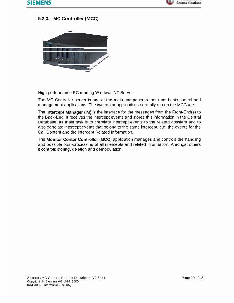
5.2.3. MC Controller (MCC)
High performance PC running Windows NT Server.
The MC Controller server is one of the main components that runs basic control andmanagement applications. The two major applications normally run on the MCC are:
The Intercept Manager (IM) is the interface for the messages from the Front-End(s) tothe Back-End. It receives the intercept events and stores this information in the CentralDatabase. Its main task is to correlate intercept events to the related dossiers and toalso correlate intercept events that belong to the same intercept, e.g. the events for theCall Content and the Intercept Related Information.
The Monitor Center Controller (MCC) application manages and controls the handlingand possible post-processing of all intercepts and related information. Amongst othersit controls storing, deletion and demodulation.

Siemens MC General Product Description V2.3.doc Page 30 of 48Copyright © Siemens AG 1999, 2000ICM CD IS (Information Security)
5.2.4. MC Database
High performance PC running Windows NT Server.
The MC Database server contains the central database of the Monitor Center Back-End. As standard MS SQL Server is used.
The database consists of several basic tables that contain:
- configuration parameters
- the definitions for dossiers, users, groups
- the definitions for triggers
- rights definitions
It also holds the Dossier Database, the intercept information and the references toinformation stored outside the database.
It is basically organized into
- Dossier specific tables containing the main intercept entries
- Intercept specific tables that contain information about the attachments that belongto an intercept (like a speech recording, a transcription, a decoded fax, etc.) andthe pointer/locator to the place, were the attachment is actually stored.
- Dossier specific configuration for rights, storage and archiving.

Siemens MC General Product Description V2.3.doc Page 31 of 48Copyright © Siemens AG 1999, 2000ICM CD IS (Information Security)
5.2.5. Storage System / Dossier Storage
High performance PC(s) running Windows NT Server.
The Storage System layout is highly depending on the system requirements,storage/archiving capacity, number of dossiers, etc. It may therefore consist of severalunits with several tasks and configuration.
A Storage System can basically be divided into two logical components:
- Storage Controller, a process that manages and controls Storage Units. Dependingon the system size, this component may run on a separate or the same machinethat runs Storage Unit(s). It offers intercept retrieval services and moves interceptsfrom the Front-End to storage unit(s).
- Storage Unit(s), that consist of storage/archiving volumes. A Storage Unit mayconsist of several archiving volumes in one unit or may only contain one volume inone unit. It provides a device independent volume interface to the StorageController. All device specific functions are hidden in the Storage Unit.
A Volume is a storage media. It can be a magneto optical disk (MOD) platter, adigital audio tape (DAT), a RAID, or a single disk drive (harddisc).
The solution for Dossier storage is to use discreet drives for each storage volume. Thestorage units consists of NT based machines which can have up to 8 discreetvolumes. The volumes may be harddisk drives (optional with RAID), Magneto OpticalDrives (MOD) or DAT drives. The dimensioning of the volumes (archiving capacity) isaccording to the requirements.
In special situations, one MOD platter can be used as a working storage medium whilea second one is used as a master copy (proof medium). †
An important feature of the Storage Unit is that each platter is permanently mounted ona drive. There is thus one drive per platter and platters are not swapped in and out ofdrives under software control.
† Available on special request

Siemens MC General Product Description V2.3.doc Page 32 of 48Copyright © Siemens AG 1999, 2000ICM CD IS (Information Security)
This has the following major advantages:
♦ Speed: Having one drive per platter means that the platter is always mounted anddata can be read and written continuously without ever having to wait for a platter tobe swapped in.
♦ Reliability: No jukebox robot swapping mechanism is needed, which eliminates amajor source of unreliability.
♦ Throughput: A limited number of volumes are connected per Storage Unit. Asmore Dossiers are needed, more Windows NT servers with optical drives areadded, but each new Storage Unit can handle the maximum data traffic requiredand the optical storage never becomes a throughput bottleneck as would be thecase of one centralized jukebox.
The whole system may be configured to consist of one Dossier, which implies that allintercepts will be stored on one virtual volume. In the case of Lawful Interception onevolume may be allocated to one Dossier. Archiving of intercepts will be performedautomatically.
The archived information is stored in standard file formats as there are WAVE formatfor audio files (speech), TIFF format for decoded fax images, TEXT format for log-files,transcriptions or text-based attachments like S-Records. Text formats include bothASCII text and RTF format.
5.2.5.1. Export of data from Dossier Storage
Through the Unified User Station, discussed in more detail further on, data may beexported from Dossier Storage to a local disk or e.g. a floppy disk.
Exported data will be saved in the standard computer formats as listed above.
5.2.5.2. Management of storage volumes
Storage volumes must be formatted before it can be used within the system. This is theresponsibility of the System Administrator. Unique volume labels with direct referenceto the relevant dossier as well as information uniquely identifying the volume areprovided for.
An indication in the form of an alarm informs the Administrator that a volume needsreplacement. Overflow is catered for but data cannot be overwritten in the case of astorage volume reaching capacity. A volume may be disabled and replaced.
Automatic label printing for MOD and DAT‡.
‡ available in 2000

Siemens MC General Product Description V2.3.doc Page 33 of 48Copyright © Siemens AG 1999, 2000ICM CD IS (Information Security)
5.2.5.3. Restoration of data
Archived can be restored back to the system for on-line availability. If not existinganymore in the system, the original dossier structure may be recreated duringrestoration.
Siemens MC General Product Description V2.3.doc Page 34 of 48Copyright © Siemens AG 1999, 2000ICM CD IS (Information Security)
5.2.6. Operator Station / Unified User Station ( UUS )
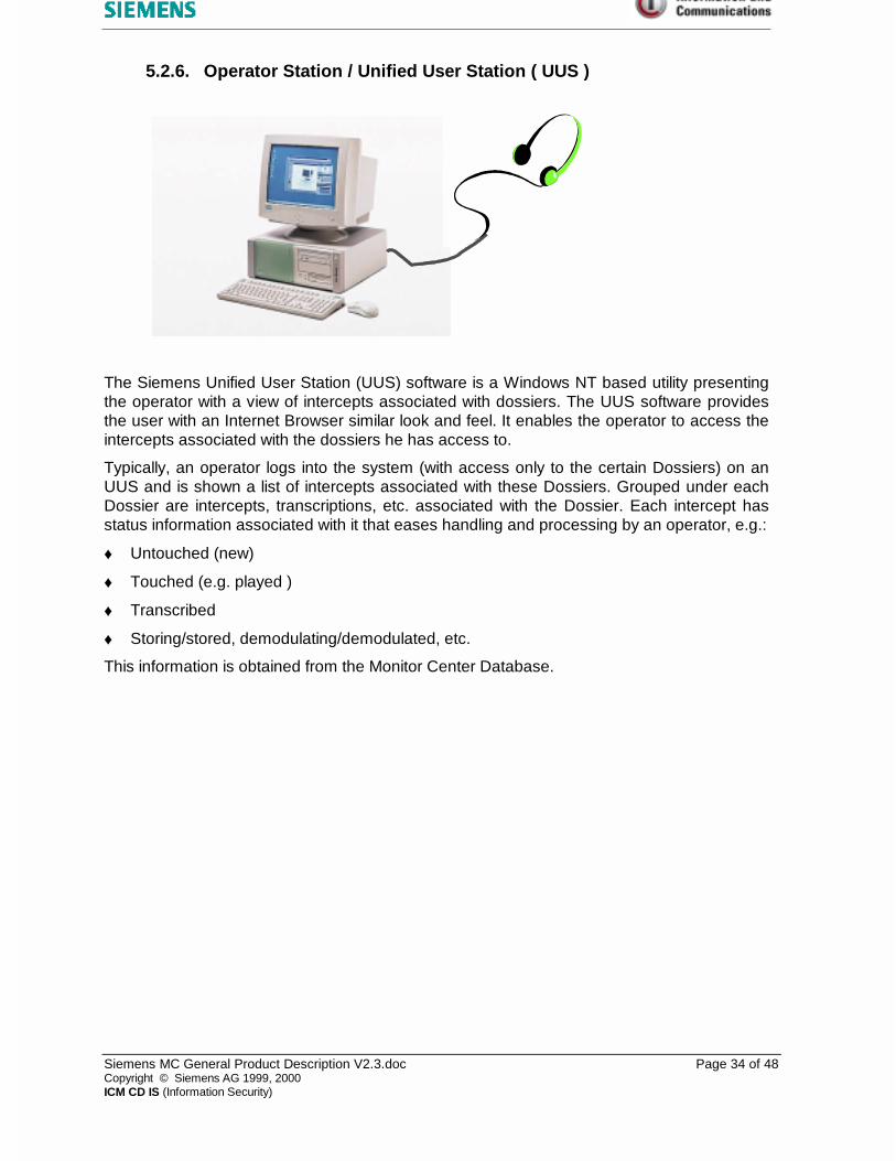
The Siemens Unified User Station (UUS) software is a Windows NT based utility presentingthe operator with a view of intercepts associated with dossiers. The UUS software providesthe user with an Internet Browser similar look and feel. It enables the operator to access theintercepts associated with the dossiers he has access to.
Typically, an operator logs into the system (with access only to the certain Dossiers) on anUUS and is shown a list of intercepts associated with these Dossiers. Grouped under eachDossier are intercepts, transcriptions, etc. associated with the Dossier. Each intercept hasstatus information associated with it that eases handling and processing by an operator, e.g.:
♦ Untouched (new)
♦ Touched (e.g. played )
♦ Transcribed
♦ Storing/stored, demodulating/demodulated, etc.
This information is obtained from the Monitor Center Database.

Siemens MC General Product Description V2.3.doc Page 35 of 48Copyright © Siemens AG 1999, 2000ICM CD IS (Information Security)
5.2.6.1. Playback
On selecting an intercept that contains a speech recording a graphical playbackwindow provides for playback control. Depending on the type of recording, playbackmight be either in mono or stereo.
Basic playback functions:
♦ Start
♦ Pause
♦ Rewind
♦ Fast forward (can be configured to jump in relative steps)
♦ Fast backward (can be configured to jump in relative steps)
♦ Playback cursor might be freely positioned directly at any position in the recording
♦ Window shows start and stop time and actual playback position
♦ The playback position can be shown as either an absolute or relative time value
♦ A portion of the recording might be marked for looped (repeated) playback
♦ Variable playback speed: ½ to 2 times real speed without pitch change
♦ Transcription during playback
♦ Often used functions also available via shortcut keys
5.2.6.2. Hot / On-Line Monitoring
While logged in, an operator may be notified of a high priority call that is just beingrecorded and by clicking on the notification, hot-monitoring playback may be done whilerecording is still in progress.
Hot-monitoring for a certain target will already be defined during target/trigger definition.
If such target becomes active, a hot-monitoring alarm is broadcasted. Each operatorhaving access rights to activities of that target can individually subscribe to receive thesehot-monitoring alarms. This also can be done for each dossier individually. Hot-monitoringalarms will show up in a separate window on the UUS.
As soon as an operator receives such an alarm, he immediately can start hot-monitoringthat activity. In the case of split stereo the operator may listen to one or both channelsdepending on what is immediately available. The source of the recording will be therecorder and not the Dossier Storage. An inherent delay of 3-4 sec. is present because ofhardware buffering.
The system is able to handle incoming calls/recordings while operators are listening andviewing intercepts from their UUS. This, however, will be the case within certain physicalrestraints such as processing speed and network bandwidth.
Siemens MC General Product Description V2.3.doc Page 36 of 48Copyright © Siemens AG 1999, 2000ICM CD IS (Information Security)
5.2.6.3. Fax Display
Provided that the Monitor Center is equipped with an optional Fax or Fax/Datademodulation system, recordings successfully demodulated and decoded will beavailable as a TIFF image file for direct viewing.
Using the built-in fax viewer, a fax image can be displayed, swapped, flipped, andzoomed via the Unified User Station.
It is also possible to configure the UUS to use an external fax viewer as default viewer.Thus special customer requirements can easily be satisfied.
Additional information pertaining to a fax (like modes, formats, etc.), will be stored in atext file that can be viewed with the built-in editor.
5.2.6.4. Transcription
It is possible to transcribe the recording into a word processor while listening to therecording. Transcription software packages supported currently are:
♦ Built-in TXT editor
♦ built-in RTF editor
♦ as default configurable external editor (e.g. Microsoft Word or Wordpad).External editor – if not part of the operating system – is optional.

Siemens MC General Product Description V2.3.doc Page 37 of 48Copyright © Siemens AG 1999, 2000ICM CD IS (Information Security)
5.2.7. Fax and data Demodulation
A system for Fax/data-Demodulation can be offered separately.
Once a fax or data transmission has been recorded and transferred to the StorageSystem, it must be demodulated and decoded to be able to display it. This is done bythe Siemens Fax Demodulator or by the Fax/Data Demodulation System. Onlytransmissions recorded at 64 kbit/s can be decoded successfully. After demodulationand decoding it is saved back to the Storage System from where it may be viewed.
Many Fax equipment manufacturers are not following the standards. They make use ofproprietary protocols for Fax transmissions between their equipment. Therefore, theFax/Data Demodulation System is also able to demodulate more than 1000 non-standard Fax protocols from different manufacturers. Please note, that some Faxesfrom no-name Fax machines might not be demodulated. A list of Fax machinemanufacturers that are supported can be provided on demand.
5.2.7.1. Siemens Fax Demodulator
The optional Fax Demodulator (using the Siemens Fax Demodulation software) has thefunctionality to demodulate identified fax transmissions stored on the Storage System.Such transmissions are retrieved from Dossier Storage, demodulated, decoded andstored on the Dossier Storage in the form of viewable .TIF documents.
The Siemens Fax Demodulator is a Win32 system that runs on a high speed WindowsNT platform. It demodulates standard G3 Faxes at about three times of the realspeed. These units need to be operated in parallel in situations where large numbers offaxes must be handled.

Siemens MC General Product Description V2.3.doc Page 38 of 48Copyright © Siemens AG 1999, 2000ICM CD IS (Information Security)
5.2.7.2. Fax/Data Demodulation System
This optional System consists of special hardware and software and can demodulateFax and Data transmissions. More than 1000 non-standard Fax protocols from differentmanufacturers are supported.
Information on the training phase is extracted and stored for later analysis. Thisinformation includes the following:
♦ Handshake information
♦ Manufacturer of the fax equipment
♦ Type of coding (error Correction Mode, etc.)
Also Internet data transmissions between a subscriber (target) and the Internetprovider can be demodulated and viewed. This allows the LEA to monitor and view theInternet session of the target (offline), like the target saw it online, except sessionactivities of the target which did not result in a communication activity (i.e. use ofdata/programs already active in computer cache memory).
For further information please ask for separate document.

Siemens MC General Product Description V2.3.doc Page 39 of 48Copyright © Siemens AG 1999, 2000ICM CD IS (Information Security)
5.2.7.3. Manual or automatic data analysis
If Fax/data demodulation equipment is part of a Monitor Center the system can beconfigured for automatic demodulation of all fax/data transmissions (recognized andmarked as such).
It is also possible to demodulate and decode transmissions on request, i.e., theoperator can decide, which intercept shall be demodulated.
The second possibility might be helpful, when only limited demodulation capacity isavailable or to force a demodulation for an intercept that was not recognizedautomatically as a fax or data transmission during recording.

Siemens MC General Product Description V2.3.doc Page 40 of 48Copyright © Siemens AG 1999, 2000ICM CD IS (Information Security)
6. ALARMS
Alarm conditions may occur throughout the Monitor Center and its individual components.Alarms can be handled in a number of ways.
Alarms of all components are provided as far as possible centrally. The system runs anAlarm Server that receives alarms from the system components and broadcasts them on theLAN.
Alarm Viewers can be installed anywhere in the system (e.g. on Management or OperatorStations) and each Alarm Viewer can be configured individually to listen only to certain or toall alarms, i.e., each specific alarm can be "subscribed" for.
Each alarm subscription can be defined individually to generate an audible alarm, to onlycreate an entry in the alarm list or to pop-up an alarm window.

Siemens MC General Product Description V2.3.doc Page 41 of 48Copyright © Siemens AG 1999, 2000ICM CD IS (Information Security)
7. EVENT LOGGING
Every event in the Siemens Monitor Center can theoretically be logged.
It is widely possible to specify which events should be logged. These logs can be viewed foranalysis of activities or identification of possible bottlenecks and problems.

Siemens MC General Product Description V2.3.doc Page 42 of 48Copyright © Siemens AG 1999, 2000ICM CD IS (Information Security)
8. MC SECURITY
8.1. DOSSIER STORAGE FILE SECURITY
The security of data stored in the MC Back-End is based on NT security. Standard NTgroup and user rights control access to files stored in the Storage System.
8.2. DATABASE SECURITY
Access to the database is allowed through interfaces, which relies on NT security. Anyperson or process without sufficient user rights access will be denied.
8.3. PHYSICAL SECURITY
Password security is based on the NT security model which include:
♦ Minimum length passwords
♦ Password history
♦ Validity period of passwords are specified
♦ Unsuccessful logins limited
In cases where operators access the system from remote sites, third party authenticationand security techniques may be used such as dial-back, encrypted links, etc..
Third party products for additional physical security may also be used, like chip cardreaders for access. They will not influence the system operation.

Siemens MC General Product Description V2.3.doc Page 43 of 48Copyright © Siemens AG 1999, 2000ICM CD IS (Information Security)
9. SCALABILITY
The Monitor Center is scaleable from a small system consisting of a single recording unit andsingle Back-End Windows NT Server PC to a theoretically unlimited size.
The functionality is isolated into functional units. This allows for further scalability in thesystem. Examples of such optional units are:
♦ New Front-Ends
♦ Fax/modem demodulation and decoding
♦ Extension of the Storage System

Siemens MC General Product Description V2.3.doc Page 44 of 48Copyright © Siemens AG 1999, 2000ICM CD IS (Information Security)
10. RELIABILITY
10.1. SYSTEM TIME
The system can optionally be time synchronized based on DCF77 (Europe) or GPS(international). All sub-systems can be time synchronized. The recorders aresynchronized with an accuracy of 10 ms. This is essential in cases where split stereorecordings are made on different recorders. All events are time stamped using the systemtime.
10.2. POWER SUPPLY
♦ Support of UPS and automatic shutdown on detection of power loss (optional)
♦ Two power supplies, Hot Plug (optional)
10.3. THERMAL CONTROL
The CPUs in the recorders are continuously cooled by fan and the CPUs in the rackmounted units are thermal controlled. In addition the racks are ventilated by forced air.
10.4. MIRRORING OF DATA
The design of a Siemens Monitor Center is flexible. Optionally it can be adapted to mirrorall essential data in the recorders and/or in the Back-End by RAID systems.
10.5. MAINTAINABILITY
The Back-End or components of it can be maintained and even switched off withoutinterrupting recording activity. Intercepts will be buffered on the recorders until the Back-End is online again.

Siemens MC General Product Description V2.3.doc Page 45 of 48Copyright © Siemens AG 1999, 2000ICM CD IS (Information Security)
11. UPGRADIBILITY
Drivers and subsystems are developed in such a way as to allow for easy upgrades offeatures and functionality.
It is possibility to upgrade the Back-End without interrupting recording activity. Intercepts willbe buffered on the recorders until the Back-End is online again.

Siemens MC General Product Description V2.3.doc Page 46 of 48Copyright © Siemens AG 1999, 2000ICM CD IS (Information Security)
12. TARGET ADMINISTRATION
12.1. PASSIVE MONOITORING
In case of passive monitoring the LEA has no direct access to the switch therefore themarking of targets (Triggers) has to be done within the Siemens Monitor Center. Withinthe MC Manager application there is a possibility to enter Triggers. These lists of Triggersare automatically transferred to the Recording Controller of the passive Front-End. Basedon this Trigger information the Recording Controller decides which call has to be recordedand therefore switches a certain input stream/channel to one available recording channelon the AQ using the DVX.
12.2. ACTIVE MONITORING
The administration of marked subscribers, e.g. enter new interception decision, is doneusing an administration workstation. In general there is no difference betweenadministration of a mobile or fixed network switch. In a fixed network it is only possible tomark the telephone number of a subscriber whereas in a mobile network it is also possibleto mark IMSI, IMEI of a subscriber, if this feature is supported by the switch supplier.Additionally it is possible to do a location based monitoring. This means all subscriberstemporarily located within a certain area (LAC) are monitored.
In order to send commands the administration workstation is connected via the X.25network to the switches.Because of the roaming capability of mobile subscribers onesingle subscriber has to be marked in each single MSC within a PLMN.
AdministrationWorkstation
Switch 1
X.25
Switch nAdmin command (switch n)
Admin command (switch 1)

Siemens MC General Product Description V2.3.doc Page 47 of 48Copyright © Siemens AG 1999, 2000ICM CD IS (Information Security)
13. MULTI MONITORING SETUP
Multi monitoring is necessary if more than one LEA want to use the monitoring functionalitywithin a telephone network, no matter if fixed or mobile network.
13.1. PASSIVE MONITORING
Passive monitoring also known as trunk monitoring is realised by tapping into the trunklines using high impedance coupling devices. If a second LEA also wants to monitor atrunk line already under investigation by another LEA , a second coupling device has tobe installed at this particular trunk line. This has no influence neither on the administrationnor on the passive Front-End in the Monitor Center.
13.2. ACTIVE MONITORING
In case of active monitoring (this means a subscriber is directly marked within the switch)one subscriber can be marked by more than one LEA simultaneously. In order to provideall LEAs with the functionality of marking subscribers independently each LEA will have it’sown remote terminal connected to one master administration workstation. It is assuredthen that both LEAs will not see each other's marked targets on their remote terminals.Also it will not happen that in case a target is deleted by one LEA it will also be deleted forthe other LEA.
For more than one LEA both Call Content (CC) as well as Intercept Related Information(IRI) of an intercepted call has to be forwarded to all MCs having marked this particularsubscriber.
For the Call Contend the switch either mobile or fixed network has to multiply it andforward the call to each MC. Depending on the supplier and software release of the switchthis functionality is built-in or additional hardware is needed.
Concerning the IRI the switch sends only one S-Record to the master administrationworkstation (e.g. ICC, LIOS). The administration workstation duplicates the S-Record andsends a copy to each MC having marked this particular subscriber.

Siemens MC General Product Description V2.3.doc Page 48 of 48Copyright © Siemens AG 1999, 2000ICM CD IS (Information Security)
14. DOCUMENT REVISION HISTORY
Revision Date Author
1.0 10/06/1998 Siegfried Neubauer PN KE IS PV
1.1 04/08/1998 Siegfried Neubauer PN KE IS PV
1.2 10/08/1998 Siegfried Neubauer PN KE IS PV
1.3 01/10/1998 Siegfried Neubauer PN KE IS PV
1.4 30/10/1998 Siegfried Neubauer PN KE IS PV
1.5 19/02/1999 Manfred Büttner ICP CD CT IS V
1.6 25/02/1999 Rumscheidt / Nissen ICP CD CT IS
2.0 04/03/1999 Nissen ICP CD CT IS
2.1 04/03/1999 Neubauer ICP CD CT IS
2.1.1 15/10/1999 Pörsch ICP CD IS
2.1.2 30/11/1999 Eisenschmid ICP CD IS
2.2 11/01/2000 Rumscheidt ICP CD IS S
2.2.1 09/02/2000 Büttner ICP CD IS S
2.3 12/05/2000 Büttner ICM CD IS S / Eisenschmid ICM CD IS PM
Copyright © Siemens AG 1999, 2000All rights reserved. No part of this document may be reproduced or utilized in any form or anymeans, electronic or mechanical, including photocopying, recording, or any informationstorage or retrieval system, without permission in writing from the author.


