SIGNING, PAVEMENT MARKING AND LIGHTING SECTION 700 HIGHWAY SIGNING 700-1 General Requirements. 700-1.1 Description: Furnish and erect roadway signs at the locations, and in accordance with the details, shown in the Plans. The Department designates ground traffic signs as signs erected on the shoulders, slopes, or medians, but not extending over the traveled roadway, and may further classify these signs as single post or multi-column. The Department designates signs erected partially or completely over the traveled roadway or mounted on bridges as overhead traffic signs, and may further classify these signs as overhead cantilever or span traffic signs. Meet the requirements of Section 603. 700-1.2 Materials: 700-1.2.1 General: Meet the materials requirements shown in the Specifications and Design Standards and any additional requirements identified in the Plans. 700-1.2.2 Concrete: Use concrete meeting the requirements of Section 346. Obtain concrete from a plant that is listed on the Department’s Production Facility Listing. Producers seeking inclusion on the list shall meet the requirements of Section 105. 700-1.2.3 Static Sign Assembly Requirements: All sign panels shall be aluminum unless otherwise shown in the Plans. Sheets and plates for sign panels shall meet the requirements of ASTM B209, Aluminum Association Alloy 6061-T6, 5154-H38 or 5052-H38. Sign panels for single column ground mounted signs shall utilize aluminum plate with a minimum thickness of 0.08 inches. All other sign panels shall utilize aluminum plate with a minimum thickness of 0.125 inches. All panels shall have rounded corners. 700-1.2.4 Retroreflective Sign Sheeting: Use signs that meet the material and process requirements of Section 994. Use Type XI sheeting for all regulatory, warning and overhead signs. The R1-1, R1-2, R5-1 and R5-1a signs must use a sheeting system that includes a colorless film overlay. Type XI sheeting shall also be used for all limited access advance exit and exit guide signs. Use Type IV yellow-green fluorescent sheeting for school S1-1, S3-1, S4- 3, S4-5 and supplemental panels used with S1-1 signs. Do not mix signs having fluorescent yellow-green sheeting with signs having yellow retroreflective sheeting. Roll-up signs shall meet the requirements of Type VI sheeting. Use Type IV sheeting for all other signs. 700-1.3 Sign Fabrication Requirements: Obtain multi-post and overhead sign structures from a facility that is listed on the Department’s Production Facility Listing. Producers seeking inclusion on the list shall meet the requirements of Section 105. 700-1.4 Storage, Handling and Labeling: If signs are stored prior to installation, store them in accordance with the manufacturer’s recommendations. Properly package signs to protect them during storage, shipment and handling to prevent damage to the sign face and panel. In addition to the information required in Section 994, all permanent roadway signs must be labeled on the back bottom edge with the date of installation. Make the labels
Transcript
SIGNING, PAVEMENT MARKING AND LIGHTING
SECTION 700 HIGHWAY SIGNING
700-1 General Requirements. 700-1.1 Description: Furnish and erect roadway signs at the locations, and in accordance with the details, shown in the Plans. The Department designates ground traffic signs as signs erected on the shoulders, slopes, or medians, but not extending over the traveled roadway, and may further classify these signs as single post or multi-column. The Department designates signs erected partially or completely over the traveled roadway or mounted on bridges as overhead traffic signs, and may further classify these signs as overhead cantilever or span traffic signs. Meet the requirements of Section 603. 700-1.2 Materials: 700-1.2.1 General: Meet the materials requirements shown in the Specifications and Design Standards and any additional requirements identified in the Plans. 700-1.2.2 Concrete: Use concrete meeting the requirements of Section 346. Obtain concrete from a plant that is listed on the Department’s Production Facility Listing. Producers seeking inclusion on the list shall meet the requirements of Section 105. 700-1.2.3 Static Sign Assembly Requirements: All sign panels shall be aluminum unless otherwise shown in the Plans. Sheets and plates for sign panels shall meet the requirements of ASTM B209, Aluminum Association Alloy 6061-T6, 5154-H38 or 5052-H38. Sign panels for single column ground mounted signs shall utilize aluminum plate with a minimum thickness of 0.08 inches. All other sign panels shall utilize aluminum plate with a minimum thickness of 0.125 inches. All panels shall have rounded corners. 700-1.2.4 Retroreflective Sign Sheeting: Use signs that meet the material and process requirements of Section 994. Use Type XI sheeting for all regulatory, warning and overhead signs. The R1-1, R1-2, R5-1 and R5-1a signs must use a sheeting system that includes a colorless film overlay. Type XI sheeting shall also be used for all limited access advance exit and exit guide signs. Use Type IV yellow-green fluorescent sheeting for school S1-1, S3-1, S4-3, S4-5 and supplemental panels used with S1-1 signs. Do not mix signs having fluorescent yellow-green sheeting with signs having yellow retroreflective sheeting. Roll-up signs shall meet the requirements of Type VI sheeting. Use Type IV sheeting for all other signs. 700-1.3 Sign Fabrication Requirements: Obtain multi-post and overhead sign structures from a facility that is listed on the Department’s Production Facility Listing. Producers seeking inclusion on the list shall meet the requirements of Section 105. 700-1.4 Storage, Handling and Labeling: If signs are stored prior to installation, store them in accordance with the manufacturer’s recommendations. Properly package signs to protect them during storage, shipment and handling to prevent damage to the sign face and panel. In addition to the information required in Section 994, all permanent roadway signs must be labeled on the back bottom edge with the date of installation. Make the labels
unobtrusive, but legible enough to be easily read by an observer on the ground when the sign is in its final position. Apply the label in a manner that is at least as durable as the sign face. 700-1.5 Acceptance of Signs: 700-1.5.1 Sign Inspection: Provide certification that the sign assembly meets the material and installation requirements of the Contract Documents. The Engineer will inspect the signs upon delivery to the storage or project site and again at the final construction inspection. Repair and replace signs deemed unacceptable by the Engineer at no expense to the Department. 700-1.5.2 Imperfections and Repairs: Repair or replace signs containing imperfections or damage regardless of the kind, type, or cause of the imperfections or damage. For sign panels exceeding 30 square feet, the Contractor may make one patch, if necessary, to each sign panel not to exceed two square inches. Make repairs according to the manufacturer’s recommendations and to the satisfaction of the Engineer. Ensure that completed repairs provide a level of quality necessary to maintain the service life of the sign and are satisfactory in appearance to the Engineer.
700-2 Static Signs. 700-2.1 Ground Mounted Signs: Ground mounted signs consist of both single column and multi-column static signs. 700-2.1.1 Materials: Use aluminum tubing materials meeting the general provisions of Section 965 for all single column ground signs. Multi-column signs must be galvanized steel W or S beams steel columns meeting the general provisions of Section 962. All materials must meet the requirements of the appropriate Design Standard. 700-2.1.2 Fabrication of Panel Messages: Fabricate standard sign panel messages in accordance with details included in the Standard Highway Signs (SHS) manual published by the U.S. Department of Transportation. Submit shop drawings to the Department for approval as specified in Section 5. 700-2.1.3 Foundation: Construct foundations in accordance with the applicable Design Standards. The Contractor may use precast foundations in augured or excavated holes a minimum of 12 inches larger than each axis dimension of the precast foundation. Obtain precast foundations from a plant that is currently on the Department’s Production Facility Listing. Producers seeking inclusion on the list shall meet the requirements of Section 105.The holes must be clean and without loose material. Temporary casing will be required if the soil is unstable. Fill the void around the precast foundation with flowable fill meeting the requirements of Section 121 or use clean sand placed using hydraulic methods. 700-2.1.4 Breakaway Support Mechanisms for Ground Traffic Signs: 700-2.1.4.1 Frangible Supports: Provide support posts for all frangible sign assemblies consisting of aluminum tubes up to 3 -1/2 inches outside diameter with 3/16 inch wall thickness in accordance with the requirements in the Design Standards. 700-2.1.4.2 Slip Bases: Slip base assemblies for single column signs will use aluminum sleeves and base plates. Slip base assemblies for multi-column signs will use galvanized steel bases. All slip bases must be fabricated in accordance with the requirements of the Design Standards. 700-2.1.5 Installation: Verify the length of the column supports in the field prior to fabrication to permit the appropriate sign mounting height. Fabricate the supports and wind beams in accordance with the Design Standards. Columns must be plumb and panels must be level with the proper orientation.
700-2.1.6 Retroreflective Strips for Signs: Use only on signs where the retroreflective sign strip is called for in the Plans. Use 0.040 aluminum panels, Type IV or Type XI retroreflective sign sheeting meeting the requirements of Section 994 for the fabrication of the retroreflective sign strips and stainless steel attachment hardware for the installation. Retroreflective sign strips must be 2 inches in width and a height of 5 feet for all signs except for when signs are mounted at 4 feet, then retroreflective sign strip will be 2 feet in height. For the back of Rail Road Crossbuck signs, the retroreflective sign strip will be 2 inches wide for the full length of the blade. Match the color of the retroreflective sheeting to the background color of the sign except for YIELD signs and DO NOT ENTER signs, where the color must be red. 700-2.2 Overhead Signs: 700-2.2.1 Materials: 700-2.2.1.1 General: Obtain reinforcing steel, multi-post and overhead sign structures from a fabrication facility that is listed on the Department’s Production Facility Listing. Producers seeking inclusion on the list shall meet the requirements of Section 105. Only use structural steel, including bolts, nuts, and washers, that have been hot dip galvanized or metalized after fabrication. Perform hot dip galvanizing in accordance with Section 962 and metalizing in accordance with Section 562. For galvanized steel members, meet the general requirements of Section 962. Obtain galvanized steel from a fabrication facility that is listed on the Department’s Production Facility Listing. Producers seeking inclusion on the list shall meet the requirements of Section 105. Use a galvanizing compound as specified in Section 975. Use a galvanizing repair compound listed on the APL for large areas as defined in Section 975. 700-2.2.1.2 Reinforcing Steel: Use reinforcing steel in footings meeting the requirements of Section 415. 700-2.2.1.3 Specific Uses of Aluminum and Galvanized Steel: Use aluminum bolts, nuts, and hardware to connect parts of the cast base. Use galvanized steel anchor bolts for anchoring base plates to concrete bases and for the nuts and washers. For all other metal parts of the cast base, the Engineer will allow galvanized steel as an alternative to aluminum. 700-2.2.2 Foundations: Meet the requirements of Section 455. 700-2.2.3 Installation: Install nuts on anchor bolts in accordance with Section 649 with the following exception. For cantilever overhead sign structures, after placement of the upright and prior to installation of the truss, adjust the leveling nuts beneath the base plate to achieve the back rake shown on the Camber Diagram. If the top surface of the base plate has a slope that exceeds 1:40, use beveled washers under the top nuts. For span overhead sign structures, install a screen around the base plate in accordance with 649-6. For cantilever overhead sign structures, install a structural grout pad in accordance with 649-7. Install ASTM A325 bolt, nut and washer assemblies in accordance with 460-5, except that 460-5.4.2 Preparation of Faying Surfaces is not required. 700-2.2.4 Erection of Signs and Sign Supports: Do not erect overhead sign supports until the concrete strength in the support footing is at least 2,500 psi. Determine concrete strength from tests on a minimum of two test cylinders sampled and tested in accordance with ASTM C31 and ASTM C39 and verifying test results have been provided to the Engineer.
Erect the signs and sign structures in accordance with the details shown in the Plans. The Contractor may fabricate the structural steel sign trusses in sections that will fit into available galvanizing vats. Prior to galvanizing, weld the joints as specified in Section 460 and in accordance with the details shown in the Plans. Re-galvanize damaged parts as specified in Section 562. Weld aluminum structures in accordance with Section 965. Attach electronic display signs to the supporting structure in accordance with the manufacturer’s recommendations using the mounting hardware provided by the manufacturer. 700-2.2.5 Shop Drawings: Submit shop drawings to the Department for approval as specified in Section 5. Prior to the submittal of the shop drawings, determine the actual in-place dimensions for all sign structures on the basis of existing field conditions and include these on the shop drawings. 700-2.3 Method of Measurement: For single post and multi post sign assemblies, an assembly consists of all the signs mounted on a single structure. The Contract unit price per assembly for ground mounted signs (single post and multi-post), furnished and installed, will include furnishing the sign panels, support structure, foundation, hardware, and labor necessary for a complete and accepted installation. The retroreflective sign strip will be paid for separately, and the Contract unit price per each will include furnishing the retroreflective sign strip, hardware and labor necessary for a complete and accepted installation. For overhead signs, sign panels will be paid separately from support structures. The Contract unit price per each for sign panel, furnished and installed, will include furnishing the sign panels, hardware, and labor necessary for a complete and accepted installation. The Contract unit price for each overhead static sign structure, furnished and installed, will include furnishing the support structure, foundation, hardware, and labor necessary for a complete and accepted installation. Relocation of signs will consist of removing the existing sign assembly and installing the sign on a new foundation at the location shown in the Plans. When the Plans call for existing ground-mounted signs to be relocated or removed, after removing the sign panel from the assembly, remove supports and footings. Restore the area of the sign removal or relocation to the condition of the adjacent area. 700-2.4 Basis of Payment: Price and payment will be full compensation for all work specified in this Section. Payment will be made under:
Item No. 700- 1- Single Post Sign, per Assembly. Item No. 700- 2- Multi Post Sign, per Assembly. Item No. 700- 3- Sign Panel, per Each. Item No. 700- 4- Overhead Static Sign Structure , per each. Item No. 700- 13 Retroreflective Sign Strip, per each.
700-3 Illuminated Signs. 700-3.1 Description: Furnish and install illuminated signs in accordance with the details specified in the Contract Documents. 700-3.2 Materials: Use illuminated signs and associated mounting hardware listed on the Department’s Approved Product List (APL).
Signs must be marked with the name or trademark of the manufacturer, the part number, and the date of manufacturer. Marking must be accomplished by permanently affixing an indelible label, identification plate, dot peen type stamp, casting, metal-marking, or other approved method. Markings must remain visible after installation. 700-3.2.1 Internally Illuminated Signs: 700-3.2.1.1 General: Signs must not exceed 9 feet in length or be larger than 18.0 square feet in area, and must not weigh more than 144 pounds. Provide an internally illuminated sign assembly listed to the requirements of UL48. Light emitting diode (LED) retrofit kits must be listed on the APL. 700-3.2.1.2 Housing: Ensure that the sign housing is constructed of continuous 5052 or 6063-T5 aluminum. All housing, corners, and door seams must be continuously welded. All exterior surfaces of the assembly must be powder-coat painted in accordance with Military Standard MIL-PRF-24712A or AAMA-2603-02. Finish must meet the requirements of ASTM D3359, ASTM D3363, and ASTM D522. Sign housings with any interior airspace must consist of a box type enclosure and separate hinged door assembly. The sign housing must include provisions to prevent water from entering the sign housing. Drain holes in the sign larger than 0.125 inch must be covered by a screen. Signs must have removable sign faces. The sign assembly must have one face unless specified otherwise in the Plans. The sign face must be secured by a method that holds the sign face securely in place. Slide-in grooves are allowed to secure the sign face if the sign is edge lit. The sign face must be a translucent lens constructed of 0.125 inch thick high impact strength polycarbonate or acrylic meeting UL48. Letters must be as detailed in the Contract Documents. Background must be translucent retroreflective sheeting coated with a transparent, pressure-sensitive adhesive film. Color must meet the criteria as detailed in Sections 994. Retroreflective sheeting must meet the requirements of Section 994, and be listed on the APL. If a door opens upward, it shall have a bracket on each side to secure the door in the open position during maintenance. Doors shall be permanently and continuously sealed with a foam gasket listed to UL157 to prevent the entry of water into the sign housing. Each door must be secured from opening by a minimum of two stainless steel rotary action draw latches. The sign assembly must be designed and constructed to withstand 150 mph wind loads meeting the requirements of the Department’s Structures Manual. 700-3.2.1.3 Luminance: The sign face must be illuminated evenly across the entire surface. Contrast ratio between the background and legend shall be established by the lowest and the highest color retroreflective measurement and shall be at least 4:1. Measure the retroreflectivity in accordance with ASTM D4956. 700-3.2.1.3.1 Background Luminance: Minimum luminance for the legend portion of the street sign face shall be no less than 87.5 lux. The luminance shall be determined by averaging a minimum of seven readings. Four of the readings shall be taken near the midpoint of a line that would span between the outside corners of the background and the outside corners of the legend. One reading shall be taken near the midpoint of a line that would connect the top corner readings. One reading shall be taken near the midpoint of a line that would connect the bottom corner readings. One reading shall be taken near the vertical and horizontal midpoint of the sign.
700-3.2.1.3.2 Border and Lettering Luminance: Minimum luminance of the legend and border shall be 350 lux. The luminance shall be determined by averaging a minimum of 17 readings. There shall be a minimum of one reading from each letter in the legend. Readings within the legend shall alternate between the top, middle and bottom portion of each letter. Readings within top and bottom of the border shall be perpendicular to the top and bottom readings in the background. Readings within the sides of the border shall be taken parallel to the readings taken within each letter. 700-3.2.1.4 Clamp-On Cantilever Arm: Use only clamp-on cantilever arms which meet all design and wind loading requirements as specified in the Contract Documents. Ensure the clamp is adjustable to accommodate various size poles. 700-3.2.2 Highlighted Signs: 700-3.2.2.1 General: Ensure highlighted signs meet the design and functional requirements specified in this Section and Section 2A of the MUTCD. Use LEDs to highlight the sign’s shape, color, or message. Stop, Do Not Enter, Yield, and Wrong Way signs that are highlighted with LEDs must use red LEDs. All other signs must use LEDs which resemble the color of the sign background color. 700-3.2.2.2 Performance Requirements: Ensure highlighted signs are capable of automatically dimming to reduce brightness of the LEDs at nighttime. Ensure highlighted signs that rely upon solar power or batteries are capable of at least 10 days of continuous operation without the need for charging. 700-3.2.3 Cabinets: If the illuminated sign assembly includes a cabinet, the cabinet must be currently listed on the APL or meet the applicable cabinet material requirements listed in Section 676. 700-3.2.4 Mechanical Requirements: Ensure all assembly hardware, including nuts, bolts, external screws and locking washers less than 5/8 inch in diameter are Type 304 or 316 passivated stainless steel. All assembly hardware greater than or equal to 5/8 inch in diameter must be galvanized. Bolts, studs, and threaded rod must meet ASTM A307. Structural bolts must meet ASTM A325. 700-3.2.5 Electrical Requirements: Electrical wiring must meet NEC requirements for the light source provided. All wiring must be copper wire. All internal electrical wiring must be tight and secure. Ensure the sign includes an accessible electrical power service entrance compartment (internal or external) for connection of field wiring. External compartments must be weather-tight. All power supplies and ballasts must be Federal Communications Commission (FCC) approved. Ensure electrical connections are protected against corrosion. All signs must have provisions for an integrated photocell. 700-3.2.6 Environmental Requirements: Ensure that the illuminated sign assembly operates properly during and after being subjected to the environmental testing procedures described in NEMA TS 2, Sections 2.2.7, 2.2.8, and 2.2.9. 700-3.2.7 Acceptance of Internally Illuminated Signs: Certify that signs and clamp-on cantilever arms provided meet the criteria in this Section. 700-3.3 Installation of Internally Illuminated Signs: 700-3.3.1 General: Secure the brackets to the sign housing in accordance with the manufacturer’s instructions.
700-3.3.2 Single Sided Sign Assembly: Install as specified in the Contract Documents. 700-3.3.3 Double Sided Sign Assembly: Use a free swinging mounting method. 700-3.3.3.1 Two Point Support Assembly: Use a two point support assembly when the sign assembly is attached to a mast arm that is perpendicular to the street on which the sign is viewed. Use a two point mast arm mounting assembly consisting of the following: 1. Stainless steel band or cable type clamp, 2. Clevis, 3. Span wire adapter, 4. Tri-stud hanger body. Ensure one of the hangers has a mechanism for the horizontal adjustment of the sign. 700-3.3.3.2 One Point Support Assembly: Use a one point support assembly consisting of an articulated horizontal stainless steel band or cable type mast arm clamp, sign bracket and mounting hardware, when the sign assembly is attached to a mast arm that is diagonal to the street on which the sign is viewed. Do not use a one point support assembly for internally illuminated sign assemblies exceeding four feet in width. Ensure the band or cable clamp is capable of horizontal rotation of 360 degrees. 700-3.3.3.3 Clamp-On Cantilever Arm: Attach the arm perpendicular to the street on which the sign assembly is viewed. Use a clamp and arm that are galvanized in accordance with ASTM A123 unless otherwise shown in the Plans. Ensure the arm has a cap secured in place. 700-3.3.4 Electrical Wiring: Unless otherwise shown in the Plans, install dedicated 14 AWG conductors to supply power to the sign and connect the conductors to a dedicated 15 amp circuit breaker located either inside the controller cabinet or inside the electrical service disconnect. Using the same conduit system for both signal cables and internally illuminated sign conductors is permitted, unless otherwise shown in the Plans. Install conductors in such a manner as to prevent damage to conductors or conductor insulation. Remove and replace all damaged conductors /insulation at no additional cost to the Department. Ensure drilled holes through which conductors pass through are fitted with a weather tight rubber grommet fitting. Install continuous lengths of conductors between the dedicated circuit breaker and internally illuminated signs. Do not splice conductors unless otherwise shown in the Plans. Provide one photoelectric cell for all internally illuminated signs at each intersection. Use an L bracket to mount the photoelectric cell as specified in the Contract Documents. Connect the photoelectric cell to a contactor assembly inside the controller cabinet to provide switching of the internally illuminated signs. 700-3.3.5 Warranty: 700-3.3.5.1 Internally Illuminated Signs: Ensure that internally illuminated signs have a manufacturer’s warranty covering defects for five years from the date of final acceptance by the Engineer in accordance with 5-11 and Section 608.
700-3.3.5.2 Highlighted Signs: Ensure that highlighted signs have a manufacturer’s warranty covering defects for three years from the date of final acceptance by the Engineer in accordance with 5-11 and Section 608. 700-3.4 Method of Measurement: The Contract unit price per each for internally illuminated signs, furnished and installed, will include furnishing the sign panels, housing, hardware, electrical connection, and labor necessary for a complete and accepted installation. When the internally illuminated sign is ground mounted, the Contract price will include the support structure and foundation. All other mounting will include the hardware necessary to complete the attachment to the support structure; the span wire, monotube, or mast arm structure will be paid separately. The Contract unit price per each for highlighted signs, furnished and installed, will include furnishing the sign panels, support structure, foundation, hardware, solar panel, and labor necessary for a complete and accepted installation. 700-3.5 Basis of Payment: Price and payment will be full compensation for all work specified in this Section. Payment will be made under:
Item No. 700- 5- Internally Illuminated Signs, per each. Item No. 700- 6- Highlighted Signs, per assembly.
700-4 Dynamic Message Signs. 700-4.1 General: Dynamic Message Signs (DMS) must meet the requirements of NEMA TS4-2005. DMS are classified by the type of sign display and the type of mechanical construction. Provide monochrome, tri-color, or full-color signs as shown in the Contract Documents. Use only equipment and components that meet the requirements of these minimum specifications and are listed on the APL. DMS LED retrofit kits must be listed on the APL. 700-4.1.1 Front Access DMS: Ensure that front access signs meet the requirements of NEMA TS 4-2005, Section 3.2.5. 700-4.1.2 Walk-In DMS: Ensure that walk-in signs meet the requirements of NEMA TS 4-2005, Section 3.2.7. 700-4.1.3 Embedded DMS: Embedded DMSs are typically mounted to ground traffic signs, overhead traffic signs, or overhead cantilever traffic signs. 700-4.2 Sign Housing Requirements for all DMS: Ensure that the external skin of the sign housing is constructed of aluminum alloy 5052 H32 that is a minimum of 0.125 inches thick for a walk-in DMS and 0.090 inch thick a for front or embedded DMS. Ensure the interior structure is constructed of aluminum. Ensure that the sign housing design and appearance is approved by the Engineer. Ensure that no internal frame connections or external skin attachments rely upon adhesive bonding or rivets. Ensure the sign enclosure meets the requirements of NEMA TS 4-2005, Section 3.1.1. Ensure that all drain holes and other openings in the sign housing are screened to prevent the entrance of insects and small animals. Ensure that the sign housing complies with the fatigue resistance requirements of the AASHTO Standard Specifications for Structural Supports for Highway Signs, Luminaires, and Traffic Signals, Fifth Edition (2001) with current addendums. Design and construct the DMS unit for continuous usage of at least 20 years and the sign structure for a 50 year design life. The sign assembly must be designed and constructed to withstand loads, including a wind load of 150 miles per hour, as defined in the Department’s Structures Manual.
Ensure that the top of the housing includes multiple steel lifting eyebolts or equivalent hoisting points. Ensure hoist points are positioned such that the sign remains level when lifted. Ensure that the hoist points and sign frame allow the sign to be shipped, handled, and installed without damage. Ensure all assembly hardware, including nuts, bolts, screws, and locking washers less than 5/8 inch in diameter, are Type 304 or 316 passivated stainless steel and meet the requirements of ASTM F593 and ASTM F594. All assembly hardware greater than or equal to 5/8 inch in diameter must be galvanized and meet the requirements of ASTM A307. Ensure all exterior, excluding the sign face, and all interior housing surfaces are a natural aluminum mill finish. Ensure signs are fabricated, welded, and inspected in accordance with the requirements of the current ANSI/AWS Structural Welding Code-Aluminum. Ensure the sign housing meets the requirements of NEMA TS 4-2005, Section 3.2.8 for convenience outlets. 700-4.2.1 Sign Housing for Walk-In DMS: Ensure that exterior seams and joints, except the finish coated face pieces, are continuously welded using an inert gas welding method. Limit the number of seams on the top of the housing to a maximum of three. Stitch weld the exterior housing panel material to the internal structural members to form a unitized structure. Ensure that exterior mounting assemblies are fabricated from aluminum alloy 6061-T6 extrusions a minimum of 0.1875 inches thick. Include a minimum of three 6061-T6 structural aluminum Z members on the rear of the sign housing in accordance with the Design Standards. Ensure structural aluminum Z members run parallel to the top and bottom of the sign housing and are each a single piece of material that spans the full length of the sign. Ensure structural aluminum Z members are attached to the internal framework of the sign. Ensure hoist points are attached directly to structural frame members by the sign manufacturer. Ensure housing access is provided through an access door that meets the requirements of NEMA TS 4-2005, Section 3.2.7.1. Ensure the access door includes a keyed tumbler lock and a door handle with a hasp for a padlock. Ensure the door includes a closed-cell neoprene gasket and stainless steel hinges. Ensure the sign housing meets the requirements of NEMA TS 4-2005, Section 3.2.7.3 for service lighting. If incandescent lamps are provided, ensure they are fully enclosed in heavy-duty shatterproof, protective fixtures. Ensure that incandescent fixtures include aluminum housing and base, a porcelain socket, and clear glass inner cover. Ensure that all removable components are secured with set screws. If fluorescent lamps are provided, ensure they are fitted with shatter proof protective guards. Ensure that the sign housing includes emergency lighting that automatically illuminates the interior in the event of a power outage. Emergency lighting must be capable of operation without power for at least 90 minutes. 700-4.2.1.1 Walk-In DMS Work Area: Ensure the walk-in DMS has a work area that meets the requirements of NEMA TS 4-2005, Section 3.2.7.2. Finish all edges of the walkway to eliminate sharp edges or protrusions. 700-4.2.2 Sign Housing for Front Access and Embedded DMS: Ensure front access and embedded signs meet the requirements of NEMA TS 4-2005, Section 3.2.4. Ensure access does not require specialized tools or excessive force to operate.
700-4.2.3 Housing Face Requirements for all DMS: Ensure the sign face meets the requirements of NEMA TS 4-2005, Section 3.1.3. Ensure that all sign face surfaces are finished with a matte black coating system that meets or exceeds American Architectural Manufacturers Association (AAMA) Specification No. 2605. Provide certification that the sign face parts are coated with the prescribed thickness. Except for embedded DMS, ensure the sign face includes a contrast border that meets the requirements of NEMA TS 4-2005, Section 3.1.6. 700-4.2.3.1 Housing Face for Walk-In DMS: No exposed fasteners are allowed on the housing face. Ensure that display modules can be easily and rapidly removed from within the sign without disturbing adjacent display modules. 700-4.2.3.2 Housing Face for Front Access and Embedded DMS: Any exposed fasteners on the housing face must be the same color and finish as the housing face. Only captive fasteners may be used on the housing face. 700-4.2.3.3 External Fascia Panels: If the sign includes external fascia panels, ensure that they are constructed using aluminum. Finish each fascia panel with a matte black coating system that meets or exceeds AAMA Specification No. 2605. 700-4.2.3.4 Lens Panel Assembly: If the sign includes lens panel assemblies, ensure they are modular in design, removable, and interchangeable without misalignment of the lens panel and the LED pixels. The lens panel assembly must consist of an environmental shielding layer coating to protect and seal the LED and internal electronics. The coating must be a minimum 90% UV opaque. Lens panels must have a matte black coating that meets or exceeds AAMA Specification No. 2605. Lens panels must include a mask constructed of 0.080 inch minimum thickness aluminum. Ensure that the mask is perforated to provide an aperture for each pixel on the display module. Ensure that the apertures do not block the LED output at the required viewing angle. 700-4.2.4 Sign Housing Ventilation System: The ventilation systems for walk-in, front-access, and embedded DMS must meet the requirements of NEMA TS 4-2005, Section 3.1.2. Ensure that air drawn into the sign is filtered upon entry. Ensure the ventilation system is automatically tested once each day and that it may be tested on command from remote and local control access locations. Ensure the sign includes a sensor or a sensor assembly to monitor airflow volume to predict the need for a filter change. Ensure the ventilation system fans possess a 100,000 hour, L10 life rating. 700-4.2.4.1 Ventilation System for Walk-In DMS: Ensure the sign includes a fail-safe ventilation subsystem that includes a snap disk thermostat that is independent of the sign controller. Preset the thermostat at 130°F. If the sign housing’s interior reaches 130°F, the thermostat must override the normal ventilation system, bypassing the sign controller and turning on all fans. The fans must remain on until the internal sign housing temperature falls to 115°F. 700-4.2.5 Sign Housing Temperature Sensor: Ensure that the sign controller continuously measures and monitors the temperature sensors. Ensure that the sign blanks when a critical temperature is exceeded and that the sign reports this event when polled. Ensure that remote and local computers can read all temperature measurements from the sign controller. 700-4.2.6 Sign Housing Humidity Sensor: Humidity sensors must detect from 0 to 100% relative humidity in 1% or smaller increments. Sensors must operate and survive in 0 to 100% relative humidity, and have an accuracy that is better than plus or minus 5% relative humidity. Use of a humidistat is not acceptable.
700-4.2.7 Sign Housing Photosensors: Ensure the sign meets the requirements of NEMA TS 4-2005, Section 8.8. Ensure that the sensors provide accurate ambient light condition information to the sign controller for automatic light intensity adjustment. Ensure that the automatic adjustment of the LED driving waveform duty cycle occurs in small enough increments that the sign’s brightness changes smoothly, with no perceivable brightness change between adjacent levels. Ensure that stray headlights shining on the photoelectric sensor at night do not cause LED brightness changes. Ensure that the brightness and color of each pixel is uniform over the sign’s entire face within a 30 degree viewing angle in all lighting conditions. 700-4.3 Display Modules: Provide display modules manufactured by one source and fully interchangeable throughout the manufacturer’s sign system. Ensure that removal or replacement of a complete display module or LED board can be accomplished without the use of special tools. Ensure display modules contain solid-state electronics needed to control pixel data and read pixel status. Ensure that the sign has a full matrix display area as defined in the glossary of NEMA TS 4-2005. 700-4.3.1 LED and Pixel Specifications: Ensure that LED lamps have a minimum viewing angle of 30 degrees. Ensure that all pixels in all signs in a project, including operational support supplies, have equal color and on-axis intensity. Ensure that the sign display meets the luminance requirements of NEMA TS 4-2005, Section 5.4, for light emitting signs connected at full power. Ensure that amber displays produce an overall luminous intensity of at least 9200 candelas per square meter when operating at 100% intensity. Provide the LED brightness and color bins that are used in each pixel to the Engineer for approval. Ensure that the LED manufacturer demonstrates testing and binning according to the International Commission on Illumination (CIE) 127-1997 Standard. Ensure that all LEDs operate within the LED manufacturer’s recommendations for typical forward voltage, peak pulsed forward current, and other ratings. Component ratings must not be exceeded under any operating condition. Provide a pixel test as a form of status feedback to the transportation management center (TMC) from the local sign controller. Ensure that the operational status of each pixel in the sign can be automatically tested once a day. Ensure that the pixel status test determines the functional status of the pixel as defined by the pixel Failure Status object in National Transportation Communications for ITS Protocol (NTCIP) 1203 v02.39 and does not affect the displayed message for more than half a second. Ensure that LEDs are individually mounted directly on a printed circuit board (PCB). 700-4.3.2 Optical, Electrical, and Mechanical Specifications for Display Modules: Ensure the display modules are rectangular and have an identical vertical and horizontal pitch between adjacent pixels. Ensure that the separation between the last column of one display module and the first column of the next module is equal to the horizontal distance between the columns of a single display module. Full-color signs must have a pitch equal to or less than 35 mm.
Ensure that the LED circuit board is a NEMA FR4-rated, single 0.062 inch, black PCB. Ensure that no PCB has more than two PCB jumper wires present. Finish all PCBs with a solder mask and a component-identifying silk screen. Provide PCBs with conformal coating meeting the material requirements of MIL-I-46058C Military Standard, United States Department of Defense (USDOD). Ensure that any devices used to secure LEDs do not block air flow to the LED leads or block the LED light output at the required viewing angle. Ensure that all components on the LED side of a PCB are black. Ensure that there are a minimum of two power supplies that are wired in a parallel configuration for redundancy. Ensure that if one, or 25% of the supplies in a group, whichever is greater, completely fails, the sign shall still be supplied with enough power to run 40% of all pixels at a 100% duty cycle with an ambient operating temperature of 165°F. Ensure that the sign controller continuously measures and monitors all LED module power supply voltages and provides the voltage readings to the TMC or a laptop computer on command. Ensure that LEDs are protected from external environmental conditions, including moisture, snow, ice, wind, dust, dirt, and UV rays. Do not use epoxy to encapsulate the LEDs. 700-4.3.3 Display Area for Walk-In DMS: Ensure that the display area is capable of displaying three lines of 15 characters each, using an 18 inch font that meets the height to width ratio and character spacing in the MUTCD, Section 2L.04, paragraphs 05, 06, and 08. 700-4.4 Characters, Fonts, and Color: Ensure that the signs are capable of displaying American Standard Code for Information Interchange (ASCII) characters 32 through 126, including all uppercase and lowercase letters, and digits 0 through 9, at any location in the message line. Submit a list of the character fonts to the Engineer for approval. All signs must be loaded (as a factory default) with a font in accordance with or that resembles the standard font set described in NEMA TS 4-2005, Section 5.6. For signs with a pixel pitch of 35 mm or less, ensure the sign is loaded (as a factory default) with a font set that resembles the FHWA Series E2000 standard font. Ensure DMS fonts have character dimensions that meet the MUTCD, Section 2L.04, paragraph 08. Ensure that full-color signs can display the colors prescribed in the MUTCD, Section 1A.12. 700-4.5 Main Power Supply and Energy Distribution Specifications: Provide a nominal single-phase power line voltage of 120/240 VAC. Ensure the DMS meets the requirements of NEMA TS 4-2005, Section 10.2. Ensure all 120 VAC wiring has an overall nonmetallic jacket or is placed in metal conduit, pull boxes, raceways, or control cabinets and installed as required by the NEC. Do not use the sign housing as a wiring raceway or control cabinet. Provide Type XHHW power cables sized as required by the NEC for acceptable voltage drops while supplying alternating current to the sign. Ensure surge protective devices (SPD) are installed or incorporated in the sign system by the manufacturer to guard against lightning, transient voltage surges, and induced current. Ensure that SPDs meet or exceed the requirements of Section 620. Ensure SPDs protect all electric power and data communication connections.
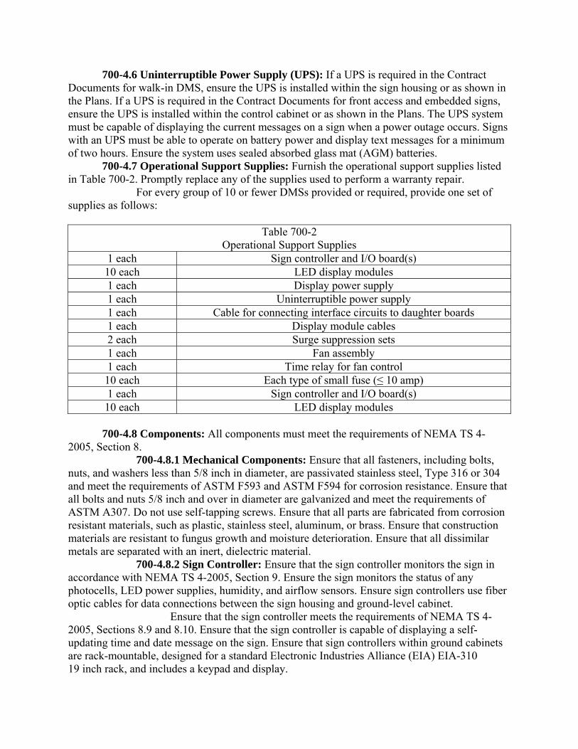
700-4.6 Uninterruptible Power Supply (UPS): If a UPS is required in the Contract Documents for walk-in DMS, ensure the UPS is installed within the sign housing or as shown in the Plans. If a UPS is required in the Contract Documents for front access and embedded signs, ensure the UPS is installed within the control cabinet or as shown in the Plans. The UPS system must be capable of displaying the current messages on a sign when a power outage occurs. Signs with an UPS must be able to operate on battery power and display text messages for a minimum of two hours. Ensure the system uses sealed absorbed glass mat (AGM) batteries. 700-4.7 Operational Support Supplies: Furnish the operational support supplies listed in Table 700-2. Promptly replace any of the supplies used to perform a warranty repair. For every group of 10 or fewer DMSs provided or required, provide one set of supplies as follows:
Table 700-2 Operational Support Supplies
1 each Sign controller and I/O board(s) 10 each LED display modules 1 each Display power supply 1 each Uninterruptible power supply 1 each Cable for connecting interface circuits to daughter boards 1 each Display module cables 2 each Surge suppression sets 1 each Fan assembly 1 each Time relay for fan control 10 each Each type of small fuse (≤ 10 amp) 1 each Sign controller and I/O board(s) 10 each LED display modules
700-4.8 Components: All components must meet the requirements of NEMA TS 4-2005, Section 8. 700-4.8.1 Mechanical Components: Ensure that all fasteners, including bolts, nuts, and washers less than 5/8 inch in diameter, are passivated stainless steel, Type 316 or 304 and meet the requirements of ASTM F593 and ASTM F594 for corrosion resistance. Ensure that all bolts and nuts 5/8 inch and over in diameter are galvanized and meet the requirements of ASTM A307. Do not use self-tapping screws. Ensure that all parts are fabricated from corrosion resistant materials, such as plastic, stainless steel, aluminum, or brass. Ensure that construction materials are resistant to fungus growth and moisture deterioration. Ensure that all dissimilar metals are separated with an inert, dielectric material. 700-4.8.2 Sign Controller: Ensure that the sign controller monitors the sign in accordance with NEMA TS 4-2005, Section 9. Ensure the sign monitors the status of any photocells, LED power supplies, humidity, and airflow sensors. Ensure sign controllers use fiber optic cables for data connections between the sign housing and ground-level cabinet. Ensure that the sign controller meets the requirements of NEMA TS 4-2005, Sections 8.9 and 8.10. Ensure that the sign controller is capable of displaying a self-updating time and date message on the sign. Ensure that sign controllers within ground cabinets are rack-mountable, designed for a standard Electronic Industries Alliance (EIA) EIA-310 19 inch rack, and includes a keypad and display.
700-4.8.3 Display System Hardware: Ensure the sign utilizes a system data interface circuit for communications between the sign controller and display modules. Except for embedded DMS, ensure that the following components reside inside the sign housing: sign controller (master or slave), display system interface circuits, display modules, power supplies, local and remote control switches, LED indicators, EIA-232 null modem cables (minimum of four feet long for connecting laptop computer to sign controller), and surge protective devices. 700-4.8.4 Control Cabinet: Provide a control cabinet that meets the requirements of Section 676. Ensure that the minimum height of the cabinet is 46 inches. Provide a ground control cabinet that includes the following assemblies and components: power indicator, surge suppression on both sides of all electronics, communication interface devices, connection for a laptop computer for local control and programming, a four foot long cable to connect laptop computers, a workspace for a laptop computer, and duplex outlets. Provide for all telephone, data, control, power, and confirmation connections between the sign and ground control box, and for any required wiring harnesses and connectors. 700-4.8.5 Sign Controller Communication Interfaces: Ensure the sign controller has communication interfaces in accordance with NEMA TS 4-2005, Section 8.7.1. Ensure that EIA-232 serial interfaces support the following:
Table 700-3 Communication Interface Requirements
Data Bits 7 or 8 bits Parity Even, Odd, or None
Number Stop Bits 1 or 2 bit Ensure the sign controller has a 10/100 Base TX 8P8C port or a 100 Base FX port Ethernet interface. For dial-up operations, acquire and bear the charges of installing and connecting the dial-up telephone line. Provide modems to be retained by the Department at each location. Provide a user-selectable data transmission rate of up to 19.2 kbps for dial-up operations. Ensure that switching between dial-up, Ethernet, and multidrop operation does not require sign controller software or hardware modifications. Ensure that the TMC or a laptop computer can be used to remotely reset the sign controller. 700-4.9 Message and Status Monitoring: Ensure the DMS provides two modes of operation: (1) remote operation, where the TMC commands and controls the sign and determines the appropriate message or test pattern; and (2) local operation, where the sign controller or a laptop computer commands and controls the sign and determines the appropriate message or test pattern. Ensure that the sign can perform the following functions: 1. Control Selection – Ensure that local or remote sign control can be selected. Ensure that there is a visual indicator on the controller that identifies whether the sign is under local or remote control.
2. Message Selection – Ensure that the sign controller can select a blank message or any one of the messages stored in the sign controller’s nonvolatile memory when the control mode is set to local. 3. Message Implementation – Ensure that the sign controller can activate the selected message. Ensure that the sign can be programmed to display a user-defined message, including a blank page, in the event of power loss. Ensure that message additions, deletions, and sign controller changes may be made from either the remote TMC or a local laptop computer. Ensure that each font may be customized, and modifications to a font may be downloaded to the sign controller from the TMC or a laptop computer at any time without any software or hardware modifications. Ensure that there is no perceivable flicker or ghosting of the pixels during sign erasure and writing periods. 700-4.10 TMC Communication Specification for all DMS: Ensure that the sign controller is addressable by the TMC through the Ethernet communications network using software that complies with the NTCIP 1101 base standard (formerly the NEMA TS 3.2-1996 Standard), including all amendments as published at the time of Contract letting, the NTCIP Simple Transportation Management Framework, and conforms to Compliance Level 1. Ensure that the software implements all mandatory objects in the supplemental requirement SR-700-4.1.1, Dynamic Message Sign NTCIP Requirements, as published on the Department’s State Traffic Engineering and Operations Office web site at the time of Contract letting. Ensure that the sign complies with the NTCIP 1102v01.15, 2101v01.19, 2103v02.07, 2201v01.15, 2202v01.05, and 2301v02.19 Standards. Ensure that the sign complies with NTCIP 1103v02.17, Section 3. Ensure that the controller’s internal time clock can be configured to synchronize to a time server using the network time protocol (NTP). NTP synchronization frequency must be user-configurable and permit polling intervals from once per minute to once per week in one-minute increments. The controller must allow the user to define the NTP server by internet protocol (IP) address. Provide communications line circuits that are point-to-point or multipoint, and that provide full duplex asynchronous data transmissions at the rate shown in the Contract Documents or directed by the Engineer. Assign each sign controller a unique address. 700-4.11 Sign Control Software: Ensure that the sign is provided with computer software from its manufacturer that allows an operator to program, operate, exercise, diagnose, and read current status of all sign features and functions using a laptop computer. Ensure that sign control software provides a graphical representation that visibly depicts the sign face and the current ON/OFF state of all pixels as well as allows messages to be created and displayed on the sign. Ensure that the laptop computer and sign can communicate when connected directly by an EIA-232 cable and via Ethernet. Ensure that the software allows communication between multiple users and multiple signs across the same communication network. 700-4.12 Sign Support Structure: Meet the requirements of 700-2.2. 700-4.13 Installation Requirements: Provide a walk-in DMS for locations over interstate travel lanes. Do not install the sign prior to the availability of electric power. Verify that any ventilation system incorporated within the sign is operational within 72 hours after sign installation.
Ensure that the location of the lifting eyebolts, left in place or removed, is sealed to prevent water entry after installation. Load the initial message libraries on both the sign control software and the sign controller. The Engineer will furnish the messages to be placed in these libraries. 700-4.14 Documentation: Provide documentation for electronic equipment in accordance with 603-8. 700-4.15 Licensing: Ensure that the manufacturer grants the Department a license that allows the Department to use and internally distribute any and all sign communications protocols, operating systems, drivers, and documentation. 700-4.16 Technical Assistance: Ensure that a manufacturer’s representative is available to assist the Contractor’s technical personnel during pre-installation testing and installation. Do not provide initial power to the signs without the permission of the manufacturer’s representative. 700-4.17 Environmental Requirements: The DMS must meet the requirements of NEMA TS 4-2005, Section 2. 700-4.18 Pre-installation Field Testing: Conduct pre-installation tests on all units at a Contractor-provided facility within the appropriate District. Perform the tests on each unit supplied to verify that no damage was done to any sign during the shipment and delivery process. Notify the Engineer a minimum of 10 calendar days before the start of any tests. Conduct all tests according to the approved test procedures detailed in this Section. Each DMS must pass the individual tests detailed below prior to installation. 700-4.18.1 Material Inspection: Examine each DMS carefully to verify that the materials, design, construction, markings, and workmanship comply with all applicable standards, specifications, and requirements. 700-4.18.2 Operational Test: Operate each DMS long enough to permit equipment temperature stabilization, and to check and record an adequate number of performance characteristics to ensure compliance with applicable standards, specifications, and requirements. 700-4.18.3 Pre-Installation Test Failure Consequence: If any unit fails, the unit shall be corrected or another unit substituted in its place and the test repeated. If a unit has been modified as a result of a failure, a report shall be prepared and delivered to the Engineer. The report shall describe the nature of the failure and the corrective action taken. If a failure pattern develops, the Engineer may direct that design and construction modifications be made to all units without additional cost to the Department or an extension of the Contract Time. 700-4.19 Installed Site Tests: Conduct an approved, stand-alone equipment installation test at the field site. Test all stand-alone (i.e., non-network) functions of the field equipment using equipment installed as detailed in the Plans and as approved by the Engineer. Complete approved data forms and turn them over to the Engineer for review and as a basis for rejection or acceptance. Provide a minimum notice of 30 calendar days prior to all tests to permit the Engineer or his representative to observe each test. If any unit fails to pass its stand-alone test, correct the unit or substitute another unit in its place, then repeat the test. If a unit has been modified as a result of a stand-alone test failure, prepare a report describing the nature of the failure and the corrective action taken and deliver it to the Engineer
prior to re-testing the unit. If a failure pattern develops, the Engineer may direct that design and construction modifications be made to all units without additional cost to the Department or an extension of the Contract Time. 700-4.20 System Testing: Conduct approved DMS system tests on the field equipment with the master equipment including, at a minimum, all remote control functions. Display the return status codes from the sign controller for a minimum of 72 hours. Complete approved data forms and turn them over to the Engineer for review, and as a basis for rejection or acceptance. Demonstrate the sign’s ability to display the proper predefined message or remain blank when power is restored following an AC power interruption. If the system test fails because of any subsystem component, repair that component or substitute another in its place, then repeat the test. If a component has been modified as a result of a system test failure, prepare a report and deliver it to the Engineer prior to retesting. 700-4.21 Operational Testing: After the system testing is successfully completed; conduct one continuous 72 hour, full-operating test prior to conducting the 30 day acceptance test. The Engineer will approve the type of tests to be conducted. Include in the tests all control, monitoring, and communications functions of the field equipment by the master equipment. 700-4.22 Acceptance Testing: Conduct a 30 day acceptance test after the successful completion of the approved 72 hour operational test. During the 30 day test period, limit downtime due to mechanical, electrical, or other malfunctions to a maximum total of five calendar days. If the equipment fails to operate for a total of five or more calendar days, testing will be restarted. The Engineer may select to pause and extend the 30 day test period by the number of days lost by failure and repair time in lieu of restarting the full 30 day test. The Engineer will furnish the Contractor with a letter of approval and completion stating the first and last day of the 30 day test period. 700-4.23 Warranty: Ensure that the DMS system and equipment has a manufacturer’s warranty covering defects for a minimum of five years from the date of final acceptance by the Engineer in accordance with 5-11 and Section 608. 700-4.24 Method of Measurement: For each DMS, the quantity to be paid will be each sign furnished, installed, complete in accordance with the details shown in the Plans, warranted, made fully operational, and tested in accordance with the specifications in this Section. For each DMS Support Structure, the quantity to be paid will be each structure furnished, installed, complete in accordance with the details shown in the Plans; including posts and supports, catwalks, handrails, footings, excavation, site grounding, painting, and incidentals necessary to complete the work. 700-4.25 Basis of Payment: Price and payment will be full compensation for furnishing all materials and completing all work as specified in this Section or as shown in the Plans. Payment will be made under:
700-5 Electronic Display Sign. 700-5.1 Description: All Electronic Display Signs (EDS) must meet the physical display and operational requirements for warning or regulatory signs described in the MUTCD and the SHS.
EDS are specialized electronic signs that include dynamic display components. The term EDS refers to a general category of electronically enhanced signs that includes electronic warning signs (EWS), electronic regulatory signs (ERS), electronic speed feedback signs (ESFS), and blank-out signs (BOS). 700-5.2 Material: EWS, ERS, and ESFS must allow attachment to vertical and horizontal support structures as part of a single or double sign post configuration. Bolts must be used for load bearing attachments. 700-5.2.1 Requirements Common to all EDS: All EDS must be designed to withstand the loads defined in the Department’s Structures Manual without deformation or damage. EDS, other than BOS, must provide an option to include flashing beacons. Printed circuit boards shall be protected with conformal coating. Housings that contain electronics shall be constructed of aluminum alloy sheet a minimum of .090 inches thick. Welding used during the construction of EDS must be accordance with Section 965. 700-5.2.1.1 General: EDS, other than BOS, shall include a static sign panel with an integrated dynamic display. Signs included on the APL will be designated with a size and type category and may be listed with restrictions, such as “requires District Traffic Operations Engineer approval”, “school zones only”, or “low speed only”. 700-5.2.1.2 Electronic Display Sign with Static Sign Panel: EDS that include both a static sign and dynamic display may be a modular system comprised of a static sign with an attached electronic display. Static sign panels shall meet the Department’s requirements for highway signing found in this Section. 700-5.2.2 Electronic Display: Electronic displays shall appear completely blank (dark) when not energized. No phantom characters or graphics will be allowed under any ambient light conditions. 700-5.2.2.1 Housing: The housing must protect and seal the dynamic display and other internal electronics. Any polycarbonate material used on the sign face must be a minimum 90% UV opaque and resistant to fading and yellowing. The housing shall be NEMA 3R rated and prevent unauthorized access. The housing shall include weather tight cable entry or connection points for any required power or data connections. 700-5.2.2.2 Cabinet: Any equipment cabinets provided with the EDS must be listed on the APL. 700-5.2.2.3 Optical, Electrical, and Mechanical Specifications for Display Modules: Ensure that all LEDs operate within the LED manufacturer’s recommendations for typical forward voltage, peak pulsed forward current, and other ratings. Component ratings shall not be exceeded under any operating conditions. 700-5.2.2.4 LED and Pixel Specifications: Ensure that all LEDs used in the display have a wavelength output that varies no more than plus or minus two nanometers from the specified peak wavelength. Ensure that the display and LED pixel cone of vision is a minimum of 15 degrees (centered around the optical axis, or zero point, of the pixel). The cone perimeter is defined by the point where light output intensity is 50% of the intensity measured at the zero point of the pixel. For all colors other than white, ensure that the sign display produces an overall luminous intensity of at least 9200 candelas per square meter when operating at 100% intensity. For white or full color matrix displays ensure that the sign display produces white with an overall luminous intensity of at least 12,400 candelas per square meter when operating at 100% intensity. Provide documentation that indicates the LED brightness and color bins that are used in each pixel. Ensure that LEDs are individually mounted on a PCB, and are able to be
removed and replaced using conventional electronic repair methods. Encapsulated LEDs within a pixel are not allowed. ERS LEDs must be arranged and powered in a manner that maintains a discernible message in the event of a single LED or pixel failure. 700-5.2.2.5 Character Size, Fonts, and Graphics: The minimum numeral and letter size of the electronic display must meet or exceed the numeral and letter sizes prescribed in the MUTCD and the SHS. Fonts and graphics must mimic the characteristics of fonts and graphics defined in the MUTCD and SHS. 700-5.2.3 Electronic Display Controller: Any electronic display controller required for the operation of the EDS shall be housed within the sign and be equipped with a security lockout feature to prevent unauthorized use. The controller shall have the capability to provide a stipulated default message upon loss of controller function. A blank message is acceptable. 700-5.2.3.1 Communication: The electronic display controller shall possess a minimum of one serial interface with the ability to connect to a laptop computer. The serial data interface shall support multiple data rates from 9600 bps to 115200 bps. 700-5.2.3.2 Configuration and Management: Ensure that the sign is provided with computer software from its manufacturer that allows a user to program, operate, exercise, diagnose, and read current status of all sign features and functions using a laptop. 700-5.2.4 Operation and Performance: Ensure that the EDS is visible from a distance of at least 1/4 mile and legible from a distance of 400 feet for applications on roads with a speed limit less than 45 mph and visible from a distance of at least 1/2 mile and legible from a distance of at least 650 feet for roads with speed limits 45 mph or higher. In both cases, the requirements must be met under both day and night conditions. The electronic display shall automatically adjust brightness for day and night operation. The EDS must be equipped with a light sensor that accurately measures ambient light level conditions at the sign location. The EDS must automatically adjust LED intensity based on the ambient light conditions in small enough increments that the sign’s brightness changes smoothly, with no perceivable brightness change between adjacent levels. Stray headlights shining on the photoelectric sensor at night must not cause LED brightness changes. Flashing messages must not exceed 150 flashes per minute. 700-5.2.5 Mechanical Specifications: EDS mounting provisions and mounting hardware must accommodate sign weight and wind loading requirements of the Department’s Structures Manual. BOS must be designed to accommodate overhead attachment using a tri-stud signal hanger. Multiple tri-stud attachment points may be used to meet weight and wind loading requirements. Tri-stud attachment points must be weather-tight and structurally reinforced. 700-5.2.5.1 Fasteners and Attachment Hardware: Ensure that all assembly hardware, including nuts, bolts, external screws and locking washers less than 5/8 inch in diameter, are Type 304 or 316 passivated stainless steel. Stainless steel bolts, screws and studs must meet ASTM F593. Nuts must meet ASTM F594. All assembly hardware greater than or equal to 5/8 inch in diameter must be galvanized. Bolts, studs, and threaded rod must meet ASTM A307. Structural bolts must meet ASTM A325. 700-5.2.6 Electrical Specifications: All power inputs must be fuse and reverse polarity protected. All EDS must be able to recover from power loss and return to their operational state without user intervention. 700-5.2.6.1 Solar Power: Solar powered signs must be capable of fully autonomous operation 24 hours per day, 365 days per year. Batteries must be a standard 12 volt
deep cycle battery suitable for the application and operating environment. Flooded lead-acid batteries are prohibited. Batteries must be capable of providing 10 days of continuous operation without sunlight. Charging system must use a solar charge controller with temperature compensation. The system must provide for automatic battery charging, overcharge protection, and have indications that display current status and faults. 700-5.2.6.2 AC Power: Fluctuations in line voltage must have no visible effect on the appearance of the display. 700-5.2.7 Electronic Warning Signs (EWS): The EWS must be designed to alert road users to conditions that might call for a reduction of speed or an action, in the interest of safety and efficient traffic operations. EWS must include a secure wireless connection to communicate with a nearby laptop. 700-5.2.7.1 EWS Foreground/Background Colors: If a black background is used on the changeable electronic display, the color used for the legend must match the background color that would be used on a standard sign for that type of legend, in accordance with the MUTCD. Black EWS display backgrounds must be flat black (FED-STD-595-37038) with a reflectance value not exceeding 25%. EWS must utilize yellow LEDs with a peak wavelength of either 585 or 590 nanometers. EWS must have a minimum one inch contrasting margin around illuminated characters or graphics. 700-5.2.7.2 Speed Detector: EWS that detect or display the speed of approaching vehicles must be programmable for the posted speed limit and the maximum speed to display. When the detected speed exceeds the maximum programmed speed (high speed cut-off) threshold, the display must automatically blank. Alternately, the display may show an alert message such as “SLOW DOWN” when speeds above the maximum programmed speed threshold are detected. The EWS must detect when the posted speed is exceeded by one mph and then activate the alert. When the alert is activated, the display shall be able to flash. When no advancing traffic is detected, the display must be blank. The speed detector must not activate alerts for vehicles outside the display cone of vision. The speed detector must meet the requirements of FCC Title 47, Part 90 and not require an FCC operating license. The speed detector must operate on 10.8 to 16.6 VDC and draw less than three amperes. The EWS must monitor and display the speed of approaching traffic only. The EWS detector must be able to accurately detect and determine the speed of approaching vehicles. The EWS must be capable of measuring and displaying speeds of approaching traffic only between 10 and 99 mph with an accuracy of plus or minus one mph, 1,000 feet in advance of the sign. 700-5.2.8 Electronic Regulatory Signs: The ERS must be designed to give notice of traffic laws or regulations, such as the posted speed limit. ERS used for variable speed limit (VSL) applications must be able to display speed limits from 5-70 mph in five mph increments and mimic the physical appearance of a static regulatory speed limit sign as shown in the MUTCD and SHS. ERS for VSL applications shall use black characters on a white background. ERS for VSL applications must log the time and date of any speed limit change to internal non-volatile memory. The log must be able to record a minimum of 1,000 events in a first-in, first-out fashion. 700-5.2.8.1 Foreground/Background Colors and Display Types: Display modules for all ERS must have a minimum two inch contrasting margin around digits,
text, or graphics. Type 1 ERS must utilize LED technology for the dynamic display. Type 2 ERS must utilize scrolling-film technology for the dynamic display. 700-5.2.8.2 LED and Pixel Specifications for Type 1 ERS: Type 1 ERS must meet the LED and pixel specifications defined in 700-5.2.2.4. 700-5.2.8.3 Scrolling Film Mechanism for Type 2 ERS: The dynamic display for Type 2 ERS must utilize a scrolling film module comprised of a transparent film with black characters meeting the size and shape requirements shown in the MUTCD and SHS. The transparent film and characters must move in front of a background panel covered with reflective sheeting identical to that used on the static sign panel. The transparent film must be constructed of material that will not yellow, fade, deform, or otherwise deteriorate over the lifetime of the sign. 700-5.2.8.4 ERS Character Size and Font: Fonts and graphics for Type 1 ERS must mimic the characteristics of fonts and graphics defined in the MUTCD and SHS. Fonts and graphics for Type 2 ERS must exactly match the characteristics of fonts and graphics defined in the MUTCD and SHS. 700-5.2.8.5 Variable Speed Limit (VSL) ERS Controller Communications: ERS for variable speed applications must be equipped with a sign controller that includes a minimum of one Ethernet 10/100 Base TX 8P8C port. 700-5.2.8.6 Configuration and Management Requirements for VSL ERS: Ensure that ERS for VSL applications can be managed remotely from a TMC or managed locally using a laptop computer. Ensure that the TMC or a laptop computer can be used to remotely reset VSL sign controllers. Ensure that ERS for VSL applications log and report status, errors, and failures, including data transmission errors, receipt of invalid data, communication failure recoveries, alternating current power failures, power recoveries, display errors, fan and airflow status, temperature status, power supply status, and information on the operational status of the temperature, photocell, airflow, humidity, and LED power supply sensors. Ensure that the sign controller is addressable through an Ethernet communication network using software that complies with the NTCIP requirements published online by the Department’s Transportation Traffic Engineering Research Laboratory (TERL) at: http://www.dot.state.fl.us/trafficoperations/ . Ensure that the sign implements any NTCIP standards required to achieve interoperability and interchangeability. Ensure that any additional objects implemented by the software do not interfere with the standard operation of any mandatory objects. ERS must be compatible with the Department’s SunGuide® software. 700-5.2.8.7 ERS Battery Backup System: AC powered signs must include a battery backup system that maintains full operation of the sign for a minimum of two hours in the event of utility power loss. Operation on battery backup can have no visible effect on the appearance of the display. 700-5.2.9 Blank-Out Signs: EDSs designed for BOS applications must have a black exterior finish (FED-STD-595-37038) with a reflectance value not exceeding 25%. Overhead BOS must include a visor. 700-5.2.10 Electronic Speed Feedback Signs (ESFS): The ESFS must be designed to alert road users of their speed as they approach the sign. 700-5.2.10.1 ESFS Background/Foreground Colors: The ESFS display background must be flat black (FED-STD-595-37038) with a reflectance value not exceeding 25%. ESFS must utilize amber LEDs with a peak wavelength of 590 nanometers. ESFS shall have a minimum one inch contrasting margin around illuminated characters or graphics.
700-5.2.10.2 Speed Detector: The ESFS must be programmable for the posted speed limit and the maximum speed to display. When the detected speed exceeds the maximum programmed speed (high speed cut-off) threshold, the display must automatically blank. Alternately, the display may show an alert message such as “SLOW DOWN” when speeds above the maximum programmed speed threshold are detected. The ESFS must detect when the posted speed is exceeded by one mph and then activate the alert. When the alert is activated, the display must flash at a rate of 50 to 60 cycles per minute. When no advancing traffic is detected, the display must be blank. The speed detector must not activate alerts or display speeds for vehicles outside the display’s cone of vision. The ESFS must meet the requirements of FCC Part 90 and not require an FCC operating license. The speed detector must operate on 10.8 to 16.6 VDC. The ESFS must be capable of measuring speeds of approaching traffic between 10 and 99 mph with an accuracy of plus or minus one mph, 1,000 feet in advance of the sign. 700-5.2.11 Environmental Requirements: The EDS assembly must operate properly during and after being subjected to the environmental testing procedures described in NEMA TS 2, Sections 2.2.7, 2.2.8, and 2.2.9. Fog, frost, or condensation must not form within the dynamic portion of the sign. Electronics must meet FCC Title 47, Subpart B Section 15. 700-5.2.12 Warranty: Ensure that the EDS systems and equipment furnished have a manufacturer’s warranty covering defects in assembly, fabrication, and materials for a minimum of three years. 700-5.3 Installation: For EDS installed within the clear zone, meet the crash testing requirements of NCHRP 350 or MASH 2009. 700-5.4 Method of Measurement: The Contract unit price per assembly for electronic display sign, furnished and installed, will include the static sign panels, electronic display, support structure, foundation, housing, cabinet, controller, speed detector, hardware, electrical connection, and labor necessary for a complete and accepted installation. When the electronic display sign is ground mounted, the Contract price will include the support structure and foundation. All other mounting will include the hardware necessary to complete the attachment to the support structure; the span wire, monotube, or mast arm structure will be paid separately. When a solar panel is specified in the Contract Documents, the Contract unit price will include the solar panel and batteries. 700-5.5 Basis of Payment: Price and payment will be full compensation for all work specified in this Section. Payment will be made under:
Item No. 700- 11- Electronic Display Sign, per assembly.
700-6 Sign Beacon. 700-6.1 Description: Furnish and install flashing beacon assemblies as shown in the Plans. 700-6.2 Materials: Use flashing beacon assemblies and components listed on the APL. Ensure equipment is permanently marked with manufacturer name or trademark, part number, date of manufacture, or serial number. Flashing beacon assemblies incorporating a circular traffic signal must meet the design and functional requirements set forth in MUTCD Chapter 4L. All circular beacons must have a minimum nominal diameter of 12 inches and meet the requirements of Section 650. All beacons must use a LED light source. Beacons designed for use with school zone signing must include a means of calendar scheduling to program days and times of operation.
700-6.2.1 Vehicle Activated Beacon: Vehicle activated beacons must utilize a vehicle detection system listed on the APL. 700-6.2.2 Pedestrian Activated Beacon: Pedestrian activated beacons must utilize a pedestrian detector listed on the APL. 700-6.2.3 Cabinets, Housings, and Hardware: Flashing beacon cabinets must be currently listed on the APL or meet the applicable criteria of Section 676. All housings, other than pole-mounted cabinets, must be powder coated dull black (FED-STD-595-37038) with a reflectance value not exceeding 25% as measured by ASTM E1347. Cabinets and housings must prevent unauthorized access. Flashing beacon assemblies must allow installation on 4-1/2 inch outer diameter posts. Ensure all exposed assembly hardware including nuts, bolts, screws, and locking washers less than 5/8 inch in diameter, is Type 304 or 316 passivated stainless steel and meets the requirements of ASTM F593 and ASTM F594. All assembly hardware greater than or equal to 5/8 inch in diameter must be galvanized and meet the requirements of ASTM A307. 700-6.2.4 Electrical Specifications: Provide equipment that operates on solar power or a nominal voltage of 120 VAC. If the device requires operating voltages of less than 120 VAC, supply the appropriate voltage converter. Solar powered beacon systems must be designed to provide 10 days of continuous operation without sunlight and must automatically charge batteries and prevent overcharging and over-discharging. Solar powered systems must include a charge indicator and AC/DC battery charger. 700-6.2.5 Environmental Specifications: All electronic assemblies must operate as specified during and after being subjected to the transients, temperature, voltage, humidity, vibration, and shock tests described in NEMA TS 2, 2.2.7, 2.2.8, and 2.2.9. All electronic equipment must comply with FCC Title 47 Subpart B Section 15. 700-6.3 Installation: Install equipment according to the manufacturer’s instructions. Flashing beacons installations must meet MUTCD Chapter 4L. Install beacons used for school signs in accordance with Design Standards. For EDS within the clear zone, meet the crash testing requirements of NCHRP 350 or MASH 2009. 700-6.4 Warranty: Ensure all flashing beacons have a manufacturer’s warranty covering defects for a minimum of five years from the date of final acceptance in accordance with 5-11 and Section 608. Ensure the manufacturer will furnish replacements for any part or equipment found to be defective during the warranty period at no cost to the Department or maintaining agency within 30 calendar days of notification. 700-6.5 Method of Measurement: The Contract unit price for sign beacon, furnished and installed, will consist of the flashing beacons, cabinet, housing, controller, hardware, and labor necessary for a complete and accepted installation. Signal cable from the cabinet to the signs will be paid separately under the applicable item for signal cable. When solar power is specified in the Contract Documents, the Contract unit price will include the solar panel, batteries, and electronics. 700-6.6 Basis of Payment: Price and payment will be full compensation for all work specified in this Section. Payment will be made under: