Assignment No: 1 Purpose: Understanding the implementation details of relationships among classes Lab pre work: Prepare a class diagram from the given problem description using UML2.0 notations. Laboratory work: mplement the class diagram with a suitable ob!ect oriented language. Theory: Class Diagrams Class diagrams are visual representations of the static structure and composition of a particular system using the conventions set by the Unified Modeling Language (UML). Out of all the UML diagram typesit is one of the most used ones. System designers use class diagrams as a way of simplifying how obects in a system interact with each other. Using class diagrams! it is easier to describe all the classes! pac"ages! and interfaces that constitute a system and how these components are interrelated. #or e$ample! a simple class diagram may be used to show how an organi%ation such as a convenient store chain is set up. On the other hand! precisely detailed class diagrams can readily be used as the primary reference for translating the designed system into a programming code. &he following figure is an e$ample of a simple class diagram' Simple class diagram with attributes and operations n the e$ample! a class called loan account* is depicted. Classes in class diagrams are represented by bo$es that are partitioned into three'
Purpose: Understanding the implementation details of relationshipsamong classesLab pre work: Prepare a class diagram from the given problem description usingUML2.0notations.
Laboratory work: mplement the class diagram with a suitable ob!ect orientedlanguage.
Theory:
Class Diagrams
Class diagrams are visual representations of the static structure and composition of a particular
system using the conventions set by the Unified Modeling Language (UML). Out of all the UML
diagram types it is one of the most used ones. System designers use class diagrams as a way of
simplifying how obects in a system interact with each other. Using class diagrams! it is easier to
describe all the classes! pac"ages! and interfaces that constitute a system and how these
components are interrelated. #or e$ample! a simple class diagram may be used to show how an
organi%ation such as a convenient store chain is set up. On the other hand! precisely detailed
class diagrams can readily be used as the primary reference for translating the designed system
into a programming code.
&he following figure is an e$ample of a simple class diagram'
Simple class diagram with attributes and operations
n the e$ample! a class called loan account* is depicted. Classes in class diagrams are
represented by bo$es that are partitioned into three'
". #he top partition contains the name of the class.
2. #he middle part contains the class$s attributes.
%. #he bottom partition shows the possible operations that are associated withthe class.
&hose should be pretty easy to see in the e$ample' the class being described is a loan account!
some of whose attributes include the type of loan! the name of the borrower+loaner! the specificdate the loan was released and the loan amount. ,s in the real world! various transactions or
operations may be implemented on e$isting loans such as renew and e$tend. &he e$ample shows
how class diagrams can encapsulate all the relevant data in a particular scenario in a very
systematic and clear way.
n obect-oriented modeling! class diagrams are considered the "ey building bloc"s that enable
information architects! designers! and developers to show a given systems classes! their
attributes! the functions or operations that are associated with them! and the relationships among
the different classes that ma"e up a system.
Relationships in Class Diagrams
Classes are interrelated to each other in specific ways. n particular! relationships in class
diagrams include different types of logical connections. &he following are such types of logical
is very similar to the aggregation relationship! with the only difference being its "ey purpose of
emphasi%ing the dependence of the contained class to the life cycle of the container class. &hat
is! the contained class will be obliterated when the container class is destroyed. #or e$ample! a
shoulder bags side poc"et will also cease to e$ist once the shoulder bag is destroyed. &o depict a
composition relationship in a UML diagram! use a directional line connecting the two classes!
with a filled diamond shape adacent to the container class and the directional arrow to the
contained class.
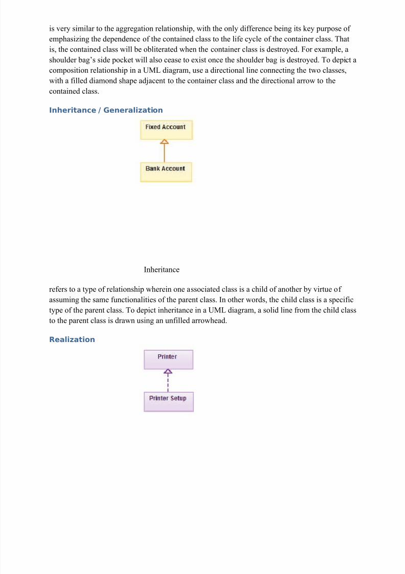
nheritance ! "enerali#ation
nheritance
refers to a type of relationship wherein one associated class is a child of another by virtue of
assuming the same functionalities of the parent class. n other words! the child class is a specifictype of the parent class. &o depict inheritance in a UML diagram! a solid line from the child class
to the parent class is drawn using an unfilled arrowhead.
Purpose: mplementation of a design modelLab pre work: Prepare a design model from analysis model in the form of UML 2class diagram.
Laboratory work: mplement the design model with a suitable ob!ect orientedlanguage
Overview:
&he class diagram is a static diagram. t represents the static view of an application. Classdiagram is not only used for visuali%ing! describing and documenting different aspects of a
system but also for constructing e$ecutable code of the software application.
&he class diagram describes the attributes and operations of a class and also the constraints
imposed on the system. &he class diagrams are widely used in the modelling of obect orientedsystems because they are the only UML diagrams which can be mapped directly with obect
oriented languages.
&he class diagram shows a collection of classes! interfaces! associations! collaborations andconstraints. t is also "nown as a structural diagram.
Purpose:
&he purpose of the class diagram is to model the static view of an application. &he class
diagrams are the only diagrams which can be directly mapped with obect oriented languages andthus widely used at the time of construction.
&he UML diagrams li"e activity diagram! se3uence diagram can only give the se3uence flow of
the application but class diagram is a bit different. So it is the most popular UML diagram in the
coder community.
So the purpose of the class diagram can be summari%ed as'
• ,nalysis and design of the static view of an application.
Class diagrams are the most popular UML diagrams used for construction of software
applications. So it is very important to learn the drawing procedure of class diagram.
Class diagrams have lot of properties to consider while drawing but here the diagram will beconsidered from a top level view.
Class diagram is basically a graphical representation of the static view of the system andrepresents different aspects of the application. So a collection of class diagrams represent the
whole system.
&he following points should be remembered while drawing a class diagram'
• &he name of the class diagram should be meaningful to describe the aspect of the system.
• 5ach element and their relationships should be identified in advance.
• 0esponsibility (attributes and methods) of each class should be clearly identified.
• #or each class minimum number of properties should be specified. 4ecause unnecessary
properties will ma"e the diagram complicated.
• Use notes when ever re3uired to describe some aspect of the diagram. 4ecause at the end
of the drawing it should be understandable to the developer+coder.
• #inally! before ma"ing the final version! the diagram should be drawn on plain paper and
rewor" as many times as possible to ma"e it correct.
6ow the following diagram is an e$ample of an Order System of an application. So it describes a particular aspect of the entire application.
• #irst of all Order and Customer are identified as the two elements of the system and they
have a one to many relationship because a customer can have multiple orders.
• 7e would "eep Order class is an abstract class and it has two concrete classes
(inheritance relationship) SpecialOrder and NormalOrder .
• &he two inherited classes have all the properties as the Order class. n addition they have
additional functions li"e dispatch () and receive ().
So the following class diagram has been drawn considering all the points mentioned above'
Class diagram is a static diagram and it is used to model static view of a system. &he static viewdescribes the vocabulary of the system.
Class diagram is also considered as the foundation for component and deployment diagrams.Class diagrams are not only used to visuali%e the static view of the system but they are also used
to construct the e$ecutable code for forward and reverse engineering of any system.
8enerally UML diagrams are not directly mapped with any obect oriented programming
languages but the class diagram is an e$ception.
Class diagram clearly shows the mapping with obect oriented languages li"e 9ava! C:: etc. So
from practical e$perience class diagram is generally used for construction purpose.
So in a brief! class diagrams are used for'
• /escribing the static view of the system.
• Showing the collaboration among the elements of the static view.
• /escribing the functionalities performed by the system.
• Construction of software applications using obect oriented languages.
Assignment %o:&
Purpose: mplementation of a state model from the given description'Lab pre work: Prepare a state model from the given problem description and draw astatediagram using UML2 notationsLaboratory work: mplement the state model with a suitable ob!ect oriented
language
Overview:
&he name of the diagram itself clarifies the purpose of the diagram and other details. t describes
different states of a component in a system. &he states are specific to a component+obect of asystem.
&he following is an e$ample of a Statechart diagram where the state of Order obect is analy%ed.
&he first state is an idle state from where the process starts. &he ne$t states are arrived for eventsli"e send request ! confirm request ! and dispatch order . &hese events are responsible for state
changes of order obect.
/uring the life cycle of an obect (here order obect) it goes through the following states and
there may be some abnormal e$ists also. &his abnormal e$it may occur due to some problem in
the system. 7hen the entire life cycle is complete it is considered as the complete transaction asmentioned below.
&he initial and final state of an obect is also shown below.
Where to use tate!hart Diagrams?
#rom the above discussion we can define the practical applications of a Statechart diagram.
Statechart diagrams are used to model dynamic aspect of a system li"e other four diagrams
disused in this tutorial. 4ut it has some distinguishing characteristics for modeling dynamic
nature.
Statechart diagram defines the states of a component and these state changes are dynamic in
nature. So its specific purpose is to define state changes triggered by events. 5vents are internal
or e$ternal factors influencing the system.
Statechart diagrams are used to model states and also events operating on the system. 7henimplementing a system it is very important to clarify different states of an obect during its life
time and statechart diagrams are used for this purpose. 7hen these states and events are
identified they are used to model it and these models are used during implementation of thesystem.
f we loo" into the practical implementation of Statechart diagram then it is mainly used to
analy%e the obect states influenced by events. &his analysis is helpful to understand the system behaviour during its e$ecution.
So the main usages can be described as'
• &o model obect states of a system.
• &o model reactive system. 0eactive system consists of reactive obects.
• &o identify events responsible for state changes.
• #orward and reverse engineering.
Assignment %o:(
Purpose: Preparing an interaction model from the given detailsPrepare a use case model/ seuence model and activity model from the givendescription using
&o model a system the most important aspect is to capture the dynamic behaviour. &o clarify a bit
in details! dynamic behaviour means the behaviour of the system when it is running +operating.
So only static behaviour is not sufficient to model a system rather dynamic behaviour is moreimportant than static behaviour. n UML there are five diagrams available to model dynamic
nature and use case diagram is one of them. 6ow as we have to discuss that the use case diagram
is dynamic in nature there should be some internal or e$ternal factors for ma"ing the interaction.
&hese internal and e$ternal agents are "nown as actors. So use case diagrams are consists ofactors! use cases and their relationships. &he diagram is used to model the system+subsystem of
an application. , single use case diagram captures a particular functionality of a system.
So to model the entire system numbers of use case diagrams are used.
Purpose:
&he purpose of use case diagram is to capture the dynamic aspect of a system. 4ut this definition
is too generic to describe the purpose.
4ecause other four diagrams (activity! se3uence! collaboration and Statechart) are also having the
same purpose. So we will loo" into some specific purpose which will distinguish it from otherfour diagrams.
Use case diagrams are used to gather the re3uirements of a system including internal and
e$ternal influences. &hese re3uirements are mostly design re3uirements. So when a system is
analy%ed to gather its functionalities use cases are prepared and actors are identified.
6ow when the initial tas" is complete use case diagrams are modelled to present the outsideview.
So in brief! the purposes of use case diagrams can be as follows'
• Used to gather re3uirements of a system.
• Used to get an outside view of a system.
• dentify e$ternal and internal factors influencing the system.
• Show the interacting among the re3uirements are actors.
Use case diagrams are considered for high level re3uirement analysis of a system. So when the
re3uirements of a system are analy%ed the functionalities are captured in use cases.
So we can say that uses cases are nothing but the system functionalities written in an organi%ed
manner. 6ow the second things which are relevant to the use cases are the actors. ,ctors can be
defined as something that interacts with the system.
&he actors can be human user! some internal applications or may be some e$ternal applications.
So in a brief when we are planning to draw an use case diagram we should have the followingitems identified.
• #unctionalities to be represented as an use case
• ,ctors
• 0elationships among the use cases and actors.
Use case diagrams are drawn to capture the functional re3uirements of a system. So after
identifying the above items we have to follow the following guidelines to draw an efficient usecase diagram.
• &he name of a use case is very important. So the name should be chosen in such a way so
that it can identify the functionalities performed.
• 8ive a suitable name for actors.
• Show relationships and dependencies clearly in the diagram.
• /o not try to include all types of relationships. 4ecause the main purpose of the diagram
is to identify re3uirements.
• Use note when ever re3uired to clarify some important points.
&he following is a sample use case diagram representing the order management system. So if weloo" into the diagram then we will find three use cases (Order! SpecialOrder and 6ormalOrder)
and one actor which is customer.
&he SpecialOrder and NormalOrder use cases are e$tended from Order use case. So they have
e$tends relationship. ,nother important point is to identify the system boundary which is shownin the picture. &he actor Customer lies outside the system as it is an e$ternal user of the system.
,s we have already discussed there are five diagrams in UML to model dynamic view of a
system. 6ow each and every model has some specific purpose to use. ,ctually these specific
purposes are different angles of a running system.
So to understand the dynamics of a system we need to use different types of diagrams. Use case
diagram is one of them and its specific purpose is to gather system re3uirements and actors.
Use case diagrams specify the events of a system and their flows. 4ut use case diagram neverdescribes how they are implemented. Use case diagram can be imagined as a blac" bo$ whereonly the input! output and the function of the blac" bo$ is "nown.
&hese diagrams are used at a very high level of design. &hen this high level design is refined
again and again to get a complete and practical picture of the system. , well structured use case
also describes the pre condition! post condition! e$ceptions. ,nd these e$tra elements are used toma"e test cases when performing the testing.
,lthough the use cases are not a good candidate for forward and reverse engineering but still
they are used in a slight different way to ma"e forward and reverse engineering. ,nd the same is
true for reverse engineering. Still use case diagram is used differently to ma"e it a candidate forreverse engineering.
n forward engineering use case diagrams are used to ma"e test cases and in reverse engineering
use cases are used to prepare the re3uirement details from the e$isting application.
So the following are the places where use case diagrams are used'
#rom the name Interaction it is clear that the diagram is used to describe some type of
interactions among the different elements in the model. So this interaction is a part of dynamic
behaviour of the system.
&his interactive behaviour is represented in UML by two diagrams "nown as Sequence diagram and Collaboration diagram. &he basic purposes of both the diagrams are similar.
Se3uence diagram emphasi%es on time se3uence of messages and collaboration diagram
emphasi%es on the structural organi%ation of the obects that send and receive messages.
Purpose:
&he purposes of interaction diagrams are to visuali%e the interactive behaviour of the system.
6ow visuali%ing interaction is a difficult tas". So the solution is to use different types of models
to capture the different aspects of the interaction.
&hat is why se3uence and collaboration diagrams are used to capture dynamic nature but from adifferent angle.
So the purposes of interaction diagram can be describes as'
• &o capture dynamic behaviour of a system.
• &o describe the message flow in the system.
• &o describe structural organi%ation of the obects.
• &o describe interaction among obects.
How to draw #ntera!tion Diagram?
,s we have already discussed that the purpose of interaction diagrams are to capture the dynamicaspect of a system. So to capture the dynamic aspect we need to understand what a dynamic
aspect is and how it is visuali%ed. /ynamic aspect can be defined as the snap shot of the running
system at a particular moment.
7e have two types of interaction diagrams in UML. One is se3uence diagram and the other is acollaboration diagram. &he se3uence diagram captures the time se3uence of message flow from
one obect to another and the collaboration diagram describes the organi%ation of obects in a
system ta"ing part in the message flow.
So the following things are to identified clearly before drawing the interaction diagram'
• Obects ta"ing part in the interaction.
• Message flows among the obects.
• &he se3uence in which the messages are flowing.
• Obect organi%ation.
#ollowing are two interaction diagrams modeling order management system. &he first diagram is
a se3uence diagram and the second is a collaboration diagram.
$he e%uen!e Diagram:
&he se3uence diagram is having four obects (Customer! Order! SpecialOrder and 6ormalOrder).
&he following diagram has shown the message se3uence for SpecialOrder obect and the same
can be used in case of NormalOrder obect. 6ow it is important to understand the time se3uence
of message flows. &he message flow is nothing but a method call of an obect.
&he first call is sendOrder () which is a method of Order obect. &he ne$t call is confirm () which is a method of SpecialOrder obect and the last call is Dispatch () which is a method of
SpecialOrder obect. So here the diagram is mainly describing the method calls from one obect
to another and this is also the actual scenario when the system is running.
7e have already discussed that interaction diagrams are used to describe dynamic nature of a
system. 6ow we will loo" into the practical scenarios where these diagrams are used. &o
understand the practical application we need to understand the basic nature of se3uence and
collaboration diagram.
&he main purposes of both the diagrams are similar as they are used to capture the dynamic
behaviour of a system. 4ut the specific purposes are more important to clarify and understood.
Se3uence diagrams are used to capture the order of messages flowing from one obect to another.
,nd the collaboration diagrams are used to describe the structural organi%ations of the obectsta"ing part in the interaction. , single diagram is not sufficient to describe the dynamic aspect of
an entire system so a set of diagrams are used to capture is as a whole.
&he interaction diagrams are used when we want to understand the message flow and the
structural organi%ation. 6ow message flow means the se3uence of control flow from one obectto another and structural organi%ation means the visual organi%ation of the elements in a system.
n a brief the following are the usages of interaction diagrams'
• &o model flow of control by time se3uence.
• &o model flow of control by structural organi%ations.
• #or forward engineering.
• #or reverse engineering.
A!tivit& Diagram:
Overview:
,ctivity diagram is another important diagram in UML to describe dynamic aspects of thesystem.
,ctivity diagram is basically a flow chart to represent the flow form one activity to another
activity. &he activity can be described as an operation of the system.
So the control flow is drawn from one operation to another. &his flow can be se3uential! branched or concurrent. ,ctivity diagrams deals with all type of flow control by using different
elements li"e for"! oin etc.
Purpose:
&he basic purposes of activity diagrams are similar to other four diagrams. t captures thedynamic behaviour of the system. Other four diagrams are used to show the message flow from
one obect to another but activity diagram is used to show message flow from one activity to
another.
,ctivity is a particular operation of the system. ,ctivity diagrams are not only used for
visuali%ing dynamic nature of a system but they are also used to construct the e$ecutable system
by using forward and reverse engineering techni3ues. &he only missing thing in activity diagram
is the message part.
t does not show any message flow from one activity to another. ,ctivity diagram is some timeconsidered as the flow chart. ,lthough the diagrams loo"s li"e a flow chart but it is not. t shows
different flow li"e parallel! branched! concurrent and single.
So the purposes can be described as'
• /raw the activity flow of a system.
• /escribe the se3uence from one activity to another.
• /escribe the parallel! branched and concurrent flow of the system.
How to draw A!tivit& Diagram?
,ctivity diagrams are mainly used as a flow chart consists of activities performed by the system.
4ut activity diagram are not e$actly a flow chart as they have some additional capabilities. &heseadditional capabilities include branching! parallel flow! swimlane etc.
4efore drawing an activity diagram we must have a clear understanding about the elements used
in activity diagram. &he main element of an activity diagram is the activity itself. ,n activity is a
function performed by the system. ,fter identifying the activities we need to understand how
they are associated with constraints and conditions.
So before drawing an activity diagram we should identify the following elements'
• ,ctivities
• ,ssociation
• Conditions
• Constraints
Once the above mentioned parameters are identified we need to ma"e a mental layout of the
entire flow. &his mental layout is then transformed into an activity diagram.
&he following is an e$ample of an activity diagram for order management system. n the diagramfour activities are identified which are associated with conditions. One important point should be
clearly understood that an activity diagram cannot be e$actly matched with the code. &he activity
diagram is made to understand the flow of activities and mainly used by the business users.
&he following diagram is drawn with the four main activities'
,fter receiving the order re3uest condition chec"s are performed to chec" if it is normal or
special order. ,fter the type of order is identified dispatch activity is performed and that ismar"ed as the termination of the process.
Where to use A!tivit& Diagrams?
&he basic usage of activity diagram is similar to other four UML diagrams. &he specific usage is
to model the control flow from one activity to another. &his control flow does not include
messages.
&he activity diagram is suitable for modeling the activity flow of the system. ,n application canhave multiple systems. ,ctivity diagram also captures these systems and describes flow from one
system to another. &his specific usage is not available in other diagrams. &hese systems can bedatabase! e$ternal 3ueues or any other system.
6ow we will loo" into the practical applications of the activity diagram. #rom the above
discussion it is clear that an activity diagram is drawn from a very high level. So it gives high
level view of a system. &his high level view is mainly for business users or any other person whois not a technical person.
&his diagram is used to model the activities which are nothing but business re3uirements. So the
diagram has more impact on business understanding rather implementation details.
#ollowing are the main usages of activity diagram'
• Modeling wor" flow by using activities.
• Modeling business re3uirements.
• ;igh level understanding of the system<s functionalities.
• nvestigate business re3uirements at a later stage.
Assignment %o: +
Purpose: mplement a )trategy design patternMap the participants for the strategy design pattern from a given problemdescription andimplement with a suitable ob!ect oriented language
$heor&:
n Strategy pattern! a class behavior or its algorithm can be changed at run time. &his type of
design pattern comes under behavior pattern.
n Strategy pattern! we create obects which represent various strategies and a conte$t obect
whose behavior varies as per its strategy obect. &he strategy obect changes the e$ecuting
algorithm of the conte$t obect.
mplementation
7e are going to create a Strategy interface defining an action and concrete strategy classes
implementing the Strategy interface. Context is a class which uses a Strategy.
StrategyatternDemo! our demo class! will use Context and strategy obects to demonstrate
change in Conte$t behaviour based on strategy it deploys or uses.
Purpose: Understand the concept of Test driven Developmentmplement a design level class diagram 4given as an input5 with #est 'riven'evelopmentapproach.
What is $est'Driven Development ($DD)?&est-driven development starts with developing test for each one of the features. &he test might
fail as the tests are developed even before the development. /evelopment team then developsand refactors the code to pass the test.
&est-driven development is related to the test-first programming evolved as part of e$treme
/01ective: Understand and implement the Concept of a reusa0lecomponentmplement a reusable component in form of !ar 6le 4or in euivalent form for other77 languages5. Use this component in a separate client implementation byimporting the component as a !ar 6le 4or euivalent form for other 77 language5.
Software component reuse is the software engineering practice of creating new software
applications from e$isting components! rather than designing and building them from scratch.0eusable components can be re3uirements specifications! design documents! source code! user
interfaces! user documentation! or any other items associated with software. ,ll products
resulting from the software development life cycle have the potential for reuse.
Business Case for Software Component Reuse
0eusable components are easier to maintain (over time) and typically have a higher 3uality value(more robust and fewer errors). &he practice of component reuse supports the motivation fordevelopment of speciali%ed 8S applications. &he business case is reduced application
development time! reduced application cost! and improved application 3uality. ,ssuming the
motivation for use and development of speciali%ed 8S application software is one or several ofthe following'
o &o reduce time
o &o reduce effort
o &o save dollars or earn dollars
o &o improve 3uality
&hen! the easiest way to accomplish these goals includes one or both of the following'
o mprove staff effectiveness (produce more with less through applied use of
technology or incentives)
o /ecrease production wor"load (produce less new output by reusing previously
produced materials to meet an e3uivalent or increased demand)
5$amples are provided below.
o 0eplace manual drafting of multiple copies of a map with reprographics
technology or create a reusable electronic map and produce copies by replotting
the data (reuse of previously produced data)
o 0eplace production of 8S application source code for multiple applications (by
potentially multiple staff) by sharing and reusing software components of previously produced applications
Obstacles to Software Reuse
• #re3uent architecture and system changes.
• Organi%ational and cultural issues> reuse re3uires a fairly drastic change.
• Lac" of automation tools to assist with specific reuse mechanisms.
• Organi%ation si%e and amount of application development performed will be proportional
to paybac". Smaller organi%ations will not benefit as much from code reuse.
• &oo large of a proect or effort is often attempted initially.
• 5$perience has shown that it re3uires three to five years to implement a formal reuse
program across a large corporation.
• nitially! the end-to-end software life cycle will be longer.
• Lac" of component inde$ing and searching mechanisms.
• /eveloping a componenti%ation scheme or architecture reflecting which components
need to be built and which components should be ac3uired from other providers in the
industry. f a component is e$pected or will be available soon from an outside source!then a wait versus build decision needs to be made.
Characteristics Needed for Qualification as a Reusable Component
n order for a component (specification! design! code) to be reusable! it needs to have certain3ualities that contribute to its reusability. 0eusability is defined as the e$tent to which a software
component can be used with or without changes in multiple software systems! versions! or
implementations (McClure ?@). , list of those characteristics generally sought after to promotereusability as presented by McClure are as follows'
o 8eneral with build-in adaptability+speciali%ation
o Aortable (across hardware and operating systems)
o Certified+testable
o Maintainable
o 5ncapsulated (details are isolated and hidden from user)
uidelines for Creatin! a Reusable Component
McClure has also provided the software industry with techni3ues for building reusable
components independent of whether or not an obect-oriented language is available. &his ma"es
the techni3ue applicable to 8S applications development in the entire line of 5sri developmentlanguages! to include traditional proprietary languages! such as ,ML or ,venue! as well as the
Open /evelopment 5nvironment languages! such as =isual 4asic! C::! or &cl&". &he techni3ues
for creating components most applicable to reuse! as presented by McClure! are as follows'
B. 8enerali%e
. Standardi%e
D. ,utomate
E. Certify
F. /ocument
"ow to Build Reusable Components
Listed below are several practical guidelines and advice to assist developers in the creation ofnew reusable components'
• Collaborate with multiple software engineers throughout the design and definition
phases.
• nstall a reuse analysis stage into all detailed design wor"! so that the opportunities for
reuse can be effectively assessed.
• 4efore building a new component! always chec" to ma"e sure it does not e$ist. ,lwaysattempt reuse before creating a new component.
• Strive for a clearly defined! single purpose per component.
• /ocument all component interface re3uirements! also "nown as parameter lists or
function signatures! in the design phase. /o not attempt to start at the coding phase and
Gdesign as you go.G 0emember that component reuse re3uires much more up-front planning. More design time and less construction time should be e$pected and planned
• 7ith the inputs! results! or outputs and a description of a component! another software
developer should be able to use that component without ever "nowing what the code doesinside the component. &he component should pass this Gself test.G
• Strive for loosely coupled and highly cohesive components.
• /evelop components with overall future use in mind! not ust a single proect.
• ,lways put e$tra effort into error handling and ma"ing components robust.
• /evelop a certification program and communicate the certification criteria to all
component developers.
• Use consistent design styles.
• mplement and use naming conventions.
• 7hen creating documentation! thin" of e$plaining the component to a developer
unfamiliar with the internal wor"ings or a developer who will truly never loo" at the codeof the component.