33
N99A49G70E68S51 Department of Computer Science & Engineering LAB MANUAL FOR CASE TOOLS LAB IV B.Tech I SEM www.studentsfocus.com
N99A49G70E68S51
Department of Computer Science & Engineering
LAB MANUAL FOR
CASE TOOLS LAB
IV B.Tech I SEM
www.studentsfocus.com
N99A49G70E68S51
OBJECTIVES OF THE LAB 1 .Documenting user requirements using the UML notation
2. Description of the various components of UML
3. The use of Use Cases
AIMS OF UML
1. Models helps us to visualize a system as it is or an as we want it to be. 2. Models permit us to specify the structure or behavior of a system. 3. Models gives us a template guides us in constructing a system. 4. Models document the decisions we have made.
REQUIREMENTS Hardware andSoftware required: 1. A working computer system with either Windows or Linux
2. Rational Rose Software or Visual Paradigm Software
www.studentsfocus.com
N99A49G70E68S51
LAB SYLLABUS PROGRAMS (JNTU)
Students are divided into batches of 5 each and each batch has to draw the following diagrams using UML for an ATM system whose description is given below. UML diagrams to be developed are:
1. Use Case Diagram. 2. Class Diagram. 3. Sequence Diagram. 4. Collaboration Diagram. 5. State Diagram 6. Activity Diagram. 7. Component Diagram 8. Deployment Diagram.
Description for an ATM System
The software to be designed will control a simulated automated teller machine (ATM) having a magnetic stripe reader for reading an ATM card, a customer console (keyboard and display) for interaction with the customer, a slot for depositing envelopes, a dispenser for cash (in multiples of Rs. 100, Rs. 500 and Rs. 1000), a printer for printing customer receipts, and a key-operated switch to allow an operator to start or stop the ma-chine. The ATM will communicate with the bank's computer over an appropriate com-munication link. (The software on the latter is not part of the requirements for this prob-lem.)
The ATM will service one customer at a time. A customer will be required to insert an ATM card and enter a personal identification number (PIN) - both of which will be sent to the bank for validation as part of each transaction. The customer will then be able to perform one or more transactions. The card will be retained in the machine un-til the customer indicates that he/she desires no further transactions, at which point it will be returned - except as noted below. The ATM must be able to provide the following services to the customer:
1. A customer must be able to make a cash withdrawal from any suitable account linked to the card, in multiples of Rs. 100 or Rs. 500 or Rs. 1000. Approval must be obtained from the bank before cash is dispensed.
2. A customer must be able to make a deposit to any account linked to the card, consisting of cash and/or checks in an envelope. The customer will enter the amount of the deposit into the ATM, subject to manual verification when the envelope is removed from the machine by an operator. Approval must be ob-tained from the bank before physically accepting the envelope.
3. A customer must be able to make a transfer of money between any two accounts linked to the card.
4. A customer must be able to make a balance inquiry of any account linked to the card.
5. A customer must be able to abort a transaction in progress by pressing the Cancel
www.studentsfocus.com
N99A49G70E68S51
key instead of responding to a request from the machine.
The ATM will communicate each transaction to the bank and obtain verification that it was allowed by the bank. Ordinarily, a transaction will be considered complete by the bank once it has been approved. In the case of a deposit, a second message will be sent to the bank indicating that the customer has deposited the envelope. (If the custom-er fails to deposit the envelope within the timeout period, or presses cancel instead, no second message will be sent to the bank and the deposit will not be credited to the cus-tomer.)
If the bank determines that the customer's PIN is invalid, the customer will be
required to re-enter the PIN before a transaction can proceed. If the customer is unable to successfully enter the PIN after three tries, the card will be permanently retained by the machine, and the customer will have to contact the bank to get it back If a transaction fails for any reason other than an invalid PIN, the ATM will display an explanation of the problem, and will then ask the customer whether he/she wants to do another transaction. The ATM will provide the customer with a printed receipt for each successful transaction
The ATM will have a key-operated switch that will allow an operator to start and
stop the servicing of customers. After turning the switch to the "on" position, the operator will be required to verify and enter the total cash on hand. The machine can only be turned off when it is not servicing a customer. When the switch is moved to the "off" position, the machine will shut down, so that the operator may remove deposit enve-lopes and reload the machine with cash, blank receipts, etc.
.
www.studentsfocus.com
N99A49G70E68S51
INTRODUCTION ABOUT LAB
CASE tools known as Computer-aided software engineering tools is a kind of component-based development which allows its users to rapidly develop information systems. The main goal of case technology is the automation of the entire information systems develop-ment life cycle process using a set of integrated software tools, such as modeling, methodology and automatic code generation. Component based manufacturing has several advantages over custom development. The main advantages are the availability of high quality, defect free prod-ucts at low cost and at a faster time. The prefabricated components are customized as per the requirements of the customers. The components used are pre-built, ready-tested and add value and differentiation by rapid customization to the targeted customers. However the products we get from case tools are only a skeleton of the final product required and allot of programming must be done by hand to get a fully finished, good product. Characteristics of CASE: Some of the characteristics of case tools
It is a graphic oriented tool. It supports decomposition of process.
Some typical CASE tools are:
Unified Modeling Language Data modeling tools, and Source code generation tools
Introduction to UML (Unified Modeling Language):
The unified modeling language (UML) is a standard language for writing software blue prints. The UML is a language for
Visualizing Specifying Constructing Documenting
The artifacts of a software system:
UML is a language that provides vocabulary and the rules for combing words in that vo-cabulary for the purpose of communication.
A modeling language is a language whose vocabulary and rules focus on the concept and physical representation of a system. Vocabulary and rules of a language tell us how to create and real well formed models, but they don’t tell you what model you should create and when should create them.
Visualizing
www.studentsfocus.com
CASE TOOLS & SOFTWARE TESTING LAB MANUAL
Page 6
The UML is more than just a bunch of graphical symbols. In UML each symbol has well defined semantics. In this manner one developer can write a model in the UML and another developer or even another tools can interpret the model unambiguously.
Specifying
UML is used for specifying means building models that are precise, unambiguous and complete. UML addresses the specification of all the important analysis, design and implemen-tation decisions that must be made in developing and deploying a software intensive system.
Constructing
UML is not a visual programming language but its models can be directly connected to a variety of programming languages. This means that it is possible to map from a model in the UML to a programming language such as java, c++ or Visual Basic or even to tables in a rela-tional database or the persistent store of an object-oriented database. This mapping permits for-ward engineering. The generation of code from a UML model into a programming language. The reverse engineering is also possible you can reconstruct a model from an im-plementation back into the UML.
Documenting
UML is a language for Documenting. A software organization produces all sorts of arti-facts in addition to raw executable code. These artifacts include Requirements, Architecture, De-sign, Source code, Project plans, Test, Prototype, and Release. Such artifacts are not only the deliverables of a project, they are also critical in controlling, measuring and communicating about a system during its development and after its deployment.
Conceptual model of the UML:
To understand the UML, we need to form a conceptual model of the language and this requires learning three major elements.
The UML Basic Building Blocks.
The Rules that direct how those building blocks may be put together. Some common me-chanisms that apply throughout the UML. As UML describes the real time systems it is very im-portant to make a conceptual model and then proceed gradually. Conceptual model of UML can be mastered by learning the following three major elements:
UML building blocks
Rules to connect the building blocks. Common mechanisms of UML.
UML building blocks. The building blocks of UML can be defined as:
Things Relationships
www.studentsfocus.com
CASE TOOLS & SOFTWARE TESTING LAB MANUAL
Page 7
Diagrams
Things: Things are the most important building blocks of UML.
Things can be:
Structural Behavioral Grouping Annotational
Structural things:
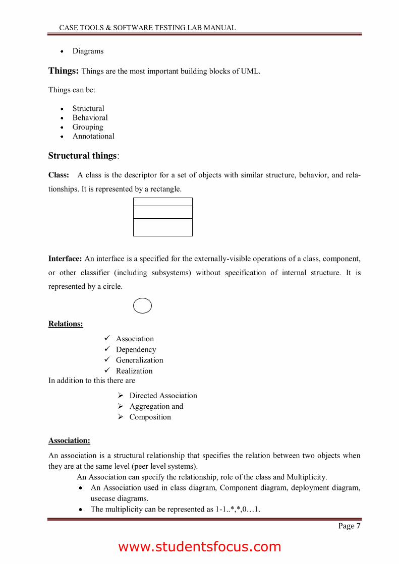
Class: A class is the descriptor for a set of objects with similar structure, behavior, and rela-
tionships. It is represented by a rectangle.
Interface: An interface is a specified for the externally-visible operations of a class, component,
or other classifier (including subsystems) without specification of internal structure. It is
represented by a circle.
Relations:
9 Association 9 Dependency 9 Generalization 9 Realization
In addition to this there are
¾ Directed Association ¾ Aggregation and ¾ Composition
Association:
An association is a structural relationship that specifies the relation between two objects when they are at the same level (peer level systems). An Association can specify the relationship, role of the class and Multiplicity.
An Association used in class diagram, Component diagram, deployment diagram, usecase diagrams.
The multiplicity can be represented as 1-1..*,*,0…1.
www.studentsfocus.com
CASE TOOLS & SOFTWARE TESTING LAB MANUAL
Page 8
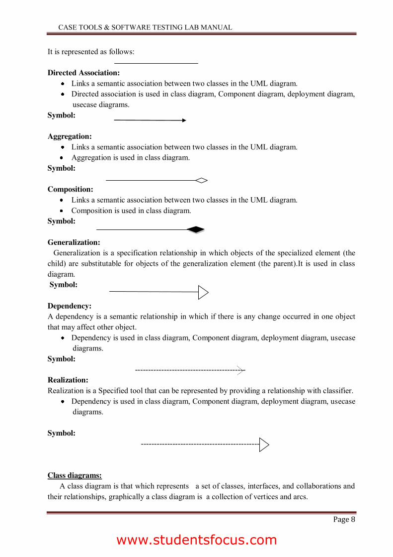
It is represented as follows: Directed Association:
Links a semantic association between two classes in the UML diagram. Directed association is used in class diagram, Component diagram, deployment diagram,
usecase diagrams. Symbol: Aggregation:
Links a semantic association between two classes in the UML diagram. Aggregation is used in class diagram.
Symbol: Composition:
Links a semantic association between two classes in the UML diagram. Composition is used in class diagram.
Symbol: Generalization: Generalization is a specification relationship in which objects of the specialized element (the child) are substitutable for objects of the generalization element (the parent).It is used in class diagram. Symbol: Dependency: A dependency is a semantic relationship in which if there is any change occurred in one object that may affect other object.
Dependency is used in class diagram, Component diagram, deployment diagram, usecase diagrams.
Symbol: ------------------------------------------ Realization: Realization is a Specified tool that can be represented by providing a relationship with classifier.
Dependency is used in class diagram, Component diagram, deployment diagram, usecase diagrams.
Symbol: ---------------------------------------------- Class diagrams: A class diagram is that which represents a set of classes, interfaces, and collaborations and their relationships, graphically a class diagram is a collection of vertices and arcs.
www.studentsfocus.com
CASE TOOLS & SOFTWARE TESTING LAB MANUAL
Page 9
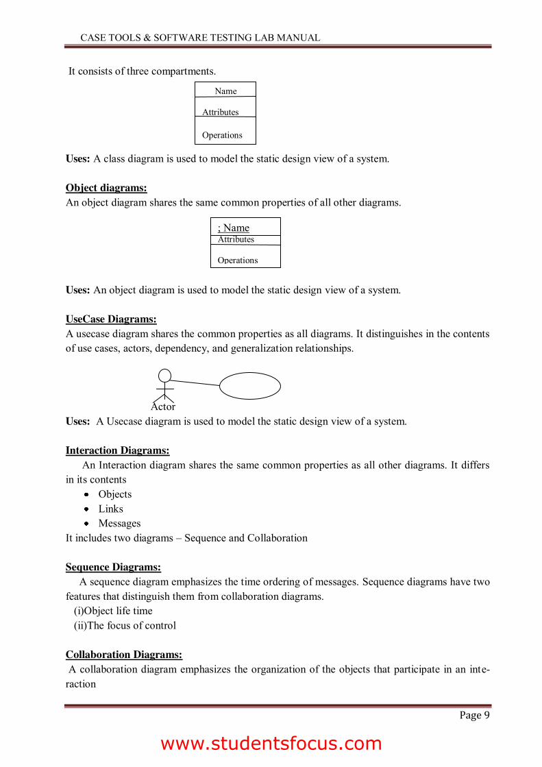
It consists of three compartments. Uses: A class diagram is used to model the static design view of a system. Object diagrams: An object diagram shares the same common properties of all other diagrams. Uses: An object diagram is used to model the static design view of a system. UseCase Diagrams: A usecase diagram shares the common properties as all diagrams. It distinguishes in the contents of use cases, actors, dependency, and generalization relationships. Actor Uses: A Usecase diagram is used to model the static design view of a system. Interaction Diagrams: An Interaction diagram shares the same common properties as all other diagrams. It differs in its contents
Objects Links Messages
It includes two diagrams – Sequence and Collaboration Sequence Diagrams: A sequence diagram emphasizes the time ordering of messages. Sequence diagrams have two features that distinguish them from collaboration diagrams. (i)Object life time (ii)The focus of control Collaboration Diagrams: A collaboration diagram emphasizes the organization of the objects that participate in an inte-raction
Name Attributes Operations
; Name Attributes Operations
www.studentsfocus.com
CASE TOOLS & SOFTWARE TESTING LAB MANUAL
Page 10
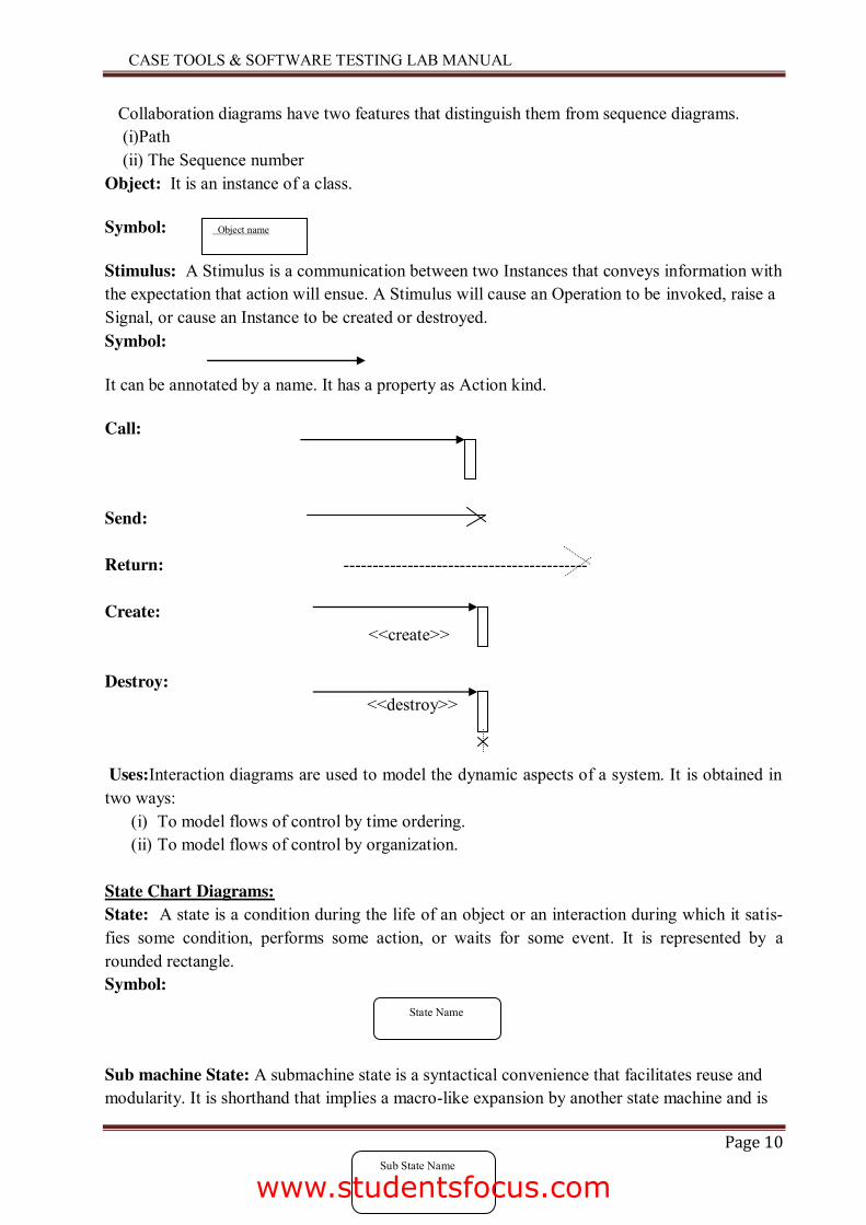
Collaboration diagrams have two features that distinguish them from sequence diagrams. (i)Path (ii) The Sequence number Object: It is an instance of a class.
Symbol:
Stimulus: A Stimulus is a communication between two Instances that conveys information with the expectation that action will ensue. A Stimulus will cause an Operation to be invoked, raise a Signal, or cause an Instance to be created or destroyed. Symbol:
It can be annotated by a name. It has a property as Action kind.
Call:
Send: Return: ------------------------------------------ Create: <<create>> Destroy: <<destroy>> Uses:Interaction diagrams are used to model the dynamic aspects of a system. It is obtained in two ways:
(i) To model flows of control by time ordering. (ii) To model flows of control by organization.
State Chart Diagrams: State: A state is a condition during the life of an object or an interaction during which it satis-fies some condition, performs some action, or waits for some event. It is represented by a rounded rectangle. Symbol:
Sub machine State: A submachine state is a syntactical convenience that facilitates reuse and modularity. It is shorthand that implies a macro-like expansion by another state machine and is
State Name
Sub State Name
Object name
www.studentsfocus.com
CASE TOOLS & SOFTWARE TESTING LAB MANUAL
Page 11
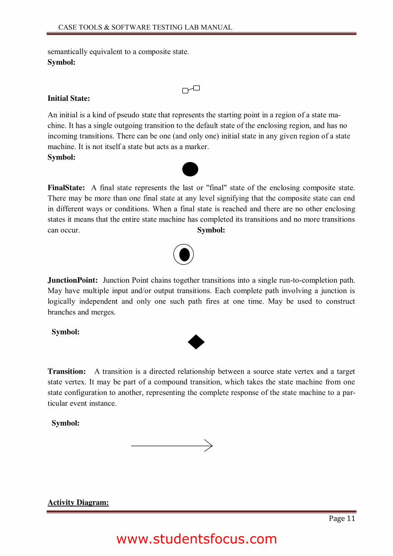
semantically equivalent to a composite state. Symbol:
Initial State:
An initial is a kind of pseudo state that represents the starting point in a region of a state ma-chine. It has a single outgoing transition to the default state of the enclosing region, and has no incoming transitions. There can be one (and only one) initial state in any given region of a state machine. It is not itself a state but acts as a marker. Symbol:
FinalState: A final state represents the last or "final" state of the enclosing composite state. There may be more than one final state at any level signifying that the composite state can end in different ways or conditions. When a final state is reached and there are no other enclosing states it means that the entire state machine has completed its transitions and no more transitions can occur. Symbol:
JunctionPoint: Junction Point chains together transitions into a single run-to-completion path. May have multiple input and/or output transitions. Each complete path involving a junction is logically independent and only one such path fires at one time. May be used to construct branches and merges.
Symbol:
Transition: A transition is a directed relationship between a source state vertex and a target state vertex. It may be part of a compound transition, which takes the state machine from one state configuration to another, representing the complete response of the state machine to a par-ticular event instance.
Symbol:
Activity Diagram:
www.studentsfocus.com
CASE TOOLS & SOFTWARE TESTING LAB MANUAL
Page 12
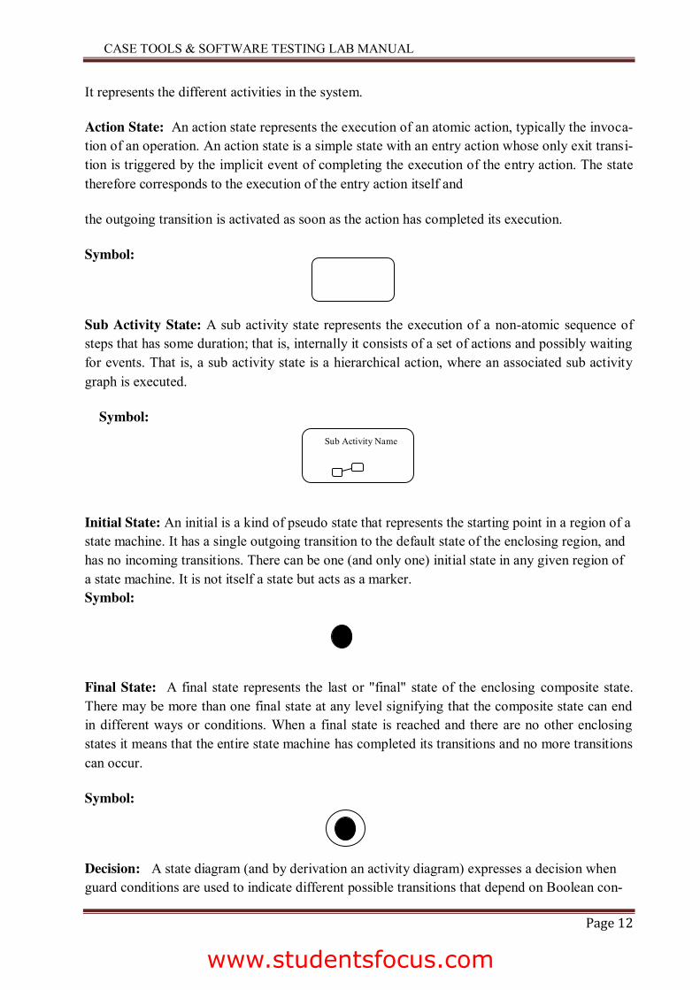
It represents the different activities in the system.
Action State: An action state represents the execution of an atomic action, typically the invoca-tion of an operation. An action state is a simple state with an entry action whose only exit transi-tion is triggered by the implicit event of completing the execution of the entry action. The state therefore corresponds to the execution of the entry action itself and
the outgoing transition is activated as soon as the action has completed its execution.
Symbol:
Sub Activity State: A sub activity state represents the execution of a non-atomic sequence of steps that has some duration; that is, internally it consists of a set of actions and possibly waiting for events. That is, a sub activity state is a hierarchical action, where an associated sub activity graph is executed.
Symbol:
Initial State: An initial is a kind of pseudo state that represents the starting point in a region of a state machine. It has a single outgoing transition to the default state of the enclosing region, and has no incoming transitions. There can be one (and only one) initial state in any given region of a state machine. It is not itself a state but acts as a marker. Symbol:
Final State: A final state represents the last or "final" state of the enclosing composite state. There may be more than one final state at any level signifying that the composite state can end in different ways or conditions. When a final state is reached and there are no other enclosing states it means that the entire state machine has completed its transitions and no more transitions can occur.
Symbol:
Decision: A state diagram (and by derivation an activity diagram) expresses a decision when guard conditions are used to indicate different possible transitions that depend on Boolean con-
Sub Activity Name
www.studentsfocus.com
CASE TOOLS & SOFTWARE TESTING LAB MANUAL
Page 13
ditions of the owning object. Symbol:
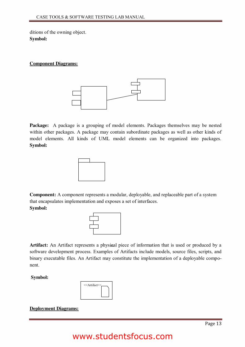
Component Diagrams:
Package: A package is a grouping of model elements. Packages themselves may be nested within other packages. A package may contain subordinate packages as well as other kinds of model elements. All kinds of UML model elements can be organized into packages. Symbol:
Component: A component represents a modular, deployable, and replaceable part of a system that encapsulates implementation and exposes a set of interfaces. Symbol:
Artifact: An Artifact represents a physical piece of information that is used or produced by a software development process. Examples of Artifacts include models, source files, scripts, and binary executable files. An Artifact may constitute the implementation of a deployable compo-nent.
Symbol:
Deployment Diagrams:
<<Artifact>>
www.studentsfocus.com
CASE TOOLS & SOFTWARE TESTING LAB MANUAL
Page 14
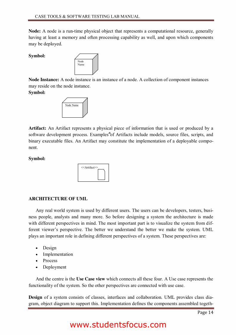
Node: A node is a run-time physical object that represents a computational resource, generally having at least a memory and often processing capability as well, and upon which components may be deployed.
Symbol:
Node Instance: A node instance is an instance of a node. A collection of component instances may reside on the node instance. Symbol:
Artifact: An Artifact represents a physical piece of information that is used or produced by a software development process. Examples of Artifacts include models, source files, scripts, and binary executable files. An Artifact may constitute the implementation of a deployable compo-nent.
Symbol:
ARCHITECTURE OF UML
Any real world system is used by different users. The users can be developers, testers, busi-ness people, analysts and many more. So before designing a system the architecture is made with different perspectives in mind. The most important part is to visualize the system from dif-ferent viewer’s perspective. The better we understand the better we make the system. UML plays an important role in defining different perspectives of a system. These perspectives are:
Design Implementation Process Deployment
And the centre is the Use Case view which connects all these four. A Use case represents the functionality of the system. So the other perspectives are connected with use case.
Design of a system consists of classes, interfaces and collaboration. UML provides class dia-gram, object diagram to support this. Implementation defines the components assembled togeth-
Node Name
Node Name
<<Artifact>>
www.studentsfocus.com
CASE TOOLS & SOFTWARE TESTING LAB MANUAL
Page 15
er to make a complete physical system. UML component diagram is used to support implemen-tation perspective.
Process defines the flow of the system. So the same elements as used in Design are also used to support this perspective.
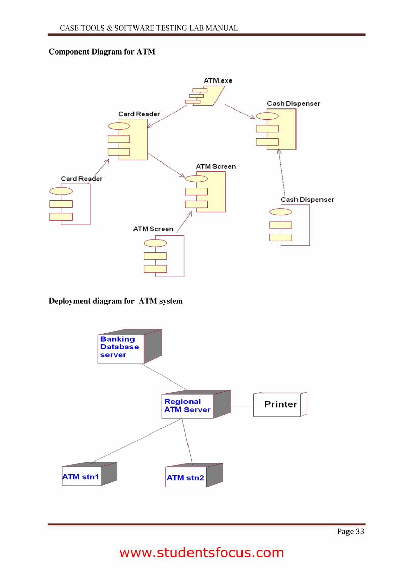
Deployment represents the physical nodes of the system that forms the hardware. UML dep-loyment diagram is used to support this perspective.
Automatic Teller Machine
USE CASE DIAGRAM
Overview:
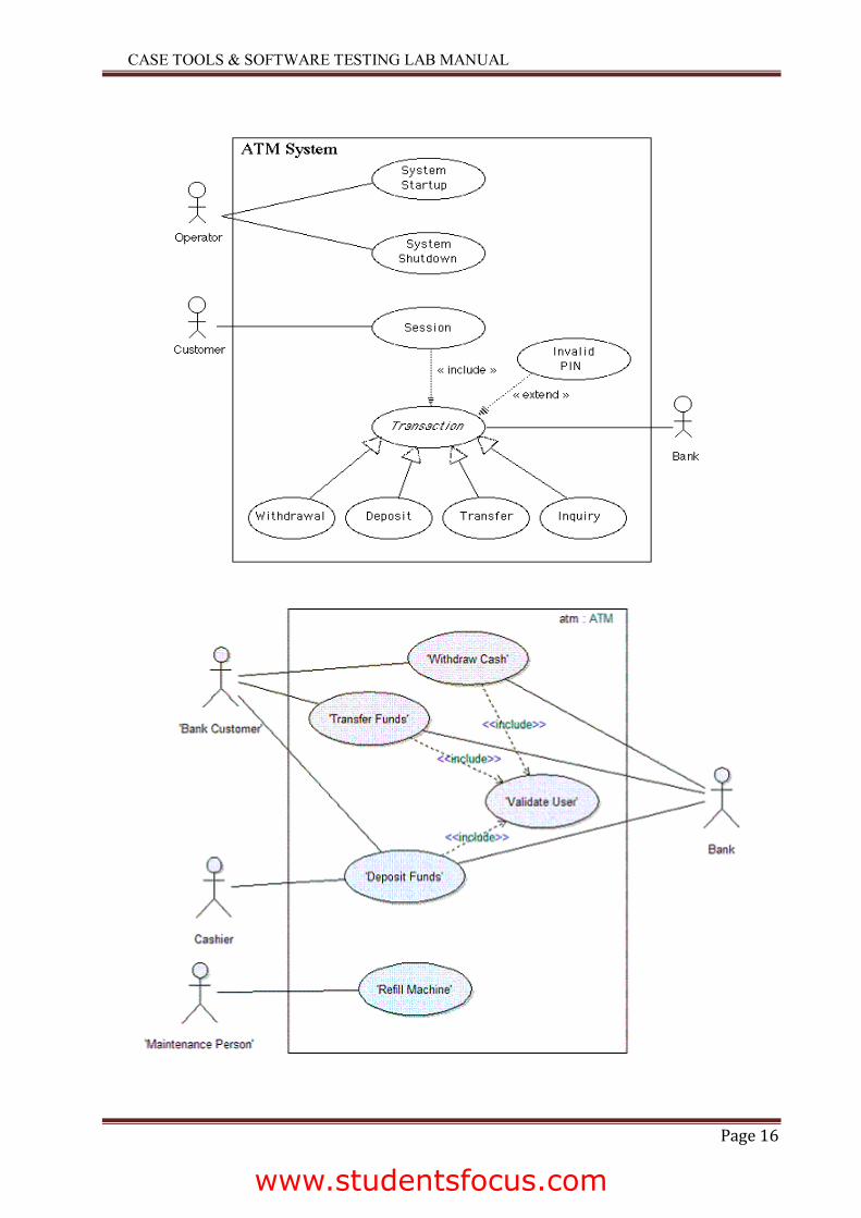
To model a system the most important aspect is to capture the dynamic behavior. To clarify a bit in details, dynamic behavior means the behavior of the system when it is running operating. So only static behavior is not sufficient to model a system rather dynamic behavior is more important than static behavior. In UML there are five diagrams available to model dynamic nature and use case diagram is one of them. Now as we have to discuss that the use case diagram is dynamic in nature there should be some internal or external factors for making the interaction. These internal and external agents are known as actors. So use case diagrams are consists of actors, use cases and their relationships. The diagram is used to model the system/subsystem of an application. A single use case diagram captures a particular functionality of a system. So to model the entire system numbers of use case diagrams are used.
Purpose:
The purpose of use case diagram is to capture the dynamic aspect of a system. But this definition is too generic to describe the purpose. Because other four diagrams (activity, se-quence, collaboration and State chart) are also having the same purpose. So we will look into some specific purpose which will distinguish it from other four diagrams. Use case diagrams are used to gather the requirements of a system including internal and external influences. These requirements are mostly design requirements. So when a system is analyzed to gather its func-tionalities use cases are prepared and actors are identified.
So in brief, the purposes of use case diagrams can be as follows:
Used to gather requirements of a system. Used to get an outside view of a system. Identify external and internal factors influencing the system. Show the interacting among the requirements are actors
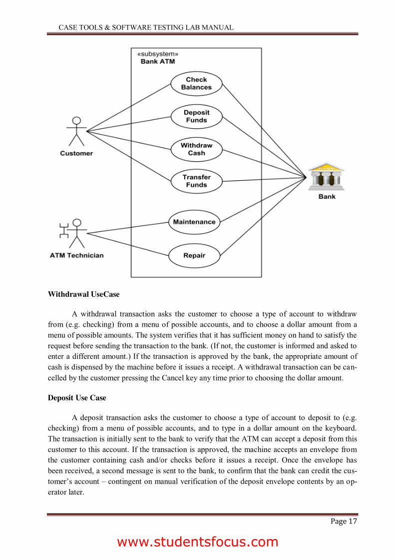
USE CASE DIAGRAM FOR ATM
www.studentsfocus.com
CASE TOOLS & SOFTWARE TESTING LAB MANUAL
Page 16
www.studentsfocus.com
CASE TOOLS & SOFTWARE TESTING LAB MANUAL
Page 17
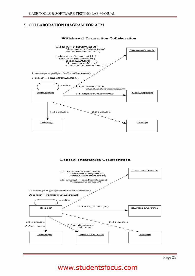
Withdrawal UseCase
A withdrawal transaction asks the customer to choose a type of account to withdraw from (e.g. checking) from a menu of possible accounts, and to choose a dollar amount from a menu of possible amounts. The system verifies that it has sufficient money on hand to satisfy the request before sending the transaction to the bank. (If not, the customer is informed and asked to enter a different amount.) If the transaction is approved by the bank, the appropriate amount of cash is dispensed by the machine before it issues a receipt. A withdrawal transaction can be can-celled by the customer pressing the Cancel key any time prior to choosing the dollar amount.
Deposit Use Case
A deposit transaction asks the customer to choose a type of account to deposit to (e.g. checking) from a menu of possible accounts, and to type in a dollar amount on the keyboard. The transaction is initially sent to the bank to verify that the ATM can accept a deposit from this customer to this account. If the transaction is approved, the machine accepts an envelope from the customer containing cash and/or checks before it issues a receipt. Once the envelope has been received, a second message is sent to the bank, to confirm that the bank can credit the cus-tomer’s account – contingent on manual verification of the deposit envelope contents by an op-erator later.
www.studentsfocus.com
CASE TOOLS & SOFTWARE TESTING LAB MANUAL
Page 18
A deposit transaction can be cancelled by the customer pressing the Cancel key any time prior to inserting the envelope containing the deposit. The transaction is automatically cancelled if the customer fails to insert the envelope containing the deposit within a reasonable period of time after being asked to do so.
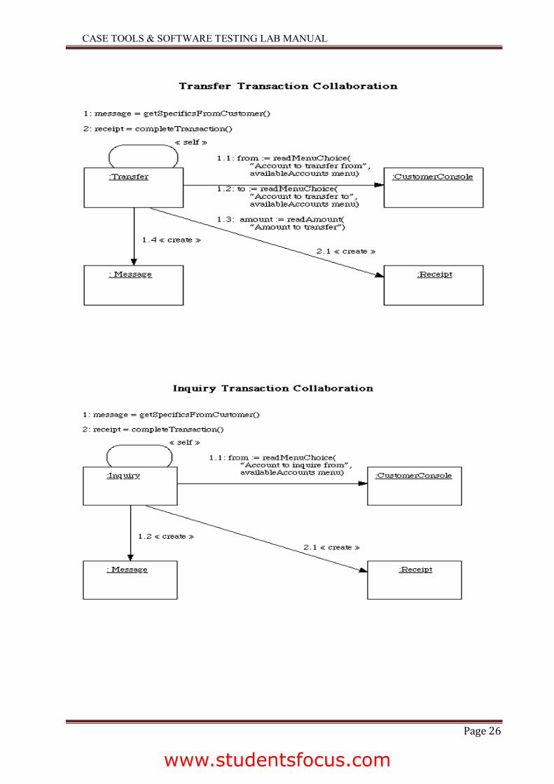
Transfer UseCase
A transfer transaction asks the customer to choose a type of account to transfer from (e.g. checking) from a menu of possible accounts, to choose a different account to transfer to, and to type in a dollar amount on the keyboard. No further action is required once the transaction is ap-proved by the bank before printing the receipt.
A transfer transaction can be cancelled by the customer pressing the Cancel key any time prior to entering a dollar amount.
Inquiry Use Case
An inquiry transaction asks the customer to choose a type of account to inquire about from a menu of possible accounts. No further action is required once the transaction is approved by the bank before printing the receipt. An inquiry transaction can be cancelled by the customer pressing the Cancel key any time prior to choosing the account to inquire about.
ValidateUser usecase:
This usecase is for validate the user i.e check the pin number, when the bank reports that the customer’s transaction is disapproved due to an invalid PIN. The customer is required to re-enter the PIN and the original request is sent to the bank again. If the bank now approves the transaction, or disapproves it for some other reason, the original use case is continued; otherwise the process of re-entering the PIN is repeated. Once the PIN is successfully re-entered
If the customer fails three times to enter the correct PIN, the card is permanently re-tained, a screen is displayed informing the customer of this and suggesting he/she contact the bank, and the entire customer session is aborted.
PrintBill usecase
This usecase is for printing corresponding bill after transactions(withdraw or deposit ,or balance enquiry, transfer) are completed.
Update Account
This usecase is for updating corresponding user accounts after transactions (withdraw or deposit or transfer) are completed.
www.studentsfocus.com
CASE TOOLS & SOFTWARE TESTING LAB MANUAL
Page 19
2. CLASS DIAGRAM
Overview:
The class diagram is a static diagram. It represents the static view of an application. Class diagram is not only used for visualizing, describing and documenting different aspects of a system but also for constructing executable code of the software application. The class diagram describes the attributes and operations of a class and also the constraints imposed on the system. The class diagram shows a collection of classes, interfaces, associations, collaborations and con-straints. It is also known as a structural diagram.
Purpose:
The purpose of the class diagram is to model the static view of an application. The class diagrams are the only diagrams which can be directly mapped with object oriented languages and thus widely used at the time of construction. The UML diagrams like activity diagram, se-quence diagram can only give the sequence flow of the application but class diagram is a bit dif-ferent. So it is the most popular UML diagram in the coder community. So the purpose of the class diagram can be summarized as:
Analysis and design of the static view of an application. Describe responsibilities of a system. Base for component and deployment diagrams. Forward and reverse engineering.
Contents:
Class diagrams commonly contain the following things
Classes Interfaces Collaborations Dependency, generalization and association relationships
www.studentsfocus.com
CASE TOOLS & SOFTWARE TESTING LAB MANUAL
Page 20
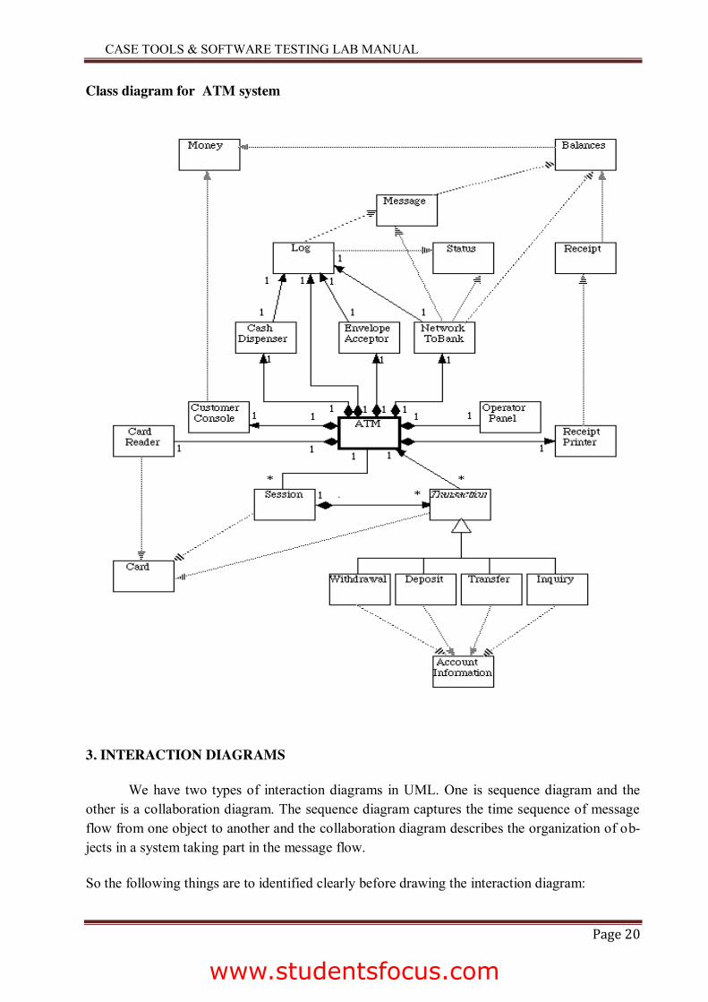
Class diagram for ATM system
3. INTERACTION DIAGRAMS
We have two types of interaction diagrams in UML. One is sequence diagram and the other is a collaboration diagram. The sequence diagram captures the time sequence of message flow from one object to another and the collaboration diagram describes the organization of ob-jects in a system taking part in the message flow.
So the following things are to identified clearly before drawing the interaction diagram:
www.studentsfocus.com
CASE TOOLS & SOFTWARE TESTING LAB MANUAL
Page 21
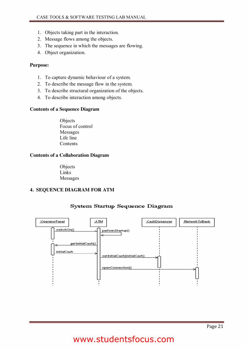
1. Objects taking part in the interaction. 2. Message flows among the objects. 3. The sequence in which the messages are flowing. 4. Object organization.
Purpose:
1. To capture dynamic behaviour of a system. 2. To describe the message flow in the system. 3. To describe structural organization of the objects. 4. To describe interaction among objects.
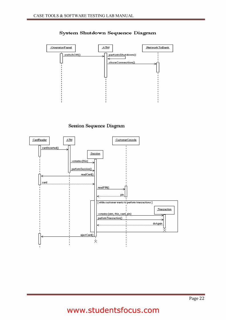
Contents of a Sequence Diagram
Objects Focus of control Messages Life line Contents
Contents of a Collaboration Diagram
Objects Links Messages
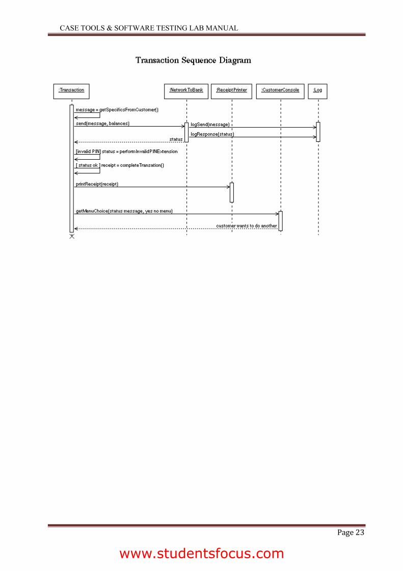
4. SEQUENCE DIAGRAM FOR ATM
www.studentsfocus.com
CASE TOOLS & SOFTWARE TESTING LAB MANUAL
Page 22
www.studentsfocus.com
CASE TOOLS & SOFTWARE TESTING LAB MANUAL
Page 23
www.studentsfocus.com
CASE TOOLS & SOFTWARE TESTING LAB MANUAL
Page 24
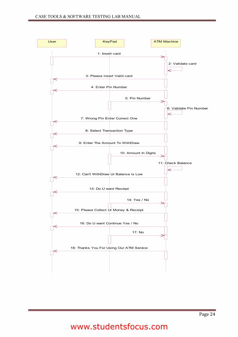
User KeyPad ATM Machine
1: Insert card
2: Validate card
3: Please insert Valid card
4: Enter Pin Number
5: Pin Number
6: Validate Pin Number
7: Wrong Pin Enter Currect One
8: Select Transaction Type
9: Enter The Amount To WithDraw
10: Amount In Digits
11: Check Balance
12: Can't WithDraw Ur Balance is Low
13: Do U want Receipt
14: Yes / No
15: Please Collect Ur Money & Receipt
16: Do U want Continue Yes / No
17: No
18: Thanks You For Using Our ATM Service
www.studentsfocus.com
CASE TOOLS & SOFTWARE TESTING LAB MANUAL
Page 25
5. COLLABORATION DIAGRAM FOR ATM
www.studentsfocus.com
CASE TOOLS & SOFTWARE TESTING LAB MANUAL
Page 26
www.studentsfocus.com
CASE TOOLS & SOFTWARE TESTING LAB MANUAL
Page 27
6. STATE DIAGRAM
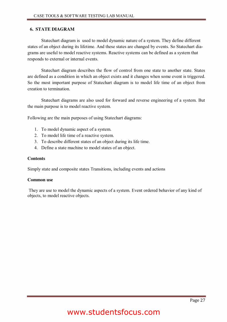
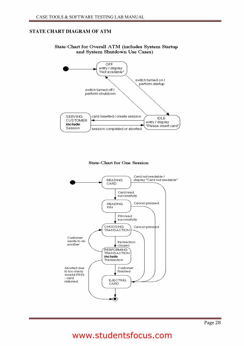
Statechart diagram is used to model dynamic nature of a system. They define different states of an object during its lifetime. And these states are changed by events. So Statechart dia-grams are useful to model reactive systems. Reactive systems can be defined as a system that responds to external or internal events.
Statechart diagram describes the flow of control from one state to another state. States are defined as a condition in which an object exists and it changes when some event is triggered. So the most important purpose of Statechart diagram is to model life time of an object from creation to termination.
Statechart diagrams are also used for forward and reverse engineering of a system. But the main purpose is to model reactive system.
Following are the main purposes of using Statechart diagrams:
1. To model dynamic aspect of a system. 2. To model life time of a reactive system. 3. To describe different states of an object during its life time. 4. Define a state machine to model states of an object.
Contents
Simply state and composite states Transitions, including events and actions
Common use
They are use to model the dynamic aspects of a system. Event ordered behavior of any kind of objects, to model reactive objects.
www.studentsfocus.com
CASE TOOLS & SOFTWARE TESTING LAB MANUAL
Page 28
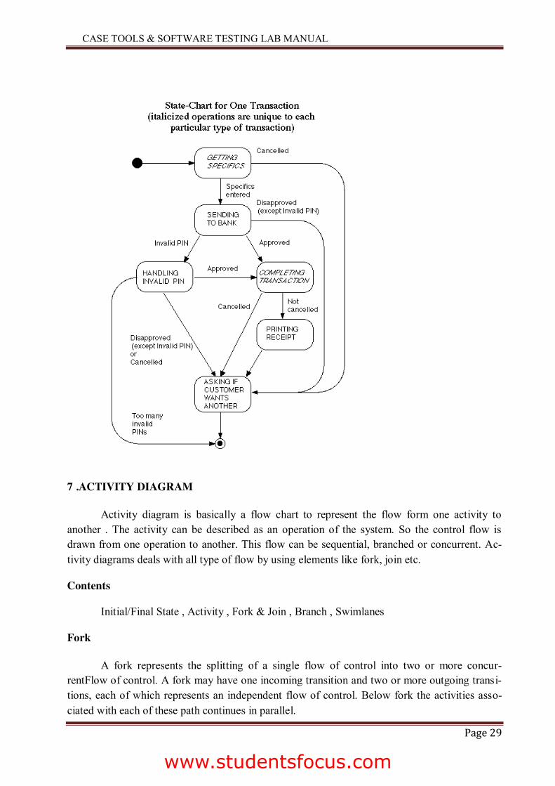
STATE CHART DIAGRAM OF ATM
www.studentsfocus.com
CASE TOOLS & SOFTWARE TESTING LAB MANUAL
Page 29
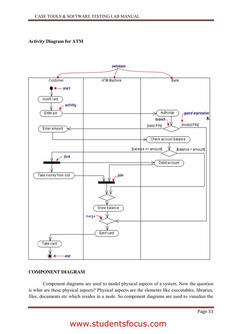
7 .ACTIVITY DIAGRAM
Activity diagram is basically a flow chart to represent the flow form one activity to another . The activity can be described as an operation of the system. So the control flow is drawn from one operation to another. This flow can be sequential, branched or concurrent. Ac-tivity diagrams deals with all type of flow by using elements like fork, join etc.
Contents
Initial/Final State , Activity , Fork & Join , Branch , Swimlanes
Fork
A fork represents the splitting of a single flow of control into two or more concur-rentFlow of control. A fork may have one incoming transition and two or more outgoing transi-tions, each of which represents an independent flow of control. Below fork the activities asso-ciated with each of these path continues in parallel.
www.studentsfocus.com
CASE TOOLS & SOFTWARE TESTING LAB MANUAL
Page 30
Join
A join represents the synchronization of two or more concurrent flows of control. A join may have two or more incoming transition and one outgoing transition. Above the join the activ-ities associated with each of these paths continues in parallel.
Branching
A branch specifies alternate paths takes based on some Boolean expression Branch is represented by diamond Branch may have one incoming transition and two or more outgoing one on each outgoing transition, you place a Boolean expression shouldn’t overlap but they should cover all possibilities.
Swimlane:
Swimlanes are useful when we model workflows of business processes to partition the activity states on an activity diagram into groups. Each group representing the business organi-zation responsible for those activities ,these groups are called Swimlanes .
www.studentsfocus.com
CASE TOOLS & SOFTWARE TESTING LAB MANUAL
Page 31
Activity Diagram for ATM
8.
COMPONENT DIAGRAM
Component diagrams are used to model physical aspects of a system. Now the question is what are these physical aspects? Physical aspects are the elements like executables, libraries, files, documents etc which resides in a node. So component diagrams are used to visualize the
www.studentsfocus.com
CASE TOOLS & SOFTWARE TESTING LAB MANUAL
Page 32
organization and relationships among components in a system. These diagrams are also used to make executable systems.
Purpose:
Component diagrams can be described as a static implementation view of a system. Stat-ic implementation represents the organization of the components at a particular moment. A sin-gle component diagram cannot represent the entire system but a collection of diagrams are used to represent the whole.
Before drawing a component diagram the following artifacts are to be identified clearly:
Files used in the system. Libraries and other artifacts relevant to the application. Relationships among the artifacts.
Now after identifying the artifacts the following points needs to be followed:
Use a meaningful name to identify the component for which the diagram is to be drawn. Prepare a mental layout before producing using tools. Use notes for clarifying important points.
Now the usage of component diagrams can be described as:
1. Model the components of a system. 2. Model database schema. 3. Model executables of an application. 4. Model system’s source code.
Contents
Components, Interfaces, Relationships
www.studentsfocus.com
CASE TOOLS & SOFTWARE TESTING LAB MANUAL
Page 33
Component Diagram for ATM
Deployment diagram for ATM system
www.studentsfocus.com


