26
R M-FL60/FL61-EN-V1.3 Smart Flow Sensors Manual

R
M-FL60/FL61-EN-V1.3
Smart Flow Sensors Manual

Choose the adaptor US0029 for low flow rate.
4.
When installing Ex-Proof wire, it is necessary to tighten it with wrench. Torque:1.5Nm
5.
Please purchase ema qualified Ex-proof wire for this Ex-proof product as the requirement.
6.
The housing of product in the pipe should be correctly connected with the equipotential grounding system.
7.
Do not open when an explosive dust asmosphere is present.8.
2.Screw a suitable adapter to the joint . (Fig.4)3.
4.The insertion depth for the probe: The minimum insertion depth to the pipeline ≧ 12mm. To ensure correct depth, the user can use ema adapter. (optional order)

RELAYDC
RELAYAC BK
BK
L+
L-

The current flow rate is within the range of the display. (LED bar Green)
The current flow rate exceeds the flow range (LED 9 Flash)
The current flow is too low. The indication of no flow in the pipe. (LED 0 Flash)
Setting buttons:FL-YellowFE-Grey

10

122411

·Hysteresis is 2~4 cm/s (Suitable for water) when it is adjusted to high flow rate between 0~100 cm/s.
3...100
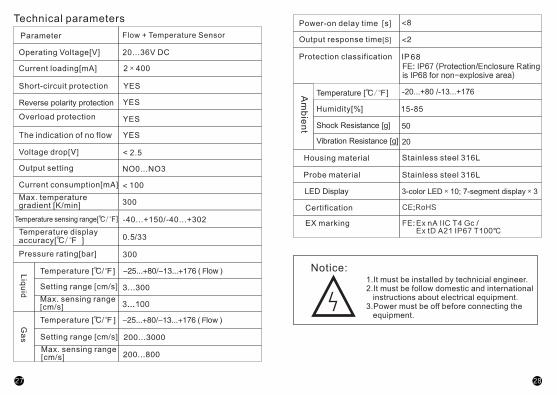
Power-on delay times[s]
Output response time[s]
±2...±10cm/sFactory setting as 25℃ water
The indication of no flow
IP68
142413
-25...+100/-13...+212
CE;RoHSCertification
20...36DC
Accuracy[%]
EX marking Ex nA IIC T4 Gc /Ex tD A21 IP67 T100℃
FE:
FE: IP67 (Protection/Enclosure Rating is IP68 for non-explosive area)

R
M-FL62-EN-V1.3
Note: Standard length of probe is about 45 mm, there is also extended length of probe 100/200 mm, and titanium alloy probe for corrosion protection for your choice.
1. Please confirm the purchasing item is switching or analogue or Relay output and install the product according to the operating voltage.2. For AC RELAY sensor, add the fuse ≤5A (Fast action) or cable with shield.3. Please purchase ema qualified Ex-proof product.
2415

24182417
Choose the adaptor US0029 for low flow rate.
4.
When installing Ex-Proof wire, it is necessary to tighten it with wrench. Torque:1.5Nm
5.
Please purchase ema qualified Ex-proof wire for this Ex-proof product as the requirement.
6.
The housing of product in the pipe should be correctly connected with the equipotential grounding system.
7.
8. Do not open when an explosive dust asmosphere is present.
2.Screw a suitable adapter to the joint . (Fig.4)3.
4.The insertion depth for the probe: The minimum insertion depth to the pipeline ≧ 12mm. To ensure correct depth, the user can use ema adapter. (optional order)

TX
FX
TX
COMCOM COMCOM
N.O N.O
TX TX TX
COM
N.O
COM
N.O
NO0 NO1 NO21 NO3
NO0 NO1 NO21 NO3
NO0 NO1 NO21 NO3
Relay and PNP output
NPN Connection
TX
FX
TX
FX
TX
FX
TX
FX
TX
FX
TX
FX
TX
FX
Analogue output
4-20mA
NO0
OUT
TX
COM
N.O
P
TX
FX
NO11
TX
COM
N.O
NO2
TX
COM
N.O
NO3
COM
TX
N.O
Relay and NPN outputPNP Connection
PNP/NPN output RELAY / PNP output Analogue output
202419
PIN1:L+ Positive pole (BN)
PIN2:Flow, PNP/NPN (WH)
PIN3:L- Negative pole (BU)
PIN4:Temp., PNP/NPN (BK)
PIN5:P, Programming wire (RD)
PIN1:L+ Positive pole (BN)
PIN2:Flow, 4...20 mA (WH)
PIN3:L- Negative pole (BU)
PIN4:Temp., 4...20 mA (BK)
PIN5:P, Programming wire (RD)
PIN1:L+ Positive pole (BN)
PIN2:Flow, Relay COM (WH)
PIN3:L- Negative pole (BU)
PIN4:Temp., PNP/NPN (BK)
PIN5:Flow, Relay NO (RD)

The current flow rate is within the range of the display. (LED bar Green)
The current flow rate exceeds the flow range (LED 9 Flash)
The current flow is too low. The indication of no flow in the pipe. (LED 0 Flash)
Analogue outputStart pointASP -40℃ ~ +140℃
-40℉ ~ +284℉
AEP Analogue outputEnd point
-30℃ ~ +150℃-22℉ ~ +302℉
Switchingoutput
2221

2423
Flow
Temperature low point record setting

·Hysteresis is 2~4 cm/s (Suitable for water) when it is adjusted to high flow rate between 0~100 cm/s.
2625
3...100
The indication of no flow
2827
1.It must be installed by technicial engineer.2.It must be follow domestic and international instructions about electrical equipment.3.Power must be off before connecting the equipment.
CE;RoHSCertification
EX marking Ex nA IIC T4 Gc /Ex tD A21 IP67 T100℃
FE:
FE: IP67 (Protection/Enclosure Rating is IP68 for non-explosive area)

M-FL63-EN-V1.3
29

。
3231
Choose the adaptor US0029 for low flow rate.
4.
When installing Ex-Proof wire, it is necessary to tighten it with wrench. Torque:1.5Nm
5.
Please purchase ema qualified Ex-proof wire for this Ex-proof product as the requirement.
6.
The housing of product in the pipe should be correctly connected with the equipotential grounding system.
7.
Do not open when an explosive dust asmosphere is present.8.
2.Screw a suitable adapter to the joint . (Fig.4)3.
4.The insertion depth for the probe: The minimum insertion depth to the pipeline ≧ 12mm. To ensure correct depth, the user can use ema adapter. (optional order)

4Pinout
3433
Potentiometer setting:FL-YellowFE-Grey

SP setting
tt
Application Liquid and gas
Operation voliage[v] 10...36DC
Max.overload current [mA] 400
Reverse Polarity protection
Overload protection
Short-circuit protection
The indication of no flow
Output function PNP/NPN NO,PNP/NPN NC
Yes
3635

Probe material
M-FL64-EN-V1.3
68IP
R
37
1.It must be installed by technicial engineer.2.It must be follow domestic and international instructions about electrical equipment.3.Power must be off before connecting the equipment.4.Please purchase ema qualified Ex-proof wire for this Ex-proof product.
CE;RoHSCertification
EX marking Ex nA IIC T4 Gc /Ex tD A21 IP67 T100℃
FE:
FE: IP67 (Protection/Enclosure Rating is IP68 for non-explosive area)

4039
Choose the adaptor US0029 for low flow rate.
4.
2.Screw a suitable adapter to the joint . (Fig.4)3.
4.The insertion depth for the probe: The minimum insertion depth to the pipeline ≧ 12mm. To ensure correct depth, the user can use ema adapter. (optional order)

NO/NC setting via menu NO/NC setting via menu
Connection
(RELAY)
RELAYDC
RELAYAC BK
BK
L+
L-
4241

The current flow rate is within the range of the display. (LED bar Green)
The current flow rate exceeds the flow range (LED 9 Flash)
The current flow is too low. The indication of no flow in the pipe. (LED 0 Flash)
4443

4645

4847

The indication of no flow
±2...±10cm/s
3...100
·Hysteresis is 2~4 cm/s (Suitable for water) when it is adjusted to high flow rate between 0~100 cm/s.
Factory setting as25℃ water Accuracy[%]
5049
20...36DC

1. Please confirm the purchasing item is switching or Relay output and install the product according to the operating voltage.2. For AC RELAY sensor, add the fuse ≤5A (Fast action) or cable with shield.
5251
1.It must be installed by technicial engineer.2.It must be follow domestic and international instructions about electrical equipment.3.Power must be off before connecting the equipment.


