This is a preprint of a paper intended for publication in a journal or proceedings. Since changes may not be made before publication, this preprint should not be cited or reproduced without permission of the author. This document was prepared as an account of work sponsored by an agency of the United States Government. Neither the United States Government nor any agency thereof, or any of their employees, makes any warranty, expressed or implied, or assumes any legal liability or responsibility for any third party’s use, or the results of such use, of any information, apparatus, product or process disclosed in this report, or represents that its use by such third party would not infringe privately owned rights. The views expressed in this paper are not necessarily those of the United States Government or the sponsoring agency. INL/CON-06-11092 PREPRINT Atmospheric-Pressure Plasma Process And Applications SOHN International Symposium On Advanced Processing of Metals and Materials; Principles, Technologies and Industrial Practice Peter Kong September 2006
Transcript
This is a preprint of a paper intended for publication in a journal or proceedings. Since changes may not be made before publication, this preprint should not be cited or reproduced without permission of the author. This document was prepared as an account of work sponsored by an agency of the United States Government. Neither the United States Government nor any agency thereof, or any of their employees, makes any warranty, expressed or implied, or assumes any legal liability or responsibility for any third party’s use, or the results of such use, of any information, apparatus, product or process disclosed in this report, or represents that its use by such third party would not infringe privately owned rights. The views expressed in this paper are not necessarily those of the United States Government or the sponsoring agency.
INL/CON-06-11092PREPRINT
Atmospheric-PressurePlasma Process And Applications
SOHN International Symposium On Advanced Processing of Metals and Materials; Principles, Technologies and Industrial Practice
Peter Kong
September 2006
ATMOSPHERIC-PRESSURE PLASMA PROCESS AND APPLICATIONS
Peter Kong
Idaho National Laboratory; P.O. Box 1625; Idaho Falls, ID 83415-2210 USA
Keywords: Plasma, Process, Applications
Abstract
This paper provides a general discussion of atmospheric-pressure plasma generation, processes, and applications. There are two distinct categories of atmospheric-pressure plasmas: thermal and nonthermal. Thermal atmospheric-pressure plasmas include those produced in high intensity arcs, plasma torches, or in high intensity, high frequency discharges. Although nonthermal plasmas are at room temperatures, they are extremely effective in producing activated species, e.g., free radicals and excited state atoms. Thus, both thermal and nonthermal atmospheric-pressure plasmas are finding applications in a wide variety of industrial processes, e.g. waste destruction, material recovery, extractive metallurgy, powder synthesis, and energy conversion. A brief discussion of recent plasma technology research and development activities at the Idaho National Laboratory is included.
Introduction
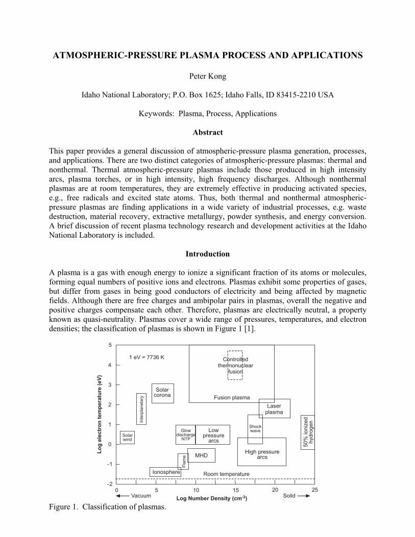
A plasma is a gas with enough energy to ionize a significant fraction of its atoms or molecules, forming equal numbers of positive ions and electrons. Plasmas exhibit some properties of gases, but differ from gases in being good conductors of electricity and being affected by magnetic fields. Although there are free charges and ambipolar pairs in plasmas, overall the negative and positive charges compensate each other. Therefore, plasmas are electrically neutral, a property known as quasi-neutrality. Plasmas cover a wide range of pressures, temperatures, and electron densities; the classification of plasmas is shown in Figure 1 [1].
0 5 10 15-2
0
2
4
20 25
Log Number Density (cm )-3
1 eV = 7736 K
Room temperature
Vacuum Solid
-1
1
3
5
Lo
ge
lec
tro
nte
mp
era
ture
(eV
)
Fusion plasma
Solarcorona
Lowpressure
arcs
Glowdischarge
NTP
Shockwave
Laserplasma
High pressurearcs
Solarwind
MHD
Controlledthermonuclear
fusion
Inte
rpla
neta
ry
50
%io
niz
ed
hyd
rog
en
Ionosphere
Fla
me
Figure 1. Classification of plasmas.
There are two main types of plasmas, atmospheric pressure and low pressure. For atmospheric-pressure plasmas, the mean free paths between electrons and heavy particles are extremely short and, therefore, the plasma is collision dominated. Under such conditions, local thermodynamic
equilibrium (LTE) may prevail, which includes kinetic equilibrium (Te Th where Te = electron temperature and Th = heavy particle or sensible temperature) as well as chemical equilibrium, i.e. particle concentrations in LTE plasmas are only a function of temperature. In contrast, in low-pressure plasmas, the mean free paths are much longer and, therefore, collisions between particles are much less frequent. Under these conditions, the electron temperature is much higher than the heavy particle temperatures, i.e. Te >> Th (Figure 2) [1]. Even though ionization in low-pressure plasmas is very high, the gas density in this type of plasma is extremely low. Therefore, thermal equilibrium cannot be achieved between electrons and heavy particles during collisions. Consequently, the heavy gas particles remain cold after collisions. Plasmas produced in various types of glow discharges, in low intensity high frequency discharges, and in corona discharges are typical examples of cold plasmas.
10-4
10-3
10-2
10-1
100
101
102
103
102
103
104
105
Ti
Te
Th
One atmosphere
Pressure (kPa)
Te
mp
era
ture
(K)
Figure 2. Variation of electron and heavy particle temperature with pressure.
Within atmospheric-pressure plasmas, there are two distinct categories, thermal and nonthermal.
In thermal plasmas Te Th (LTE exists). The core gas temperatures in thermal plasmas are well above 10,000 K and the gas is significantly ionized. The atmospheric nonthermal plasmas have very high electron temperatures, Te, while the sensible temperatures, Th, remain ambient. Atmospheric nonthermal plasmas have a low degree of ionization and the density of charged species is low. The electrons and ions never achieve local thermodynamic equilibrium. For this reason, the gas is at room temperature. However, atmospheric nonthermal plasmas have a high density of activated species, i.e. reactive free radicals and excited state atoms. Thus, nonthermal plasmas are very reactive.
Atmospheric-pressure plasmas have a wide variety of potential industrial applications. They are used in extractive metallurgy; metal recovery; novel nanomaterial synthesis; refractory and wear resistant coatings deposition; chemical synthesis; energy conversion; industrial, medical, and nuclear waste destruction; engine combustion enhancement; and exhaust gas pollutants clean up. This paper presents an overview of the use of atmospheric-pressure plasma processes in several of these areas.
Atmospheric-Pressure Plasma Generation
Plasma is generated by the passage of an electric current through a gas. Since gases at ambient temperatures are excellent insulators, a sufficient number of charge carriers have to be generated to make the gas electrically conducting. Passing an electrical current through an ionized gas leads to phenomena known as gaseous discharges. Such gaseous discharges are the most common, though not the only, means for producing plasmas.
A thermal plasma may be generated by passing a gas through a high intensity electric arc discharge, which will heat the gas by resistive and radiative heating to very high temperatures within milliseconds, or through high intensity and high frequency arc discharges. The arcs are initiated by electron emission through a process known as thermoionic emission. The thermoionic emission of bonded electrons from a solid surface is caused by supplying a large amount of heat to the surface. If the surface temperature of the emitter is not high enough for pure thermoionic emission of electrons, a strong field is used to pull out the electrons. This process is called thermoionic plus field emission of electrons. Arc initiation by a high frequency arc starter belongs to this process. Plasma generators are classed as direct current (DC), alternating current (AC), radio frequency (RF), or microwave (MW) plasma generators. The DC- and AC-generated plasmas are electrode-discharged plasmas, while RF- or MW-generated plasmas are referred to as inductively-coupled plasmas. The inductively-coupled plasmas are electrodeless discharged plasmas. Finally, thermal plasmas may also be produced by heating gases (vapors) in a high temperature furnace or in a combustion flame. Due to the inherent temperature limitations, this method is restricted to metal vapors with very low ionization potentials. In a flame-ionized gas, only the metal vapor is ionized, not the gas molecules, so the flame-ionized gas is not a real thermal plasma.
Atmospheric nonthermal plasmas include the corona discharge, dielectric barrier discharge, and surface plasma discharge. These discharges are generated by electron avalanche and streamer formation mechanisms. Ionization in nonthermal plasmas is not very high, but it is very effective in generating high concentrations of reactive radicals.
Waste Destruction and Material Recovery with Thermal Plasmas
The destruction of toxic and hazardous wastes is a serious concern for this country. Manufacturing industries, communities, hospitals, farming operations, and educational and research institutions all produce hazardous wastes [2]. Nuclear operations, particularly at the Department of Energy sites, have produced high-level radioactive waste from the nuclear materials separation process, materials contaminated with transuranics, and low-level radioactive wastes. For example, the wastes at the Idaho National Laboratory (INL) [3] include solid combustibles, organic and inorganic sludge, hazardous organic compounds, structural metals, construction debris, and soil contaminated with long-lived radionuclides. There are also large stockpiles of toxic military wastes worldwide that present an environmental hazard.
There are three main options for waste disposal: (1) burial, (2) treatment followed by burial, and (3) recycling to recover raw material and energy followed by disposal of residues [4]. With the amount of available land shrinking, burial is becoming a less viable option. Incineration was once a treatment option, but it has technological limitations, e.g., treatment of large offgas volumes and fly ash. Recently, attention has focused on developing thermal plasmas for the destruction of hazardous wastes and stabilization of nuclear wastes. Thermal plasmas possess several favorable characteristics for waste destruction: (1) very high temperatures, (2) very high energy density, (3) very fast process kinetics, (4) homogeneity and readily controlled, (5) turn key system, (6) very small footprint, and (7) useful material recovery. Since the late 1980s,
plasma waste destruction systems significantly greater than 0.5 MW have been commercialized in Europe and North America. Several examples of plasma waste destruction and material recovery are given below; interested readers should refer to the excellent review of thermal plasma waste destruction technology by J. Heberlein [5].
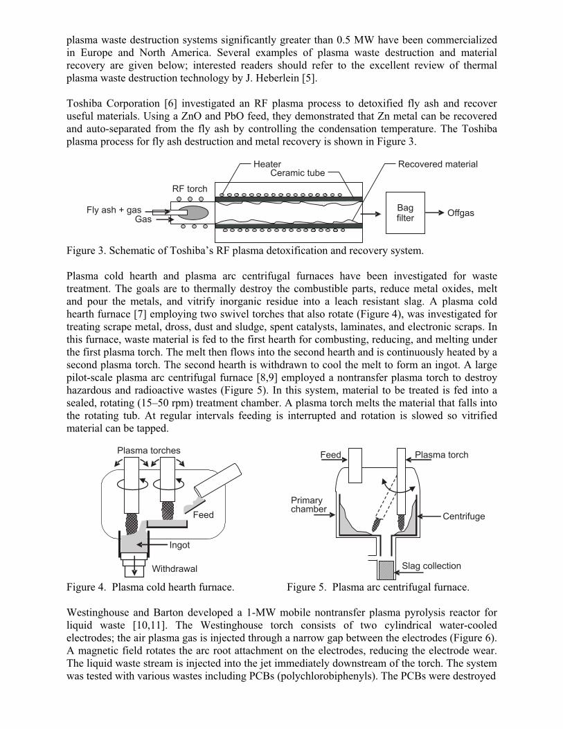
Toshiba Corporation [6] investigated an RF plasma process to detoxified fly ash and recover useful materials. Using a ZnO and PbO feed, they demonstrated that Zn metal can be recovered and auto-separated from the fly ash by controlling the condensation temperature. The Toshiba plasma process for fly ash destruction and metal recovery is shown in Figure 3.
RF torch
Fly ash + gasGas
HeaterCeramic tube
Bagfilter
Offgas
Recovered material
Figure 3. Schematic of Toshiba’s RF plasma detoxification and recovery system.
Plasma cold hearth and plasma arc centrifugal furnaces have been investigated for waste treatment. The goals are to thermally destroy the combustible parts, reduce metal oxides, melt and pour the metals, and vitrify inorganic residue into a leach resistant slag. A plasma cold hearth furnace [7] employing two swivel torches that also rotate (Figure 4), was investigated for treating scrape metal, dross, dust and sludge, spent catalysts, laminates, and electronic scraps. In this furnace, waste material is fed to the first hearth for combusting, reducing, and melting under the first plasma torch. The melt then flows into the second hearth and is continuously heated by a second plasma torch. The second hearth is withdrawn to cool the melt to form an ingot. A large pilot-scale plasma arc centrifugal furnace [8,9] employed a nontransfer plasma torch to destroy hazardous and radioactive wastes (Figure 5). In this system, material to be treated is fed into a sealed, rotating (15–50 rpm) treatment chamber. A plasma torch melts the material that falls into the rotating tub. At regular intervals feeding is interrupted and rotation is slowed so vitrified material can be tapped.
Westinghouse and Barton developed a 1-MW mobile nontransfer plasma pyrolysis reactor for liquid waste [10,11]. The Westinghouse torch consists of two cylindrical water-cooled electrodes; the air plasma gas is injected through a narrow gap between the electrodes (Figure 6). A magnetic field rotates the arc root attachment on the electrodes, reducing the electrode wear. The liquid waste stream is injected into the jet immediately downstream of the torch. The system was tested with various wastes including PCBs (polychlorobiphenyls). The PCBs were destroyed
Waste stream feedPlasma gas
Reactionchamber
Plasma torch
Field coil
Scrubbing solution Offgas
Figure 6. Schematic of the Westinghouse 1 MW plasma pyrolysis reactor.
at a rate up to 12 L/min and at a torch power of 0.85 MW. A destruction efficiency of eight 9s was attained, with particulate and acid emission well below the U.S. Environmental Protection Agency guidelines. The entire process is self-contained; the equipment is mounted on a trailer so that it can be moved easily from one waste site to another.
A laboratory-scale reverse-polarity plasma electrolysis process was developed by Taylor and Wang [12] to recover chromium from slag without using coke as a reducing agent (Figure 7). Two slag compositions, SiO2-CaO-Al2O3-Cr2O3-Na2O and SiO2-CaO-Cr2O3-Na2O, were used in the development. In each case, chromium oxide was successfully reduced to chromium metal. Aluminum was also reduced from alumina. The energy requirement for the reverse-polarity process is much less favorable than the normal polarity reduction process with coke; the significance of this process is production of carbon-free aluminum and chromium metals as well as no carbon dioxide emission. Taylor and Pirzada [13] give an in-depth review of plasma technology in extractive and process metallurgy covering the last several decades.
Anode
Water-cooledCu mold
Magnesiacasting
Slag
Cathode
Metal
Figure 7. Reverse-polarity plasma electrolysis reactor for metal recovery.
Recently, a process using thermal plasma with/without steam for pyrolysis of waste tires to produce carbon black and other gaseous products came out of China [14]. When the tire particles are injected into the plasma, volatile matter is released and cracked, yielding H2, CO, C2H2, other light hydrocarbons, and solid residue. The solid residue contains primarily pyrolytic carbon black and a few percent of inorganics. Steam injection during plasma pyrolysis significantly enhanced the production of H2 and CO. This process may be attractive for syn-gas production from waste tires.
Nonthermal Plasma Destruction of Wastes
Plasma aftertreatment is a possible reduction method for nitrogen oxides, volatile organic compounds, and particulate matters in automotive exhaust. Nonthermal plasmas can induce a host of new chemical reactions due to the abundant production of radicals and excited state molecules. Corona-discharge or barrier-discharge plasmas could be used in such applications. Whatever type of nonthermal plasma is employed, all plasma aftertreatment technologies rely on high local electric fields that directly produce energetic electrons. The energetic electrons influence the chemistry, even in the ambient collision dominated regime, because they do not lose much energy in elastic collisions due to their small mass. Instead, they bounce around and transfer most of their energy to molecules, either dissociating, ionizing, or exciting them. The excitation and radical production can cause vast changes in reaction rates. A combination of oxidation and reduction reaction pathways is possible. Oxidation leads to compounds such as NO2 and nitric acid; reduction leads to dissociative attachment, eventually forming N2. In two review papers, Hammer [15] and Chae [16] discuss different plasma conditions for NO and HC (hydrocarbon) reduction.
Nonthermal plasmas are also finding applications in destroying hazardous liquid wastes and chemical weapons. These applications will be briefly discussed. Rosocha et al. [17] developed a two-stage thermal and nonthermal waste treatment pilot process for hazardous organic waste at Los Alamos. The technology consists of a packed bed reactor (PBR) in the first stage to volatilize and/or combust liquid organics and a dielectric barrier discharge (DBD) reactor to remove entrained hazardous compounds from the offgas (Figure 8). The PBR and DBD technologies have been tested individually and in combination over a range of operating temperatures with a variety feed streams. At moderate energy density in the combined mode (PBR and DBD), the plasma reactor destroys the unburned hydrocarbons and chlorocarbons in the PBR effluent.
Gas in
Liquid
Atomizer
Furnace
PBR
Heat exchangerand condenser Filter
DBD cell
Treated gas
Condensates
Figure 8. Two-stage thermal and nonthermal waste treatment system.
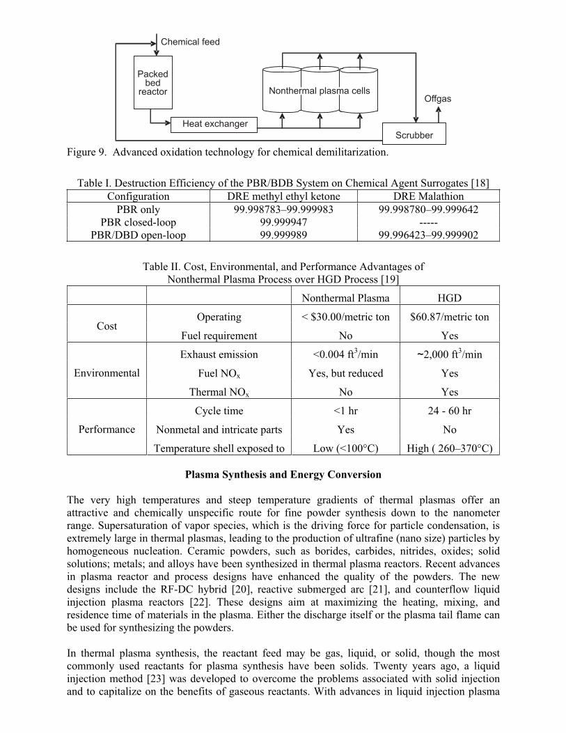
Safely demilitarizing the U.S. military’s large stockpiles of chemical warfare agents is a high priority for the U.S. Department of Defense. The nerve agents, GB (also called Sarin) and VX, are extremely toxic organophosphorous compounds. Rosocha [18] investigated applying the PBR/DBD technology to destroy these agents. The two-stage thermal packed-bed and nonthermal plasma waste treatment system (Figure 9) was tested with methyl ethyl ketone and Malathion as surrogates. The test results, shown in Table I, established the technical basis for applying the PBR/DBD to chemical warfare agents. Destruction of chemical warfare agents requires a DRE (destruction removal efficiency) of at least six 9s.
The U.S. Army sponsored a study to compare nonthermal plasma and hot gas decontamination (HGD) of chemical weapon shell surfaces [19]. The nonthermal plasma system destroyed up to 99.98% of 1.0 g TNT on an 8-mm shell in a one-step treatment. The treatment time is very short, about 10–15 minutes. A comparison between the plasma and HGD processes is shown in Table II. It is clear that nonthermal plasma outperforms the HGD process.
Scrubber
Heat exchanger
Packedbed
reactor
Chemical feed
Nonthermal plasma cellsOffgas
Figure 9. Advanced oxidation technology for chemical demilitarization.
Table I. Destruction Efficiency of the PBR/BDB System on Chemical Agent Surrogates [18]
Configuration DRE methyl ethyl ketone DRE Malathion
PBR only 99.998783–99.999983 99.998780–99.999642 PBR closed-loop 99.999947 -----
PBR/DBD open-loop 99.999989 99.996423–99.999902
Table II. Cost, Environmental, and Performance Advantages of Nonthermal Plasma Process over HGD Process [19]
Nonthermal Plasma HGD
Operating < $30.00/metric ton $60.87/metric ton Cost
Fuel requirement No Yes
Exhaust emission <0.004 ft3/min ~2,000 ft3/min
Fuel NOx Yes, but reduced Yes Environmental
Thermal NOx No Yes
Cycle time <1 hr 24 - 60 hr
Nonmetal and intricate parts Yes No Performance
Temperature shell exposed to Low (<100°C) High ( 260–370°C)
Plasma Synthesis and Energy Conversion
The very high temperatures and steep temperature gradients of thermal plasmas offer an attractive and chemically unspecific route for fine powder synthesis down to the nanometer range. Supersaturation of vapor species, which is the driving force for particle condensation, is extremely large in thermal plasmas, leading to the production of ultrafine (nano size) particles by homogeneous nucleation. Ceramic powders, such as borides, carbides, nitrides, oxides; solid solutions; metals; and alloys have been synthesized in thermal plasma reactors. Recent advances in plasma reactor and process designs have enhanced the quality of the powders. The new designs include the RF-DC hybrid [20], reactive submerged arc [21], and counterflow liquid injection plasma reactors [22]. These designs aim at maximizing the heating, mixing, and residence time of materials in the plasma. Either the discharge itself or the plasma tail flame can be used for synthesizing the powders.
In thermal plasma synthesis, the reactant feed may be gas, liquid, or solid, though the most commonly used reactants for plasma synthesis have been solids. Twenty years ago, a liquid injection method [23] was developed to overcome the problems associated with solid injection and to capitalize on the benefits of gaseous reactants. With advances in liquid injection plasma
synthesis, binary, ternary, quarternary, and higher component oxide solid solutions, including spinels of aluminates, ferrites, and chromites, and high temperature oxide superconductors, have been synthesized in plasmas [24,25]. Besides these exotic compounds, there has been little activity in oxide synthesis. However, there are strong and continuing efforts in the synthesis of nonoxide powders such as borides, carbides, and nitrides. The most common reactants for thermal plasma synthesis of nonoxides are solids and metal halides. Kong and Pfender [1] gave an in-depth review of plasma synthesis of nonoxide ceramic powders.
Currently, Idaho National Laboratory (INL) is developing new plasma processes and systems for nanoparticle synthesis and energy conversion. The plasma group at the INL developed a plasma fast quench process, PFQP, [26,27,28] to produce nanocrystalline metals, metal alloys, and ceramic powders, and to convert methane to high value products. The PFQP uses thermal plasma to dissociate the feed materials (gaseous and liquid) to their atomic constituents and form thermodynamically stable products in the 5–50-nm range. To produce uniformly-sized nanoparticles, the thermal plasma quench rates must be controllable. If the product nuclei are immediately fast quenched from high temperatures to low temperatures, the average size of the particles will be very small. Ultra-fast quenching also stops collision growth and sintering that would form particle aggregates into large particles. Ultra-fast quenching preserves and stabilizes the product powder mean size at ambient temperature.
The technology behind ultra-fast quenching is a converging-diverging nozzle (Figure 10). It induces supersonic flow and a tremendous pressure and temperature drop to freeze the reaction and preserve the composition and particle size of the reaction products. Using the basic principle of a converging-diverging nozzle, the INL invented and patented PFQP in the late 1990s. Since then, it has been used in a variety of applications. The nozzle-induced supersonic flow quenches the products from plasma temperature to ambient temperature in milliseconds. This super fast quenching leads to an extremely high rate of homogeneous gas phase nucleation of nanoparticles. Furthermore, super fast quenching terminates particle growth, thus preserving the nano size. Consequently, the quench nozzle produces powders with a narrow size distribution. Nanopowders of alumina and titania synthesized with the plasma fast quench reactor are shown in Figure 11. The average particle size is below 50 nm and the size distribution is narrow.
Quench nozzle
Plasma flow outPlasma flow in
Figure 10. INL plasma fast quench reactor.
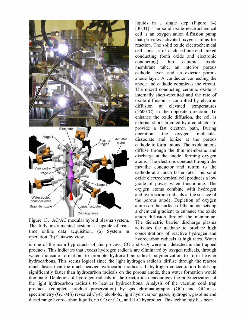
A large industry entered into a cooperative research agreement with INL to further develop the plasma quench technology for low cost production of paint pigment nanoparticles. The initial results were encouraging; several paint pigment nanoparticles had surface areas ranging from 196 to 218 m2/g. Coatings made with the nanopigment particles have a superior lifetime to those made with conventional pigment particles in ASTM B117 salt spray testing. Electron micrographs of one of these particles are shown in Figure 12. However, during technology development with the client company, several limitations of the plasma fast quench technology were identified: short residence time, small high temperature zone, small powder feed size, preference for high vapor pressure feed stocks (e.g. gas and liquid phase reactants), and high feed material cost. INL developed a modular AC/AC hybrid plasma concept [29] to address these issues (Figure 13). The modular AC/AC hybrid plasma reactor has a much longer residence time and a large high temperature reaction zone for melting and vaporizing the reactant feed. The
Figure 11. TEM micrographs of PFQP-synthesized alumina and titania nanoparticles.
Figure 12. TEM micrographs of PFQP-synthesized ternary oxide nanopigment particles.
system can accommodate feed materials with large particle sizes, upwards of 200 m. The system is robust, scalable, and has a versatile feed process. Material synthesized with this system is in the nano size range. Currently, the system is going through vigorous shake down tests, system and process optimization, and powder-processing characteristic assessments.
Besides thermal plasma synthesis of materials, INL also engages in nonthermal plasma technology research and development for energy conversion. Two important areas of research in the last decade are conversion of natural gas to a liquid and heavy hydrocarbon and natural gas co-conversion. These novel technologies are covered by several patents.
The patented technology for direct natural gas to liquid conversion combines a solid oxide electrochemical cell and dielectric barrier discharge plasma to convert natural gas to hydrocarbon
liquids in a single step (Figure 14) [30,31]. The solid oxide electrochemical cell is an oxygen anion diffusion pump that provides activated oxygen atoms for reaction. The solid oxide electrochemical cell consists of a closed-one-end mixed conducting (both oxide and electronic conducting) thin ceramic oxide membrane tube, an interior porous cathode layer, and an exterior porous anode layer. A conductor connecting the anode and cathode completes the circuit. The mixed conducting ceramic oxide is internally short-circuited and the rate of oxide diffusion is controlled by electron diffusion at elevated temperatures (>600°C) in the opposite direction. To enhance the oxide diffusion, the cell is external short-circuited by a conductor to provide a fast electron path. During operation, the oxygen molecules dissociate and ionize at the porous cathode to form anions. The oxide anions diffuse through the thin membrane and discharge at the anode, forming oxygen atoms. The electrons conduct through the metallic conductor and return to the cathode at a much faster rate. This solid oxide electrochemical cell produces a low grade of power when functioning. The oxygen atoms combine with hydrogen and hydrocarbon radicals at the surface of the porous anode. Depletion of oxygen atoms on the surface of the anode sets up a chemical gradient to enhance the oxide anion diffusion through the membrane. The dielectric barrier discharge plasma activates the methane to produce high concentrations of reactive hydrogen and hydrocarbon radicals at high rates. Water
is one of the main byproducts of this process; CO and CO2 were not detected in the trapped products. This indicates that excess hydrogen radicals are eliminated by oxygen radicals, through water molecule formation, to promote hydrocarbon radical polymerization to form heavier hydrocarbons. This seems logical since the light hydrogen radicals diffuse through the reactor much faster than the much heavier hydrocarbon radicals. If hydrogen concentration builds up significantly faster than hydrocarbon radicals on the porous anode, then water formation would dominate. Depletion of hydrogen radicals in the reactor also encourages the polymerization of the light hydrocarbon radicals to heavier hydrocarbons. Analysis of the vacuum cold trap products (complete product preservation) by gas chromatography (GC) and GC-mass spectrometry (GC-MS) revealed C1-C5 alcohols, light hydrocarbon gases, hydrogen, gasoline and diesel range hydrocarbon liquids, no CO or CO2, and H2O byproduct. This technology has been
Figure 13. AC/AC modular hybrid plasma system. The fully instrumented system is capable of real-time online data acquisition. (a) System in operation. (b) Cutaway view.
Methane inProduct out
HV AC power supply
Heater
Outer coil electrode
Inner electrode
Porousanode
O2-
diffusionmembrane tube
Air in
e-
Quartz tube
Porouscathode
Plasma
Figure 14. Solid oxide electrochemical/dielectric barrier discharge plasma reactor for natural gas to liquid conversion.
tested on a bench scale; significant research is needed to bring the technology to the next level of development.
The patented technology [32] for heavy hydrocarbon and natural gas co-conversion using nonthermal plasma at moderately elevated temperatures (<300°C) uses a dielectric barrier discharge plasma to activate methane to produce a high concentration of reactive light hydrocarbon and hydrogen radicals (Figure 15). At the same time, the heavy hydrocarbon is activated by the methane plasma. The light hydrocarbon radicals crack the heavy molecules into multiple lighter fragments. Hydrogen radicals collide with these fragments and terminate the reaction by attachment, thus forming lighter molecules. The results of process development studies that used cetane, a n-alkane with 16 carbons, as a model compound, were quite amazing. Over 30% of the cetane was converted to a range of light hydrocarbon liquids and gases in a single pass. The converted product contains normal olefins and aliphatics, branched compounds, and aromatics. No heavy hydrocarbons higher than the original material were founded in the
Outer electrode
HV AC power supply
Furnace insulation
Furnace power supply Reactants inProducts out
Methane plasma
Center electrode
HeatingelementLiquid film reaction
Figure 15. Nonthermal plasma co-conversion of natural gas and heavy hydrocarbons.
product. In another process development test, a refinery heavy stream, vacuum gas oil (VGO), was treated in the methane nonthermal plasma in a single pass. The results were just as encouraging as the model compound study. The heavy aliphatic and heavy aromatic compositions in the VGO were reduced and no compounds heavier than the original material were formed. The GC results of plasma treatment of cetane and VGO are shown in Figures 16 and 17. This technology has been tested on a bench scale; significant research is needed to bring the technology to the next level of development.
Figure 16. Products formed after a single-pass treatment of cetane in nonthermal plasma. 31% conversion was achieved with a very high yield of C6 compounds.
Figure 17. Products formed after a single-pass treatment of VGO in nonthermal plasma.
Summary
Thermal plasmas have found increasing applications in waste destruction, material recovery, extractive metallurgy, powder synthesis, coating deposition, and energy conversion. Plasma treatment of automotive exhausts has been the main thrust of nonthermal plasma research and development, though limited research has been performed on using nonthermal plasmas for demilitarization, other waste treatment, energy conversion, and material synthesis. A brief discussion of recent plasma technology research and development activities at the Idaho National Laboratory is included.
Acknowledgements
Work supported by the U.S. Department of Energy, Assistant Secretary for Environmental Management, under DOE Idaho Operations Office Contract DE-AC07-05ID14517.
References
1. P.C. Kong and E. Pfender, “Plasma Processes,” in Carbide, Nitride and Boride Materials-Synthesis and Processing, 1st edition, ed., A. W. Weimer (Chapman & Hall, 1997), 359-383.
2. C. Polprasert and L.R.J. Liyanage, “Hazardous Waste Generation and Processing,” Resource, Conservation and Recycling, 16 (1996) 213-226.
3. T.L. Eddy et al., “Thermal Processing System Concepts and Considerations for RWMC Buried Waste,” (Report EGG-WTD-10058, Idaho National Engineering Laboratory, 1992).
4. E. Daskalopoulos, O. Badr, and S.D. Probert, “Economic and Environmental Evaluation of Waste Treatment and Disposal Technologies for Municipal Solid Waste,” Applied Energy, 58 (4) (1997), 209-255.
5. J.V.R. Heberlein, “Thermal Plasma for the Destruction of Hazardous Wastes,” Proceedings of Plasma Technologies for Hazardous Waste Destruction, 37 (1993) 59-74.
6. M. Sakano, M. Tanaka, and T. Watanabe, “Application of Radio-Frequency Plasmas to Treatment of Fly Ash,” Thin Solid Film, 386 (2001) 189-194.
7. R. Burkhard, W. Hoffelner, and R.C. Eschenhach, “Recycling of Metal Waste with Thermal Plasma,” Resource, Conservation and Recycling, 10 (1994) 11-16.
8. R.C. Eschenhach, “Plasma Arc System for Waste Treatment and Metal Recovery,” JOM,(1996) 49-52.
9. J.W. Sears, R.C. Eschenhach, and R.A. Hill, “The Plasma Centrifugal Furnace: A Method for Stabilization and Decomposition of Toxic and Radioactive Wastes,” Waste Management, 10 (1990)165.
10. T.G. Barton, “Problem Waste Disposal by Plasma Heating,” International Recycling Congress, (Berlin, I, 1979) 733-736.
12. P. Taylor and W. Wang, “A Laboratory Investigation of the Reduction of Chromium Oxide by a Reverse-Polarity DC Plasma Driven Molten Oxide Electrolysis Process,” Plasma Chemistry And Plasma Processing, 22, (3) (2002) 387-400.
13. P. Taylor and S. Pirzada, “Plasma Technology in Extractive and Process Metallurgy,” Mineral Processing and Extractive Metallurgy Review, 12 (1995) 257-269.
14. L. Tang and H. Huang, “Thermal Plasma Pyrolysis of Used Tires for Carbon Black Recovery,” Journal of Materials Science, 40 (2005) 3817-3819.
15. T. Hammer, “Nonthermal Plasma Application to the Abatement of Noxious Emissions in Automotive Exhaust Gases,” Plasma Sources Sci. Technol., 11 (2002) A-196-A-201.
16. J. Chae, “Nonthermal Plasma for Diesel Exhaust Treatment,” Journal of Electrostatics, 57 (2003) 251-262.
17. L. Rosocha et al., “Two-Stage Thermal/Nonthermal Waste Treatment Process,” (Report LA-UR-93-1583, Los Alamos National Laboratory, 1993).
18. L. Rosocha et al., “Advanced Oxidation Technologies for Chemical Demilitarization,” (Report LA-UR-96-3948, Los Alamos National Laboratory, 1996).
19. B. Jang et al., “Comprehensive Evaluation of Catalytic Hydroreduction and Nonthermal Plasma as Alternative Technologies for Detoxification of Chemical Wastes,” NTIS AD-A395435 (2001).
20. T. Yoshida, “The Future of Thermal Plasma Processing,” Materials Transactions, JIM, 30 (1) (1990) 1-11.
21. A. Kumar and R. Roy, J. Mater. Res., 3, (1989) 1373.
22. P. C. Kong and E. Pfender, “Plasma Synthesis of Fine Powders by Counterflow Liquid Injection,” Combustion and Plasma Synthesis of High Temperature Materials, ed. Z.A. Munir and J.B. Holt, (1990) 420.
23. P. C. Kong and E. Pfender, “Synthesis of Ceramic Powders in a Thermal DC-Plasma Jet by Injection of Liquid Precursors,” (invited lecture, Proceedings of the 2nd Int. Conf. on Cerm. Powder Processing Sci., Berchtesgaden, FRG, 1988).
24. P. Kong and Y. Lau, “Plasma Synthesis of Ceramic Powders,” J. Pure and App. Chem., 62, (9) (1990) 1809.
25. P. Kong and E. Pfender, “Thermal Plasma Synthesis of Ceramics - A Review,” HeatTransfer in Thermal Plasma Processing, ed. K. Etemadi and J. Mostaghimi, ASME HTD-161, (1991) 1.
26. B. Detering et al., “Plasma Fast Quench Reactor and Method,” U.S. Patent 5,749,937 (1998).
27. B. Detering et al., “Plasma Fast Quench Reactor and Method,” U.S. Patent 5,935,293 (continuation in part) (1999).
28. B. Detering et al. “Plasma Fast Quench Reactor and Method,” U.S. Patent RE37853E, (2002).
29. P. Kong, P. Pink, and J. Lee, “Plasma Generators, Reactor Systems and Related Methods,” patent issuance fees paid December 2005.
30. P. Kong and P. Lessing, “Methods and Apparatus for Producing Oxygenates from Hydrocarbons,” U.S. Patent 5,427,747 (1995).
31. P. Kong and P. Lessing, “Method for Direct Conversion of Gaseous Hydrocarbons to Liquids,” U.S. Patent 7008970 (2006).
32. P. Kong, L. Nelson, and B. Detering, “Non-Thermal Plasma Systems and Methods for Natural Gas and Heavy Hydrocarbon Co-Conversion,” U.S. Patent 6896854 (2005).