Form 859-030604 SOLID-STATE RELAYS DATA SHEET page 1/14 Opto 22 • 43044 Business Park Drive • Temecula, CA 92590 • Phone: (909)695-3000 • (800)321-OPTO • Fax: (909)695-3095 • Internet: www.opto22.com Inside Sales: (800)452-OPTO • Product Support: (800)TEK-OPTO • (909)695-3080 • Fax: (909)695-3017 • E-mail: [email protected] • FaxBack: (800)474-OPTO In 1974, Opto 22 introduced the first liquid epoxy-filled line of power solid-state relays (SSR). This innovation in SSR design greatly improved the reliability and reduced the cost of manufacturing. At that time, we also incorporated into our manufacturing process 100% testing of every relay produced under full load conditions. By 1978, Opto 22 had gained such I n d e x Power Series P Series MP Series Z Series Overview a reputation for reliability that we were recognized as the world’s leading manufacturer of solid-state relays. Through continuous manufacturing improvements and the same 100% testing policy established 22 years ago, Opto 22 is still recognized today for the very high quality and reliability of its complete line of solid-state relays. Description Page Introduction 1 All Models: General Specifications 2 120/240 Volt AC Power Series: General Specifications 3 120/240 Volt AC Power Series: Surge Current Data, Thermal Data, and Dimensions 4 480/575 Volt AC Power Series: General Specifications 5 120/240 Volt AC Power Series Plastic Package (Z Series): General Specifications 6 AC Power Printed Circuit Series: General Specifications 7 DC Switching Series: General Specifications 9 APPLICATION TIPS Heat Sink Calculation, Duty Cycle Calculation 10 Transformer Loads, Solenoid Loads, and Lamp Loads 11 Solid-State Relays in Series, Lamp Loads, Heater Loads 12 Motor Loads 13
Transcript
Form 859-030604
SOLID-STATE RELAYS
DATA SHEET page 1/14
Opto 22 • 43044 Business Park Drive • Temecula, CA 92590 • Phone: (909)695-3000 • (800)321-OPTO • Fax: (909)695-3095 • Internet: www.opto22.com
In 1974, Opto 22 introduced the first liquid epoxy-filledline of power solid-state relays (SSR). This innovation in SSRdesign greatly improved the reliability and reduced the costof manufacturing. At that time, we also incorporated into ourmanufacturing process 100% testing of every relay producedunder full load conditions. By 1978, Opto 22 had gained such
I n d e x
Power Series
P Series MP Series
Z Series
Overview
a reputation for reliability that we were recognized as the world’sleading manufacturer of solid-state relays. Through continuousmanufacturing improvements and the same 100% testing policyestablished 22 years ago, Opto 22 is still recognized today for thevery high quality and reliability of its complete line of solid-staterelays.
Description Page
Introduction 1
All Models: General Specifications 2
120/240 Volt AC Power Series: GeneralSpecifications
3
120/240 Volt AC Power Series: Surge CurrentData, Thermal Data, and Dimensions
4
480/575 Volt AC Power Series: GeneralSpecifications
5
120/240 Volt AC Power Series Plastic Package(Z Series): General Specifications
6
AC Power Printed Circuit Series: GeneralSpecifications
7
DC Switching Series: General Specifications 9
APPLICATION TIPS
Heat Sink Calculation, Duty Cycle Calculation 10
Transformer Loads, Solenoid Loads, andLamp Loads
11
Solid-State Relays in Series, Lamp Loads,Heater Loads
12
Motor Loads 13
Form 859-030604
SOLID-STATE RELAYS
DATA SHEET page 2/14
Opto 22 • 43044 Business Park Drive • Temecula, CA 92590 • Phone: (909)695-3000 • (800)321-OPTO • Fax: (909)695-3095 • Internet: www.opto22.com
• Operating frequency: 25 to 65 Hz(operates at 400 Hz with six times off-state leakage)
• Coupling capacitance input to output: 8 pF maximum
All Models
Specifications
• DV/DT Off-state: 200 volts per microsecond
• DV/DT commutating: snubbed for rated currentat 0.5 power factor
• UL recognized
• CSA certified
• CE component
• See Opto 22 form #986 for torque specifications.
Optional plastic safety cover installed
on a Power Series SSR
A plastic safety cover (Opto 22 part number SAFETY COVER)is optionally available for Opto 22 Power Series SSRs. The safetycover reduces the chance of accidental contact with relayterminals, while providing access holes for test instrumentation.
Safety Cover for Power Series SSRs
Form 859-030604
SOLID-STATE RELAYS
DATA SHEET page 3/14
Opto 22 • 43044 Business Park Drive • Temecula, CA 92590 • Phone: (909)695-3000 • (800)321-OPTO • Fax: (909)695-3095 • Internet: www.opto22.com
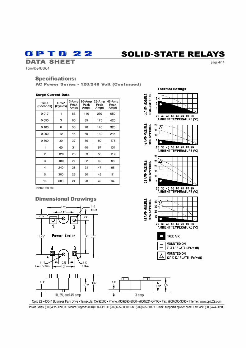
Opto 22 provides a full range of power series relays with a wide variety of voltage(110–575) and current options (3–45 amps). All Power Series relays feature 4,000 volts ofoptical isolation and have a high PRV rating.
Notes: qjc* = Thermal resistance junction to base. Maximum junction temperature is 110°C.** Operating Frequency: 25 to 65 Hz (operates at 400 Hz with 6 times the offstate leakage)
Form 859-030604
SOLID-STATE RELAYS
DATA SHEET page 4/14
Opto 22 • 43044 Business Park Drive • Temecula, CA 92590 • Phone: (909)695-3000 • (800)321-OPTO • Fax: (909)695-3095 • Internet: www.opto22.com
DC SERIES: The DC Series delivers isolated DC control to large OEM customers worldwide.AC SERIES: The AC Series offers the ultimate in solid-state reliability. All AC power series
relays feature a built-in snubber and zero voltage turn-on. Transient proof models offer self-protection for noisy electrical environments.
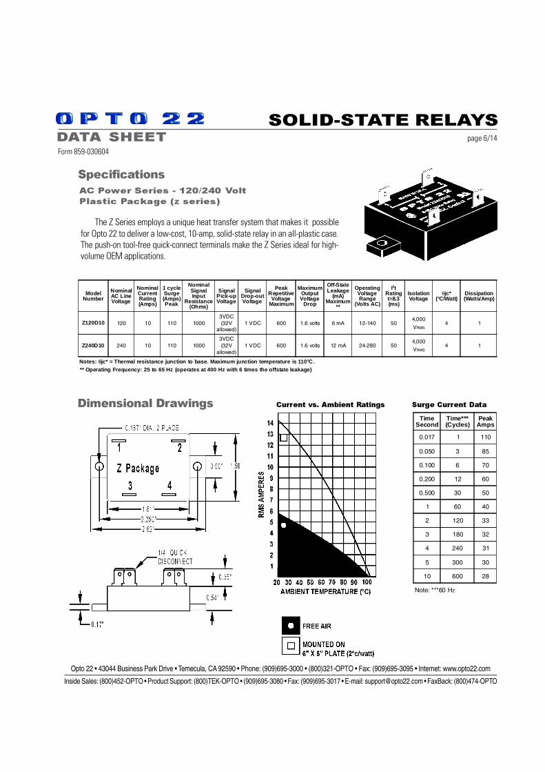
The Z Series employs a unique heat transfer system that makes it possiblefor Opto 22 to deliver a low-cost, 10-amp, solid-state relay in an all-plastic case.The push-on tool-free quick-connect terminals make the Z Series ideal for high-volume OEM applications.
Dimensional Drawings
AC Power Series - 120/240 Volt
Plastic Package (z series)
Specifications
ModelNumber
NominalAC LineVoltage
NominalCurrentRating(Amps)
1 cycleSurge(Amps)Peak
NominalSignalInput
Resistance(Ohms)
SignalPick-upVoltage
SignalDrop-outVoltage
PeakRepetitive
VoltageMaximum
MaximumOutputVoltage
Drop
Off-StateLeakage
(mA)Maximum
**
OperatingVoltageRange
(Volts AC)
I2tRatingt=8.3(ms)
IsolationVoltage
θjc*(°C/Watt)
Dissipation(Watts/Amp)
Z120D10 120 10 110 10003VDC(32V
allowed)1 VDC 600 1.6 volts 6 mA 12-140 50
4,000
VRMS4 1
Z240D10 240 10 110 10003VDC(32V
allowed)1 VDC 600 1.6 volts 12 mA 24-280 50
4,000
VRMS4 1
Notes: θjc* = Thermal resistance junction to base. Maximum junction temperature is 110°C.** Operating Frequency: 25 to 65 Hz (operates at 400 Hz with 6 times the offstate leakage)
TimeSecond
Time***(Cycles)
PeakAmps
0.017 1 110
0.050 3 85
0.100 6 70
0.200 12 60
0.500 30 50
1 60 40
2 120 33
3 180 32
4 240 31
5 300 30
10 600 28
Note: ***60 HZ
Form 859-030604
SOLID-STATE RELAYS
DATA SHEET page 7/14
Opto 22 • 43044 Business Park Drive • Temecula, CA 92590 • Phone: (909)695-3000 • (800)321-OPTO • Fax: (909)695-3095 • Internet: www.opto22.com
Like all semiconductor devices, SSR current ratingsmust be based on maximum junction temperature.All Opto 22 SSRs operate conservatively at maximumjunction temperatures of 110° C. Determining anadequate heat sink for a given SSR conducting agiven current is very simple.
Note: Thermally conductive grease must be usedbetween the relay base and the heat sink.
Sample Calculation Given:
120-Volt, 20-Amp Load50° C Ambient Air
Choose Model 120D25 SSR.
Calculate dissipation as: 20 amps x 1.3 Watts per amp = 26 Watts
Calculate temperature rise junction to SSR base as: 26 Watts x 1.2° C per Watt = 31.2° C
Calculate allowable temperature of heat sink by subtracting 31.2° C from 110° C allowable junction temperature:
110° C-31.2 = 78.8° C
The heat sink is in a 50°C ambient, therefore, allowable temperature rise on heat sink is: 78.8° C-50° C = 28.8° C
If heat sink is allowed to rise 28.8° C above ambient, then the thermal resistance of the heat sink is simply the 28.8° C rise divided bythe 26 Watt. Any heat sink having a thermal resistance less than 1.1° C per Watt will be adequate.
Duty Cycle Calculation
When solid-state relays are operated in an on/off mode, it may be advantageous to calculate the RMS value of the current through theSSR for heat sinking or determining the proper current rating of the SSR for the given application.
IRMS
= RMS value of load or SSRT
1 = Time current is on
T2 = Time current is off
ION
= RMS value of load current during on period
IRMS = (ION)2
x T1
T1 + T2
Tips
Applications
Form 859-030604
SOLID-STATE RELAYS
DATA SHEET page 11/14
Opto 22 • 43044 Business Park Drive • Temecula, CA 92590 • Phone: (909)695-3000 • (800)321-OPTO • Fax: (909)695-3095 • Internet: www.opto22.com
Transformer Loads Solenoid Valve and Contactor Loads
Careful consideration should be given to the selectionof the proper SSR for driving a given transformer. Transformersare driven from positive saturation of the iron core to negativesaturation of the core each ½ cycle of the alternating voltage.Large inrush currents can occur during the first ½ cycle of linevoltage when a zero voltage SSR happens to turn on duringthe positive ½ cycle of voltage when the core is already inpositive saturation. Inrush currents greater than 10 times ratedtransformer current can easily occur. The following tableprovides a guide for selecting the proper SSR for a giventransformer rating.
All Opto 22 SSRs are designed to drive inductive loads such as solenoidvalves and electromechanical contactors. The built-in snubber in eachSSR assures proper operation into inductive loads. The following tableis a guide in selecting an SSR to drive a solenoid or contactor.
Tips (Continued)
Applications
Control Current Calculation
All Opto 22 DC controlled SSRs have a control circuit consisting of 1000 ohms inseries with an LED. Since 3 volts is required to turn on any SSR, the maximum currentrequired is (3 volt - 1 volt) divided by 1000 ohms which equals 2.0 mA. The 1 volt issubtracted from the 3 volt signal because 1 volt is dropped across the LED. For highercontrol voltages, an external resistor can be added in series with the control voltage tolimit the control current. To limit the control current to 2 mA, calculate the external resistorRC = 500 (EC- 3) where EC = the control voltage.
The DC control voltage range is 3–32 VDC. To calculate the control current for any voltagewithin the 3–32 VDC range, use the formula:
EC - 1
1000IC =
where RC = zero.
With a 5V control signal,
IC = = 4 mA.5 - 1
1000
120-Volt Coils
SSR CURRENTRATING SOLENOID CONTACTOR
2-Amp 1-Amp NEMA Size 4
4-Amp 3-Amp NEMA Size 7
240-Volt Coils
SSR CURRENTRATING SOLENOID CONTACTOR
2-Amp 1-Amp NEMA Size 7
4-Amp 3-Amp NEMA Size 7
120-Volt Transformers
SSR MODEL TRANSFORMER
P or MP 120D2 100 VA
Z120D10 500 VA
120D3 100 VA
P or MP 120D4 250 VA
120D10 or 120A10 500 VA
120D25 or 120A25 1 KVA
120D45 2 KVA
240-Volt Transformers
P or MP240D2 200 VA
7240D10 1 KVA
120D3 200 VA
P or MP240D4 500 VA
240D10 or 240A10 1 KVA
240D25 or 240A25 2 KVA
240D45 4 KVA
480-Volt Transformers
SSR MODEL TRANSFORMER
480D10-12 5-Amp Primary
480D15-12 5-Amp Primary
Form 859-030604
SOLID-STATE RELAYS
DATA SHEET page 12/14
Opto 22 • 43044 Business Park Drive • Temecula, CA 92590 • Phone: (909)695-3000 • (800)321-OPTO • Fax: (909)695-3095 • Internet: www.opto22.com
In applications requiring greater current rating at higher voltage,two Opto 22 SSRs may be operated in series for double thevoltage rating. The built-in snubber in each SSR assures propervoltage sharing of the two SSRs in series. In the diagram below,two 240-volt, 45-amp SSRs are connected in series for operationon a 480-volt line. The control is shown with a parallel hook-upbut it should be noted that a serial connection can also beimplemented.
Lamp Loads
Since all Opto 22 SSRs are zero voltage switching,they are ideal for driving incandescent lamps becausethe initial inrush current into a cold filament isreduced. The life of the lamp is increased whenswitched by a zero voltage turn on SSR. The followingtable is a guide to selecting an Opto 22SSR for switching a given incandescent lamp.
Heater Loads
Care should be taken in selecting a SSR for driving a heater load ifthe load is cycled on and off in a continuous manner as might occurin a temperature control application. Constant cycling can causethermal fatigue in the thyristor chip at the point where the chipbonds to the lead frame. Opto 22 employs a thick copper lead framefor mounting the SCR chips in the power series SSRs to eliminatethermal fatigue failures. In addition, Opto 22 recommends operatingany SSR at 75% rated current for cycling heater loads to ensurecomplete reliability.
The following table is a guide to selecting the proper SSR for agiven heater load.
Three-Phase Motor Control Three-Phase Reversing Motor Control
Three-phase motors maybe controlled by solid-staterelays as shown. A thirdSSR as shown is optional,but not necessary. Thecontrol windings may beconnected in series orparallel. Care should betaken to ensure that surgecurrent drawn by the motordoes not exceed surgecurrent rating of the SSR.
Three-phase reversing motor control can be implemented with fourSSRs as shown in the connection diagram. The SSRs work in pairswith SSR1 and SSR3 operated for rotation in one direction and SSR2and SSR4 operated for rotation in the reverse direction. The resistorR1 as shown in the connection diagram protects against line-to-lineshorts if SSR1 and SSR4 or SSR3 and SSR2 are on at the same timeduring the reversing transition period. Use the following table as aguide to the proper selection of an SSR for this application.
The resistors are unnecessary if thecontrol circuit is designed to ensureone SSR is off before the other SSRis on.
The circuit diagram illustrates a typical 1 Ø motor winding inductance and the phase shiftcapacitor can cause twice line voltage to appear across the open SSR. A 240-volt SSR shouldbe used for a 120-Volt line. During the transition period when one SSR is turned on and theother SSR is going off, both SSRs may be on. In this case, the capacitor may discharge throughthe two SSRs, causing large currents to flow, which may destroy the SSRs. The addition of RLas shown will protect the SSRs from the short circuit capacitor discharge current.
CALCULATE RL as: RL =
EXAMPLE: 10 amp SSR120 V AC Line
RL = = 1.7 ohm
240-Volt 3q Motors
SSR MODEL MOTOR
Z240D25 1/3 HP
Z240D10 3/4 HP
240D10 3/4 HP
240A10 3/4 HP
240D25 2 HP
240A25 2 HP
240D45 3 HP
480-Volt 3q Motors
SSR MODEL MOTOR
480D10-12 1-½ HP
480D15-12 1-½ HP
Opto 22Relay
Motor FullLoad Rating
Resistor for120V line
Resistor for240V line
3-Amp 1.25-Amp 4 ohm 50 W 8 ohm 50 W
10-Amp 5-Amp 1 ohm 100 W 2 ohm 100 W
25-Amp 8-Amp .5 ohm 100 W 1 ohm 100 W
45-Amp 16-Amp .25 ohm 150 W .5 ohm 150 W
15-Amp 5-Amp 1 ohm 100 W 2 ohm 100 W
Form 859-030604
SOLID-STATE RELAYS
DATA SHEET page 14/14
Opto 22 • 43044 Business Park Drive • Temecula, CA 92590 • Phone: (909)695-3000 • (800)321-OPTO • Fax: (909)695-3095 • Internet: www.opto22.com
ProductsOpto 22 produces a broad array of reliable, flexible hardwareand software for industrial automation and remote monitoring.Opto 22’s diverse and complete product range allows you tobuy in at any level, from solid-state relays to fully integratedcontrol systems.
SNAP Ultimate I/O™The most intelligent and powerful I/O system available,SNAP Ultimate I/O effectively combines I/O, control,
networking, and enterpriseconnectivity into a single cohesivesystem. SNAP Ultimate I/O hasthe ability to communicate directly
with enterprise systems, eliminatingthe need for complex middleware and the significant
investments associated with it. Software and utilitiesfor use with SNAP Ultimate I/O include ioControl™flowchart-based control programming software andioDisplay™, a Windows-based HMI development package.
SNAP Ethernet I/O™Using SNAP Ethernet I/O systems, you can connect a wide
variety of electronic and mechanical devicessuch as lights, temperature and pressuresensors, motors, and serial devices to
computers via a standard Ethernetnetwork, wireless LAN, or even the Internet.
SNAP-IT™ Systems
A packaged solution that brings industry-provenSNAP Ethernet technology to your enterprise
faster and easier than ever before, SNAP-ITis a network-ready hardware appliance that
connects environmental, device,and other sensors directly to yourenterprise applications. The connected
devices can then be controlled and real-time operational datacan be collected, monitored, and delivered via a standardEthernet, wireless LAN, or dial-up network.
Opto 22 FactoryFloor™ SoftwareFactoryFloor is an integrated suite ofindustrial control software applicationsdesigned to help you develop controlautomation solutions, build easy-to-useoperator interfaces, and expand yourmanufacturing systems’ connectivity.
Other Software and HardwareSoftware developer kits (SDKs), diagnosticutilities, support for the Linux operatingsystem, and a full line of SNAP industrialcontrollers are also available from Opto 22.
QualityIn delivering hardware and software solutions for worldwidedevice management and control, Opto 22 retains the highestcommitment to quality.
We do no statistical testing; each product is made in theU.S.A. and is tested twice before leaving our 160,000 square-foot manufacturing facility in Temecula, California. That’s whywe can guarantee solid-state relays and all optically-isolatedI/O modules for life.
Product SupportOpto 22’s Product Support Group offers comprehensivetechnical support for Opto 22 products. The staff of supportengineers represents years of training and experience, andcan assist with a variety of project implementation questions.Product support is available in English and Spanish fromMonday through Friday, 8 a.m. to 5 p.m. Pacific Standard Time.
Opto 22 Web Siteswww.opto22.comwww.m2m.opto22.comwww.internetio.com (live Internet I/O demo)www.ultimateio.com (SNAP Ultimate I/O information)
Other Resources• OptoInfo CDs • Ongoing, up-to-date training• Integration support • FaxBack service: (800) 474-OPTO
About Opto 22Founded in 1974, Opto 22 is a leading manufacturer
of high-quality hardware and softwaresolutions for connecting real-worlddevices with computer networks.Customer applications includeenterprise management, remote
monitoring and control, industrial automation, and dataacquisition. Opto 22 was one of the first companies torecognize and implement solutions involving networks,computers, and real-world equipment and devices. Morethan 75 million devices worldwide are reliably connectedto Opto 22 systems.