14
NEW ENERGY SOLUTIONS SOLUTIONS FOR E-MOBILITY DEMANDS
NEW ENERGY SOLUTIONS
SOLUTIONS FOR
E-MOBILITY DEMANDS
p a g e | 2
TABLE OF CONTENTS Page
1 Introduction 3
2 E-mobility charging – IEC61851 modes and SAE J1772 levels 3
3 ZETTLER Relays and Contactors 7
3.1 ZETTLER Relays for SAE AC level 1 charging 7
3.2 ZETTLER Relays for SAE AC level 2 and IEC mode 2 – Generation 1 charging 7
3.3 ZETTLER AC circuit Relays for IEC mode 2 – Generation 2 charging 9
3.4 ZETTLER Contactors for SAE AC level 2 and IEC mode 3 charging 11
4 ZETTLER Magnetics – Current Sense Transformers 12
5 AZ Displays – a member of the ZETTLER Group 13
6 ZETTLER Contacts 14
p a g e | 3
Copyright ZETTLER Group 2016
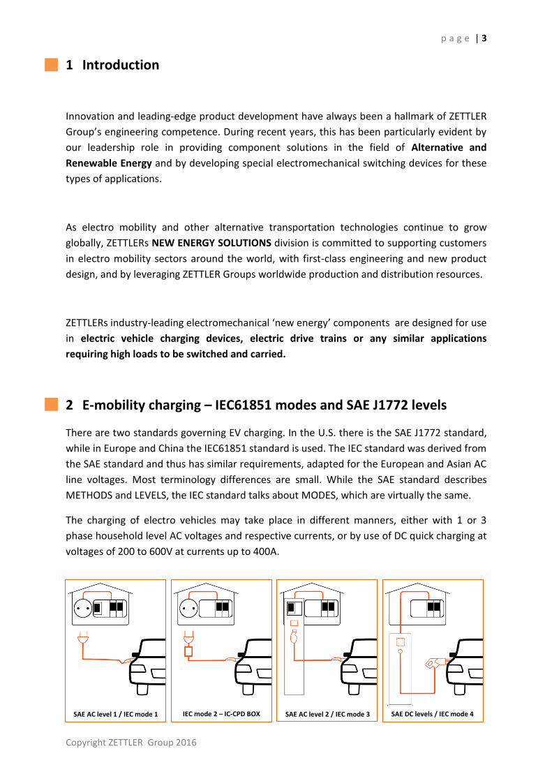
SAE DC levels / IEC mode 4 SAE AC level 2 / IEC mode 3 IEC mode 2 – IC-CPD BOX SAE AC level 1 / IEC mode 1
1 Introduction
Innovation and leading-edge product development have always been a hallmark of ZETTLER
Group’s engineering competence. During recent years, this has been particularly evident by
our leadership role in providing component solutions in the field of Alternative and
Renewable Energy and by developing special electromechanical switching devices for these
types of applications.
As electro mobility and other alternative transportation technologies continue to grow
globally, ZETTLERs NEW ENERGY SOLUTIONS division is committed to supporting customers
in electro mobility sectors around the world, with first-class engineering and new product
design, and by leveraging ZETTLER Groups worldwide production and distribution resources.
ZETTLERs industry-leading electromechanical ‘new energy’ components are designed for use
in electric vehicle charging devices, electric drive trains or any similar applications
requiring high loads to be switched and carried.
2 E-mobility charging – IEC61851 modes and SAE J1772 levels
There are two standards governing EV charging. In the U.S. there is the SAE J1772 standard,
while in Europe and China the IEC61851 standard is used. The IEC standard was derived from
the SAE standard and thus has similar requirements, adapted for the European and Asian AC
line voltages. Most terminology differences are small. While the SAE standard describes
METHODS and LEVELS, the IEC standard talks about MODES, which are virtually the same.
The charging of electro vehicles may take place in different manners, either with 1 or 3
phase household level AC voltages and respective currents, or by use of DC quick charging at
voltages of 200 to 600V at currents up to 400A.

p a g e | 4
SAE AC level 1: Level 1 Charging utilizes a direct cable connection between the EV and a
standard 1 phase 120V AC wall outlet. The outlet has to be protected by a circuit breaker
and ground fault interrupter (GFI)/residual current detector (RCD). Charging power of 1.9
kW can be achieved.
SAE AC level 2: This is charging with 1 or 3 phase AC by use of a stationary charging station
which is protected by a circuit breaker and GFI/RCD. The charging station and the vehicle
communicate to each other to control the charging process. With a peak current of 80A, the
maximum delivered power can be nearly up to 20kW. The SAE’s level 2 is comparable to the
IEC’s mode 3.
SAE DC levels: SAE J1772 also defines charging at DC voltages with high currents of some 100
amperes and voltages up to 400V and above. Due to the high amount of electrical power, DC
charging allows minimizing charging time and is generally referred to as DC quick charging.
IEC mode 1: Similar to SAE AC level 1 charging, this is charging with AC on a typical
household wall outlet, either 1 or 3 phase with currents up to 16A. In this mode there is no
communication between the energy source/grid and the vehicle. It must be ensured that
some GFI/RCD protective device is installed on the infrastructure side.
IEC mode 2: The difference to mode 1 is basically that there are higher currents and a
control and protection equipment integrated into the charger cable (In-Cable Control and
Protection Device – IC-CPD). The IC-CPD protects from electrical hazards in case of isolation
failures and is defined in IEC62752. In its newest edition the IEC62752:2016 requires a peak
current Ip of up to 1.5kA in case of short circuits. ZETTLERs newest developments are tailored
to fulfil this challenging demand
IEC mode 3: In this mode charging with AC takes place through a dedicated charging outlet
which is connected to a stationary charger (or wallbox). Charging is controlled via
communication between charging unit and the vehicle. IEC mode 3 charging is based on a
special purpose infrastructure to deliver the necessary power.
IEC mode 4: This is charging similar to the SAE’s DC levels. Charging with DC is useful when
charging with a high amount of power. In IEC mode 4 there is a dedicated wallbox with fixed
charging cable and a dedicated DC charging plug.

p a g e | 5
Copyright ZETTLER Group 2016
The ‘ZETTLER Advantage’
As electro vehicles will have a significant impact in future personal mobility and public
transportation, we have continually expanded our line of relays and contactors. These state-
of-the-art ZETTLER components have been successfully integrated by manufacturers of
charging equipment.
Charging modes Switching Sensing Visualizing
IEC mode 1 SAE AC level 1 Direct Connection
Not applicable Not applicable Not applicable
IEC mode 2 IC-CPD BOX
Available - and new products under development
Available by ZETTLER
Available by ZETTLER
IEC mode 3 SAE AC level 2 Stationary AC Charger
Available by ZETTLER
Available by ZETTLER
Available by ZETTLER
IEC mode 4 SAE DC levels Stationary DC Charger
Intended
Available by ZETTLER
Available by ZETTLER
Today, ZETTLER’s product line of AC circuit Relays and Contactors spans across an extended
range of product characteristics which make them suitable for many demands in EV
charging. These products are accompanied by AC current sensing transformers and HMI
solutions of our AZ Displays subsidiary.
SA
E A
C LE
VE
L 2
Sta
tion
ary
AC
Charg
er
IEC MODE 2
IC-CPD BOX
IEC62752
SWITCHING
AZSR235/250/180
AZSR116/132/140
XMC0 series contactors
SENSING
ACST series AC current sensing
transformers
VISUALIZING
AZ Displays LCD solutions
IEC MODE 3
Stationary AC Charger

p a g e | 6
Withstand highest momentary currents with special contact arrangements
In the AZSR116/132/140 series the conventional contact spring arrangement is replaced by a
patent pending1) solution to survive highest momentary currents, as they may occur on short
circuits. Through this special arrangement the contact performance even increases due to
magnetic force; thus ensuring an outstanding reliability without contact welding.
On the AZSR140 this approach allows 40 Amp switching current and an up to 1500 Amp of
short circuit current (carrying) without welding. With its low holding power of only 200mW
(also suitable for PWM), this PCB relay has entered a dimension that was hardly imaginable
just a few years ago.
Fulfilling safety and supervisory demands with contact monitoring
Additionally the AZSR116/132/140 features a potential free N.C. (1 Form B) monitoring
supervisory contact as required by IEC62752:2016, thus making these types of relays ideally
suited for applications with high security and safety demands. Contact welding or
malfunction can thus be easily detected and indicated.
1) German patent application pending (DE10 2014 106 957.9)
Figure 1: AZSR116/132/140 contact system
p a g e | 7
Copyright ZETTLER Group 2016
3 ZETTLER Relays and Contactors
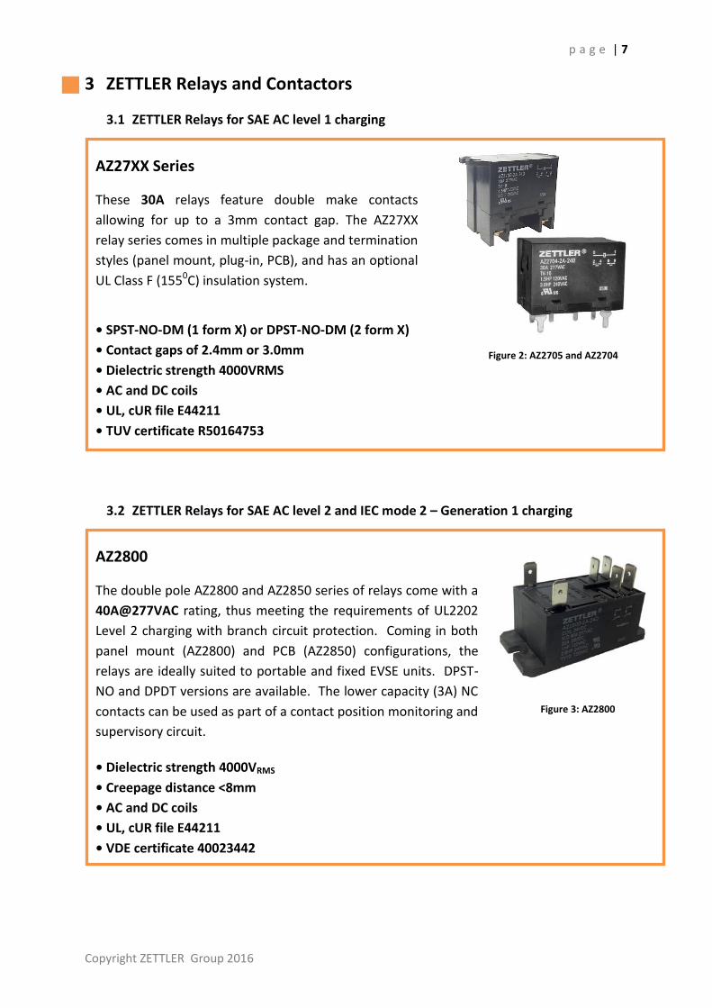
3.1 ZETTLER Relays for SAE AC level 1 charging
3.2 ZETTLER Relays for SAE AC level 2 and IEC mode 2 – Generation 1 charging
Figure 2: AZ2705 and AZ2704
AZ27XX Series
These 30A relays feature double make contacts
allowing for up to a 3mm contact gap. The AZ27XX
relay series comes in multiple package and termination
styles (panel mount, plug-in, PCB), and has an optional
UL Class F (1550C) insulation system.
• SPST-NO-DM (1 form X) or DPST-NO-DM (2 form X)
• Contact gaps of 2.4mm or 3.0mm
• Dielectric strength 4000VRMS
• AC and DC coils
• UL, cUR file E44211
• TUV certificate R50164753
Figure 3: AZ2800
AZ2800
The double pole AZ2800 and AZ2850 series of relays come with a
40A@277VAC rating, thus meeting the requirements of UL2202
Level 2 charging with branch circuit protection. Coming in both
panel mount (AZ2800) and PCB (AZ2850) configurations, the
relays are ideally suited to portable and fixed EVSE units. DPST-
NO and DPDT versions are available. The lower capacity (3A) NC
contacts can be used as part of a contact position monitoring and
supervisory circuit.
• Dielectric strength 4000VRMS
• Creepage distance <8mm
• AC and DC coils
• UL, cUR file E44211
• VDE certificate 40023442
p a g e | 8
2) International patent application pending (PCT/EP2015/076187)
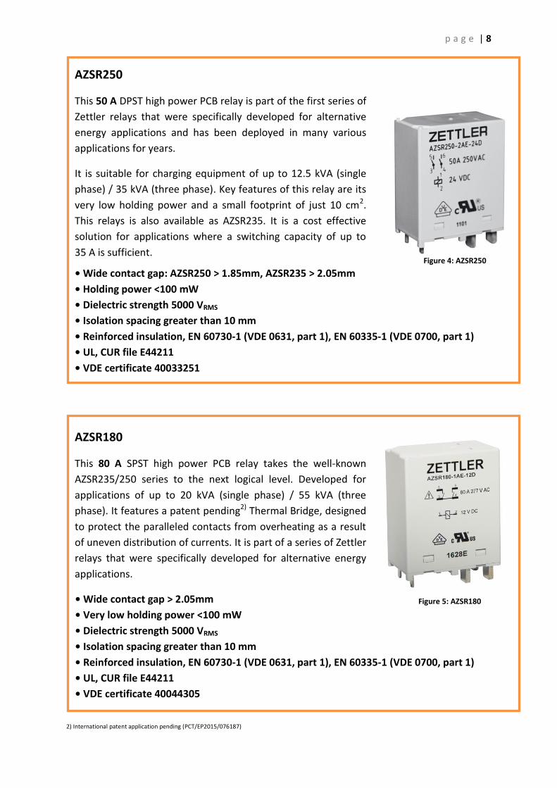
Figure 4: AZSR250
AZSR250
This 50 A DPST high power PCB relay is part of the first series of
Zettler relays that were specifically developed for alternative
energy applications and has been deployed in many various
applications for years.
It is suitable for charging equipment of up to 12.5 kVA (single
phase) / 35 kVA (three phase). Key features of this relay are its
very low holding power and a small footprint of just 10 cm2.
This relays is also available as AZSR235. It is a cost effective
solution for applications where a switching capacity of up to
35 A is sufficient.
• Wide contact gap: AZSR250 > 1.85mm, AZSR235 > 2.05mm
• Holding power <100 mW
• Dielectric strength 5000 VRMS
• Isolation spacing greater than 10 mm
• Reinforced insulation, EN 60730-1 (VDE 0631, part 1), EN 60335-1 (VDE 0700, part 1)
• UL, CUR file E44211
• VDE certificate 40033251
Figure 5: AZSR180
AZSR180
This 80 A SPST high power PCB relay takes the well-known
AZSR235/250 series to the next logical level. Developed for
applications of up to 20 kVA (single phase) / 55 kVA (three
phase). It features a patent pending2) Thermal Bridge, designed
to protect the paralleled contacts from overheating as a result
of uneven distribution of currents. It is part of a series of Zettler
relays that were specifically developed for alternative energy
applications.
• Wide contact gap > 2.05mm
• Very low holding power <100 mW
• Dielectric strength 5000 VRMS
• Isolation spacing greater than 10 mm
• Reinforced insulation, EN 60730-1 (VDE 0631, part 1), EN 60335-1 (VDE 0700, part 1)
• UL, CUR file E44211
• VDE certificate 40044305
p a g e | 9
Copyright ZETTLER Group 2016
3.3 ZETTLER AC circuit Relays for IEC mode 2 – Generation 2 charging
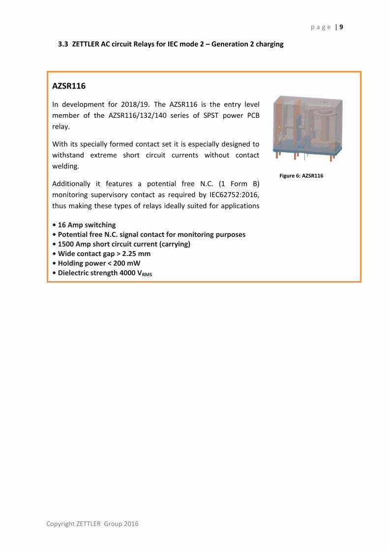
Figure 6: AZSR116
AZSR116
In development for 2018/19. The AZSR116 is the entry level
member of the AZSR116/132/140 series of SPST power PCB
relay.
With its specially formed contact set it is especially designed to
withstand extreme short circuit currents without contact
welding.
Additionally it features a potential free N.C. (1 Form B)
monitoring supervisory contact as required by IEC62752:2016,
thus making these types of relays ideally suited for applications
with high security demands. • 16 Amp switching • Potential free N.C. signal contact for monitoring purposes • 1500 Amp short circuit current (carrying) • Wide contact gap > 2.25 mm • Holding power < 200 mW • Dielectric strength 4000 VRMS

p a g e | 10
Figure 7: AZSR132
AZSR132
In development for 2018/19. The AZSR132 is the midrange
member of the AZSR116/132/140 series of SPST power PCB
relay.
With its unique contact set arrangement it is especially designed
to withstand extreme short circuit currents without contact
welding.
Additionally it features a potential free N.C. (1 Form B)
monitoring supervisory contact as required by IEC62752:2016,
thus making these types of relays ideally suited for applications
with high security demands. • 32 Amp switching • Potential free N.C. signal contact for monitoring purposes • 1500 Amp short circuit current (carrying) • Wide contact gap > 2.25 mm • Holding power < 200 mW • Dielectric strength 4000 VRMS
Figure 8: AZSR140
AZSR140
In development for 2018/19. The AZSR140 is the high current
version of the supervised AZSR116/132/140 series of SPST
power PCB relay.
Its contact set arrangement is especially designed to withstand
extreme short circuit currents without contact welding. In
addition its potential free N.C. (1 Form B) monitoring contact
makes this type the ideal choice for applications requiring with
high security and supervisory.
• 40 Amp switching • Potential free N.C. signal contact for monitoring purposes • 1500 Amp short circuit current (carrying) • Wide contact gap > 2.25 mm • Holding power < 200 mW • Dielectric strength 4000 VRMS

p a g e | 11
Copyright ZETTLER Group 2016
3.4 ZETTLER Contactors for SAE AC level 2 and IEC mode 3 charging
Figure 9: XMC0 Series Contactor
XMC0 Series
The XMC0 series of Definite Purpose Contactors are
electromechanical switching devices designed ideally for
stationary quick chargers.
With its high breaking capacity, this contactor is used for safety
cutoff of the charger circuit from the grid (power network) to
prevent abnormal currents
XMC0 contactors are built to the ARI 780/790 standard in our
ISO 9001 manufacturing facility for high performance and great
reliability. The XMC0 is available in various pole configurations
and load ratings up to 90 amps.
• A variety of termination options for specific application requirements • Universal mounting plate • Heavy-duty contacts ensure long electrical life • EE lamination (magnetic assembly) provides optimum performance while
reducing power consumption • Dust-free internal construction • UL, CUR file no. E222994
p a g e | 12
4 ZETTLER Magnetics – Current Sense Transformers
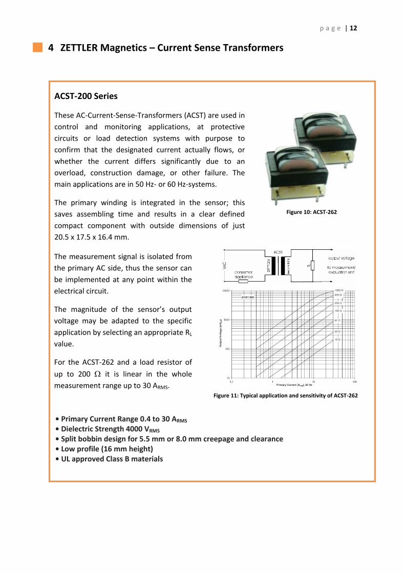
Figure 11: Typical application and sensitivity of ACST-262
ACST-200 Series
These AC-Current-Sense-Transformers (ACST) are used in
control and monitoring applications, at protective
circuits or load detection systems with purpose to
confirm that the designated current actually flows, or
whether the current differs significantly due to an
overload, construction damage, or other failure. The
main applications are in 50 Hz- or 60 Hz-systems.
The primary winding is integrated in the sensor; this
saves assembling time and results in a clear defined
compact component with outside dimensions of just
20.5 x 17.5 x 16.4 mm.
• Primary Current Range 0.4 to 30 ARMS • Dielectric Strength 4000 VRMS • Split bobbin design for 5.5 mm or 8.0 mm creepage and clearance • Low profile (16 mm height) • UL approved Class B materials
The measurement signal is isolated from
the primary AC side, thus the sensor can
be implemented at any point within the
electrical circuit.
The magnitude of the sensor’s output
voltage may be adapted to the specific
application by selecting an appropriate RL
value.
For the ACST-262 and a load resistor of
up to 200 it is linear in the whole
measurement range up to 30 ARMS.
Figure 10: ACST-262
p a g e | 13
Copyright ZETTLER Group 2016
5 AZ Displays – a member of the ZETTLER Group
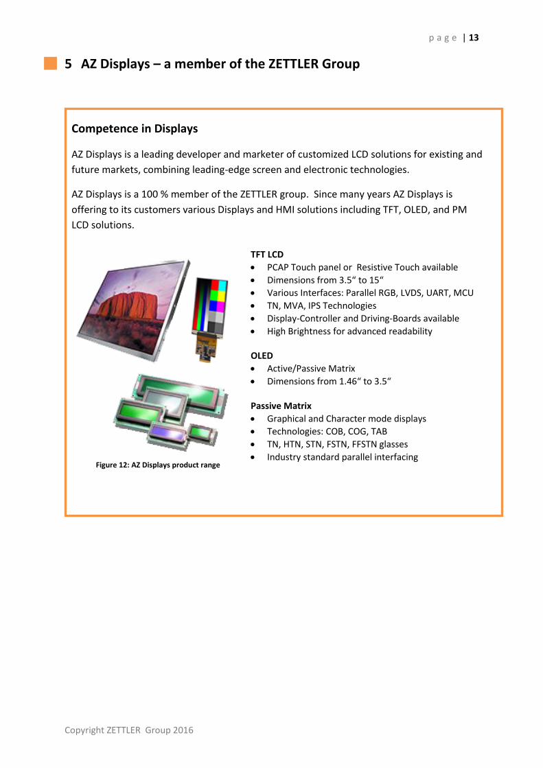
Figure 12: AZ Displays product range
Competence in Displays
AZ Displays is a leading developer and marketer of customized LCD solutions for existing and
future markets, combining leading-edge screen and electronic technologies.
AZ Displays is a 100 % member of the ZETTLER group. Since many years AZ Displays is
offering to its customers various Displays and HMI solutions including TFT, OLED, and PM
LCD solutions.
TFT LCD
PCAP Touch panel or Resistive Touch available
Dimensions from 3.5“ to 15“
Various Interfaces: Parallel RGB, LVDS, UART, MCU
TN, MVA, IPS Technologies
Display-Controller and Driving-Boards available
High Brightness for advanced readability OLED
Active/Passive Matrix
Dimensions from 1.46“ to 3.5“
Passive Matrix
Graphical and Character mode displays
Technologies: COB, COG, TAB
TN, HTN, STN, FSTN, FFSTN glasses
Industry standard parallel interfacing
p a g e | 14
6 ZETTLER Contacts
ZETTLER Group
www.zettler-group.com
North America
American Zettler Inc.
phone: +1 949-831-5000
www.azettler.com
Europe
ZETTLER electronics GmbH
phone: +49 89-800-97-0
www.zettlerelectronics.com
Asia
China Hong Kong
ZETTLER Relay (Xiamen) Co., Ltd. ZETTLER Electronics (HK) Ltd.
phone: +86 592-265-0988 X 975 phone: + 852 2375-1288
[email protected] [email protected]
www.zettlercn.com www.zettlerhk.com
|08.17v2


