44
Publicaon 5423-025-REV 1.1 Square Wave Electroporation System USER’S MANUAL

Publication 5423-025-REV 1.1
Square Wave Electroporation System
USER’S MANUAL

2 Publication 5423-025-REV 1.1 • www.btxonline.com
Research OnlyBTX
84 October Hill Rd Holliston, MA 01746, USA
Phone: 1-508-893-8999 Fax: 1-800-429-5732 Web: www.btxonline.com
WarrantyBTX warranties the ECM 830 Electroporation Systems for a period of two years from the date of purchase. At its option, BTX will repair or replace the unit if it is found to be defective as to workmanship or materials. This warranty does not extend to any instrumentation which has been (a) subjected to misuse, neglect, accident or abuse, (b) repaired or altered by anyone other than BTX without BTX express and prior approval, (c) used in violation of instructions furnished by BTX. This warranty extends only to the original customer purchaser. IN NO EVENT SHALL BTX BE LIABLE FOR INCIDENTAL OR CONSEQUENTIAL DAMAGES. Some states do not allow exclusion or limitation of incidental or consequential damages so the above limitation or exclusion may not apply to you. THERE ARE NO IMPLIED WARRANTIES OF MERCHANTABILITY, OR FITNESS FOR A PARTICULAR USE, OR OF ANY OTHER NATURE. Some states do not allow this limitation on an implied warranty, so the above limitation may not apply to you. Without limiting the generality of the foregoing, BTX shall not be liable for any claims of any kind whatsoever, as to the equipment delivered or for non-delivery of equipment, and whether or not based on negligence. Warranty is void if the ECM 830 instrument is changed in any way from its original factory design or if repairs are attempted without written authorization by BTX. Warranty is void if parts, connections or electrodes not manufactured by BTX are used with the ECM 830 instrument. If a defect arises within the warranty period, promptly contact BTX, 84 October Hill Road, Building 7, Holliston, Massachusetts, USA 01746-1388 using our toll free number 1-800-272-2775 (US Only) or 508-893-8999 (E-mail: [email protected]). Goods will not be accepted for return unless an RMA (Returned Materials Authorization) number has been issued by our customer service department. The customer is responsible for shipping charges. Please allow a reasonable period of time for completion of repairs, replacement and return. If the unit is replaced, the replacement unit is covered only for the remainder of the original warranty period dating from the purchase of the original device. This warranty gives you specific rights, and you may also have other rights, which vary from state to state.
Out of Warranty ServiceProceed exactly as for Warranty Service above. If our service department can assist you by phone or other correspondence, we will be glad to help at no charge.
Repair service will be billed on the basis of labor and materials. A complete statement of time spent and materials used will be supplied. Shipment to BTX should be prepaid. Your bill will include return shipment freight charges.
Disassembly by the user is prohibited. Service should only be carried out by experienced BTX technicians.
Repair Facilities and PartsBTX stocks replacement and repair parts. When ordering, please describe parts as completely as possible, preferably using our part numbers. If practical, enclose a sample photo or drawing.
Caution NoticeThe ECM 830 system is intended for laboratory use only and can be used in research and development applications. These systems have been designed to meet the standards for electromagnetic compatibility (EMC) and safety intended for laboratory equipment applications.
This product should not be used in the presence of a flammable atmosphere such as an anesthetic mixture with air, oxygen, or nitrous oxide.
Warranty Information

3 Publication 5423-025-REV 1.1 • www.btxonline.com
Please read the following safety precautions to ensure proper use of your generator. If the equipment is used in a manner not specified, the protection provided by the equipment may be impaired.
To Prevent Hazard or InjuryUse Proper Line Cord Use only the specified line cord for this product and make sure line cord is certified for country of use. The operating voltage range for the ECM 830 system is 100 – 240 vac, 50/60 Hz.
Ground the Product This product is grounded through the grounding conductor of the power cord. To avoid electric shock, the grounding conductor must be connected to earth ground. Before making any connections to the input or output terminals of the product, ensure that the product is properly grounded.
Make Proper Connections Make sure all connections are made properly and securely. Any signal wire connections to the unit must be no longer than three meters.
Observe All Terminal Ratings Review the operating manual to learn the ratings on all connections.
Use Proper Fuse Use only specified fuses with product.
Avoid Exposed Circuitry Do not touch any electronic circuitry inside of the product.
Do Not Operate with Suspected Failures If damage is suspected on or to the product do not operate the product. Contact qualified service personnel to perform inspection.
Orient the Equipment Properly Do not orient the equipment so that it is difficult to operate the disconnection device.
Place Product in Proper Environment Review the operating manual for guidelines for proper operating environments.
Observe All Warning Labels on Product Read all labels on product to ensure proper usage.
Caution Risk of Electric Shock
Caution Protective Ground Terminal
High Voltage RiskThese instruments contain a high voltage power supply adjustable to 3,000 V. High voltage power supplies present a serious risk of personal injury if not used in accordance with design and/or use specifications, if used in applications on products for which they are not intended or designed, or if they are used by untrained or unqualified personnel.
• The user must read this manual carefully before the instruments are placed into operation.
• Removing the cover will void the warranty.
• Do not connect or disconnect the high voltage cable with the high voltage enabled.
• To connect or disconnect the cable, turn line power off and unplug line (mains) cord.
• Do not touch the electrode tip while the waveforms are being applied.
If there are any questions about the operation of this instrument, call BTX Customer service at 1-800-272-2775, or 1-508-893-8999.
Caution NoticeThe ECM 830 Square Wave Electroporation System is intended for laboratory use only and can be used in research and development applications. These systems have been designed to meet the standards for electromagnetic compatibility (EMC) intended for laboratory equipment applications as well as the applicable safety requirements for electrical equipment for measurement, control, and laboratory use. The unit itself does not generate waste, but may be used to treat samples that are hazardous. Please use appropriate PPE and ensure disposal in accordance with local regulations and practices.
This product should not be used in the presence of a flammable atmosphere such as an anesthetic mixture with air, oxygen, or nitrous oxide.
Safety Information

4 Publication 5423-025-REV 1.1 • www.btxonline.com
A Message from BTX
Thank you for investing in a ECM 830 System.
Since its founding in 1983, the main focus of BTX has been in the area of applying controlled electric fields for genetic engineering applications. Because of this, we quickly established a reputation as the technological leader in the fields of electroporation and electrofusion. Our systems have been installed in many prestigious institutes around the globe where they are used successfully for high efficiency transfection, transformation and cell fusion applications. We offer a variety of waveforms, electrodes and chamber options to provide you with the best tools to achieve your goals.
We are vested in your success. To that end, the BTX technical support team constantly tracks published literature for any reference to electroporation and electrofusion. We extract the pertinent experimental conditions and yields from these papers to help us in our efforts to help you. In addition to tracking publications, we are available to you for support at any time for advice in experimental design, product recommendations, troubleshooting, and any other relevant technical advice.
We thank you again for your investment and we look forward to assisting you in any way we can.
Finally, please read this manual carefully before attempting to operate the electroporation system. If you have any questions about the unit or about particular applications, please contact us:
BTX 84 October Hill Road Holliston, MA 01746 USA
Toll Free: 1-800-272-2775 International Callers: 508-893-8999 Fax: 508-429-5732 Web: www.btxonline.com Email: [email protected]
For any customers outside the US or Canada, please call your local BTX dealer or call us directly.

5 Publication 5423-025-REV 1.1 • www.btxonline.com
SUBJECT PAGE #Warranty Information 2Safety Information 3Introduction 4Table of Contents 5 – 6Product Overview 7Unpacking the System 8Touchscreen Button Reference 9Software Setup 10 – 12 Setting Time/Date 10 Setting Audible Alarm Preferences 10 Setting Backlight Preferences 11 Displaying Device Information 11 Toggling Auto-PrePulse 12Preset Protocols 13 – 15 Using Preset Protocols 13 Customizing a Preset Protocol 14 – 15Performing Experiments 16 – 18 Creating New Protocols 16 – 18Using Specialty Protocols 19 – 21 Using an HT Plate Handler 19 – 20 Using Specialty Electrodes 21Managing Protocols 22 – 24 Saving a Copy of a Protocol 22 Renaming a Protocol 22 Deleting a Protocol 23 Password Protecting a Protocol 24Protocol Manager Software 25 – 27 Installation 25 Overview 25 Upload from Generator to PC 25 Download from PC to Generator 26 Upload Log Files 27Remote Control Software 28Generator Specifications 29Maintenance 30Upgrading ECM 830 Series Software 31 – 33 USB Virtual CommPort Driver Installation 31 – 32 Firmware Updater Program 33Error Messages & Troubleshooting 34 – 36
Table of Contents

6 Publication 5423-025-REV 1.1 • www.btxonline.com
Table of Contents
SUBJECT PAGE #General Optimization Guide for Electroporation 37 – 39 DNA Delivery into Cells Using Electroporation 37 Waveforms 38 Field Strength 38 Pulse Length 39 Number of Pulses 39 Electroporation Buffer 39 DNA/RNA Concentrations 39Applications 40 Mammalian Cell Transfection 40 In Vivo, In Utero, In Ovo 40Electroporation Buffers 41Ordering Information 42 – 44
7 Publication 5423-025-REV 1.1 • www.btxonline.com
Product Overview
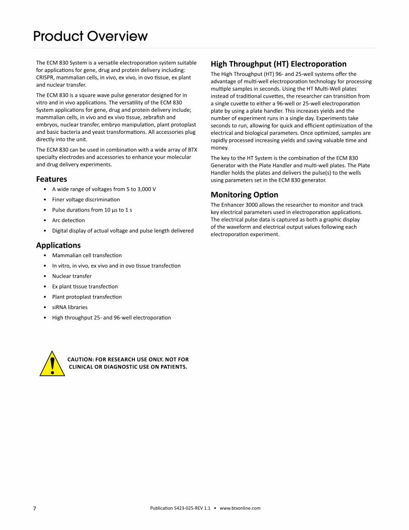
High Throughput (HT) Electroporation The High Throughput (HT) 96- and 25-well systems offer the advantage of multi-well electroporation technology for processing multiple samples in seconds. Using the HT Multi-Well plates instead of traditional cuvettes, the researcher can transition from a single cuvette to either a 96-well or 25-well electroporation plate by using a plate handler. This increases yields and the number of experiment runs in a single day. Experiments take seconds to run, allowing for quick and efficient optimization of the electrical and biological parameters. Once optimized, samples are rapidly processed increasing yields and saving valuable time and money.
The key to the HT System is the combination of the ECM 830 Generator with the Plate Handler and multi-well plates. The Plate Handler holds the plates and delivers the pulse(s) to the wells using parameters set in the ECM 830 generator.
Monitoring OptionThe Enhancer 3000 allows the researcher to monitor and track key electrical parameters used in electroporation applications. The electrical pulse data is captured as both a graphic display of the waveform and electrical output values following each electroporation experiment.
The ECM 830 System is a versatile electroporation system suitable for applications for gene, drug and protein delivery including: CRISPR, mammalian cells, in vivo, ex vivo, in ovo tissue, ex plant and nuclear transfer.
The ECM 830 is a square wave pulse generator designed for in vitro and in vivo applications. The versatility of the ECM 830 System applications for gene, drug and protein delivery include; mammalian cells, in vivo and ex vivo tissue, zebrafish and embryos, nuclear transfer, embryo manipulation, plant protoplast and basic bacteria and yeast transformations. All accessories plug directly into the unit.
The ECM 830 can be used in combination with a wide array of BTX specialty electrodes and accessories to enhance your molecular and drug delivery experiments.
Features• A wide range of voltages from 5 to 3,000 V
• Finer voltage discrimination
• Pulse durations from 10 μs to 1 s
• Arc detection
• Digital display of actual voltage and pulse length delivered
Applications • Mammalian cell transfection
• In vitro, in vivo, ex vivo and in ovo tissue transfection
• Nuclear transfer
• Ex plant tissue transfection
• Plant protoplast transfection
• siRNA libraries
• High throughput 25- and 96-well electroporation
CAUTION: FOR RESEARCH USE ONLY. NOT FOR CLINICAL OR DIAGNOSTIC USE ON PATIENTS.

8 Publication 5423-025-REV 1.1 • www.btxonline.com
The shipping carton in which your ECM 830 Electroporation System is packed has been specifically designed to provide maximum protection to the instrument during transportation and normal handling conditions. Upon receipt, the carton should be examined for any external damage resulting from shipment.
Open the carton and carefully remove the ECM 830 system and inspect the unit for any apparent damage. Save the carton and packing materials for future transportation and shipping requirements.
Packing DataCheck the packing slip to ensure that all items ordered and listed are included in the shipment. Inform BTX immediately if any parts are missing or damaged.
Power SourceAs received, the instrument is ready for use with either 100–240 V AC, 50/60 HZ.
The power requirements are 350 watts. In the USA, the power cord has a standard three prong plug.
InstallationOnce you have determined that the components of the system have not sustained any obvious damage in shipment, proceed with the installation.
Remove the insulating tab from the battery at the base of the unit.
Place the generator in a location that is a dry, level, sturdy surface free from extremes in ambient temperature, dust or chemical exposures. Allow the device to equilibrate to room temperature.
Unpack the safety dome, cuvette rack and disposable cuvette chambers. Connect the safety dome, specialty electrode, or the HT plate handler into the connectors at the bottom right-hand side of the front panel.
Connect the mains/power cord to into the back panel at the bottom left.
Power up the system by pushing the rocker switch located on the back panel at the bottom left. The display will flash the BTX logo. Once the software initializes, the Main Menu screen will appear.
You are now ready to begin your work.Main Power Switch
Fuse Holder
Universal Power Input
USB Serial Input Footswitch Input(switch sold separately)
High Voltage Output
Touchscreen Display
Unpacking the System
Remove Battery Insulating Tab.

9 Publication 5423-025-REV 1.1 • www.btxonline.com
Touchscreen Icons Reference
AcceptUsed to accept the parameters/settings on a screen and advance to the next screen in the menu, also used in place of a double tap on various icons.
BackUsed to go back one screen.
CancelUsed to cancel any changes/entries on a screen and return to the previous screen in the menu.
File OptionsAccess the File Option menu that is used to save, rename and delete protocols.
Home/Main MenuAccess Preset Protocols, User Protocols and Settings.
Page DownUsed to page down in a display list.
Page UpUsed to page up in a display list.
Scroll DownUsed to scroll down in a display list.
Scroll UpUsed to scroll up in a display list.
Pre-Pulse Resistance MeasurementAlso referred to as Omega Icon. Used to measure the resistance of the sample prior to delivering the DC pulse.
Run ProtocolUsed to deliver the pulse protocol to the sample.
SettingsAlso referred to as Gear icon. Access the settings menu used to adjust the following parameters: Date and Time, Audible Alarms, Backlighting, and software updates. Displays device information.
Stop ProtocolUsed during the pulse delivery sequence to stop the progress of the protocol.
Square Wave IndicatorUsed to indicate when a protocol utilizes square wave pulses.
Protocol LockedIndicates that changes to the protocol are currently locked. Press the icon and enter password to unlock the protocol.
Protocol UnlockedIndicates that changes to the protocol are currently unlocked. Pressing the icon twice will allow the user to password protect the protocol.
Notification Box Quick ReferenceInformation / Status MessageProvides information or guidance for next steps, including acceptable ranges for protocol programming.
Warning MessageRequires Notification Box tap for acknowledgement of information, but does not prevent operation of the system.
Failure MessageCaused by user input error, failure of a protocol, or a system error. Requires user to correct this issue in order to complete the operation.

10 Publication 5423-025-REV 1.1 • www.btxonline.com
Setting Time/DateAfter initializing, the home screen will appear.
Tap the Gear icon.
1
1
5
3
Tap Time/Date icon.
Tap Date icon and use the keypad to type the date.
Tap Time icon and use the keypad to type the time.
Tap the Green Check icon to save and return to the settings screen.
Setting Audible Alarm PreferencesOn the home screen, tap the Gear icon.
Tap Audible Alarms icon.
Select preferred audible alarms by tapping the icons to activate or deactivate.
Tap the Green Check icon to save and return to the settings screen.
Software Setup
NOTE: You may change the date and time format by tapping icons to the right of the given values.

11 Publication 5423-025-REV 1.1 • www.btxonline.com
Setting Backlight PreferencesOn the home screen, tap the Gear icon.
Tap Backlight icon. Tap Device Information icon.
Select preferred brightness by tapping the icon indicating % brightness.
Tap the Green Check icon to save and return to the settings screen.
View device information.
Tap the Green Check icon to return to the settings screen.
1 1
7
Displaying Device InformationOn the home screen, tap the Gear icon.
Software Setup

12 Publication 5423-025-REV 1.1 • www.btxonline.com12
1
Software Setup
Toggling Auto-PrePulse Off/On
NOTE: Default instrument settings include an automatic square wave PrePulse of approximately 17 volts, 30 ms duration executed prior to protocol programmed pulse(s) to measure sample resistance and configure the equipment prior to running. When a PrePulse runs, a PrePulse instrument log is recorded which includes Date, Time, Model, Mode, Protocol Name, and Sample Resistance (“Load,” in Ohms). The PrePulse log file name is the same as an experimental pulse log file name, except with a PP appended to the end, for example “222412PP.txt.”
NOTE: When Auto-PrePulse is disabled, sample resistance is no longer recorded in the experimental log. In both situations whether Auto-Prepulse is enabled or disabled, the user has the option to manually run a Pre-Pulse sample resistance check and log PrePulse data. To run a manual PrePulse, tap the Ohm icon on the protocol run screen. This allows the user the ability to perform a manual sample resistance PrePulse check and log Prepulse data on a duplicate sample separate from an experimental sample protocol run with the Auto-PrePulse feature disabled.
From the main menu or the protocol run screen, tap the Gear icon to go to Settings.
Auto-PrePulse default setting is On.
Auto-PrePulse may be deactivated by tapping Off icon or activated by tapping On icon. Selected Auto-PrePulse settings are maintained if instrument is power cycled.

13 Publication 5423-025-REV 1.1 • www.btxonline.com
10
11
12
Using Preset ProtocolsOn the home screen, tap the Preset Protocols icon.
Double tap desired cell type.
Scroll through available cells.
Tap desired cells.
13
74
73
Using Preset Protocols (continued)Review parameters.
Tap Omega icon to measure pre-pulse load resistance.
With load measurement OK, press the Green ‘Go’ icon to run protocol.
Once protocol is complete, data regarding your pulse is displayed and stored in the systems logs for future use.
You may continue pulsing, go back to the protocol select screen, or to the home screen.
Preset Protocols

14 Publication 5423-025-REV 1.1 • www.btxonline.com
10
11
14
Customizing a Preset ProtocolOn the home screen, tap the Preset Protocols icon.
Double tap desired cell type.
Scroll through available cells.
Tap desired cells.
Tap Folder icon.
Customizing a Preset Protocol (continued)Use keyboard to name copy of protocol.
Tap the Green Check icon to save.
Tap the Home icon.
On the home screen, tap User Protocols icon.16
17
Preset Protocols
15 Publication 5423-025-REV 1.1 • www.btxonline.com
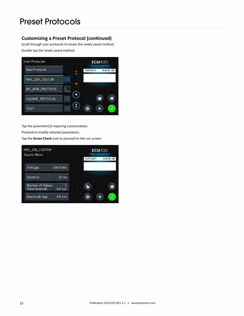
Customizing a Preset Protocol (continued)Scroll through user protocols to locate the newly saved method.
Double tap the newly saved method.
Tap the parameter(s) requiring customization.
Proceed to modify selected parameters.
Tap the Green Check icon to proceed to the run screen.
Preset Protocols

16 Publication 5423-025-REV 1.1 • www.btxonline.com
Double tap New Protocol.
Use keyboard to name protocol.
Tap the Green Check icon to save.
Creating New ProtocolsOn the home screen, tap User Protocols icon.
17
17
24
Creating New Protocols On the home screen, tap User Protocols icon.
Tap your newly saved protocol.
Tap the Voltage icon.
Use the numeric keypad to set voltage.
Tap the Green Check icon to save.
Performing Experiments

17 Publication 5423-025-REV 1.1 • www.btxonline.com
Use the numeric keypad to set duration of pulse.
Tap Number of Pulses / Pulse Interval icon.
Tap the Number of Pulses.
Use the numeric keypad to set the # of pulses.
Creating New Protocols (continued)Tap the Duration icon.
26
30
Tap the Pulse Interval (sec) icon.
Use the numeric keypad to set the interval between pulses.
Tap the Green Check icon to save.
Performing Experiments
NOTE: Intervals must only be set when performing multiple pulsing.

18 Publication 5423-025-REV 1.1 • www.btxonline.com
Use the numeric keypad to set the gap between electrodes.
Tap the Green Check icon to save.
Creating New Protocols (continued)Tap the Electrode Gap icon.
View your protocol.
To run, tap the Omega icon.
32 Tap the Green Check icon to proceed to the run screen.
With load measurement OK, press the Green ‘Go’ icon to run protocol.
Once protocol is complete, data regarding your pulse is displayed and stored in the systems logs for future use.
You may continue pulsing, go back to set-up screen, or to the home screen.
Performing Experiments
NOTE: See the Protocol Manager Software section for instructions on viewing and downloading log data.

19 Publication 5423-025-REV 1.1 • www.btxonline.com
Review parameters.
Tap Plate Handler icon.
50
52
53
54 51
Using the numeric keypad icon, type the number of columns being pulsed.
Tap the Green Check icon to save.
Review parameters.
Set the HT plate handler with the correct number of pre-pulse resistance measurement and DC pulses.
Tap green Information Screen to clear message.
Tap the Green ‘Go’ icon to run protocol.
The Red ‘x’ icon can be used to stop the protocol at any time.
Using an HT Plate HandlerPlug the HT Plate Handler into the front ports of the ECM 830 unit.
Select desired protocol (preset protocol or user protocol).
Double tap desired cells.
49
Using Specialty Protocols
NOTE: Generator will display readings of the 1st and last pulse of each column.
NOTE: Note the message box. It will indicate how many pulses should be set on the HT plate handler. This number will be a combination of both pre-pulse resistance measurements and DC pulses.

20 Publication 5423-025-REV 1.1 • www.btxonline.com
Using Specialty ElectrodesPlug the specialty electrodes into the front ports of the BTX ECM 830.
Scroll through available protocols.
Double tap desired selection.
Scroll through available tissue/cell types.
Double tap desired tissue/cell.
Review parameters.
Position electrodes on area being electroporated.
To run tap the Omega icon.
57
80
81
55
56
With load measurement OK, press the Green ‘Go’ icon to run protocol.
While the pulse is being delivered, the Red ‘x’ icon can be used to stop the protocol at any time.
79
Using an HT Plate Handler (continued)Once protocol is complete, data regarding your pulse is displayed and stored in the systems logs for future use.
You may continue pulsing, go back to the settings screen or protocol select screen, or to the home screen.
Using Specialty Protocols
NOTE: Generator will display readings after first and last pulse.

21 Publication 5423-025-REV 1.1 • www.btxonline.com
82
Using Specialty ElectrodesOnce protocol is complete, data regarding your pulse is displayed and stored in the systems logs for future use.
You may continue pulsing, go back to the settings screen or the protocol select screen, or to the home screen.
Using Specialty Protocols

22 Publication 5423-025-REV 1.1 • www.btxonline.com
All preset and user protocols are stored in the protocol list for ongoing use. Over time, you may want to manage previously created protocols to keep your protocol list easy to navigate. In addition, the ecm 830 allows you to export protocol information to an externally connected generator or to a computer that will be used to control operation. This section describes the file management facilities available on the ECM 830.
Preset protocols cannot be edited or deleted but may be saved as a new user protocol where they can be edited, deleted or renamed.
Saving a Copy of a Protocol Follow these instructions to save a copy of a protocol under a new name:
1. From the list of available Protocols, select (press once) the Protocol you want to save a copy of, then choose the File Options icon to enter the File Options screen.
2. Choose Save As/Copy to access the Protocol Name Entry screen. The current protocol name will be displayed in the text entry box.
3. On the Protocol Name screen, type the new name for your protocol using the onscreen keyboard. Choose the Symbols / Numbers icon (.@123) to display the list of available numbers and symbols that can be included in the Protocol Name. To switch the keyboard back to letters mode, choose the Letters icon (ABC). [15 characters maximum]
4. When finished entering the new Protocol Name, choose the Green Check icon to save your changes.
58
Renaming a Protocol Follow these instructions to rename a previously saved user protocol:
1. From the list of available Protocols, select (press once) the Protocol you want to rename, then choose the File Options icon to enter the File Options screen.
2. Choose Rename Protocol to access the Protocol Name Entry screen.
3. On the Protocol Name screen, type the new name for your protocol using the onscreen keyboard. Choose the Symbols / Numbers button (.@123) to display the list of available numbers and symbols that can be included in the protocol name. To switch the keyboard back to letters mode, choose the Letters icon (ABC). [15 characters maximum]
4. When finished entering the new protocol name, choose the Green Check icon to save your changes.
60
Managing Protocols
NOTE: If saving a Preset Protocol as a new User Protocol, the File Options icon will directly open up to the Protocol Name screen.
23 Publication 5423-025-REV 1.1 • www.btxonline.com
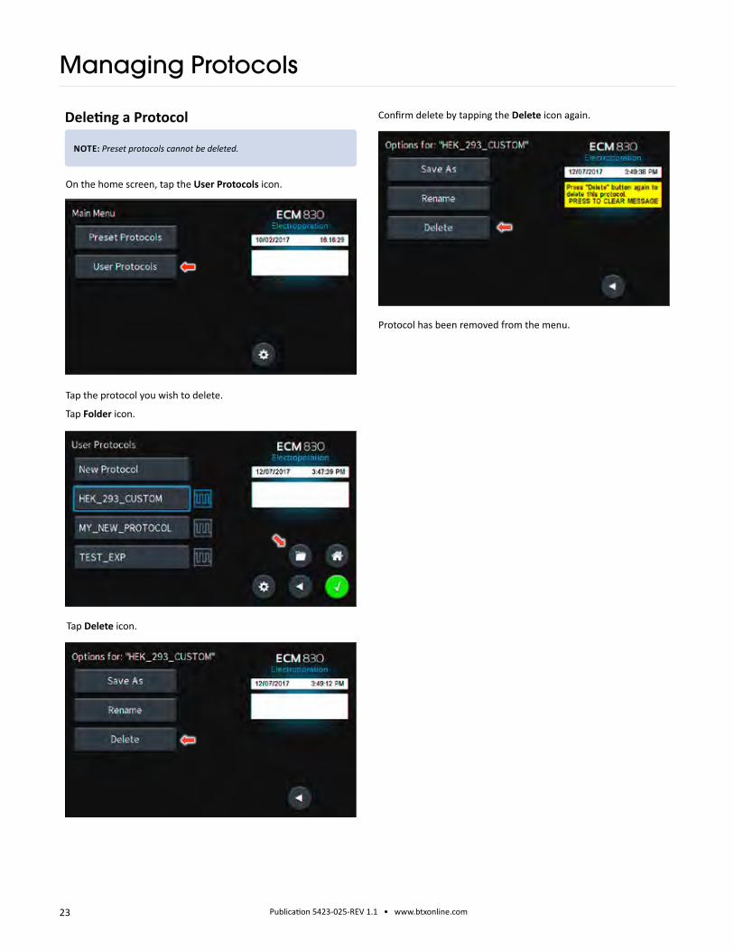
On the home screen, tap the User Protocols icon.
Tap the protocol you wish to delete.
Tap Folder icon.
Tap Delete icon.
Confirm delete by tapping the Delete icon again.Deleting a Protocol
17
Protocol has been removed from the menu.
Managing Protocols
NOTE: Preset protocols cannot be deleted.

24 Publication 5423-025-REV 1.1 • www.btxonline.com
Password Protecting a User ProtocolOn the home screen, tap the User Protocols icon.
Double tap protocol you wish to password protect.
View the protocol.
Tap the Open Lock icon.
17
Confirm password protection by tapping the Open Lock icon again.
Use the numeric keypad to set the password.
Tap the Green Check icon to save.
The protocol is now locked against modifications.
To unlock press the Lock icon. Type in the password then tap the Green Check icon.
Managing Protocols

25 Publication 5423-025-REV 1.1 • www.btxonline.com
InstallationDownload the software from BTX website www.btxonline.com. Click on Technical Resources drop-down menu and select Downloads. Download and install file named Protocol Manager.
1. Connect the generator to the PC using a USB cable.
2. Turn the generator on.
3. Start Protocol Manager.
4. Select the proper COM port.
OverviewProtocol Manager allows the user to:
• Upload protocols from the ECM 830 generator to a PC.
• Download protocols from a PC to the ECM 830 generator.
• Upload log files from the ECM 830 generator to a PC.
Log FileControl
PC to GeneratorProtocol Control
Generator to PCProtocol Control
Upload from Generator to PC1. Select Protocol(s).
2. Click ‘Save Protocol’.
3. Select the drive and folder location.
4. Click ‘Save’.
Protocol Manager Software
NOTE: Compatible with Windows® XP or later.
NOTE: Hit ‘Refresh’ to update the list after creating or editing protocols on the ECM 830 generator.

26 Publication 5423-025-REV 1.1 • www.btxonline.com
Download from PC to Generator1. Click ‘Choose Protocol’.
2. Select protocol(s) to download.
3. Click ‘Open’.
4. Protocol name being downloaded is shown.
Protocol Manager Software
NOTE: If a protocol already exists on the ECM 830 generator, Protocol Manager will not overwrite the file if you attempt to re-download it.

27 Publication 5423-025-REV 1.1 • www.btxonline.com
Upload Log Files1. On the main screen, click ‘Pulse Data’.
2. Select your desired files or folders and then click ‘Transfer’.
3. Select the drive or folder location.
Troubleshooting Protocol Manager1. Do not upload/download protocols while generator is
running. Program works best while generator is idle on protocol setup screen.
2. Order of Operations:
A. Connect USB.
B. Turn generator on.
C. Start Protocol Manager program.
Protocol Manager Software
NOTE: Log Files are saved as a tab delimited text file. They can be opened with any common text editor like Notepad or by using spreadsheet software such as Excel.
NOTE: Files should be backed up periodically. The generator’s SD card can store up to approximately 100,000 files.

28 Publication 5423-025-REV 1.1 • www.btxonline.com
InstallationDownload the software from the BTX website www.btxonline.com. Click on Technical Resources drop-down menu and select Downloads. Download and install file named Remote Screen Interface.
OverviewRemote Screen Interface allows you to control the ECM 830 remotely. When you click on the computer screen, you control the generator.
While the ECM 830 generator is connected to the computer via USB, open the Control Panel and select System and Security, and then System. Click Device Manager on the left hand menu. Under Ports, search for the ‘USB serial port for ECM 830.’ This will show the COM Port to which the generator is connected, as shown below.
Once the COM port is known, open the Remote Screen Interface application. Choose the correct COM port and click ‘Connect’.
You should now be able to control your ECM 830 generator remotely.
Remote Control Software
NOTE: During the installation, it will ask you to provide a location to install your application files. There is a known issue with this installer where it will not actually create this directory.

29 Publication 5423-025-REV 1.1 • www.btxonline.com
Generator Specifications
ECM 830Square Wave Pulse RangesVoltage Range LV Mode 5 to 500 in 1 V steps HV Mode 505 to 3000 in 5 V stepsVoltage Accuracy LV Mode 5% HV Mode 5%Pulse Length Range
LV Mode 10 to 999 µs in 1 µs step 1 to 999 ms in 1 ms step
HV Mode 10 to 600 µs in 1 µs stepMultiple Pulsing LV Mode 1 to 99 pulses per sample HV Mode 1 to 99 pulses per samplePulse Interval 0.1 s to 10 s
Capacitance in µF
LV Mode 3775 µF HV Mode 85 µFVoltage Droop 20% Load <1 K Ω, 10% Load >1 K Ω
Sample Resistance (Load)
LV Mode PL ≤100 ms, load ≥8 to 9 Ω PL >100 ms, load ≥100 Ω
HV Mode Load ≥40 Ω
Other SpecificationsCharging Time LV <7 s, HV <4 s
Monitoring Pulse Voltage, Width, Droop % and Sample Resistance
Display 7.0-in color displayControls Touch ScreenProgrammability Storage over 1000 ProtocolsArc Control Yes
Other SpecificationsInterlock Switches YesPre-Pulse Sample resistance check Yes
Pulse Over Current Protection
Yes
PC control YesPC communications YesLog Report YesRemote Operation YesFoot Switch Control YesPower Ratings 35 W idle and 350 W pulsingInput Voltage ratings 100 to 240 VACDimensions (H x W x D) inches
12.75 x 11.25 x 8.5
Weight ~16 lbWarranty 2 yearsOperating Temperature 4°C to 40°C (40°F to 104°F)Storage Temperature -10°C to 70°C (14°F to 158°F)Operating Humidity 20% to 80% RH, non-condensingStorage Humidity 20% to 80% RH, non-condensingMode of Operation ContinuousClassification Class IPollution IP2XInstallation Category IISupplier Name BTX
Supplier Address 84 October Hill Rd. Holliston, MA 01746
Supplier Phone Number 508-893-8999
Regulatory Certifications CE, ETL (UL, CSA), FCC, WEEE, EU RoHS & CB Scheme

30 Publication 5423-025-REV 1.1 • www.btxonline.com
The ECM 830 generator requires no special maintenance other than keeping it clean.
To clean the exterior surfaces, use a lint-free cloth to remove loose dust. Use care to avoid scratching the clear display window. For more efficient cleaning, use a soft cloth dampened (not soaked) with an aqueous solution of 75% isopropyl alcohol, or a mild detergent.
Fuse ReplacementKey Information
1. Make sure the power cord is disconnected from the main supply before servicing the fuse.
2. Use only Type 3AG, 1/4 x 11/4 in, 5 amp, 250 volt; Type T (time delay) fuses.
Turn off power and remove power cord from power module. Use a straight blade screwdriver to pry open the access door. Remove the fuse holder and then remove the fuses from this holder as shown in figure below. Replace fuses, and then replace the fuse holder.
Battery Replacement (Underside of Instrument)
1. Disconnect from mains power supply.
2. Remove screw and swing cover to the side.
3. Slide battery out from under clip.
4. Install Lithium Coin Battery: 3V, 16mm CR1620 by sliding under clip with positive side facing out.
Maintenance
CAUTION: Use only same type and rated battery. Observe polarity when installing.
31 Publication 5423-025-REV 1.1 • www.btxonline.com
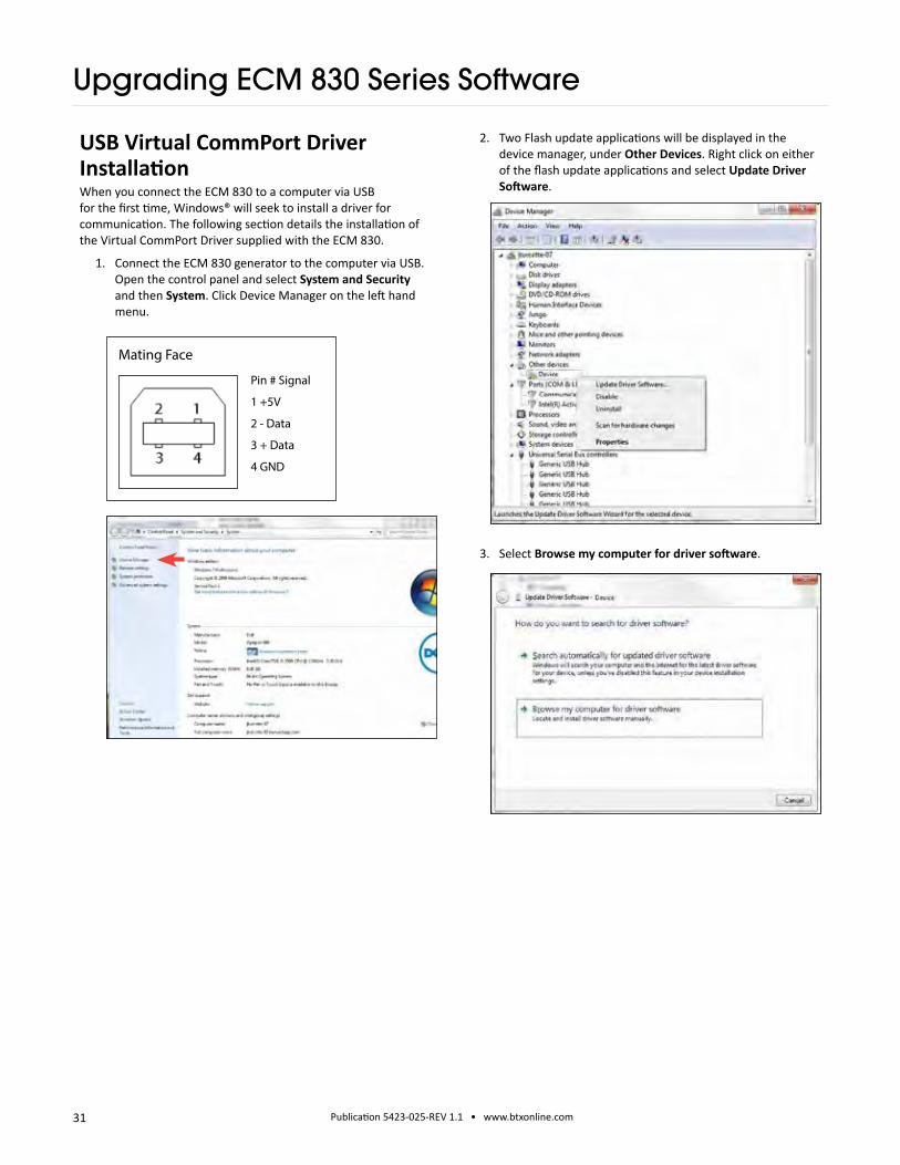
USB Virtual CommPort Driver Installation When you connect the ECM 830 to a computer via USB for the first time, Windows® will seek to install a driver for communication. The following section details the installation of the Virtual CommPort Driver supplied with the ECM 830.
1. Connect the ECM 830 generator to the computer via USB. Open the control panel and select System and Security and then System. Click Device Manager on the left hand menu.
Pin # Signal
1 +5V
2 - Data
3 + Data
4 GND
Mating Face
2. Two Flash update applications will be displayed in the device manager, under Other Devices. Right click on either of the flash update applications and select Update Driver Software.
3. Select Browse my computer for driver software.
Upgrading ECM 830 Series Software

32 Publication 5423-025-REV 1.1 • www.btxonline.com
6. Click Close after the software has been successfully installed.
5. If a warning message regarding the driver publisher is displayed, choose Install this driver software anyway.
USB Virtual CommPort Driver Installation (continued)
4. Download the software from BTX website www.btxonline.com. Click on the Technical Resources drop-down menu and select Downloads. Download and install file named Firmware Updater.
Upgrading ECM 830 Series Software

33 Publication 5423-025-REV 1.1 • www.btxonline.com
1. Upload the latest software versions to your desktop (format is filename.srec). There is one .srec file that needs to be updated: ‘APP BTX_Gemini_upgrade x.x.x’.
2. Disconnect all I/O devices and then connect the ECM 830 generator to the PC using a USB cable.
3. On the setup screen of the ECM 830 generator, press the Upgrade Software icon twice to enter Boot Loader Mode.
4. Download the software from the BTX website www.btxonline.com. Click on the Technical Resources drop-down menu and select Downloads. Download and install file named Firmware Updater.
5. Click Open Update File and browse to the BTX Gemini 7 vx.x.x.srec’. file that was previously saved to the desktop.
6. Click Start Update.
7. After the update is complete, press Reboot and then power cycle the ECM 830 generator from the power switch in the
back of the unit.
Firmware Updater Program
Upgrading ECM 830 Series Software
NOTE: Prior to upgrading, users will need to install USB drivers as well as the bootloader driver file. Reference ‘Virtual Comport Driver Installation’.
NOTE: To exit boot loader mode without upgrading the software, power cycle the generator.

34 Publication 5423-025-REV 1.1 • www.btxonline.com
Display Error Message Error Description User TroubleshootingPower Loss Error Power loss during pulsing. Power lost while protocol was running.PFC Over Temp PFC module over temperature. Hardware error. Please contact the manufacturer.Interlock Open Electrode interlock open. Connect electrode connectors to the front of the generator and make
sure the cuvette safety dome cover is closed.IGBT Switch Fault IGBT switches fault. Hardware error. Please contact the manufacturer.Charge Voltage Max Error Charging voltage above the expected voltage. Turn off the unit for a few minutes then turn back on. Rerun the protocol.
If the issue recurs, contact the manufacturer.Charge Current Max Error Charging current above the expected current. Turn off the unit for a few minutes then turn back on. Rerun the protocol.
If the issue recurs, contact the manufacturer.LV Cap Bank Max Low voltage capacitor bank voltage above expected value. Turn off the unit for a few minutes then turn back on. Rerun the protocol.
If the issue recurs, contact the manufacturer.LV Cap Bank Min Low voltage capacitor bank voltage below expected value. Turn off the unit for a few minutes then turn back on. Rerun the protocol.
If the issue recurs, contact the manufacturer.HV Cap Bank Max High voltage capacitor bank voltage above expected value. Turn off the unit for a few minutes then turn back on. Rerun the protocol.
If the issue recurs, contact the manufacturer.HV Cap Bank Min High voltage capacitor bank voltage below expected value. Turn off the unit for a few minutes then turn back on. Rerun the protocol.
If the issue recurs, contact the manufacturer.Charge Time Max Charging capacitor bank to selected voltage exceeded max time estimated. Turn off the unit for a few minutes then turn back on. Rerun the protocol.
If the issue recurs, contact the manufacturer.Pulse Droop Error Pulse voltage droop exceeded estimated droop. A) Increase the sample resistance. This can be achieved by:
1. Increasing the gap size. 2. Reducing the volume. 3. Using a less conductive buffer.B) Reduce the pulse duration.
Pulse Voltage Overshoot Pulse voltage monitor (p-vmon) pulse overshoot. Hardware error. Please contact the manufacturer. Pulse Voltage Mon too Low Pulse voltage monitor (p-vmon) below min voltage. Hardware error. Please contact the manufacturer. Pulse Voltage Mon too High Pulse voltage monitor (p-vmon) above max voltage. Hardware error. Please contact the manufacturer. Pulse Current Mon too Low Pulse current monitor (p-imon) below min current. Hardware error. Please contact the manufacturer. Pulse Current Mon too High Pulse current monitor (p-imon) above max current. Hardware error. Please contact the manufacturer. Arc_Detected Arc detected during pulsing. Arc could happen due to the one or more of the following conditions:
1. Sample resistance is very low for the voltage selected. 2. Gap size is too small for the voltage selected. 3. Pulse duration is too long.
No_HB_from_GUI Communication error. Hardware error. Please contact the manufacturer Sample Resistance Out Of Range
The measured sample load is out of range. Increase the sample resistance. This can be achieved by: 1. Increasing the gap size. 2. Reducing the volume. 3. Replacing the buffer with less conductive type of buffer.
Over Current Pulse Abort Pulse aborted due to pulse over current. The over current protection feature is added to prevent sample arcing. This could occur when the sample resistance changes during the pulse: 1. Sample resistance is very low for the voltage selected. 2. Gap size is too small for the voltage selected. 3. Pulse duration is too long.
Idle V I Max Voltage or current in idle state is higher than expected. Turn off the unit for a few minutes then turn back on. Rerun the protocol. If the issue recurs, contact the manufacturer.
Charge Cap Bank A Max Charge capacitor bank A voltage is above tolerance. Turn off the unit for a few minutes then turn back on. Rerun the protocol. If the issue recurs, contact the manufacturer.
Charge Cap Bank A Min Charge capacitor bank A voltage is below tolerance. Turn off the unit for a few minutes then turn back on. Rerun the protocol. If the issue recurs, contact the manufacturer.
Charge Cap Bank B Max Charge capacitor bank B voltage is above tolerance. Turn off the unit for a few minutes then turn back on. Rerun the protocol. If the issue recurs, contact the manufacturer.
Charge Cap Bank B Min Charge capacitor bank B voltage is below tolerance. Turn off the unit for a few minutes then turn back on. Rerun the protocol. If the issue recurs, contact the manufacturer.
Charge Cap Bank C Max Charge capacitor bank C voltage is above tolerance. Turn off the unit for a few minutes then turn back on. Rerun the protocol. If the issue recurs, contact the manufacturer.
Charge Cap Bank C Min Charge capacitor bank C voltage is below tolerance. Turn off the unit for a few minutes then turn back on. Rerun the protocol. If the issue recurs, contact the manufacturer.
Dump Time Max The capacitor bank did not fully discharge in the estimated time. Turn off the unit for a few minutes then turn back on. Rerun the protocol. If the issue recurs, contact the manufacturer.
Invalid Protocol The generator was requested to run an invalid protocol. Verify that the used protocol is within the allowed specifications of the generator.
System Processing (Busy) The control command is invalid or was issued while the generator was busy. Allow more time between eventsTC_Error The measured rc time while delivering an exponential decay pulse is invalid. Hardware error. Please contact the manufacturer.Pulse Duration Error The pulse duration did not meet the expected duration. Hardware error. Please contact the manufacturer.Unit Type Sel Error The unit hardware and software do not match the correct type. Hardware error. Please contact the manufacturer.Error: 0X# Multiple errors. Multiple error. Please contact the manufacturer.
Error Messages & Troubleshooting

35 Publication 5423-025-REV 1.1 • www.btxonline.com
Power Failure Notification If power is interrupted during operation, an alarm will sound to alert the user to the interruption. When power is restored, an on-screen message is displayed to indicate the interruption.
Out of Range A value was entered or encountered in a protocol that was beyond the generator’s limits.
71
Low Battery Indication Time/Date area will flash between Date and Time and LOW BATTERY message will display.
72
83
Troubleshooting
NOTE: It is recommended that you save your protocols periodically by uploading them to a PC.

36 Publication 5423-025-REV 1.1 • www.btxonline.com
Arcing Verify electrical component functionality. Verify properties of cell sample. (Do cells need to be washed? Is the buffer appropriate for application?) Verify properties of transfectant molecule (Is the DNA well purified?) Try reducing the voltage or increase sample volume until arcing is no longer a problem.
Low (or no) Transfection Efficiency, or Incorporation Verify physical, biological, chemical parameters. Verify delivery of the pulse and pulse parameters. Is the voltage correct? Chamber gap? Pulse length or appropriate instrument settings? Number of pulses? If so, follow Optimization Guidelines outlined.
Low Viability Verify physical, biological, chemical parameters. Are the voltage, chamber gap, pulse length (time constant), pulse number and other instrument settings correct? If so, reduce voltage, pulse length, or number of pulses and reoptimize protocol to improve viability as outlined.
Voltage Drop A drop in output voltage accompanies pulse delivery into highly conductive samples (for example, PBS). Thus the displayed voltage may in these situations be less than that expected, given 5% full scale accuracy and the monitoring accuracy of 5%.
Experiment Troubleshooting

37 Publication 5423-025-REV 1.1 • www.btxonline.com
DNA Delivery into Cells Using Electroporation General Electroporation Discussion Electroporation is the use of a transmembrane electric field pulse to induce microscopic pathways (pores) in a biomembrane. Their presence allows molecules, ions, and water to pass from one side of the membrane to the other. When the electric field is applied, the ions inside and outside the cell membrane migrate. As the charge builds up on either side of the membrane the membrane weakens and the pathways form permitting material outside of the cell to enter. If the electric field is promptly removed the pathways close and the membrane reseals. If the electric field duration is too long the pathways increase and the cell is killed. Efficient electroporation depends on proper selection of electric field waveforms. The electropores are located primarily on the membrane areas which are closest to the electrodes. The pathways form in about a microsecond and seal in seconds to minutes. The duration of the electric field is tens of microseconds to tens of milliseconds.
The use of electroporation was described by Neumann in the early 1980’s. The routine use of electroporation became very popular with researchers through the 1980’s because it was found to be a practical way to place drugs, or other molecules into cells. In the late 1980’s, scientists began to use electroporation for applications in multi-cellular tissue.
In the early 1990’s Lluis Mir of the Institute Gustave-Roussy was the first to use electroporation in a human trial to treat external tumors.
Research has shown that the induction of pathways is affected by three major factors. First, cell-to-cell biological variability causes some cells to be more sensitive to electroporation than other cells. Second, for pathways to be induced, the product of the pulse amplitude and the pulse duration has to be above a lower limit threshold. Third, the number of pathways and effective pathway diameter increases with the product of “amplitude” and “duration.” Although other factors are involved, this threshold is now understood to be largely dependent on a fourth factor, the reciprocal of cell size. If the upper limit threshold is reached, pore diameter and total pore area are too large for the cell to repair by any spontaneous or biological process, and the result is irreversible damage to the cell or cell lysis. Because the mechanism of electroporation is not well understood, the development of protocols for a particular application has usually been achieved empirically, by adjusting pulse parameters (amplitude, duration, number, and inter-pulse interval).
Research shows that certain experimental conditions and parameters of electrical pulses may be capable of causing many more molecules to move per unit time than simple diffusion. There is also good evidence (Sukharev et al., 1992) that DNA movement is in the opposite direction.
An additional important consideration when the voltage pulse is applied to the cells and medium is that the amount of current that flows is dependent on the conductivity of the material in which the cells are located. Some material is quite conductive and severe
heating will occur if the pulse duration is too long. Therefore long duration fields will kill cells by destroying the membrane and heating.
The electric field in which the cells are located is produced by two system components. The first is the voltage waveform generator and the second is the electrode which converts the voltage into the electric field.
As the charge accumulates at the membrane, which is a capacitance, the voltage across the membrane increases:
voltage = capacitance charge
As charge accumulates at the membrane, the voltage across the membrane increases. Neumann et al. (1989) described the equation that relates the transmembrane voltage (TMV) to electric field intensity:
where:
Pores in the membrane will begin to form as the voltage increases from its quiescent value of a few tenths of a volt to more than 0.5 volts. To produce a TMV of 1 volt across the membrane of a cell with 7 μm radius, the required electric field intensity is:
The number of pores and effective pore diameter increase as the product of pulse amplitude and duration increase. At the upper limit threshold, pore diameter and total pore area become too large for the cell to repair by any spontaneous or biological process. The result is irreversible damage to the cell or cell lysis.
Another important point to consider is the generation of heat during electroporation. Heat production is directly related to current intensity which is, in turn, dependent on the conductivity of the material through which the electric field is applied. Standard saline solutions such as PBS and many tissue culture media are highly conductive and thus will generate considerable amounts of heat when used in cell electroporation. Excessive heating can be detrimental to cell viability. The effects of heating can be reduced by using a low conductivity medium such as BTX’s Cytoporation Medium to resuspend cells prior to electroporation.
Although electroporation is an effective method for introducing macromolecules onto cells, the biological mechanisms by which cells become electroporated are not completely understood. Therefore, the development of specific protocols for particular applications is usually achieved by empirical adjustment of pulse parameters (i.e. amplitude, duration, pulse number, and interpulse interval).
E= =23 950 volts/cm
17 x 10-4*
General Optimization Guide for Electroporation

38 Publication 5423-025-REV 1.1 • www.btxonline.com
As described, electroporation is the application of controlled direct current (DC) electrical pulses which are applied to living cells and tissues for a short duration of time. The pulse induces a transmembrane potential which causes the reversible breakdown of the cellular membrane. This action results in the permeation or “pore formation” of the cell membrane which allows small molecules (such as dye, oligonucleotides or peptides) and large molecules (such as proteins, DNA and RNA) to be introduced into the cell. During this process the cellular uptake of the molecules continues until the pores close, which can take milliseconds to minutes.
Optimization of the electroporation process involves several factors. Choosing the waveform, determining field strength and adjusting pulse length are just a few critical variables. Other parameters which play a crucial role in optimization include cell diameter, plasmid concentrations, temperature and electroporation buffer.
WaveformsPulse shape generally falls into two categories, square wave or exponential decay wave:
Square Wave PulseSquare wave pulses rise quickly to a set voltage level, maintain this level during the duration of the set pulse length and quickly turn off. Square waves yields higher efficiencies and viabilities in mammalian cells. Square wave electroporation in in vivo and ex vivo tissues, embryos, and plant protoplast applications yield better results in comparison to an exponential decay wave.
Exponential Decay Wave PulseExponential decay waves generate an electrical pulse by allowing a capacitor to completely discharge. As a pulse is discharged into a sample, the voltage rises rapidly to the peak voltage set then declines over time. The powerful exponential decay wave pulse is routinely used for transformation of gram-negative and gram-positive bacteria, yeast, plant tissues, insect cells and some mammalian cells.
Field Strength The field strength is measured as the voltage delivered across an electrode gap and is expressed as kV/cm. Field strength is critical to surpassing the electrical potential of the cell membrane to allow the temporary reversible permeation or “pore formation” to occur in the cell membrane. Three factors should be considered for optimizing field strength:
1. Electrode Gap Size
2. Cell Diameter
3. Temperature
Cell Type Field Strength Ranges Bacteria/Yeast: 3 – 24 kV/cm
Mammalian: 0.25 – 3 kV/cm
Plant: 3 – 12 kV/cm
Electrode Gap Size The distance between electrodes, or “gap size” is important when optimizing your electroporation experiment. Field strength is calculated using voltage divided by gap size. For example, using a 4 mm gap cuvette with 500 V would provide a field strength of 1.25 kV/cm. If instead of a 4 mm gap cuvette, a 2 mm gap cuvette was used, the voltage would have to be reduced by half or to 250 V in order to maintain the same field strength of 1.25 kV/cm. It is possible to derive the voltage needed to accomplish electroporation if the desired field strength and gap size are known. The calculation for this is field strength (kV) multiplied by gap size (cm) equals voltage. For example, if a user was certain that a 1.25 kV/cm field strength was required in a 1 mm gap cuvette the calculation would be: 1.25 kV x 0.1 cm = 0.125 kV or 125 V.
Example: A field strength of 1.25 kV/cm
4 mm gap cuvette = 500 V
2 mm gap cuvette = 250 V
1 mm gap cuvette = 125 V
Cell Diameter Generally, smaller cell sizes require higher voltages while larger cell diameters require lower voltages for successful cell membrane permeation.
Temperature The temperature at which cells are maintained during electroporation effects the efficiency of the electroporation for several reasons. The majority of mammalian cell lines are effectively electroporated at room temperature. Samples which are pulsed at high voltage or exposed to multiple pulses and long pulse durations can cause the sample to heat up. These conditions cause increased cell death and lower the transfection efficiency. Maintaining the sample at lower temperatures can diminish the heating effects on cell viability and efficiency. Since electroporation causes the transient formation of pores, keeping the cells at a lower temperature following the pulse may allow the pores to remain open longer to allow more uptake of the exogenous molecules. Yet lower temperatures on other cell lines can be damaging and cause high cell mortality. This effect is specific to each cell line and should be considered during optimization studies. The standard pulse voltage used for cells at room temperature will need to be approximately doubled for electroporation at 4°C in order to effectively permeate the cell membrane.
General Optimization Guide for Electroporation

39 Publication 5423-025-REV 1.1 • www.btxonline.com
Pulse Length The pulse length is the duration of time the sample is exposed to the pulse. This is measured as time in ranges from microseconds to milliseconds. Adjusting this parameter is dependent on the pulse waveform. The pulse length in a square wave system can be inputted directly. The pulse length in an exponential decay wave system is called the “time constant” which is characterized by the rate at which the pulsed energy (e) or voltage is decayed to one-third the original set voltage. This time constant is modified by adjusting the resistance and capacitance (RC) values in an exponential decay waveform. Time constant calculation T = RC, where T is time and R is resistance and C is capacitance.
The pulse length works indirectly with the field strength to increase pore formation and therefore the uptake of target molecules. Generally, during optimization of parameters an increase in voltage should be followed by an incremental decrease in pulse length. When decreasing the voltage, the reverse is true. Pulse length is a key variable that works hand in hand with voltage and needs to be considered when optimizing electrical parameters to maximize the results for a given cell type.
Number of Pulses Electroporation is typically carried out as a single pulse for most cell types. However, other cell lines may require multiple pulses to achieve maximum transfection efficiencies. Usually lower voltages are used when applying multiple pulses in order to gradually permeate the cell membranes. This allows the transfer of molecules while avoiding damage to delicate or whole tissue samples. This method of multiple pulsing is critical for maximum gene delivery without causing tissue damage to in vivo, in utero and explant tissue environments. The use of multiple pulse will require the optimization of key electrical parameters including voltage and pulse length. Typically, for in vivo applications the use of lower voltages between 10 and 100 volts with pulse lengths ranging 30 to 50 ms provides efficient transfection. The optimal voltage, pulse length and number of pulses will vary depending on the cell type and molecule (DNA or RNA) transfected.
Electroporation Buffer The buffers used for electroporation can vary depending on the cell type. Many applications use highly conductive buffers such as PBS (Phosphate Buffered Saline <30 ohms) and HBSS (Hepes Buffer <30 ohms) or standard culture media which may contain serum. Other recommended buffers are hypoosmolar buffers in which cells absorbs water shortly before pulse. This swelling of the cells results in lowering the optimal permeation voltage while ensuring the membrane is more easily permeable for many cells but can be damaging to others. Prokaryotic cells such as bacteria require the use of high resistance buffers (>3000 ohms). For this reason proper preparation and washing of the cells is essential to remove excess salt ions to reduce the chance of arcing. Ionic strength of an electroporation buffer has a direct affect on the resistance of the sample which in turn will affect the pulse length or time constant of the pulse. The volume of liquid in a cuvette has a significant effect on sample resistance for ionic solutions; the
resistance of the sample is inversely proportional to the volume of solution and pH. As the volumes are increased resistance decreases which increases the chance of arcing, Lowering the volume will increase the resistance and decrease the arc potential.
BTX offers BTXpress High Performance Electroporation Solution, a low conductance buffer that achieves higher transfection efficiencies with minimal cell toxicity. The BTXpress buffer is a single buffer developed to facilitate high efficiency gene delivery into mammalian cells.
DNA/RNA Concentrations Electroporation is typically thought of as a nucleic acid (DNA, mRNA, siRNA and miRNA) transfer method into prokaryotic and eukaryotic cells. Electroporation is not limited to just nucleic acid delivery, it can introduce proteins, antibodies, small molecules and fluorescent dyes.
The standard range of DNA used for transfections is 5 – 20 µg/ml for most cell types; however in some instances increasing the DNA concentration as high as 50 µg/ml improves transfection efficiency without changing other parameters. Determining the optimal DNA concentration through a DNA titration can be beneficial. The size of a molecule will have an effect on the electrical parameters used to transfect the cell. Smaller molecules (siRNA or miRNA) may need higher voltage with microsecond pulse lengths and larger molecules (DNA) may need lower voltages with longer pulse lengths. Buffers such as EDTA or Tris can drastically reduce the transfection efficiency. Therefore, we recommend resuspending DNA in distilled water. Finally, electroporating ligation mixtures into E. coli can cause arcing and reduced transformations. Diluting the ligation mixture a minimum of 1:5 with diH2O, dialysis, or ethanol precipitation can significantly improve transformation efficiencies and reduce the potential for arcing.
General Optimization Guide for Electroporation
Protocol Optimization In Vitro
Choose the optimal field strength based on the best conditions observed when plotting viability versus expression at different field strengths.

40 Publication 5423-025-REV 1.1 • www.btxonline.com
Mammalian Cell TransfectionElectroporation is a highly flexible technique used to genetically modify mammalian cells. Whether you are studying up or down regulation of genes, specific protein expresssion, this method method is non-toxic and requires no expensive reagents to successfully transfect your cells. Primary cells, stem cells or established cell lines can be electroporated and yield high transfection efficiencies and great cell survival rates.
In Vivo, In Utero, In OvoSquare wave systems allow researchers to set the pulse lengths and number of pulses, which is critical to ensure viable cells and tissues while still maintaining efficient transfection both in vivo and ex vivo. Electroporation-mediated gene and drug delivery has been shown to substantially increase intracellular uptake and expression of DNA, siRNA and miRNA in muscle, skin, liver, kidney, testis, retina, tumors, etc. In vivo electroporation has successfully been used in embryo applications, in utero and in ovo applications in addition to transfection of zebrafish.
Applications

41 Publication 5423-025-REV 1.1 • www.btxonline.com
There are many kinds of buffers and media used for electroporating cells. Typically, we recommend using media without serum or antibiotics.
The following is a list of the most commonly used buffers and media:
BTXpress — a single buffer solution, developed to quickly and efficiently deliver genes into mammalian cells that were previously considered “hard to transfect” by chemical and other non-viral methods. This solution, in combination with BTX electroporators, provides researchers with the versatility needed for success across a broad range of cell types while maintaining critical cell viability. Transfection using this high performance electroporation solution is equally effective in delivering DNA as well as siRNA into mammalian cells.
PBS — a buffer solution commonly used in biological research. It is a water-based salt solution containing sodium chloride, sodium phosphate, and, in some formulations, potassium chloride and potassium phosphate. The buffer’s phosphate groups help to maintain a constant pH. The osmolarity and ion concentrations of the solution usually match those of the human body (isotonic).
HEPES — widely used in cell culture, largely because it is better at maintaining physiological pH despite changes in carbon dioxide concentration (produced by cellular respiration) when compared to bicarbonate buffers, which are also commonly used in cell culture.
RPMI — a form of medium used in cell culture and tissue culture. It has traditionally been used for growth of Human lymphoid cells. This medium contains a great deal of phosphate and is formulated for use in a 5% carbon dioxide atmosphere.
Opti-MEM — an improved Minimal Essential Medium (MEM) that allows for a reduction of fetal bovine serum supplementation by at least 50% with no change to growth rate or morphology. Opti-MEM can be used with a variety of suspension and adherent mammalian cells, including Sp2, AE-1, CHO, BHK-21, HEK, and primary fibroblasts.
MEM Eagle — suitable for a diverse spectrum of mammalian cell types. Various formulations available with either Hank’s or Earle’s salts.
DMEM —used in a wide range of mammalian cell culture applications. The high glucose version is well suited to high density suspension culture. The low glucose formula is used for adherent dependent cells.
CytoMix — a composition of cytokines for the highly efficient and reproducible expansion of human multipotent mesenchymal stromal cells (MSCs).
Water and 10% glycerol — typically used for bacteria
Cytoporation Media T — a buffer designed for larger volume cell electroporation as it incorporates a low conductivity of 0.08 s/cm to reduce heating of solution during electroporation.
Cytoporation Media T4 — a buffer designed for larger volume cell electroporation as it incorporates a low conductivity of 3.45 ms/cm to reduce heating of solution during electroporation.
Electroporation Buffers
42 Publication 5423-025-REV 1.1 • www.btxonline.com
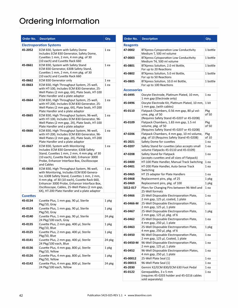
Order No. Description Qty.
Electroporation Systems45-2052 ECM 830, System with Safety Dome
Includes ECM 830 Generator, Safety Dome, Cuvettes 1 mm, 2 mm, 4 mm pkg. of 30 (10 each) and Cuvette Rack 660
1 ea
45-0661 ECM 830, System with Safety Stand ECM 830 Generator, 630B Safety Stand, Cuvettes 1 mm, 2 mm, 4 mm pkg. of 30 (10 each) and Cuvette Rack 660
1 ea
45-0662 ECM 830 Generator only 1 ea45-0663 ECM 830, High Throughput System, 25-well,
with HT-100, Includes ECM 830 Generator, 25-Well Plates (2 mm gap, 6X), Plate Seals, HT-100 Plate Handler and a plate adaptor
1 ea
45-0664 ECM 830, High Throughput System, 25-well, with HT-200, Includes ECM 830 Generator, 25-Well Plates (2 mm gap, 6X), Plate Seals, HT-200 Plate Handler and a plate adaptor
1 ea
45-0665 ECM 830, High Throughput System, 96-well, with HT-100, Includes ECM 830 Generator, 96-Well Plates (2 mm gap, 2X), Plate Seals, HT-100 Plate Handler and a plate adaptor
1 ea
45-0666 ECM 830, High Throughput System, 96-well, with HT-200, Includes ECM 830 Generator, 96-Well Plates (2 mm gap, 2X), Plate Seals, HT-200 Plate Handler and a plate adaptor
1 ea
45-0667 ECM 830, System with Monitoring Includes ECM 830 Generator, 630B Safety Stand, Cuvettes 1 mm, 2 mm, 4 mm pkg. of 30 (10 each), Cuvette Rack 660, Enhancer 3000 Probe, Enhancer Interface Box, Oscilloscope and Cables
1 ea
45-0668 ECM 830, High Throughput System, 96-well, with Monitoring, Includes ECM 830 Genera-tor, 630B Safety Stand, Cuvettes 1 mm, 2 mm, 4 mm pkg. of 30 (10 each), Cuvette Rack 660, Enhancer 3000 Probe, Enhancer Interface Box, Oscilloscope, Cables, 25-Well Plates (2 mm gap, 6X), HT-200 Plate Handler and a plate adaptor
1 ea
Cuvettes45-0134 Cuvette Plus, 1 mm gap, 90 µl, Sterile
Pkg/10, Gray1 pkg
45-0124 Cuvette Plus, 1 mm gap, 90 μl, SterilePkg/50, Gray
1 pkg
45-0140 Cuvette Plus, 1 mm gap, 90 µl, Sterile24 Pkg/100 each, Gray
24 pkg
45-0135 Cuvette Plus, 2 mm gap, 400 µl, Sterile Pkg/10, Blue
1 pkg
45-0125 Cuvette Plus, 2 mm gap, 400 μl, SterilePkg/50, Blue
1 pkg
45-0141 Cuvette Plus, 2 mm gap, 400 µl, Sterile24 Pkg/100 each, Blue
24 pkg
45-0136 Cuvette Plus, 4 mm gap, 800 μl, Sterile Pkg/10, Yellow
1 pkg
45-0126 Cuvette Plus, 4 mm gap, 800 μl, Sterile Pkg/50, Yellow
1 pkg
45-0142 Cuvette Plus, 4 mm gap, 800 µl, Sterile 24 Pkg/100 each, Yellow
24 pkg
Order No. Description Qty.
Reagents47-0002 BTXpress Cytoporation Low Conductivity
Medium T, 500 ml volume1 bottle
47-0003 BTXpress Cytoporation Low ConductivityMedium T4, 500 ml volume
1 bottle
45-0801 BTXpress Solution, 2.0 ml Bottle,For up to 20 Reactions
1 bottle
45-0802 BTXpress Solution, 5.0 ml Bottle,For up to 50 Reactions
1 bottle
45-0805 BTXpress Solution, 10.0 ml Bottle,For up to 100 Reactions
1 bottle
Accessories45-0495 Oocyte Electrode, Platinum Plated, 10 mm,
1 mm gap (Electrode only)1 ea
45-0496 Oocyte Electrode Kit, Platinum Plated, 10 mm,1 mm gap, (with cables)
1 kit
45-0110 Flatpack Chambers, 0.56 mm gap, 80 μl vol-ume, pkg. of 50 (Requires Safety Stand 45-0207 or 45-0208)
Pkg of 50
45-0109 Flatpack Chambers, 1.83 mm gap, 1.5 ml volume, pkg. of 50 (Requires Safety Stand 45-0207 or 45-0208)
Pkg of 50
47-0206 Flatpack Chambers, 4 mm gap, 10 ml volume,pkg. of 10 (Requires Safety Stand 45-0208)
Pkg of 10
45-2021 Safety Dome for cuvettes 1 ea45-0207 Safety Stand for cuvettes (also accepts small
volume Flatpacks 45-0110 and 45-0109)1 ea
47-0208 Safety Stand for Flatpack (accepts cuvettes and all sizes of Flatpack)
1 ea
45-0400 HT-100 Plate Handler, Manual Track Switching 1 ea45-0401 HT-200 Plate Handler, Auto-Sense Track
Switching1 ea
45-0465 HT 25 adapter for Plate Handlers 1 ea45-0468 Replacement pins, pkg. of 25 1 pkg45-0469 Replacement pins, pkg. of 100 1 pkg5012-017 Pliers for Changing Pins between 96-Well and
25-Well formats1 ea
45-0466 25-Well Disposable Electroporation Plate, 2 mm gap, 125 µl, coated, 1 plate
1 ea
45-0466-M 25-Well Disposable Electroporation Plate, 2 mm gap, 125 µl, 1 plate
1 ea
45-0467 25-Well Disposable Electroporation Plate, 2 mm gap, 125 µl, pkg. of 6
1 pkg
45-0462 25-Well Disposable Electroporation Plate, 4 mm gap, 250 µl, 1 plate
1 ea
45-0463 25-Well Disposable Electroporation Plate, 4 mm gap, 250 µl, pkg. of 6
1 pkg
45-0450 96-Well Disposable Electroporation Plate, 2 mm gap, 125 µl, Coated, 1 plate
1 ea
45-0450-M 96-Well Disposable Electroporation Plate, 2 mm gap, 125 µl, 1 plate
1 ea
45-0452 96-Well Disposable Electroporation Plates, 4 mm gap, 250 µl, 1 plate
1 ea
45-00012 25-Well Plate Seal (1) 1 ea45-00015 96-Well Plate Seal (1) 1 ea45-2030 Gemini X2/ECM 830/ECM 630 Foot Pedal 1 ea45-0122 Genepaddles, 3 x 5 mm
(requires 45-0203 holder and 45-0216 cables sold separately)
1 ea
Ordering Information

43 Publication 5423-025-REV 1.1 • www.btxonline.com
Order No. Description Qty.
45-0169 Genepaddles Kit, 3 x 5 mm(includes 45-0203 holder and 45-0216 cables)
1 kit
45-0123 Genepaddles, 5 x 7 mm(requires 45-0203 holder and 45-0216 cables sold separately)
1 ea
45-0170 Genepaddles Kit, 5 x 7 mm(includes 45-0203 holder and 45-0216 cables)
1 kit
45-0203 Genetrode/Genepaddle Holder 1 ea45-0117 Genetrodes, 1 mm L-Shape (GOLD TIP)
(requires 45-0203 holder and 45-0216 cables sold separately)
1 ea
45-0164 Genetrodes, 1 mm L-Shape (GOLD TIP)with 45-0203 holder and 45-0216 cables
1 kit
45-0116 Genetrodes, 3 mm L-Shape (GOLD TIP)(requires 45-0203 holder and 45-0216 cables sold separately)
1 ea
45-0163 Genetrodes, 3 mm L-Shape (GOLD TIP)with 45-0203 holder and 45-0216 cables
1 kit
45-0115 Genetrodes, 5 mm L-Shape (GOLD TIP)(requires 45-0203 holder and 45-0216 cables sold separately)
1 ea
45-0162 Genetrodes Kit, 5 mm L-Shape (GOLD TIP)with 45-203 holder and 45-0216 cables
1 kit
45-0113 Genetrodes, 5 mm Straight (GOLD TIP)(requires 45-0203 holder and 45-0216 cables sold separately)
1 ea
45-0160 Genetrodes Kit, 5 mm Straight (GOLD TIP)with 45-0203 holder and 45-0216 cables
1 kit
45-0114 Genetrodes, 10 mm Straight (GOLD TIP)(requires 45-0203 holder and 45-0216 cables sold separately)
1 ea
45-0161 Genetrodes Kit, 10 mm Straight (GOLD TIP)with 45-0203 holder and 45-0216 cables
1 kit
45-0509 Needle L-Shaped Platinum Electrode, 3mm(requires 45-0508 cables sold separately)
1 ea
45-0510 Needle L-Shaped Platinum Electrode Kit, 3 mm, with 45-0508 cables
1 kit
45-0530 Adherent Cell Electrode, 5 mm gap,For 12 well dish adherent electroporation(requires 45-0204 cables sold separately)
1 ea
45-0531 Adherent Cell Electrode, 5 mm gap,For 12 well dish adherent electroporationwith 45-0204 cables
1 kit
45-0130 Petri Pulser, 2 mm gap,For 35 mm dish adherent electroporation
1 ea
45-0100 Petri Dish Electrode, 2 mm gap,For 10 cm dish adherent electroporation
1 ea
45-0504 Petri Dish Platinum Electrode Chamber for Tissues, 5 mm gap (requires 45-0216 cables sold separately)
1 ea
45-0505 Petri Dish Platinum Electrode Chamber Kit for Tissues, 5 mm gap, with 45-0216 cables
1 kit
45-0506 Petri Dish Platinum Electrode Chamber for Tissues, 15 mm gap (requires 45-0216 cables sold separately)
1 ea
45-0513 Petri Dish Tissue Chamber Kit for Tissues, 15 mm gap, with 45-0216 cables
1 kit
45-0491 Petri Dish Platinum Electrode Chamber for Tissue Slices, 7 mm, negative
1 ea
45-0492 Platinum Electrode Wand for Tissue Slices, 7 mm, positive
1 ea
Order No. Description Qty.
45-0490 Petri Dish Platinum Electrode for Tissue Slices Chamber Kit, 7 mm, with 45-0491 chamber, 45-0492 wand 7 mm, 45-0503 cables, 45-0204 cables
1 kit
45-0501 Petri Dish Platinum Electrode Chamber for Tissue Slices, 10 mm, negative
1 ea
45-0502 Platinum Electrode Wand for Tissue Slices, 10 mm, positive
1 ea
45-0500 Petri Dish Platinum Electrode for Tissue Slices Chamber Kit, 10 mm, with 45-0501 chamber, 45-0492 wand 7 mm, 45-0503 cables, 45-0204 cables
1 kit
45-0490 Petri Dish Platinum Electrode for Tissue Slices Chamber Kit, 10 mm, with 45-0491 chamber, 45-0502 wand 7 mm, 45-0503 cables, 45-0204 cables
1 kit
45-0524 Platinum Tweezertrode, 1 mm Flat (requires 45-0204 cables sold separately)
1 ea
45-0525 Platinum Tweezertrode Kit, 1 mm Flat(includes 45-0204 cables)
1 kit
45-0486 Platinum Tweezertrode Kit, 1 mm Diameter(includes 45-0204 cables)
1 kit
45-0487 Platinum Tweezertrode Kit, 3 mm Diameter(includes 45-0204 cable)
1 kit
45-0489 Platinum Tweezertrode Kit, 5 mm Diameter(includes 45-0204 cables)
1 kit
45-0118 Stainless Tweezertrode Electrode, 7 mmDiameter (requires 45-0204 cables sold separately)
1 ea
45-0165 Stainless Tweezertrode Kit, 7 mm (includes 45-0204 cable)
1 kit
45-0488 Platinum Tweezertrode, 7 mm Diameter(includes 45-0204 cables)
1 kit
45-0119 Stainless Tweezertrode Electrode, 10 mmDiameter
1 ea
45-0166 Stainless Tweezertrode Kit, 10 mm (includes 45-0204 cable)
1 kit
45-0493 Triple Electrode Tweezertrode Kit, 3 mm (includes connection box)
1 kit
45-0494 Triple Electrode Tweezertrode Kit, 5 mm (includes connection box)
1 kit
45-0121 2-Needle Array Electrode Tips, 5 mm gap, Pkg. of 6
1 pkg
45-0206 2-Needle Array Handle, for 5mm gap tips 1 ea
45-0168 2-Needle Array Kit, 5 mm, Pkg. of 6, with Handle
1 kit
45-0120 2-Needle Array Electrode Tips, 10 mm gap, Pkg. of 6
1 pkg
45-0205 2-Needle Array Handle, for 10 mm gap tips 1 ea45-0167 2-Needle Array Kit, 10 mm, Pkg. of 6,
with Handle1 kit
45-0101 Caliper Electrode , 1.0 cm X 1.0 cm, Brass, Transdermal Delivery Applications
1 ea
45-0102 Caliper Electrode, 2.0 cm x 2.0 cm with extra 1.5 cm x 1.5 cm electrodes included, Stainless Steel, Electrochemotherapy Applications
1 ea
Ordering Information

44 Publication 5423-025-REV 1.1 • www.btxonline.com
Order No. Description Qty.
Cables & Adapters45-0087 Adaptor Set, Micrograbber to Banana Plug
Cables1 ea
45-0216 Micrograbber to Banana PlugConnection Cables, Red and Black, 10 ft(for use with microslides, genetrodes and tissue petri dish)
1 ea
45-0503 Micro-Grabber Cable for Tissue Slice Chamber and Oocyte electrode
1 ea
45-0204 Adapter Banana Plug Cables, Red and Black(for use with Tweezertrodes and L-Shaped Gentrodes Electrodes)
1 ea
45-0088 Female/Female Adapter Set for Banana Plug Cables
1 ea
45-0217 Banana to Banana Cables, Red and Black, 10 ft 1 ea
Ordering Information


