60
ST1028 Snow Thrower MTF−051058L OPERATOR’S MANUAL

ST1028Snow Thrower
MTF−051058L
OPERATOR’SMANUAL

INTRODUCTION
2MTF−051058L
Congratulations on your purchase of a Frontier Snowthrower. It has been designed, engineered and manufactured to give youthe best possible dependability and performance. However, like all mechanical products, your machine will occasionally re-quire adjustment and maintenance. This handbook should be read before operating or performing and adjustments on yourmachine.
The instructions in this Owner’s Manual are written for a person with some mechanical ability. Like most service books, notall the steps are described. Steps on how to loosen or tighten fasteners are steps anyone can follow with some mechanicalability. Read and follow these instructions before you use the unit.
Know your product:: If you understand the unit and how the unit operates, you will get the best performance. As you readthis manual, compare the illustrations to the unit. Learn the location and the function of the controls. To help prevent an acci-dent, follow the operating instructions and the safety rules. Keep this manual for future reference.
IMPORTANT: Many units are not assembled and are sold in cartons. It is the responsibility of the owner to make sure the as-sembly instructions in this manual are exactly followed. Other units are purchased in an assembled condition. On assembledunits, it is the responsibility of the owner to make sure the unit is correctly assembled. The owner must carefully check the unitaccording to the instructions in this manual before it is first used.
The warranty, found in this manual, details the coverage and limitations of this product. Registration of the warranty isnecessary and must be preformed by the dealer within sixty (60) days from the date of retail sale or delivery. TheWarranty Registration Form is located on the Frontier website.
RESPONSIBILITY OF THE OWNERThe responsibility of the owners to follow the instructions below.
1. Carefully read and follow the rules for safe operation.
2. Follow all the assembly instructions.
3. Inspect the unit.
4. Make sure that the operator of the unit knows how to correctly use all standard and accessory equipment.
5. Operate the unit only with guards, shields, and other safety items in place and working correctly.
6. Correctly adjust the unit.
7. Service the unit only with authorized or approved replacement parts.
8. Complete all maintenance on the unit.
Read And Keep This Book For Future Reference. This Book Contains Important Information On:
SAFETY, ASSEMBLY, OPERATION AND MAINTENANCE.
PRODUCT INFORMATIONThe owner must be certain that all the product information is included with this unit.
This information includes the INSTRUCTION BOOKS, the REPLACEMENT PARTSand the WARRANTIES. This information must be included to make
sure state laws and other laws are followed.
RULES FOR SAFE OPERATION
3MTF−051058L
This manual contains safety information to make youaware of the hazards and risks associated with snow
throwers, and how to avoid them. The snow thrower is designed andintended for removal of snow, and should not be used for any otherpurpose. It is important that you read and understand theseinstructions, and anyone operating the equipment read andunderstand these instructions.
The engine exhaust from this product contains chemicals known to theState of California to cause cancer, birth defects, or other reproductiveharm.
WARNING
A signal word (DANGER, WARNING, or CAUTION) is used with the alertsymbol to indicate the likelihood and the potential severity of injury. Inaddition, a hazard symbol may be used to represent the type of hazard.
DANGER indicates a hazard which, if not avoided, will result indeath or serious injury.
WARNING indicates a hazard which, if not avoided, could resultin death or serious injury.
CAUTION indicates a hazard which, if not avoided, might resultin minor or moderate injury.CAUTION, when used without the alert symbol, indicates asituation that could result in damage to the equipment.
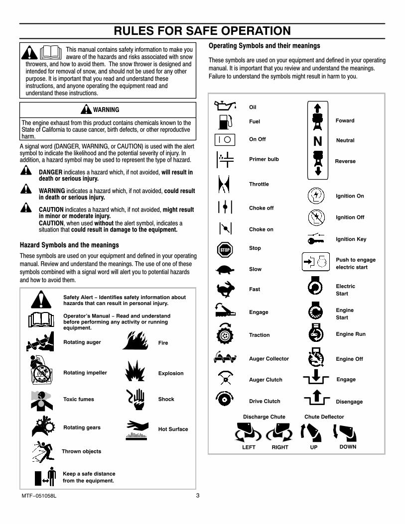
Hazard Symbols and the meanings
These symbols are used on your equipment and defined in your operating
manual. Review and understand the meanings. The use of one of these
symbols combined with a signal word will alert you to potential hazards
and how to avoid them.
Explosion
Toxic fumes Shock
Hot Surface
Fire
Operator’s Manual − Read and understandbefore performing any activity or runningequipment.
Safety Alert − Identifies safety information abouthazards that can result in personal injury.
Rotating auger
Rotating impeller
Rotating gears
Thrown objects
Keep a safe distancefrom the equipment.
Operating Symbols and their meanings
These symbols are used on your equipment and defined in your operating
manual. It is important that you review and understand the meanings.
Failure to understand the symbols might result in harm to you.
Stop
Fuel
Choke off
Oil
Choke on
Slow
Fast
On Off
Ignition Key
Ignition Off
Ignition On
Primer bulb
Throttle
Drive Clutch
Auger Clutch
Engage
RIGHT
Auger Collector
Traction
Discharge Chute
LEFT UP DOWN
Foward
Neutral
Reverse
Push to engageelectric start
ElectricStart
EngineStart
Engine Run
Engine Off
Chute Deflector
Engage
Disengage

RULES FOR SAFE OPERATION
4MTF−051058L
Avoid death or serious injury from rotating auger.
Keep hands, feet and clothing away.
Unclogging discharge chute is a hazardous activity.
• Never attempt to clear auger of debris or clogged snow while equipment isengaged or engine is running. Clogged or blocked augers store energyand can rotate unexpectedly, EVEN WITH ENGINE OFF.
• Stop engine and disconnect spark plug wire when performing maintenanceon equipment.
• Never leave the equipment unattended while engine is running. Alwaysdisengage the auger and traction controls, stop engine, and remove keys.
• Keep children, pets, and others out of the area during operation. Childrenare often attracted to the equipment. Be mindful of all persons present.
• Keep all loose clothing far away from front of snow thrower and auger.Scarfs, mittens, dangling drawstrings, loose clothes and pants can quicklybecome caught in the rotating device and dismemberment will occur. Tieup long hair and remove jewerly.
• The snow thrower is intended to remove snow only. Do not use for otherpurposes other than what is intended.
• Do not clear snow across the face of slopes. Exercise extreme caution whenchanging direction on slopes. Do not attempt to clear steep slopes.
• Do not use the snow thrower on surfaces above ground level such as roofsof residences, garages, porches or other such structures or buildings.
DANGER
Discharge chute contains rotating impeller to throw snow.Never clear or unclog discharge chute with your hands, orwhile engine is running.
Fingers can quickly become caught and traumaticamputation or severe laceration can result.
• Unclogging the discharge chute is a hazardous activity. Clogged orblocked augers store energy and can rotate unexpectedly.
• Never place hands in or near discharge chute.• With engine OFF, wait for all moving parts to cease movement, then with a
stick, clear the chute. Even with engine off, parts may rotate anddismemberment can occur.
• Clogged snow can hide other obstructions in the chute and cause damageto the equipment, impeller or auger. Take precautions when restating theequipment after snow removal.
DANGER
Objects can be picked up by auger and thrown from chute.
Never throw snow toward people or cars, and never allowanyone in front of the snow thrower.
• Be aware of your enviroment while operating equipment. Running overitems such as, gravel, doormats, newspapers, toys, and rocks hiddenunder snow, can all be thrown from chute or jam in the auger.
• Always be aware of the direction the snow is being thrown. Nearbypedestrians, pets or property may be harmed by objects being thrown.
• Familiarize yourself with the area you plan to work. Mark off boundarties ofwalkways and driveways to prevent property damage, or throwing objects.
• Take caution when snow throwing in unfamiliar areas. Stay alert for hiddenhazards and traffic.
• After striking a foreign object, turn engine OFF, wait for moving parts tocease movement, and check immediately for damage. If damaged, repairbefore starting and operating snow thrower.
• With engine OFF, wait for moving parts to stop and always use a stick toclear discharge chute.
• If unit vibrates abnormally, turn engine OFF. Vibration is generally awarning of trouble. See an authorized dealer if necessary for repairs.
DANGER
Rotating gears can contact or entangle hands, feet, hair,clothing, or accessories.
Traumatic amputation or severe laceration can result.
• Always operate equipment with all guards in place.• Keep hands and feet away from rotating gears.• Tie up long hair and remove jewelry.• Do not wear loose-fitting clothing, dangling drawstrings or items that could
become caught.
WARNING
Engines give off carbon monoxide, an odorless, colorless,poison gas.
Breathing carbon monoxide can cause nausea, fainting ordeath.
• Start and run engine outdoors.• Do not start or run engine in enclosed area, even if doors or
windows are open.
WARNING

RULES FOR SAFE OPERATION
5MTF−051058L
Gasoline and its vapors are extremely flammable and explosive.
Fire or explosion can cause severe burns or death.
WHEN ADDING FUEL
• Turn engine OFF and let engine cool at least 2 minutes before removinggas cap.
• Fill fuel tank outdoors or in well-ventilated area.• Do not overfill fuel tank.• Keep gasoline away from sparks, open flames, pilot lights, heat, and other
ignition sources.• Check fuel lines, tank, cap, and fittings frequently for cracks or leaks.
Replace if necessary.
WHEN STARTING ENGINE
• Make sure spark plug, muffler, fuel cap and air cleaner are in place.• Do not crank engine with spark plug removed.• If fuel spills, wait until it evaporates before starting engine.• If engine floods, set choke to OPEN/RUN position, place throttle in FAST
and crank until engine starts.
WHEN OPERATING EQUIPMENT
• Do not choke carburetor to stop engine.
WHEN TRANSPORTING EQUIPMENT
• Transport with fuel tank EMPTY.
WHEN STORING GASOLINE OR EQUIPMENT WITH FUEL IN TANK
• Store away from furnaces, stoves, water heaters or other appliances thathave pilot light or other ignition source because they can ignite gasolinevapors.
WARNING
Starting engine creates sparking.
Sparking can ignite nearby flammable gases.
Explosion and fire could result.
• If there is natural or LP gas leakage in area, do not start engine.• Do not use pressurized starting fluids because vapors are flammable.
WARNING
• Allow muffler, engine cylinder and fins to cool before touching.• Remove accumulated combustibles from muffler area and cylinder
area.• Install and maintain in working order a spark arrester before using
equipment on forest-covered, grass-covered, brush-coveredunimproved land. The state of California requires this (Section 4442 ofthe California Public Resources Code). Other states may have similarlaws. Federal laws apply on federal land.
WARNING
Running engines produce heat. Engine parts, especially muffler,become extremely hot.
Severe thermal burns can occur on contact.
Combustible debris, such as leaves, grass, brush, etc. can catchfire.
Unintentional sparking can result in fire or electric shock.
Unintentional start-up can result in entanglement, traumaticamputation, or laceration.
BEFORE PERFORMING ADJUSTMENTS OR REPAIRS
• Disconnect spark plug wire and keep it away from spark plug.
WHEN TESTING FOR SPARK
• Use approved spark plug tester.• Do not check for spark with spark plug removed.
WARNING

TABLE OF CONTENTS
6MTF−051058L
HAZARD SYMBOLS AND THE MEANINGS 3. . . . . . . . . . . . . . . . . . . . . . .
OPERATING SYMBOLS AND THEIR MEANINGS 3. . . . . . . . . . . . . . . . . .
SAFETY DECALS 7. . . . . . . . . . . . . . . . . . . . . . . . . . . . . . . . . . . . . . . . . . . . . .
WARRANTY 8. . . . . . . . . . . . . . . . . . . . . . . . . . . . . . . . . . . . . . . . . . . . . . . . . . .
OWNER’S INFORMATION 8. . . . . . . . . . . . . . . . . . . . . . . . . . . . . . . . . . . . . . .
ASSEMBLY 9. . . . . . . . . . . . . . . . . . . . . . . . . . . . . . . . . . . . . . . . . . . . . . . . . . . . TOOLS REQUIRED FOR ASSEMBLY 9. . . . . . . . . . . . . . . . . . . . . . . . . . . CONTENTS OF SHIPPING CARTON 9. . . . . . . . . . . . . . . . . . . . . . . . . . . PARTS BAGS CONTENTS 9. . . . . . . . . . . . . . . . . . . . . . . . . . . . . . . . . . . . UNPACKING 10. . . . . . . . . . . . . . . . . . . . . . . . . . . . . . . . . . . . . . . . . . . . . . . . . UPPER HANDLE AND CRANK ASSEMBLY 11. . . . . . . . . . . . . . . . . . . . . . CHECK THE CABLES 11. . . . . . . . . . . . . . . . . . . . . . . . . . . . . . . . . . . . . . . . . HOW TO SET THE LENGTH OF THE CABLES 11. . . . . . . . . . . . . . . . . . . REMOTE CHUTE CONTROL KNOB 12. . . . . . . . . . . . . . . . . . . . . . . . . . . . SPEED SELECT KNOB 12. . . . . . . . . . . . . . . . . . . . . . . . . . . . . . . . . . . . . . . HOW TO INSTALL THE SPEED CONTROL ROD 12. . . . . . . . . . . . . . . . . SNOW CHUTE ASSEMBLY 13. . . . . . . . . . . . . . . . . . . . . . . . . . . . . . . . . . . .
OPERATION 14. . . . . . . . . . . . . . . . . . . . . . . . . . . . . . . . . . . . . . . . . . . . . . . . . . . ENGINE AND SNOWTHROWER CONTROLS 14. . . . . . . . . . . . . . . . . . . . SNOWTHROWER OPERATION 15. . . . . . . . . . . . . . . . . . . . . . . . . . . . . . . . HOW TO SET THE DRIFT CUTTERS 16. . . . . . . . . . . . . . . . . . . . . . . . . . . BEFORE STARTING ENGINE 17. . . . . . . . . . . . . . . . . . . . . . . . . . . . . . . . . . CHECK THE OIL 17. . . . . . . . . . . . . . . . . . . . . . . . . . . . . . . . . . . . . . . . . . . . . FILL GAS 17. . . . . . . . . . . . . . . . . . . . . . . . . . . . . . . . . . . . . . . . . . . . . . . . . . . . TO STOP ENGINE 18. . . . . . . . . . . . . . . . . . . . . . . . . . . . . . . . . . . . . . . . . . . . TO START ENGINE 18. . . . . . . . . . . . . . . . . . . . . . . . . . . . . . . . . . . . . . . . . . . HOW TO CLEAR A CLOGGED DISCHARGE CHUTE 20. . . . . . . . . . . . . HOW TO USE THE CLEAN-OUT TOOL 20. . . . . . . . . . . . . . . . . . . . . . . . . OPERATING TIPS 21. . . . . . . . . . . . . . . . . . . . . . . . . . . . . . . . . . . . . . . . . . . .
SERVICE RECOMMENDATIONS 22. . . . . . . . . . . . . . . . . . . . . . . . . . . . . . . . .
MAINTENANCE 23. . . . . . . . . . . . . . . . . . . . . . . . . . . . . . . . . . . . . . . . . . . . . . . . LUBRICATION 23. . . . . . . . . . . . . . . . . . . . . . . . . . . . . . . . . . . . . . . . . . . . . . . ENGINE 25. . . . . . . . . . . . . . . . . . . . . . . . . . . . . . . . . . . . . . . . . . . . . . . . . . . . . AUGER HOUSING HEIGHT ADJUSTMENT 26. . . . . . . . . . . . . . . . . . . . . . BELT ADJUSTMENT 27. . . . . . . . . . . . . . . . . . . . . . . . . . . . . . . . . . . . . . . . . . HOW TO REPLACE THE BELTS 28. . . . . . . . . . . . . . . . . . . . . . . . . . . . . . . BELT GUIDE ADJUSTMENT 31. . . . . . . . . . . . . . . . . . . . . . . . . . . . . . . . . . . TRACTION DRIVE CABLE ADJUSTMENT 32. . . . . . . . . . . . . . . . . . . . . . . HOW TO ADJUST OR REPLACE THE FRICTION WHEEL 33. . . . . . . . . HOW TO REMOVE THE SNOW HOOD 36. . . . . . . . . . . . . . . . . . . . . . . . . AUGER SHEAR BOLT REPLACEMENT 37. . . . . . . . . . . . . . . . . . . . . . . . . TO ADJUST OR REPLACE THE SPARK PLUG 37. . . . . . . . . . . . . . . . . . .
STORAGE 38. . . . . . . . . . . . . . . . . . . . . . . . . . . . . . . . . . . . . . . . . . . . . . . . . . . . .
TROUBLE SHOOTING CHART 39. . . . . . . . . . . . . . . . . . . . . . . . . . . . . . . . . .
REPLACEMENT PARTS 40. . . . . . . . . . . . . . . . . . . . . . . . . . . . . . . . . . . . . . . . .
PARTS SCHEMATICS 41. . . . . . . . . . . . . . . . . . . . . . . . . . . . . . . . . . . . . . . . . . .
SPECIFICATIONS 60. . . . . . . . . . . . . . . . . . . . . . . . . . . . . . . . . . . . . . . . . . . . . .

SAFETY DECALS
7MTF−051058L
WARNING: If safety decals are dam-aged or missing, replace immediately.
Look for this symbol to indicate important safe-ty precautions. This symbol indicates: “Atten-tion! Become Alert! Your Safety Is At Risk.”
Before operation of your snowthrower, read the safety de-cals as shown on your snowthrower. The cautions andwarnings are for your safety. To avoid a personal injury ordamage to your snowthrower, understand and follow allsafety decals. If you have any questions regarding themeaning or how to comply with the instructions, do not op-erate until you understand the purpose for the warning ordanger given in the safety decal. If you do not understand
the meaning, then thoroughly read all safety and operationinstructions in this Owner’s Manual or contact your localdealer.
If any safety decals become worn or damaged and cannotbe read, order replacement decals from your local dealer.
Identifying Your SnowthrowerThe snowthrower has two (2) identifying numbers: (1) unitmodel number: (2) unit serial number. The two precedingnumbers are required to insure that the proper replace-ment parts are obtained when required. If you have anyquestions concerning parts, service, or technical data, con-tact the dealer where the unit was purchased.For complete warranty information refer to the warranty inthe Owner’s Information section of this manual.
Figure 1

OWNER’S INFORMATION
MTF−051058L 8
THREE YEAR LIMITED WARRANTY
Murray warrants to the original purchaser of this Frontier Branded Snowthrower that this unit shall be free from defects inmaterial and workmanship under normal use and service for a period of Three (3) Year from the date of purchase; however,this warranty does not cover accessories (such as electric starters) and Normal Wear Parts (except as noted below) as thecompanies that manufacture these items furnish their own warranties and provide service through their authorized fieldservice facilities. For additional information, see the warranties covering these particular parts. If you are uncertain whetheryour unit contains or is equipped with one or more of these parts, consult your dealer prior to purchase. Subject to the termsand conditions noted in this Limited Warranty, we shall, at our option, repair or replace at no cost to the original purchaserany part covered by this Limited Warranty during the applicable warranty period.
Normal Wear Parts are defined as drive belts, augers, shear pins, tires and headlights. These parts are warranted to be freefrom defects in material and workmanship as delivered with the product. Any claim for repair or replacement of Normal WearParts must be made within thirty (30) days of the date of purchase. No claims involving damage caused from material use,abuse or misuse will be honored.
This Murray Three (3) Year Limited Warranty for your Frontier Branded Snowthrower is your exclusive remedy; however,this warranty is void or does not apply to any unit that has been tampered with, altered, misused, abused. If used forcommercial and/or professional (non−homeowner) uses, the duration of this warranty is ninety (90) days after the date ofpurchase. Your warranty does not cover minor mechanical adjustments which are not due to any defect in material orworkmanship. For assistance in making such adjustments, consult your Operator’s Manual.
The engine on this Frontier Branded Snowthrower is warranted to the original purchaser for a Three (3) Year LimitedWarranty by the equipment manufacturer. See your engine manual for information regarding the warranty policy and itemscovered under warranty. See your authorized John Deere/Frontier Dealer for service or replacement parts.
To make a claim under this Murray Three (3) Year Limited Warranty for your Frontier Branded Snowthrower, return the unit(or if authorized in advance, the defective part) along with your proof of purchase to an Authorized John Deere/Frontier Dealernear you. To locate the nearest Authorized John Deere/Frontier Dealer, check the Yellow Page listings in your local telephonedirectory. If you return the entire unit, John Deere/Frontier will repair all warranty items. If authorize to return the defectivepart only, John Deere/Frontier will either replace or repair the part. This Murray Three (3) Year Limited Warranty for yourFrontier Branded Snowthrower gives you specific legal rights, and you may also have other rights which vary from state to
state. This Limited Warranty is given in lieu of all other expressed and implied warranties including the impliedwarranty of merchantability and warranty of fitness for a particular purpose. If you need additional information on thiswritten warranty or assistance in obtaining service, contact you local John Deere/Frontier Dealer.
MB
DATE PURCHASED:
MODEL NO:
SERIAL NO:
STORE WHERE PURCHASED:
ADDRESS:
CITY: STATE:
TELEPHONE :
Record this information about your unit so that you willbe able to provide it in case of loss or theft.
FOR YOUR RECORDS

ASSEMBLY
9MTF−051058L
TOOLS REQUIRED FOR ASSEMBLY1 − Knife2 − 1/2” wrenches (or adjustable wrenches)2 − 9/16” wrenches (or adjustable wrenches)2 − 3/4” wrenches (or adjustable wrenches)1 − 3/8” wrenches (or adjustable wrenches)1 − Pair pliers or screw driver (to spread cotter pin)
HOW TO MEASURE SCREW SIZE LENGTH
DIAMETER
CONTENTS OF SHIPPING CARTON1− Snowthrower
1− Container of Fuel Stabilizer (Located in Parts Bag)
1− Crank Assembly
1− Parts Bag
WARNING: Always wear safety glasses or eyeshields while assembling snowthrower.
PARTS BAGS CONTENTS:
1 − Shift Lever Knob(not actual size)
1 − Washer
1 − Nut
1 − Remote Chute Knob(not actual size)
1 − Ignition Keys
*2− Shear Bolt
*2− Nut* 2−Spacer
* Non Assembly parts are found in toolbox located on top of belt cover.

ASSEMBLY
10MTF−051058L
Figure 2 shows the snowthrower in the shipping position.
Figure 3 shows the snowthrower completely assembled.
Reference to right and left hand side of the snowthrower isfrom the operator’s position at the handle.
UNPACKING
1. Locate the two tear tabs at the bottom of the carton.
2. Pull the tear tape no more than twelve inches (30.48cm.)at a time. Re−grasp tape next to the carton and pullagain. Repeat until all the tape is torn off.
3. After the tape has been completely removed from thecarton, remove the carton from the base. Cut all four cor-ners and fold the sides toward the center for easy dispos-al.
4. Remove the plastic bag that covers the unit.
5. Locate and remove the parts bag.
NOTE: Set the fuel stabilizer aside until addinggasoline to the fuel tank. We recommend that fuelstabilizer is added to the fuel each time that gasolineis added to the fuel tank.
6. For shipping purposes, the height adjust skids are at-tached to the pallet. Remove the screw that secureseach height adjust skid to the pallet. (See Figure 2).
7. Roll the snowthrower off the carton by pulling on the low-er handle.
CAUTION: DO NOT back over cables.
8. Remove the packing material from the handle assembly.
9. Cut ties securing the clutch control cables to the lowerhandle.
NOTE: If the cables have become disconnected from theclutch levers, reinstall the cables as shown in Figure 4.
Figure 2
Figure 3
Auger DriveLever
Traction Drive Lever
Snow Chute Deflector
Height Adjust Skid
Auger Housing
Remote Chute Control
Screw
Speed Shifter Lever
Figure 4
”Z” Fitting
Drive Lever
Cable

ASSEMBLY
11MTF−051058L
UPPER HANDLE AND CRANK ASSEMBLY
For shipping purposes, the handles were assembledtogether with the fasteners in the LOWER holes. Whenassembled, make sure that the fasteners are in theUPPER holes and that the eye bolt is mounted in theLOWER hole on the left side as shown in Figure 5.
1. On the right side of the handle, loosen, but do not removethe fasteners (bolt, flatwasher, lockwasher and nut) thatare assembled in the lower hole.
2. On the left side of the handle, remove the fasteners (bolt,flatwasher, lockwasher and nut) that are assembled inthe LOWER holes.
3. Remove the fasteners and the crank assembly eyeboltfrom the UPPER holes of the lower handle.
4. Raise upper handle into operating position. Upper han-dle should be to the outside of the lower handle.
NOTE: Make sure the cables are not caught betweenthe upper and lower handle.
5. On the left side of the handle, install the fasteners thatwere removed in step 2. Make sure these fasteners areinstalled in the UPPER holes as shown in Figure 5.
6. Install the fasteners and the crank assembly eyebolt thatwere removed in step 3. Make sure to install the eyeboltin the LOWER holes as shown in Figure 5. DO NOT tight-en until all fasteners are in place.
7. Attach the crank rod to the universal joint assembly withthe hair pin (see Figure 6).
8. Tighten nut on eye bolt. Make sure eye bolt is properlyaligned and the crank can freely rotate.
9. Tighten all handle bolts.
NOTE: Make sure crank does not touch carburetorcover.
Figure 5
Crank
Eye Bolt
Adaptor Boot
Flatwasher
Nut
Flatwasher
Bolt
Lockwasher
Flatwasher
Locknut
Figure 6
Crank RodAssembly
Universal Joint
Hair Pin
CHECK THE CABLES
1. If control cables have become unattached from motormount frame, reconnect cables as shown in Figure 7.
2. For cable adjustments, see “How To Check And AdjustThe Cables” in the MAINTENANCE section.
HOW TO SET THE LENGTH OF THE CABLESThe cables were adjusted at the factory and no adjustmentsshould be necessary. However, after the handles are put inthe operating position, the cables can be too tight or tooloose. If an adjustment is necessary, see “How To Check AndAdjust The Cables” in the MAINTENANCE section.
Traction Drive Cable Auger Drive Cable
Figure 7

ASSEMBLY
12MTF−051058L
REMOTE CHUTE CONTROL KNOB1. Thread the knob onto the lever as far as possible. Make
sure that the knob points forward (See Figure 8).
2. Tighten the jam nut against the knob securely.
SPEED SELECT KNOB1. Thread the knob onto the lever as far as possible. Make
sure that the knob points forward (See Figure 8).
2. Tighten the jam nut against the knob securely.
Figure 8
Nut
Lever
LIp
Knob
HOW TO INSTALL THE SPEED CONTROL ROD
1. Put the speed select lever to the NEUTRAL position.See Figure 9.
2. Attach the ball joint, located on the bottom end of thespeed control rod, to the shift yoke assembly. SeeFigure 10. The fasteners (washer and nut) are in theparts bag.
3. The length ot the ball joint and speed control rod havebeen pre−adjusted at the factory. If an adjustment is re-quired, loosen the nut. Remove the fasteners to discon-nect the ball joint from the shift yoke assembly. Tolengthen or shorten the speed control rod, turn theadapter to obtain the correct length.
4. Make sure the speed select lever functions correctly.Move the speed select lever through all speeds.
Speed Select Lever
Figure 9
Remote ChuteControl Lever
Figure 10
Speed Control Rod
Nut
Adapter
Ball Joint
Shift Yoke Assembly
Fasteners

ASSEMBLY
13MTF−051058L
SNOW CHUTE ASSEMBLY
1. Remove back carriage bolt (See Figure 11).
2. Tilt chute back into operating position.
3. Replace carriage bolt from inside of chute.
4. Replace flatwasher and nylon locknut on outside offlange.
5. Tighten carriage bolt securely.
NOTE: check all carriage bolts in flange for tightness.DO NOT overtighten.
Chute DeflectorOperatingPosition
Flange
Carriage Bolt
FlatwasherLocknut
Figure 11
CHECK THE TIRES
The tires were over inflated for shipment. Check the tirepressure in the tires. See the sidewall of the tire for theproper inflation.
IMPORTANT! BEFORE YOU STARTOPERATING� Check the fasteners. Make sure all fasteners are
tight.� On electric start models, the unit was shipped with
the starter cord plugged into the engine. Beforeoperating, unplug the starter cord from the engine.
NOTE: This snowthrower was shipped WITH OIL in the engine. See “Before Starting Engine”instructions in the Operation section of this manual before starting engine.

OPERATION
14MTF−051058L
READ THIS OWNER’S MANUAL AND SAFETY RULES BEFORE OPERATING YOUR SNOWTHROWER. Compare theillustrations with your SNOWTHROWER to familiarize yourself with the location of various controls and adjustments. Savethis manual for future reference.
Figure 12
Remote Chute Control
Auger Drive Clutch LeverTraction Drive Clutch Lever
Speed Select Lever
Snow ChuteDeflector
Auger Housing
HeightAdjust Skid
Toolbox
Primer Button
Gas Fill
Starter Handle
Throttle ControlLever
Ignition Key
Choke Control
ElectricStart Button
Crank
Clean-out Tool
ENGINE AND SNOWTHROWER CONTROLSENGINE CONTROLSThrottle Control Lever − Controls the engine speed.
Choke Control− Use to start a cold engine.
Electric Start Button− Used to start the engine using the120 volt electric starter.
Prime Button− Used to inject fuel directly into carburetormanifold to insure fast starts in cool weather.
Ignition Key− Must be inserted to start engine. Pull out tostop. Do not turn ignition key.
Starter Handle− Starts the engine manually.
SNOWTHROWER CONTROLSSpeed Select Lever− Allows the operator to use one of six(6) forward and two (2) reverse speeds. To shift, move speedselect lever to desired position.
NOTE: Do not move speed select lever while TractionDrive Clutch is engaged. This may result in severedamage to drive system.
Auger Drive Clutch Lever− Used to engage and disengagethe auger and impeller. To engage push down, to disengagerelease.Traction Drive Clutch Lever− Used to propel snow blowerforward or reverse. Push down to engage, release todisengage.Snow Chute Deflector− Changes the direction the snow isblown.Remote Chute Control− Push forward to discharge snowdown. Pull back to discharge snow high and far.Crank− Used to change direction of the snow discharge.Turn handle clockwise to turn chute to right. Turn handlecounter clockwise to turn chute to left.Height Adjust Skid− Used to adjust ground clearance ofauger housing. Toolbox − Spare shear pins and spacers are located intoolbox.Clean-Out Tool − Use the clean-out tool to remove snow anddebirs from the discharge chute and the auger housing.

OPERATION
15MTF−051058L
The operation of any snowthrower can result in foreign objects being thrown into the eyes,which canresult in severe eye damage. Always wear safety glasses or eye shields before beginning snowthrowerOperation. We recommend standard safety glasses or Wide Vision Safety Mask for over spectacles.
SNOWTHROWER OPERATIONThe most effective use of the snowthrower will be establishedby experience, taking into consideration the terrain, windconditions and building location which will determine thedirection of the discharge chute.
NOTE: Do not blow snow toward a building as hiddenobjects could be blown with sufficient force to causedamage.
TO STOP YOUR SNOWTHROWER1. To stop throwing snow, release the auger drive lever.
(see Figure 13).
2. To stop the wheels, release the traction drive lever.
3. To stop the engine, push the throttle control lever to offand pull out the ignition key.
TO CONTROL SNOW DISCHARGE1. Rotate the crank to set the direction (left to right) of the
discharge chute (see Figure 12).
2. Push the remote chute lever forward to discharge thesnow down. Pull the remote chute lever back to dis-charge the snow high and far (see Figure 13).
HOW TO MOVE FORWARD AND BACKWARD1. Start the engine. See “To Start Engine” in the Operation
section.
NOTE: Always release the traction drive lever beforemoving the speed select lever.
2. Ground speed is determined by snow conditions. Set thespeed select lever in one of the following positions.
1−2 Wet, Heavy, Slushy, Extra Deep
3 Moderate
4−5 Very Light
6 Transport Only
IMPORTANT: Before operating, make sure the area infront of snowthrower is clear of bystanders orobstacles.
3. Engage the traction drive lever (see Figure 13). As thesnowthrower starts to move, maintain a firm hold on thehandles and guide the snowthrower along the cuttingpath. Do not attempt to push the snowthrower.
4. To stop forward motion, release the traction drive lever.
5. To move the snowthrower backwards, move the speedselect lever into either first or second reverse positionand engage the traction drive lever.
TO THROW SNOW1. Push down the auger driver lever (right hand). See
Figure 13.
2. To stop throwing snowl, release the auger drive lever.
NOTE: When clearing wet, heavy snow, it isrecommended that the ground speed of the unit bereduced, maintain full throttle and do not attempt toclear the full width of the unit.
For additional operating instructions see “OperatingTips” in the Operation section.
WARNING: Read Owner’s Manual before oper-ating machine. This machine can be dangerousif used carelessly.
Never operate the snowthrower without all guards,covers, and shields in place. Never direct discharge towards windows or allow by-standers near machine while engine is running. Stop the engine whenever leaving the operating posi-tion. Disconnect spark plug before unclogging the impellerhousing or the discharge chute and before making re-pairs or adjustments. When leaving the machine, remove the ignition key. To reduce the risk of fire, keep the machine clean andfree from spilled gas, oil and debris.
Auger Drive Lever
TractionDrive Lever
Speed SelectLever Remote
Chute Lever
Figure 13
WARNING: Never run engine indoors or in anenclosed, poor ventilated area. Engine exhaustcontains CARBON MONOXIDE, an OR-
DERLESS and DEADLY GAS.Keep hands, feet, hair and loose clothing away fromany moving parts on engine and snowthrower.Temperature of muffler and nearby areas can exceed150� F (66� C). Avoid these areas.DO NOT allow children or young teenagers to operateor be near snowthrower while it is operating.

OPERATION
16MTF--051058L
HOW TO USE THE WHEEL LOCKOUTEach wheel is secured to the axle with a lockout pin. SeeFigure 14. The unit was shipped with the lockout pin in thelocked position. For ease of maneuverability, disconnect thelockout pin as follows.
1. Pull the knob out to disengage the lockout pin.
2. To lock in the disengaged position, turn the knob 1/4 turn(90 degrees).
Figure 14
Knob
Wheel Lockout
HOW TO SET THE DRIFT CUTTERS
(OPTIONAL ACCESSORY ON SOME MODELS)Drift cutters are used to cut a path through snow deeper thanthe auger housing.
1. Loosen the wingnuts that secure the drift cutters to theauger housing (see Figure 15).
2. Raise the drift cutters to the desired height.
3. Tighten the wingnuts.
Drift Cutter
Wingnut
Figure 15

OPERATION
17MTF−051058L
BEFORE STARTING ENGINE
Check the oilNOTE: The engine was shipped from the factory filledwith oil. Check the level of the oil. Add oil as needed.
1. Make sure the unit is level.Use a high quality detergentoil classified “For Service SG, SH, SJ, SL, or higher”.
2. Remove the oil fill cap/dipstick and wipe with a cleancloth (see Figure 16).
3. Insert the oil fill cap/dipstick and turn clockwise to tighten.
4. Remove the oil fill cap/dipstick and check the oil.
NOTE: Do not check the level of the oil while theengine runs.
5. If necessary, add oil until the oil reaches the FULL markon the oil fill/cap dipstick (see Figure 16). Do not add toomuch oil.
6. Tighten the fill cap/dipstick securely each time you checkthe oil level.
NOTE: For extreme cold operating conditions of 0�F(−18� C) and below, use a synthetic 5W30 motor oil foreasier starting.
NOTE: S.A.E. 5W30 motor oil may be used to makestarting easier in areas where the temperature is 20� F.(−7� C) to 0�F (−18� C). Synthetic 5W30 is acceptable forall temperatures. DO NOT mix oil with gasoline.
NOTE: SEE CHART FOR OIL RECOMMENDATION
0�F (−18� C) and below
0�F (−18� C) and above
TYPE OF OILTEMPERATURE
synthetic 5W30
S.A.E. 5W30
�F − 20 0 20 32 40
�C −30 −20 −10 0 10
SAE VISCOSITY GRADES
5W30
synthetic 5W30
FILL GASThis engine is certified to operate on gasoline. ExhaustEmission Control System: EM (Engine Modifications)
1. Fill the fuel tank with fresh, clean, unleaded regular, un-leaded premium, or reformulated automotive gasolinewith a minimum of 85 octane along with a fuel stabilizer(follow instructions on fuel stabilizer package). DO NOT
use leaded gasoline. We recommend that fuel stabilizerbe added to the fuel each time that gasoline is added tothe fuel tank.NOTE: Winter grade gasoline has higher volatility toimprove starting. Be certain container is clean andfree from rust or other foreign particles. Never usegasoline that may be stale from long periods ofstorage in the container.CAUTION: DO NOT use gasoline containing anyamount of alcohol as it can cause serious damage tothe engine or significantly reduce the performance.
2. Check to make sure that spark plug is tightened securelyinto engine and spark plug wire is attached to spark plug.If torque wrench is available, torque plug to 18−23 ft−lbs.
WARNING: Gasoline is flammable. Always usecaution when handling or storing gasoline. Donot add gasoline to the fuel tank while snow
blower is running, hot, or when snow blower is in an en-closed area. Keep away from open flame, electricalsparks and DO NOT SMOKE while filling the fuel tank.Never fill the fuel tank completely; but fill the fuel tankto within 1-1/2 inch (3.8 mm) from the top to providespace for the expansion of the fuel. Always fill fuel tankoutdoors and use a funnel or spout to prevent spilling.Make sure to wipe up any spilled fuel before startingthe engine.Store gasoline in a clean, approved container, and keepthe cap in place on the container. Keep gasoline in acool well ventilated place; never in the house. Neverbuy more than a 30 day supply of gasoline to assurevolatility. Gasoline Is intended to be used as a fuel forinternal combustion engines; therefore, do not usegasoline for any other purpose. Since many childrenlike the smell of gasoline, keep it out of their reach be-cause the fumes are dangerous to inhale, as well as be-ing explosive.
FULL
Figure 16
Oil Fill Cap/DipstickFuel Tank
BEFORE STOPPING THE ENGINERun the engine for a few minutes to help dry off any moistureon the engine.

OPERATION
18MTF−051058L
TO STOP ENGINECAUTION: To stop the engine, do not move the chokecontrol to CHOKE position. Backfire or engine damagecan occur.
1. Move throttle control to SLOW, then to STOP(Figure 17).
Figure 17
Throttle Control
2. Pull out safety/ignition key (Figure 18).
Figure 18
Throttle Control
TO START ENGINEBe sure that engine has sufficient oil. Use a high qualitydetergent oil classified “For Service SG, SH, SJ, SL, orhigher”.
The snow thrower engine is equipped with a 120 volt A.C.electric starter and recoil starter. Before starting the engine,be certain that you have read the following information.
If engine floods, set the choke to the OPEN/RUN position andcrank until the engine starts.
WARNING: Rapid retraction of the starter cord(kickback) will pull your hand or arm toward theengine faster than you can let go of the starter
cord.
� When starting the engine, slowly pull the starter corduntil resistance is felt. Then, rapidly pull the startercord.
� Make sure components; such as impellors, pulleysor sprockets, are securely attached.
WARNING: The electric starter is equipped witha three−wire power cord and plug designed tooperate on 120 volt AC house hold current. The
power cord must be properly grounded at all times toavoid the possibility of electric shock which can causeinjury to the operator. Follow all instructions carefullyas set forth below:Make sure your house has a three−wire grounded sys-tem. If you are not sure, ask a licensed electrician. Ifyour house does not have a three−wire grounded sys-tem, do not use this electric starter under any condi-tion.If your house has a three−wire grounded system but athree hole receptacle is not available to connect theelectric starter, have a three−hole receptacle installedby a licensed electrician.
WARNING: To connect a 120 volt power cord,always connect the power cord first to theswitch box located on the engine and then plug
the other end into a three−hole grounded receptacle.
WARNING: To disconnect the power cord, al-ways unplug the end connected to the three−hole grounded receptacle first.
COLD ENGINE START(Engine has not been run recently.)
1. Be sure auger drive clutch lever and traction drive clutchlever are in the disengaged (RELEASED) position.
2. Move throttle control to “FAST” position. Operate the en-gine with the throttle control in FAST position (Figure 19).Before engaging auger drive clutch lever allow engine toidle for five minutes to allow engine oil to warm . Failureto allow engine oil to warm can cause damage to engine.
Figure 19
Throttle Control
3. Insert key into ignition slot. Make sure it snaps into place(Figure 20). Do not turn key.
4. Rotate choke knob to the CHOKE position.
5. Push the primer button as follows:Above 50° F (10° C), DO NOT PRIME.From 50° F (10° C) to 15°F (−10° C), PUSH TWO TIMES.Below 15° F (−10° C), PUSH FOUR TIMES.

OPERATION
19MTF−051058L
NOTE: Cover the vent hole when as you push theprimer. Remove your finger from the primer venthole between pushes.
Choke Knob
Figure 20Primer Button
Ignition Key
6. (RECOIL START) Slowly pull the recoil starter handleuntil resistance is felt and then pull repidly to start the en-gine (Figure 21). Do not allow the recoil starter handleto snap back. Slowly return the recoil starter handle.
Recoil Starter Handle
Figure 21
7. (ELECTRIC START) Connect the power cord to the en-gine and depress the starter button (Figure 22). To pro-long the life of the starter, do not crank for more than 5seconds at a time. Wait one minute between starts to al-low the starter motor to cool.
Figure 22
Starter Button
ConnectPower Cord
8. If the engine does not start in 5 or 6 tries, See DifficultStarting in the “Troubleshooting Table”.
9. As engine warms up move choke lever to “1/2 choke”position. When engine does not run smoothly, movechoke lever to the off position.
NOTE: Allow the engine to warm up for severalminutes before blowing snow in temperatures below0°F (−18� C).
10. (Electric Start) First disconnect power cord from recep-tacle. Then, disconnect the power cord from the switchbox.
If after following the preceding instructions, your engine failsto start, have the engine checked by a John Deere/Frontierdealer.
NOTE: Do not lose the safety/ignition key. Keep thesafety/ignition key is a safe place. The engine will notstart without the safety/ignition key.
WARM ENGINE START (RECOIL STARTER)If restarting a warm engine after a short shutdown, leavechoke at “OFF” and do not push the primer button. If theengine fails to start, follow the Cold Start instructions.

OPERATION
20MTF−051058L
FROZEN STARTER
If the starter is frozen and will not turn engine:
1. Pull as much rope out of the starter as possible.
2. Release the starter handle and let it snap back againstthe starter. Repeat until the engine starts.
Warm engines will cause condensation in cold weather. Tohelp prevent possible freeze−up of recoil starter and enginecontrols, proceed as follows after each snow removal job.
1. With engine off, allow engine to cool for several minutes.
2. Pull starter rope very slowly until resistance is felt, thenstop. Allow the starter rope to recoil. Repeat three times.
3. With the engine not running, wipe all snow and moisturefrom the carburetor cover in area of control levers. Alsomove choke knob and starter handle several times.
4. With engine not running, wipe all snow and moisture fromcarburetor cover in area of control levers. Also movecontrol levers backward and forward several times.
WARNING: Never run engine indoors or in en-closed, poorly ventilated areas. Engine exhaustcontains CARBON MONOXIDE, AN ODORLESS
AND DEADLY GAS. Keep hands, feet, hair and looseclothing away from any moving parts on engine andsnow thrower.� Engine parts, especially the muffler, become ex-
tremely hot. Severe thermal burns can occur on con-tact. Allow the engine to cool before touching.
� Never allow children to operate the snow thrower.Never allow adults to operate the snow blower with-out proper instruction.
� Keep the area of operation clear of all persons, partic-ularly small children and pets.
� Never leave the snow blower unattended while theengine is running. Anyone operating the engine orequipment must carefully read and understand theoperating instructions.
IMPORTANT: After each use of the snow blower, stop theengine, remove the safetey/ignition key, remove allaccumulated snow from the snow blower and wipeclean. Store the snow blower in a protected area.
NOTE: Never cover snow blower while engine andexhaust area are still warm.
HOW TO CLEAR A CLOGGED DISCHARGE CHUTE
WARNING: Hand contact with the rotating im-peller inside the discharge chute is the mostcommon cause of injury associated with snow
blowers. NEVER USE YOUR HAND TO CLEAN OUTTHE DISCHARGE CHUTE.
To Clear The Chute:� SHUT OFF THE ENGINE!� Wait 10 seconds to be sure that the impeller blades
have stopped rotating.� Always use a clean-out tool, not your hands.
A clean-out tool is attached to either the handle or the top ofthe auger housing (see Figure 23). Use the clean-out tool toremove snow from the auger housing.
How To Use The Clean-Out Tool� Release the auger drive lever.� Pull out the safety key.� Disconnect spark plug wire.� Do not place your hands in the auger or discharge
chute. Use a clean-out tool to remove snow or debris.
WARNING: Blockage must be cleared only aftershutting off the snow blower and only with aclean-out tool, not by hand.
Figure 23
Clean-out Tool

OPERATION
21MTF−051058L
OPERATING TIPS
1. For optimum snow blower efficiency, adjust groundspeed, not the throttle. REMEMBER − if the wheels slip,forward speed will be reduced. The engine is designedto deliver optimum performance at full throttle and mustbe run at this power setting at all times.
2. Most efficient snowblowing is accomplished when snowis removed immediately after it falls.
3. For complete snow removal, slightly overlap each swathpreviously taken.
4. Snow should be discharged downwind whenever pos-sible.
5. For normal usage, set the skids one−eighth inch (3 mm)below the scraper bar. For extremely hard−packed snowsurfaces, the skids may be adjusted upward to insurecleaning efficiency.
6. On gravel or crushed rock surfaces, the skids should beset at 1−1/4 inch (32 mm) below the scraper bar (see ToAdjust Skid Height, in the Adjustment/Repair section inthis manual). Rocks and gravel must not be picked upand thrown by the machine.
7. After the snowblowing job has been completed, allow theengine to idle for a few minutes, to melt snow and ice ac-cumulated on the engine.
8. Clean the snow thrower thoroughly after each use.9. Remove ice and snow accumulation and all debris from
the entire snow thrower, and flush with water (if possible)to remove all salt or other chemicals. Wipe snow throwerdry.
10. Before starting snow blower, always inspect augers andimpeller for ice accumulation and/or debris, which couldresult in snow blower damage.
11. Check oil level before every start. Make sure the oil is atthe FULL mark on the oil fill cap/dipstick.

SERVICE RECOMMENDATIONS
22MTF−051058L
SERVICE RECOMMENDATIONS
PROCEDURE
FIRST2
HOUR
BEFOREEACHUSE OFTEN
EVERY5
HOURS
EVERY10
HOURS
EVERY25
HOURS
BEGINNINGEACH
SEASONBEFORE
STORAGE
STighten all screws and nuts √ √ √
SNOW
Check Traction ClutchCable Adjustment (See Cable Adjustment)
√ √
WTH
Check Auger Clutch CableAdjustment (See Cable Adjustment)
√ √HRO
Adjust Drive Belts √ √ √OWE
Lubricate Chains and Hex Shaft √ √
ER Lubricate Auger Shaft (See
Shear Bolt Replacement) √ √
ENG
Oil, Check √ √ √GINE
Oil, Change √ √ √
The warranty on this snowthrower does not cover items thathave been subjected to operator abuse or negligence. To re-ceive full value from the warranty, operator must maintainsnowthrower as instructed in this manual. The following Ser-vice Recommendations is supplied to assist operator toproperly maintain snowthrower. This is a check list only. Ad-justment referred to will be found in the MAINTENANCE sec-tion of this manual.
AFTER EACH USE
1. Check for any loose or damaged parts.2. Tighten any loose fasteners.3. Check and maintain the auger.4. After each use, remove all snow and slush off the snow-
thrower to prevent freezing of auger or controls.5. Check controls to make sure they are functioning proper-
ly.6. If any parts are worn or damaged, replace immediately.
MAINTENANCE
23MTF−051058L
Some adjustments will need to be made periodically toproperly maintain your snowthrower.
All adjustments in the MAINTENANCE section of this manualshould be checked at least once each season.
SNOWTHROWERThe following adjustment should be performed more thanonce each season.
Auger and Traction Drive Belts should be adjusted after thefirst 2 to 4 hours of use, again about mid−season and twiceeach season thereafter (See To Adjust Belts paragraph in theMAINTENANCE section).
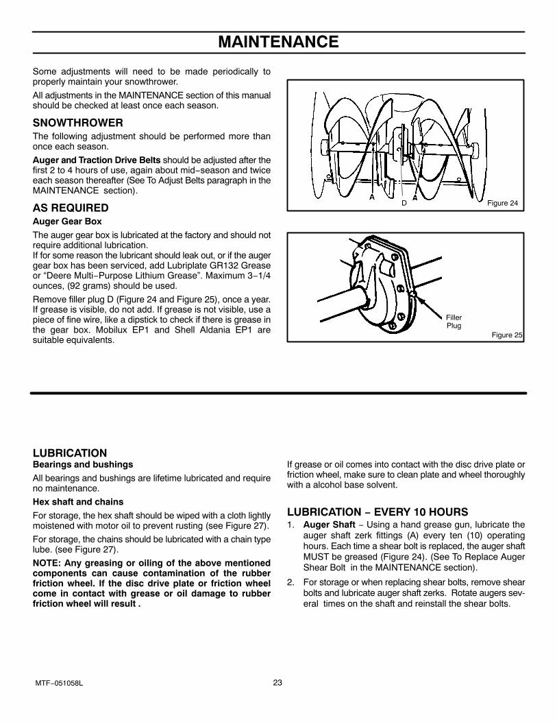
AS REQUIREDAuger Gear Box
The auger gear box is lubricated at the factory and should notrequire additional lubrication. If for some reason the lubricant should leak out, or if the augergear box has been serviced, add Lubriplate GR132 Greaseor “Deere Multi−Purpose Lithium Grease”. Maximum 3−1/4ounces, (92 grams) should be used.
Remove filler plug D (Figure 24 and Figure 25), once a year.If grease is visible, do not add. If grease is not visible, use apiece of fine wire, like a dipstick to check if there is grease inthe gear box. Mobilux EP1 and Shell Aldania EP1 aresuitable equivalents.
Figure 24D
Figure 25
FillerPlug
LUBRICATIONBearings and bushings
All bearings and bushings are lifetime lubricated and requireno maintenance.
Hex shaft and chains
For storage, the hex shaft should be wiped with a cloth lightlymoistened with motor oil to prevent rusting (see Figure 27).
For storage, the chains should be lubricated with a chain typelube. (see Figure 27).
NOTE: Any greasing or oiling of the above mentionedcomponents can cause contamination of the rubberfriction wheel. If the disc drive plate or friction wheelcome in contact with grease or oil damage to rubberfriction wheel will result .
If grease or oil comes into contact with the disc drive plate orfriction wheel, make sure to clean plate and wheel thoroughlywith a alcohol base solvent.
LUBRICATION − EVERY 10 HOURS1. Auger Shaft − Using a hand grease gun, lubricate the
auger shaft zerk fittings (A) every ten (10) operatinghours. Each time a shear bolt is replaced, the auger shaftMUST be greased (Figure 24). (See To Replace AugerShear Bolt in the MAINTENANCE section).
2. For storage or when replacing shear bolts, remove shearbolts and lubricate auger shaft zerks. Rotate augers sev-eral times on the shaft and reinstall the shear bolts.

MAINTENANCE
24MTF−051058L
LUBRICATION − EVERY 25 HOURS
Chute Rotation Gear
Lubricate the chute rotation gear with automotive type oil.(see Figure 26).
Chute Rotation Gear
Figure 26
Chains
1. Position speed selector lever in first (1) forward gear.2. Stand the snowthrower up on the auger housing end.
NOTE: When the crank case if filled with oil, do notleave the snowthrower standing up on the augerhousing for an extended period of time.
3. Remove the bottom panel.
4. Lubricate the chains with a chain type lubricant.5. Wipe the hexshaft and sprockets with 5W30 motor oil.
NOTE: Clean all excess grease or oil found on therubber friction wheel or the disc drive plate.
CAUTION: Do not allow grease or oil to contact therubber friction wheel or the disc drive plate.
6. Install the bottom panel.
Hexshaft− wipe with 5W30 motor oil be-fore storage and at the beginning of eachseason
Figure 27
Chain Chain
If grease or oil come in contact withthe disc drive plate or friction wheel,make sure to clean the plate andwheel thoroughly with a alcohol basesolvent.
WARNING: If the disc drive plateor rubber friction wheel come incontact with grease or oildamage to rubber friction wheelwill result .
MAINTENANCE
25MTF−051058L
ENGINE
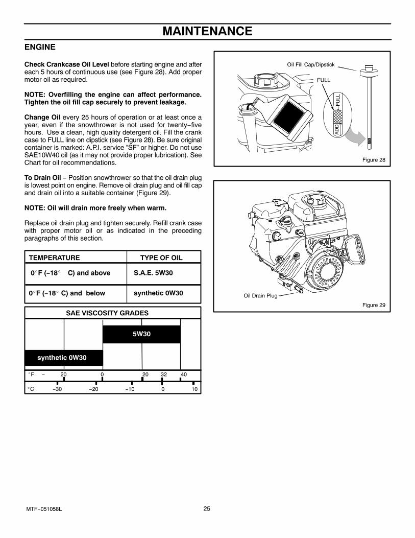
Check Crankcase Oil Level before starting engine and aftereach 5 hours of continuous use (see Figure 28). Add propermotor oil as required.
NOTE: Overfilling the engine can affect performance.Tighten the oil fill cap securely to prevent leakage.
Change Oil every 25 hours of operation or at least once ayear, even if the snowthrower is not used for twenty−fivehours. Use a clean, high quality detergent oil. Fill the crankcase to FULL line on dipstick (see Figure 28). Be sure originalcontainer is marked: A.P.I. service “SF” or higher. Do not useSAE10W40 oil (as it may not provide proper lubrication). SeeChart for oil recommendations.
To Drain Oil − Position snowthrower so that the oil drain plugis lowest point on engine. Remove oil drain plug and oil fill capand drain oil into a suitable container (Figure 29).
NOTE: Oil will drain more freely when warm.
Replace oil drain plug and tighten securely. Refill crank casewith proper motor oil or as indicated in the precedingparagraphs of this section.
0�F (−18� C) and below
0�F (−18� C) and above
TYPE OF OILTEMPERATURE
synthetic 0W30
S.A.E. 5W30
�F − 20 0 20 32 40
�C −30 −20 −10 0 10
SAE VISCOSITY GRADES
5W30
synthetic 0W30
FULL
Oil Fill Cap/Dipstick
Figure 28
Oil Drain Plug
Figure 29

MAINTENANCE
26MTF−051058L
WARNING: Always turn unit off, remove igni-tion key and disconnect the spark plug wire be-fore making any repairs or adjustments.
AUGER HOUSING HEIGHT ADJUSTMENT
TO ADJUST SCRAPER BARAfter considerable use, the metal scraper bar will have adefinite wear pattern. The scraper bar in conjunction with theskids should always be adjusted to allow one−eighth of aninch (3 mm) between the scraper bar and the sidewalk orarea to be cleaned.
To adjust the scraper bar, proceed as follows:
1. Position the snowthrower on a level surface.
2. Loosen the carriage bolts and nuts securing the scraperbar to the auger housing.
3. Adjust the scraper bar to the proper position. Tighten thecarriage bolts and nuts, insuring that the scraper bar isparallel with the working surface.
4. For extended operation, the scraper bar may be re-versed. If the scraper bar must be replaced because ofwear, remove the carriage bolts and nuts and install anew scraper bar.
TO ADJUST SKID HEIGHTThis snowthrower is equipped with two height adjust skids,secured to the outside of the auger housing. These elevatethe front of the snowthrower.
When removing snow from a hard surface area such as apaved driveway or walk, adjust the skids up to bring the frontof the snowthrower down.
When removing snow from rock or uneven construction,raise the front of the snowthrower by moving the skids down.This will help to prevent rocks and other debris from beingpicked up and thrown by the augers.
To adjust skids, proceed as follows:
1. Place a block (equal to height from ground desired) un-der scraper bar near but not under skid.
2. Loosen skid mounting nuts (Figure 30) and push the skiddown until it touches the ground. Retighten mountingnuts.
3. Set skid on other side at same height.
NOTE: Make sure that snowthrower is set at same heighton both sides.
WARNING: Be certain to maintain properground clearance for your particular area to becleared. Objects such as gravel, rocks or other
debris, if struck by the impeller, may be thrown withsufficient force to cause personal injury, property dam-age or damage to the snowthrower.
Figure 30
Skid Mounting Nuts
Height Adjust Skid

MAINTENANCE
27MTF−051058L
BELT ADJUSTMENT
Traction Drive Belt
The traction drive belt has constant spring pressure and doesnot require an adjustment. If the traction drive belt is slipping,replace the belt. See “How To Replace The Belts” in theMaintenance section.
Auger Drive Belt
If your snowthrower will not discharge snow, check thecontrol cable adjustment. If it is correct, then check thecondition of the auger drive belt. If it is damaged or loose,replace it (see Belt Replacement in this section of themanual).
1. Disconnect spark plug wire.
2. Remove screw from belt cover. Remove belt cover(see Figure 31).
3. Loosen nut on auger idler pulley and move auger idlerpulley towards belt about 1/8 inch (3 mm) (seeFigure 35).
4. Tighten nut.
5. Have someone engage auger drive clutch. Check ten-sion on belt (opposite idler pulley). Belt should deflectabout 1/2 inch (12.5 mm) with moderate pressureFigure 32). You may have to move idler pulley more thanonce to obtain the correct tension.
6. Reinstall belt cover.
7. Whenever belts are adjusted or replaced, the cables willneed to be adjusted. (See Cable Adjustment in this sec-tion of the manual).
8. Attach the spark plug wire.
Figure 31
Belt Cover
Screw
Figure 32
AugerDrive
EnginePulley
1/2 inch(12.5mm)Deflection
ImpellerPulley
IdlerPulley
Engaged

MAINTENANCE
28MTF−051058L
HOW TO REPLACE THE BELTS
The drive belts are of special construction and must bereplaced with original factory replacement belts availablefrom your nearest authorized service center.
Some steps require the assistance of a second person.
How To Remove the Auger Drive Belt
If the auger drive belt is damaged, the snow thrower will notdischarge snow. Replace the damaged belt as follows.
1. Disconnect the spark plug wire.
2. Loosen the bolts on each side of the bottom panel (seeFigure 33).
3. Remove the bottom panel.
4. Remove screw from belt cover. Remove the belt cover(see Figure 31).
5. Loosen the belt guide. Pull the belt guide away from theauger drive pulley (see Figure 35).
6. Pull the idler pulley away from the auger drive belt andslip the auger drive belt off of the idler pulley.
7. Remove the auger drive belt from the engine pulley. Toremove the auger drive belt, the engine pulley mayhave to be partially rotated.
8. Remove the top four bolts that hold together the augerhousing and the motor box. Loosen the bottom twobolts. The auger housing and the motor box can nowbe split apart for removal of the belt (see Figure 34).
9. Remove the old auger drive belt from the auger drivepulley . Replace the auger drive belt with an originalfactory replacement belt available from an authorizedservice center (see Figure 35).
10. Install the new auger drive belt onto the auger drivepulley.
NOTE: To assemble the auger housing to the mo-tor box, have someone hold the auger clutch leverin the ENGAGED position. This will move the idlerarm and pulley enough to allow the auger drivepulley to move back into position.
11. Assemble the auger housing to the motor box with thefour bolts that were removed in step 8. Tighten the bot-tom two bolts.
12. Install the auger drive belt onto the engine pulley.
13. Slip the auger drive belt under the idler pulley.
14. Adjust the auger drive belt. See “How To Adjust The Au-ger Drive Belt” in the Maintenance section.
15. Adjust the belt guide. See “How To Adjust The BeltGuide” in the Maintenance section.
16. Install the belt cover. Tighten screw (See Figure 31).
17. Check the adjustment of the cables. See “How To CheckAnd Adjust The Cables” in the Maintenance section.
18. Install the bottom panel (see Figure 33).
19. Tighten the bolts on each side of the bottom panel.
20. Connect the spark plug wire.
Figure 33
Bottom PanelBolt
Auger Housing
Bolt
Figure 34
RemoveBolts
AugerHousing
Motor Box
LoosenBolts

MAINTENANCE
29MTF−051058L
Belt Guide
Auger Drive Pulley
Idler PulleyAuger Drive Belt
Engine Pulley
Figure 35
E−Ring
Swing Plate Axle Rod
Traction Drive Spring
Traction Drive Belt
Traction Drive Belt
Engine Pulley
Traction Drive Pulley
Traction Drive Idler Pulley

MAINTENANCE
30MTF−051058L
How To Remove the Traction Drive Belt
If the snow thrower will not move forward, check the tractiondrive belt for wear or damage. If the traction drive belt is wornor damaged, replace the belt as follows.
1. Disconnect the spark plug wire.
2. Remove the auger drive belt. See “How To Remove TheAuger Drive Belt” in the Maintenance section.
3. Remove the e−ring from one end of the swing plateaxle rod. Remove the swing plate axle rod to allow thethe swing plate to pivot forward (see Figure 35).
4. Remove the traction drive spring.
5. Remove the old traction drive belt from the tractiondrive pulley and from the engine pulley. Replace thetraction drive belt with an original factory replacementbelt available from an authorized service center.
6. Install the new traction drive belt onto the tractiondrive pulley and onto engine pulley.
7. Make sure the traction drive idler pulley is properlyaligned with the traction drive belt.
8. Attach the traction drive spring.
9. Install the swing plate axle rod and secure with the e−ring removed earlier.
10. The bottom of the swing plate must be positioned be-tween the alignment tabs. Make sure the swing plateis properly secured (see Figure 36).
NOTE: If the drive will not engage after the tractiondrive belt has been replaced, then check to makesure that the swing plate is positioned between thealignment tabs.
11. Install and adjust the auger drive belt. See “How To Re-move The Auger Drive Belt” in the Maintenance section.
12. Adjust the belt guide. See “How To Adjust The BeltGuide” in the Maintenance section.
13. Install the bottom panel (see Figure 33).
14. Tighten the bolts on each side of the bottom panel.
15. Install the belt cover. Tighten screw (see Figure 31).
16. Check the adjustment of the cables. See “How To CheckAnd Adjust The Cables” in the Maintenance section.
17. Connect the spark plug wire.
Figure 36
Swing Plate
Alignment Tabs

MAINTENANCE
31MTF−051058L
BELT GUIDE ADJUSTMENT1. Remove spark plug wire.
2. Have someone engage auger drive.
3. Measure the distance between the belt guide and belt.The distance should be 1/8 inch (3.175 mm) for guide.See Figure 37.
4. If adjustment is necessary, loosen belt guide mountingbolt. Move belt guide to the correct position. Tightenmounting bolt.
5. Reinstall belt cover.
6. Reconnect spark plug wire.
HOW TO CHECK AND ADJUST THE CABLES The cables are adjusted at the factory and no adjustmentshould be necessary. If the cables have become stretchedor are sagging adjustment will be necessary.
Whenever belts are adjusted or replaced, the cables willneed to be adjusted.
1. Move clutch lever to the full forward position (just con-tacting plastic bumper). Holding cable tight, note posi-tion of fitting to hole in clutch lever.
2. The center of the “Z” fitting should be between the centreand top of the hole in the clutch lever. Adjust either theauger drive cable or the traction drive cable as follows.
Auger Drive Cable Adjustment
WARNING: Drain the gasoline outdoors, awayfrom fire or flame.
1. Remove the gas from the gas tank. Stand the snowthrower up on the front end of the auger housing.
2. Push cable through spring to expose the threaded por-tion of the cable (see Figure 38).
3. Hold square end of threaded portion with pliers and ad-just locknut in or out until correct adjustment is reached.Pull cable back through spring and connect cable.
Figure 37
Belt Guide
1/8 Inch (3.175 mm)
Auger Idler Pulley Engaged
Figure 38
CableSpring
Locknut
SquareEnd

MAINTENANCE
32MTF−051058L
Traction Drive Cable AdjustmentWARNING: Drain the gasoline outdoors, awayfrom fire or flame.
1. Remove the gas from the gas tank. Stand the snowthrower up on the front end of the auger housing.
2. Loosen the bolts on each side of the bottom panel (seeFigure 39).
3. Remove the bottom panel.4. Slide the cable boot off the cable adjustment bracket
(see Figure 40).5. Push the bottom of the traction drive cable through the
cable adjustment bracket until the “Z” hook can be re-moved.
6. Remove the “Z” hook from the cable adjustmentbracket. Move the “Z” hook down to the next adjust-ment hole.
7. Pull the traction drive cable up through the cable ad-justment bracket.
8. Put the cable boot over the cable adjustment bracket.9. To check the adjustment, depress the drive lever and
check the length of the drive spring (see Figure 41). Incorrect adjustment, the length of the drive spring is minimum 3 inches (76 mm.)maximum 3-3/8 inches (85 mm.).
10. Install the bottom panel (see Figure 39).11. Tighten the bolts on each side of the bottom panel.
Figure 39
Bottom PanelBolt
Auger Housing
Bolt
Figure 40
Cable Boot
Cable Adjustment Bracket
Traction Drive Cable
“Z” Hook
Figure 41Drive Spring
“A”

MAINTENANCE
33MTF−051058L
HOW TO ADJUST OR REPLACE THE FRICTION WHEEL
How To Check The Friction Wheel
If the snow thrower will not move forward, check the tractiondrive belt, the traction drive cable or the friction wheel. If thefriction wheel is worn or damaged, it must be replaced. See“How To Replace the Friction Wheel” in this section. If thefriction wheel is not worn or damaged, check as follows.
1. Remove the gas from the gas tank. Stand the snowthrower up on the front end of the auger housing (seeFigure 42).
WARNING: Drain the gasoline outdoors, awayfrom fire or flame.
2. Disconnect the spark plug wire.
3. Loosen the bolts on each side of the bottom panel (seeFigure 42).
4. Remove the bottom panel.
5. Position the shift speed lever in the lowest forwardspeed.
6. Note the position of the friction wheel (see Figure 43).The correct distance “A” from the right side of the fric-tion wheel to the outside of the motorbox is as follows:Tire Size Distance “A”12 and 13 inch 4-1/8” (10.5 cm.)16 inch 4-5/16” (10.95 cm.) If the friction wheel is not in the correct position, adjustas follows.
How To Adjust The Friction Wheel
1. Position the shift speed lever in the lowest forwardspeed.
2. Loosen hex jam nut on speed select rod. Remove balljoint from shifter rod (see Figure 44).
3. Move the friction wheel to the correct position (seeFigure 43).
4. Turn the adaptor until the ball joint is aligned with themounting hole in the shifter rod (see Figure 44). Whenaligned, attach the ball joint to the shifter rod.
5. Tighten the jam nut.
6. Install the bottom panel (see Figure 42).
7. Tighten the bolts on each side of the bottom panel.
Figure 42
Bottom PanelBolt
Bolt
Auger Housing
“A”
Figure 43
Figure 44
Shifter Rod
Ball Joint
Speed Select Rod
Jam Nut
Adaptor
Fasteners

MAINTENANCE
34MTF−051058L
How To Replace The Friction Wheel
If the friction wheel is worn or damaged, the snow thrower willnot move forward. The friction wheel must be replaced asfollows.
1. Remove the gas from the gas tank. Stand the snowthrower up on the front end of the auger housing (4).(see Figure 42).
WARNING: Drain the gasoline outdoors, awayfrom fire or flame.
2. Disconnect the spark plug wire.
3. Remove the fasteners that secure the left wheel. Re-move the left wheel from the axle (see Figure 45)
4. Loosen the bolts on each side of the bottom panel.
5. Remove the bottom panel.
Figure 45Wheel
Axle Bolt
Bolt
Bottom Panel
6. Remove the fasteners that secure the drive sprocket tothe axle (see Figure 46).
7. Remove the right wheel, axle, and drive sprocket.
Figure 46
Axle
DriveSprocket
Chain
8. Remove the four bolts that hold the bearings on eachside of the hex shaft (see Figure 47).
9. Remove the hex shaft and bearings.
NOTE: Take special note of the position of thewashers on the hex shaft.
Figure 47
Bolts
Bolts
Bearings
Hex Shaft

MAINTENANCE
35MTF−051058L
10. Remove the three fasteners that hold the friction wheelto the hub (see Figure 48).
11. Remove the friction wheel from the hub. Slip the fric-tion wheel off the hex shaft.
12. Assemble the new friction wheel onto hub with the fas-teners removed earlier.
Figure 48
Hex Shaft
Fasteners Friction
WheelHub
Fasteners
13. Install the hex shaft and bearings with the four bolts re-moved earlier (see Figure 49).
Make sure the washers are properly installed in theoriginal position. Also, make sure the two washersare properly aligned with the actuator arms.
14. Make sure the hex shaft turns freely.
Washer
Figure 49
Hex ShaftActuator Arms
Washer
Bearings
Washer
Bearings
Washer
15. Install the right wheel, axle, and drive sprocket with thefasteners removed earlier. Install the chain onto thedrive sprocket (see Figure 46).
16. Check the adjustment of the friction wheel. See “How ToAdjust The Friction Wheel” in this section.
17. Make sure the friction wheel and the disc drive plate arefree from grease or oil.
18. Install the bottom panel (see Figure 45).
19. Tighten the bolts on each side of the bottom panel.
20. Install the left wheel to the axle with the fasteners re-moved earlier.
21. Connect the spark plug wire.

MAINTENANCE
36MTF−051058L
HOW TO REMOVE THE SNOW HOOD
To access the spark plug, the snow hood must be removedas follows:
1. Remove the choke control knob (see Figure 50).
2. Remove the ON/OFF key.
3. Remove the four mounting screws.
4. Slowly remove the snow hood (see Figure 51). Makesure that the primer button hose and the ignition wire arenot disconnected.
5. To install the snow hood, first make sure that the primerbutton hose and the ignition wire are connected.
6. Mount the snow hood to the engine and secure with thefour mounting screws (see Figure 52).
7. Align the tab on the choke control knob with the slot in thesnow hood (see Figure 53).
8. Connect the choke control knob with the choke shaft.Make sure the choke control knob is properly installed.If the choke control knob is not installed correctly, thechoke will not operate.
Figure 50
Choke Control Knob
Screws
Screws
Snow Hood
ON/OFFKey
Figure 51Snow Hood
Figure 52Snow Hood
Carburetor
Choke ControlKnobTab
Slot
Figure 53
MAINTENANCE
37MTF−051058L
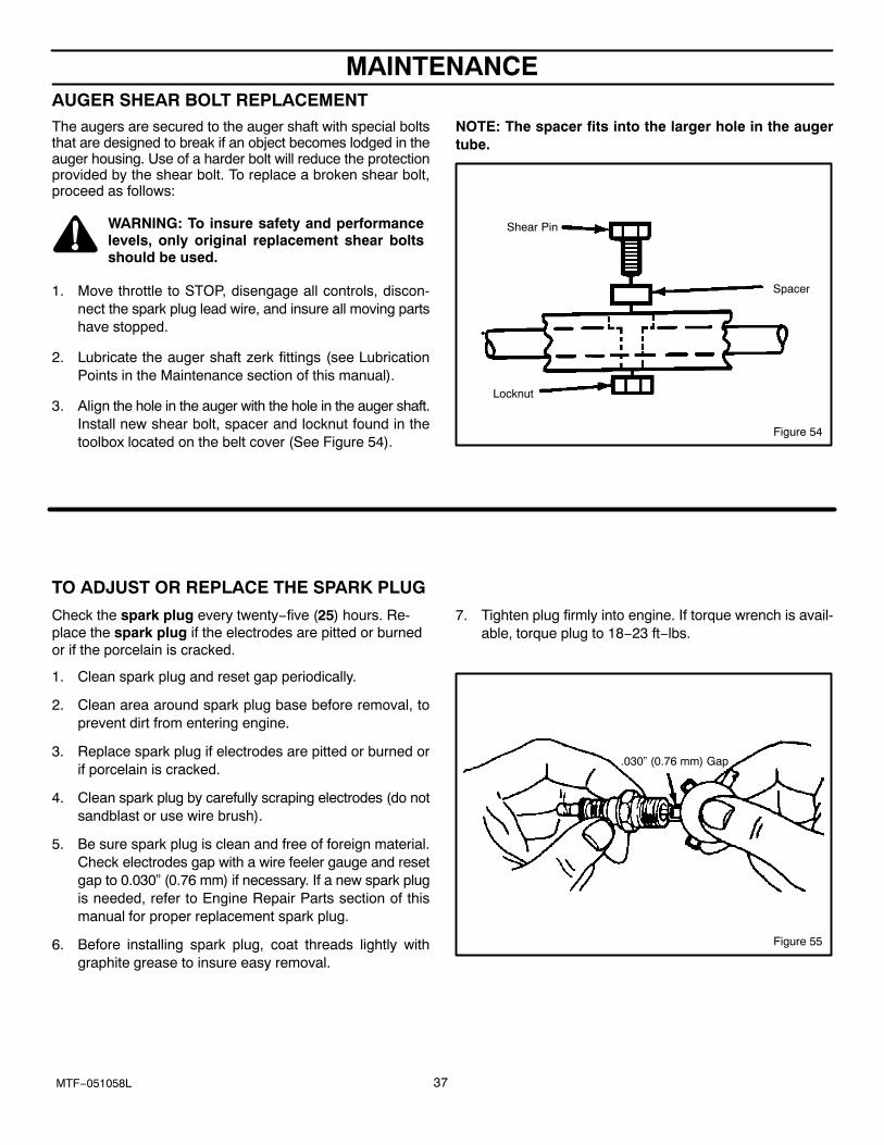
AUGER SHEAR BOLT REPLACEMENTThe augers are secured to the auger shaft with special boltsthat are designed to break if an object becomes lodged in theauger housing. Use of a harder bolt will reduce the protectionprovided by the shear bolt. To replace a broken shear bolt,proceed as follows:
WARNING: To insure safety and performancelevels, only original replacement shear boltsshould be used.
1. Move throttle to STOP, disengage all controls, discon-nect the spark plug lead wire, and insure all moving partshave stopped.
2. Lubricate the auger shaft zerk fittings (see LubricationPoints in the Maintenance section of this manual).
3. Align the hole in the auger with the hole in the auger shaft.Install new shear bolt, spacer and locknut found in thetoolbox located on the belt cover (See Figure 54).
NOTE: The spacer fits into the larger hole in the augertube.
Figure 54
Shear Pin
Locknut
Spacer
TO ADJUST OR REPLACE THE SPARK PLUG
Check the spark plug every twenty−five (25) hours. Re-place the spark plug if the electrodes are pitted or burnedor if the porcelain is cracked.
1. Clean spark plug and reset gap periodically.
2. Clean area around spark plug base before removal, toprevent dirt from entering engine.
3. Replace spark plug if electrodes are pitted or burned orif porcelain is cracked.
4. Clean spark plug by carefully scraping electrodes (do notsandblast or use wire brush).
5. Be sure spark plug is clean and free of foreign material.Check electrodes gap with a wire feeler gauge and resetgap to 0.030” (0.76 mm) if necessary. If a new spark plugis needed, refer to Engine Repair Parts section of thismanual for proper replacement spark plug.
6. Before installing spark plug, coat threads lightly withgraphite grease to insure easy removal.
7. Tighten plug firmly into engine. If torque wrench is avail-able, torque plug to 18−23 ft−lbs.
Figure 55
.030” (0.76 mm) Gap
STORAGE
38MTF−051058L
OFF SEASON STORAGE
WARNING: Never store the engine, with fuel inthe tank, indoors or in a poor ventilated enclo-sure where fuel fumes could reach an open
flame, spark or pilot light as on a furnace, water heater,clothes dryer, etc.Handle gasoline carefully. It is highly flammable andcareless use could result In serious fire damage to yourperson and /or property.Drain fuel into approved containers outdoors, awayfrom open flame.
If the snowthrower is to be stored for thirty (30) days or moreat the end of the snow season, the following steps arerecommended to prepare your snowthrower for storage.
NOTE: Gasoline must be removed or treated to preventgum deposits from forming in the tank, filter, hose, andcarburetor during storage.
1. To remove gasoline, run engine until tank is empty andengine stops.
If you do not want to remove the gasoline, add fuel stabilizerto any gasoline left in the tank to minimize gum deposits andacids. If the tank is almost empty, mix stabilizer with freshgasoline in a separate container and add some to the tank.ALWAYS FOLLOW INSTRUCTIONS ON STABILIZERCONTAINER. THEN RUN ENGINE AT LEAST 10 MINUTESAFTER STABILIZER IS ADDED TO ALLOW MIXTURE TOREACH CARBURETOR. STORE SNOWTHROWER INSAFE PLACE.
2. You can help keep your engine (4−cycles only) in goodoperating condition by changing oil before storage.
3. Lubricating the piston/cylinder area. This can be done byfirst removing the spark plug and squirting clean engineoil into the spark plug hole. Then cover the spark plughole with a rag to absorb oil spray. Next, rotate the engineby pulling the starter two or three times. Finally, reinstallspark plug and attach spark plug wire.
4. Thoroughly clean the snowthrower.
5. Lubricate all lubrication points (see “Lubrication“ in theMaintenance section).
6. Insure that all nuts, bolts, and screws are securely fas-tened. Inspect all visible moving parts for damage,breakage, and wear. Replace if necessary.
7. Touch up all rusted or chipped paint surfaces; sand lightlybefore painting.
8. Cover the bare metal parts of the blower housing auger,and the impeller with rust preventative.
9. If possible, store your snowthrower indoors and cover itto give protection from dust and dirt.
10. On models with folding handles, loosen the knobs thatsecure the upper handle. Rotate the upper handle back.
11. If the machine must be stored outdoors, block up the s-nowthrower and insure the entire machine is off theground. Cover the snowthrower with a heavy tarpaulin.
REMOVING THE SNOWTHROWER FROMSTORAGEWhen removing the snowthrower from storage, follow thesteps below.
1. Put the upper handle in the operating position, tighten theknobs that secure the upper handle.
2. Fill the fuel tank with a fresh fuel.
3. Check the spark plug. Make sure the gap is correct. If thespark plug is worn or damaged, replace before using.
4. Make sure all fasteners are tight.
5. Make sure all guards, shields, and covers are in place.
6. Make sure all adjustments are correct.

TROUBLE SHOOTING CHART
39MTF−051058L
PROBLEM LOOK FOR REMEDY
Difficult starting Defective spark plug. Replace defective spark plug.
Engine runs erratically Blocked fuel line. Clean fuel line.
Empty gas tank. Check fuel supply,
Stale gasoline. Add fresh gasoline with fuel stabilizer.
Water or dirt in fuel system. Remove carburetor bowl to drain fuel tank. Refillwith fresh fuel. CAUTION: Do not removecarburetor bowl when the engine is hot.
Engine stalls Unit running on CHOKE. Set choke lever to RUN position.
Loss of power Gas cap vent hole is plugged. Remove ice and snow from cap. Be sure venthole is clear.
Excessive vibration Loose parts or damaged impeller. Stop engine immediately and remove spark plugwire. Tighten all bolts and make all necessaryrepairs. If vibration continues, have the unitserviced by a competent repairman.
Unit fails to propelitself
Drive belt loose or damaged. Replace drive belt. Refer to Drive BeltReplacement in the Maintenance section of thismanual.
Incorrect adjustment of traction drivecable.
Adjust traction drive cable. Refer to CableAdjustment in the Maintenance section of thismanual.
Worn or damaged friction disc. Replace friction disc. Refer to Friction WheelReplacement in the Maintenance section of thismanual.
Unit fails to dischargesnow
Auger drive belt loose or damaged. Replace or adjust auger drive belt. Refer to DriveBelt Replacement and Drive Belt Adjustment inthe Maintenance section of this manual.
Auger control cable not adjustedcorrectly.
Adjust auger control cable. Refer to CableAdjustment in the Maintenance section of thismanual.
Broken shear bolt. Replace shear bolt. Refer to Auger Shear BoltReplacement in the Maintenance section of thismanual.
Discharge chute clogged. Stop engine immediately and disconnect sparkplug wire. Refer to the first Warning in Snowblower Operation in the Operation section ofthis manual. Clean discharge chute and inside ofauger housing.
Foreign object lodged in auger. Stop engine immediately and disconnect sparkplug wire. Refer to the third Warning in Snowblower Operation in the Operation section ofthis manual. Remove object from auger.
Identifying Your Snow blowerYour new Snow blower has two (2) identifying numbers: (1) unit model number: (2) unit serial number. The two precedingnumbers are required to insure that the proper replacement parts are obtained when required. If you have any questionsconcerning parts, service, or technical data, contact your nearest John Deere/Frontier dealer.For complete warranty information refer to the warranty in the Owner’s Information section of this manual.

REPLACEMENT PARTS
40MTF−051058L
WE RECOMMEND JOHN DEERE/FRONTIER qualityparts and lubricants available at your John Deere/Frontierdealer.
PART NUMBERS MAY CHANGE. When you order re-placement parts, use the part numbers listed below and onthe following pages. If a part number changes, your JohnDeere/Frontier dealer will have the latest part number.
WHEN YOU ORDER PARTS, your John Deere/Frontierdealer must have your snowthrower model and serial num-ber and your engine model number. This is the model andserial number that you recorded in the “Owner’s Informa-tion” section of this Owner’s Manual.
QUICK REFERENCE PART NUMBERS
The following is a list of replacement parts that you mayneed for routine service and maintenance. If you do notsee the replacement part you need in the following chart,then check the full list of replacement part illustrations fol-lowing this page.
ITEM PART NUMBER *
Belt, Drive MT579932
Belt, Auger MT585416
Scraper Blade MT583043E701
Spark Plug Champion RC12YC
* Part Numbers are subject to change without notice.

FRONTIER MODEL ST1028 FACTORY MODEL 628102x16A
41MTF−051058L
ENGINE
ÁÁÁ
25−1
2
3
25−4
25−2
25−3
5
4
20
22
24
10
6
7
8
11
Ref.Drive Page
Ref. AugerHousing Page
9
25−2
16
17
18
1413
15
12
1
27
28
26
Key No. Part No. Description Key No. Part No. Description1 MT6219 CORD, STARTER
2 − − − − − ENGINE
3 MT002x97 BOLT, CARRIAGE
4 MT028x76 RETAINER, PUSH
5 MT710026 NUT
6 MT1501109 PULLEY, ENGINE
7 MT17x170 WASHER
8 MT71063 WASHER
9 MT71015 SCREW
10 MT579932 BELT, DRIVE V 4L
11 MT585416 BELT, AUGER V 3L
12 MT1501112 YZ BRACKET ASSEMBLY, IDLER13 MT1501065 BUSHING, IDLER BRACKET14 MT71060 WASHER, SPLIT15 MT710097 SCREW 5/16−24 X .75
16 MT53704 SPRING, IDLER TRACTION DRIVE17 MT1502120 PULLEY, IDLER18 MT590 NUT, JAM 3/8−1620 MT1501201 GUIDE, ROD BELT
22 MT71060 WASHER
24 MT710097 SCREW
25 − − − − − − FRAME ASSEMBLY
25−1 MT1501062E511 PLATE, ENGINE
25−2 MT310169 SCREW
25−3 MT25x020 SCREW
25−4 MT1501049E511 MOTOR BOX
26 MT1501214 KEY, BRIGGS ENGINE
27 MT226462 DEFLECTOR, MUFFLER
28 MT810140 SCREW
−− MTF−051058L OWNER’S MANUAL

FRONTIER MODEL ST1028 FACTORY MODEL 628102x16A
42MTF−051058L
FRAME
162167
167
162
91
91
122
90168
103
106105
108
Ref. Engine Page
110 148
149107
Ref. DrivePage
Ref. AugerHousing Page
111
169
160
123

FRONTIER MODEL ST1028 FACTORY MODEL 628102x16A
43MTF−051058L
FRAME
Key No. Part No. Description
90 MT1501055E701 COVER, BOTTOM
91 MT310169 SCREW, 1/4−20X .63
103 MT1501369 YZ IDLER ASSEMBLY, AUGER
105 MT711682 PIN, HAIR .38DIAX1.64LG
106 MT761761 PIN, CLEVIS 3/16” DIA
107 MT165x159 SPRING, TENSION
108 MT761675 YZ ASSY., SPRING ATTACH
110 MT585781 BOLT, 3/8−16X1.25 CARR.
111 MT711617 WASHER, FLAT
122 MT25x020 SCREW, TAP 5/16−18 X .50
123 MT25x021 SCREW, TAP 5/16−18 X .75
148 MT1502120 PULLEY, IDLER
149 MT590 NUT, JAM 3/8−16
160 MT1502182 COVER, BELT
162 MT26x306 SCREW, TAP
167 MT71067 WASHER, FLAT
168 MT1501200 SPACER, AUGER BRACKET
169 MT760539 LID, TOOL BOX

FRONTIER MODEL ST1028 FACTORY MODEL 628102x16A
44MTF−051058L
DRIVE
Ref. Wheel Page
229
200
223
225
226
227
234
230
221
Ref. Wheel Page
Ref. Handle Page
206
201
203204
232
234
229
220
220
218
218
207215
215
238
238
210
212
213
213217
213
203204
236
Ref. Frame Page
Ref. WheelPage
Ref. WheelPage
208

FRONTIER MODEL ST1028 FACTORY MODEL 628102x16A
45MTF−051058L
DRIVE
Key No. Part No. Description
200 MT1501092 YZ LF AXLE, SWING PLATE YZ
201 MT579851 CHAIN, ROLLER #420x19.00
203 MT334163 BEARING AND RETAINER, ASSY
204 MT579858 WASHER
206 MT25x020 SCREW, TAP 5/16−18x0.5
207 MT1501100 ASSY, HEX SHAFT
208 MT579868 CHAIN, ROLLER #420x18.00 LG
210 MT337029 BEARING, TRUNION CLUTCH R
212 MT1501435 WHEEL, FRICTION DISC
213 MT001x38 BOLT
215 MT303008 NUT, KEPS HEX 1/4−20
217 MT579859 RING, RETEXT
218 MT579858 WASHER
220 MT334163 BEARING AND RETAINER, ASSY
221 MT25x020 SCREW, TAP 5/16−18 x .5
223 MT1501115 FRICTION PULLY
225 MT1501057 YZ LF PLATE, SWINGING YZ
226 MT1501158 SPACER, FRICTION PULLEY
227 MT15X114 NUT, FLANGE LOCK 3/8−24
229 MT11X30 RETAINER, RING
230 MT1501107 YZ LF ASSY, SPRING LINK YZ
232 MT11X30 RETAINER, RING
234 MT165X112 SPRING, EXTENSION
236 MT1501090 SPROCKET 33/7
238 MT71074 WASHER, FLAT

FRONTIER MODEL ST1028 FACTORY MODEL 628102x16A
46MTF−051058L
AUGER HOUSING
500
527
480 485
499
482
490
491
493
527
522
522
523
521
525
525
523
524
524
520
510
541
Ref. Gear Case Page
540
514
544
511
484
550
551
552
553
554

FRONTIER MODEL ST1028 FACTORY MODEL 628102x16A
47MTF−051058L
AUGER HOUSING
Key No. Part No. Description
480 MT583146 PULLEY, 4L 8.40 OD
482 MT2001022 KEY, SQUARE 3/16 X 3/4
484 MT15x112 NUT, 1/2−20
485 MT1501158 SPACER, FRICTION PULLEY
490 MT582957 YZ RETAINER, BALL BRNG
491 MT1501389 BEARING, BALL
493 MT001X92 BOLT, HEX 5/16−18X .50
499 MT710026 NUT, 5/16−18 HEXWDFLLK
500 MT1501590E511 HOUSING, ASSY
510 MT583043E701 BLADE, SCRAPER
511 MT001x45 BOLT, 5/16−18x.62
514 MT710026 NUT, 5/16−18
520 MT760597E701 AUGER, ASSY, LH
521 MT760598E701 AUGER, ASSY, RH
522 MT9524 SCREW, 1/4−20 X 1.75
523 MT3943 SPACER, SLEEVE
524 MT73826 NUT, 1/4−20
525 MT53757 BEARING, FLANGE
527 MT25x201 SCREW, 5/16−18X .75
540 MT1502187E701 SKID, HEIGHT ADJUST
541 MT908156 BOLT, 5/16−18 X .50
544 MT710026 NUT, 5/16−18
550 MT1501576 BRUSH, CLEANOUT
551 MT1501672 CLIP, RETAINER
552 MT06x115 SCREW
553 MT15x146 NUT
554 MT578063 BLOCK
− − MT1501216 KIT, SHEAR BOLT

FRONTIER MODEL ST1028 FACTORY MODEL 628102x16A
48MTF−051058L
GEAR CASE
326
320
321322
323
324
327
330
311312
306
310
304301
303
310 300
314
311
312315
313
316
340
305
Key No. Part No. Description Key No. Part No. Description300 MT896 CASE, GEAR, RH
301 MT895 CASE, GEAR, LH
303 MT910828 SCREW, 5/16−24 x 1.00
304 MT71100 NUT, 5/’16−24
305 MT330434 SCREW, 5/16−24 x 1.50
306 MT53749 PLUG, PIPE 0.25−18
310 MT780151 SEAL, OIL
311 MT53743 BEARING, SLEEVE
312 MT53748 WASHER, FLAT
313 MT584515 SHAFT, AUGER OUTPUT
314 MT897 GASKET, GEAR BOX
315 MT53730 WORM GEAR
316 MT73905 KEY, WOODRUFF #91
320 MT53737 RING, QUAD 0.924 ID
321 MT583126 BEARING, FLANGE
322 MT48275 WASHER, FLAT
323 MT50684 BEARING, ROLLER
324 MT48275 WASHER, FLAT
326 MT50795 KEY
327 MT53732 WORM
330 MT53731 BEARING, SLEEVE
340 MT1501147E701 IMPELLER
−− MT333431 10oz TUBE LUBRIPLATE

FRONTIER MODEL ST1028 FACTORY MODEL 628102x16A
49MTF−051058L
REMOTE CONTROL
975Ref. Engine Mount Bolt
981
974
965
Ref. Upper Chute
972
971
Ref. Lower Chute
968 970
969967
973
995
994
Ref. Control Panel
975
980
Key No. Part No. Description Key No. Part No. Description965 MT318468 TENSION SPRING
967 MT310088 BOLT, SHOULDER
968 MT73787 FLATWASHER
969 MT15x143 NUT
970 MT313676 SCREW, 5/16−18 X 0.75
971 MT306447 YZ BRACKET, CABLE CHUTE
972 MT71391 NUT, 5/16−18
973 MT1001221 TRIM STRIP, BLACK
974 MT071372 TIE, CABLE
975 MT1501393 CABLE, CHUTE DEFLECTOR
980 MT313676 SCREW
981 MT780220 WIRE FORM, CHUTE CABLE
994 MT71045 NUT, 3/8−16
995 MT306689 KNOB, SHIFT

FRONTIER MODEL ST1028 FACTORY MODEL 628102x16A
50MTF−051058L
DISCHARGE CHUTE
580
586587
584582
586
600
602
603601
610
609
606
611
607
585
Ref. Auger Housing Page
607
604
Pop Rivets
583

FRONTIER MODEL ST1028 FACTORY MODEL 628102x16A
51MTF−051058L
DISCHARGE CHUTE
Key No. Part No. Description
580 MT761168E701 CHUTE, UPPER W/REMOTE
582 MT578088 SCREW, 5/16−18 X.75
583 MT12021 PLASTIC WASHER
584 MT71038 NUT
585 MT578088 SCREW, 5/16−18 X.75
586 MT6711 PLASTIC WASHER
587 MT71038 NUT
600 MT761169E701 CHUTE, LOWER W/REMOTE
601 MT2x100 BOLT
602 MT71071 WASHER, FLAT
603 MT71038 NUT
604 MT762322 FLAP
606 MT1501932 YZ CHUTE COLLAR
607 MT02x101 BOLT
609 MT15x145 NUT
610 MT337227 RETAINER, RING INNER
611 MT1501282 RETAINER, RING OUTER

FRONTIER MODEL ST1028 FACTORY MODEL 628102x16A
52MTF−051058L
HANDLE
774773
772
785
729
804
770
798
803 802
787
739
771
720
790
801795
800801
791
796
799
741
724740
725724
728
727
726
751
813
811
812
809
810
759
745 762
760
Ref. EnginePage
743
765
765
751727
726725
753
739
725
729
745
806
805
808
750
763
744

FRONTIER MODEL ST1028 FACTORY MODEL 628102x16A
53MTF−051058L
HANDLE
Key No. Part No. Description Key No. Part No. Description
720 MT1501421E701 ASSY, HANDLE
724 MT7288 SCREW
725 MT71072 WASHER, FLAT
726 MT71062 WASHER
727 MT71044 NUT
728 MT7289 STOP, PLASTIC
729 MT337399 GRIP, HANDLE
739 MT4049 BUMPER
740 MT1501451 CABLE, AUGER CLUTCH
741 MT1501452 CABLE, DRIVE
743 MT313441 BRKT, CABLE ADJ
744 MT1673 SPRING, CLUTCH
745 MT15x145 NUT, HEX
750 MT1501449E701 HANDLE, LOWER
751 MT25x021 SCREW
759 MT579860 SPOOL, CABLE
760 MT1501059 YZ BRKT, SPOOL
762 MT1501122 CABLE, LOWER DRIVE
763 MT001798 BOLT, HEX 1/4−20 x 1.5
765 MT308146 BOOT, CABLE
770 MT1501570 YZ BRACKET, SHIFT
771 MT4058 SCREW
772 MT50786 SPRING
773 MT71072 WASHER, FLAT
774 MT71046 NUT, HEX
785 MT71045 NUT, HEX
787 MT306689 KNOB, SHIFT
790 MT578926 ROD, ASSY LH
791 MT578924 ROD, ASSY RH
795 MT579002 BRACKET, CAM
796 MT002x53 SCREW
798 MT71038 NUT, NYLOCK
799 MT8417 CAM LOCK
800 MT584673 PIN, SPRING PIVOT
801 MT73664 NUT, PUSH ON
802 MT71081 PIN, COTTER
803 MT71071 FLATWASHER
804 MT1501728 ROD, SPEED CONTROL
805 MT71042 NUT, 5/16−18
806 MT6352 ADAPTER, ROD
808 MT50782 BALLJOINT, STEEL
809 MT71060 WASHER
810 MT71042 NUT, 5/16−18
811 MT579944 BEARING, FL
812 MT1501110 YZ ROD, YOKE
813 MT11X30 RETAINER, RING

FRONTIER MODEL ST1028 FACTORY MODEL 628102x16A
54MTF−051058L
CHUTE ROD / GOULOTTE TIGE
856
855
854
855
861
860
863
864
864867
Ref. Handle Assy
869
852−5
852−11
852−9
852−8
852−3
868
852−13
852−10
852−1
852−2
852−6
870
Ref. Auger Housing Assy
862
852−12
865

FRONTIER MODEL ST1028 FACTORY MODEL 628102x16A
55MTF−051058L
CHUTE ROD
Key No. Part No. Description
852−1 MT1501533 YZ ASSEMBLY, YOKE & ROD
852−2 MT164x37 SPRING
852−3 MT1501067 GEAR, CHUTE ROTATION 9T
852−5 MT579493 PIN, COTTER
852−6 MT1501306E701 BRACKET, CHUTE GEAR
852−7 MT1501293 PIN, HAIR
852−8 MT1501075 YZ ASSEMBLY, YOKE ADAPTER YZ
852−9 MT711682 PIN, HAIR
852−10 MT578060 PIN, UNIVERSAL JOINT
852−11 MT578309 PIN, CLEVIS
852−13 MT578063 HOUSING, UNIVERSAL
854 MT307399 KNOB, SLEEVE
855 MT309312 FLATWASHER
856 MT73664 NUT, PUSH ON 3/8”
860 MT1501456 EYE BOLT 3/8−16X6.50
861 MT148 GROMMET, EYE BOLT
862 MT1501457 BOOT, EYE BOLT
863 MT71045 NUT, 3/8−16 HEXJAM
864 MT71072 FLATWASHER .406X.81X.066
865 MT309344 ADAPTER, BOOT
867 MT71046 NUT, 3/8−16 HEXNYL
868 MT02x101 BOLT, CARRIAGE 1/4−20 X 0.75
869 MT15x145 NUT, 1/4−20
870 MT1501074 YZ CRANK, ASSY CHUTE

FRONTIER MODEL ST1028 FACTORY MODEL 628102x16A
56MTF−051058L
HEADLIGHT
Ref. Handle Page
Ref. Handle Page
625
621
626
628
627
622
638638
637
636
639
635
632
631
761
761
761
792
794
794
630
632
620

FRONTIER MODEL ST1028 FACTORY MODEL 628102x16A
57MTF−051058L
CONTROL PANEL
Key No. Part No. Description
620 MT1501988 PANEL, CONTROL W/LIGHT
621 MT762343 LIGHT, HALOGEN
622 MT1501455 HARNESS, WIRE
625 MT071372 TIE, CABLE
626 MT1501412 BRACKET, LIGHT
627 MT901696 SCREW #8 X .50
628 MT901736 WASHER, FLAT
630 MT1501358E701 CLUTCH HANDLE LH
631 MT1501357E701 CLUTCH HANDLE RH
632 MT337380 GRIP, CLUTCH LEVER
635 MT1501545 FRAME, COVER
636 MT1501542 COVER, SPEED LEVER
637 MT1501544 FRAME, SPEED COVER
638 MT028x79 NUT, PUSH
639 MT1501543 COVER, CHUTE LEVER
792 MT905531 BOLT, 1/4−20 X 0.50
794 MT908913 NUT, 1/4−20

FRONTIER MODEL ST1028 FACTORY MODEL 628102x16A
58MTF−051058L
WHEELS
676
673
677
680
671
655
652
654
653
650
655
671
678
675
673
678
681
682
682
683
684
685
686
688
689
Ref. Drive Page
Key No. Part No. Description Key No. Part No. Description
650 MT1501563 SHAFT, AXLE
652 MT1501089 SPRKT & HUB
653 MT01x193 SCREW, 1/4−20X1.75
654 MT15x145 NUT, 1/4−20 HEX NYLOCK
655 MT1501114 BEARING, AXLE
671 MT017x83 FLATWASHER
673 MT1501138 BUSHING, WHEEL
675 MT1501824 TIRE & RIM, RIGHT
676 MT577015 SCREW, 1/4−20X1.75
677 MT15x145 NUT, 1/4−20 HEX NYLOCK
678 MT239 RING, RET
680 MT1501825 TIRE & RIM, LEFT
681 MT1501032E DISC, WHEEL
682 MT2001066 SCREW
683 MT1501930 HUB ASSEMBLY, WHEEL LOCK
684 MT164x34 SPRING, COMPRESSION *
685 MT1501856 YZ PIN, LOCK *
686 MT1501855 KNOB *
688 MT73839 SCREW
689 MT15x116 NUT
* These parts are included with key 683. They are not compatible with model year 2003 machines. Ordernew Hub, Wheel Lock for upgrade.
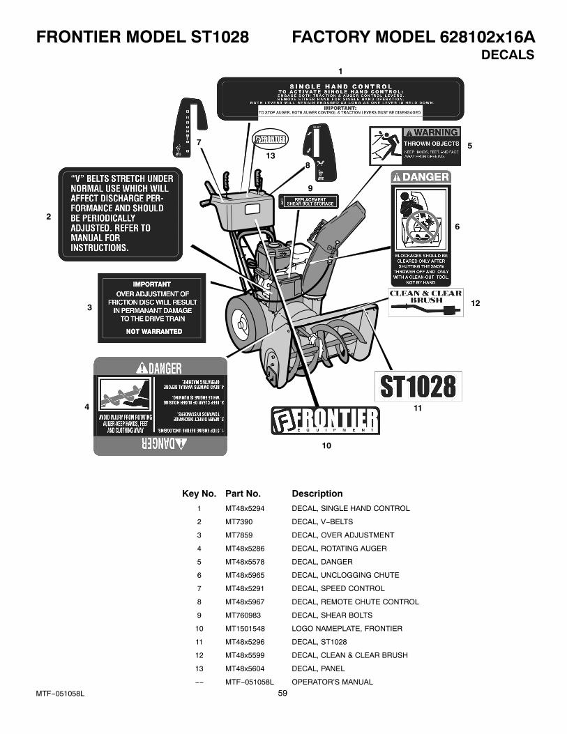
FRONTIER MODEL ST1028 FACTORY MODEL 628102x16A
59MTF−051058L
DECALS1
2
3
4
6
7
8
9
10
11
513
12
Key No. Part No. Description
1 MT48x5294 DECAL, SINGLE HAND CONTROL
2 MT7390 DECAL, V−BELTS
3 MT7859 DECAL, OVER ADJUSTMENT
4 MT48x5286 DECAL, ROTATING AUGER
5 MT48x5578 DECAL, DANGER
6 MT48x5965 DECAL, UNCLOGGING CHUTE
7 MT48x5291 DECAL, SPEED CONTROL
8 MT48x5967 DECAL, REMOTE CHUTE CONTROL
9 MT760983 DECAL, SHEAR BOLTS
10 MT1501548 LOGO NAMEPLATE, FRONTIER
11 MT48x5296 DECAL, ST1028
12 MT48x5599 DECAL, CLEAN & CLEAR BRUSH
13 MT48x5604 DECAL, PANEL
−− MTF−051058L OPERATOR’S MANUAL

SPECIFICATIONS ST1028
60MTF−051058L
Engine Briggs & Stratton Intek Snow OHV
Horsepower 10.5 hp
Starter Electric / Recoil
Fuel Capacity 4 quarts
Drive System Friction Disc
Speeds 6 Forward / 2 Reverse
Tire Diameter 16”
Traction Control Wheel Lock
Clearing Width 28”
Housing Height 21”
Auger Diameter 12”
Auger Type Steel / Saw Tooth
Impeller Diameter 12”
Chute Rotation Remote
Chute Turning Radius 190�
Deflector Control Remote
Weight 271 lbs
Warranty − Engine 3 years
Warranty − Machine 3 years


